retrofit of bridges in korea through viscous dampers ... · technology *samuele infanti 1, ... the...
TRANSCRIPT

13th World Conference on Earthquake Engineering Vancouver, B.C., Canada
August 1-6, 2004 Paper No. 2211
RETROFIT OF BRIDGES IN KOREA USING VISCOUS DAMPER TECHNOLOGY
*Samuele INFANTI1, H.T. KANG2, M.G. CASTELLANO3
SUMMARY
During the last two decades, seismic isolation and passive energy dissipation technology have undergone great development, finding many applications in both new and old conventional bridges as well as major structures like suspended and cable-stayed bridges.
This paper aims to illustrate the seismic protection system conceived to protect several bridges in Korea like the Seo-Hae Grand Bridge Approaches, Ok-Yeo Bridge, Chun-Su Bridge, E-Po Bridge, Kang-Dong and several others. The use of viscous dampers was the methodology selected to mitigate seismic action on said structures upon the advent of an earthquake. Said dampers were designed to be installed at the deck-pier interface in all expansion piers. This technology has proven very helpful, particularly in retrofit applications where it is difficult to change service load static configurations and whn there is a requirement for additional damping.
The Korean Highway Corporation established an important testing protocol to verify damper behavior when dynamically cycled at the two different extremes of temperature (-25°C, 40°C) expected at the bridge site. Test results supporting design assumptions are presented here.
Once again, viscous dampers have shown to be a reliable, efficient and economical form of technology to protect structures located in earthquake-prone areas.
INTRODUCTION
The Korean peninsula had been thought to be an earthquake-free-zone even though more than 20 events of small earthquakes were observed every year. Until 1992, none of highway bridges were designed to withstand an earthquake. Seismic disasters in the 1980s and 1990s greatly impressed upon the Korean people the tragic consequences of earthquakes. Consequently, the Korean Bridge Design Standard
1 Manager, R. & D. Dept., FIP Industriale, Selvazzano Dentro, Italy, [email protected] 2 Structures Research Group Chief Researcher, Highway & Transportation Technology Institute, Korea
Highway Co., Gyeonggi-do, Korea, [email protected] 3 Research Engineer, R.& D. Dept., FIP Industriale, Selvazzano Dentro, Italy, [email protected]
Specifications adopted seismic design regulations in 1992 and enforced seismic design in practice. The emergence of seismic design regulations gave rise to many challenging tasks. One of them is how engineers can provide the necessary seismic capability to bridges under constructions as well as existing bridges. The Seo-Hae Grand Bridge Approaches, Chun-Su Bridge et al. share a common problem. Since these bridges were under construction, seismic design based on the ductility of piers was not applicable and the use of anti-seismic devices was the only feasible way to provide the necessary capabilities to the bridges. Isolation bearings, steel and viscous dampers were reviewed. Considering factors like function, cost, and construction, viscous dampers were chosen as the optimum solution for the bridges concerned. The Seo-Hae Grand Bridge Approaches project was the very first application of viscous dampers in the seismic protection of bridges in Korea. Acceptance of the newly introduced devices necessitated a series of tests to examine the performance of viscous dampers. Test results showed to be both reliable and effective. The effective use of viscous dampers in a seismic retrofit is presented as an example.
NON-LINEAR VISCOUS DAMPERS
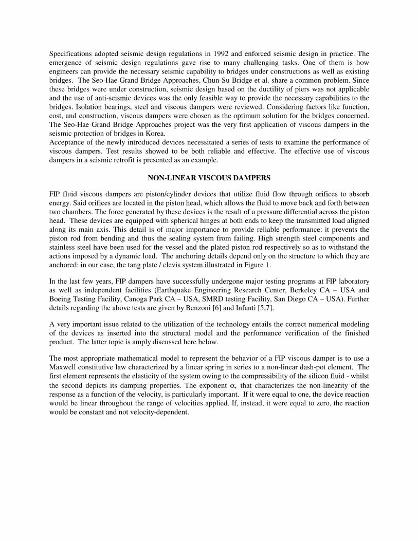
FIP fluid viscous dampers are piston/cylinder devices that utilize fluid flow through orifices to absorb energy. Said orifices are located in the piston head, which allows the fluid to move back and forth between two chambers. The force generated by these devices is the result of a pressure differential across the piston head. These devices are equipped with spherical hinges at both ends to keep the transmitted load aligned along its main axis. This detail is of major importance to provide reliable performance: it prevents the piston rod from bending and thus the sealing system from failing. High strength steel components and stainless steel have been used for the vessel and the plated piston rod respectively so as to withstand the actions imposed by a dynamic load. The anchoring details depend only on the structure to which they are anchored: in our case, the tang plate / clevis system illustrated in Figure 1.
In the last few years, FIP dampers have successfully undergone major testing programs at FIP laboratory as well as independent facilities (Earthquake Engineering Research Center, Berkeley CA – USA and Boeing Testing Facility, Canoga Park CA – USA, SMRD testing Facility, San Diego CA – USA). Further details regarding the above tests are given by Benzoni [6] and Infanti [5,7].
A very important issue related to the utilization of the technology entails the correct numerical modeling of the devices as inserted into the structural model and the performance verification of the finished product. The latter topic is amply discussed here below.
The most appropriate mathematical model to represent the behavior of a FIP viscous damper is to use a Maxwell constitutive law characterized by a linear spring in series to a non-linear dash-pot element. The first element represents the elasticity of the system owing to the compressibility of the silicon fluid - whilst the second depicts its damping properties. The exponent α, that characterizes the non-linearity of the response as a function of the velocity, is particularly important. If it were equal to one, the device reaction would be linear throughout the range of velocities applied. If, instead, it were equal to zero, the reaction would be constant and not velocity-dependent.

Figure 1 -Viscous Damper as installed inside the box girder of the Seo-Hae Bridge Approaches.
FIP viscous dampers provide for a 0.15 exponent. Thus, within a wide velocity range, reaction is almost constant. The latter behavior is remarkable because it permits the devices to already initiate a damping reaction at low velocities. Said effect, maximizes a reduction in bridge deck displacements. In other words, a device characterized by larger α exponent at an equal level of load transmitted to the structure would permit greater displacement. Generally speaking, positive effects are undoubtedly related to low exponent dampers: lesser pier deformation, lower expansion joint costs and cost effective bearings.
The graph of figure 2 illustrates a typical hysteresis loop for the devices under discussion when the input is a sinusoidal time-history. Note that device reaction reaches a maximum near the point of null displacement but nonetheless maintains itself almost constant until the motion reverses. Total system elasticity, mathematically represented by the stiffness K, depends on the compressibility of the fluid and it is particularly evident at the point of motion reversal, or at any rate, at the point of transitory phases: commonly, it is a secondary effect and often it is not even computed.
To evaluate the response of such a system, the differential non-linear equation representing its constitutive law needs to be integrated.
Looking at the plot in Fig.2, it can be noted that this typical hysteresis loop looks almost rectangular even when the displacement time–history is sinusoidal (and thus velocity-dependent). This is due to the damper's characteristic exponent (0.15). In fact, the behavior is almost independent from velocity. Thus total damper behavior can be similar to that of a spring in series to a ”perfectly plastic” element characterized by a constant threshold Force. This behavior can be easily modeled by a bi-linear element, where the first branch of its characteristic curve has the same stiffness K of the previous Maxwell Model and the second branch presents null stiffness. This last damper modeling procedure commonly leads to almost the same results as the Maxwell Model.

Test 1 - Performance Benchmark (TA #3)
-800
-600
-400
-200
0
200
400
600
800
-250 -200 -150 -100 -50 0 50 100 150 200 250 300
Displacement (mm)
Fo
rce
(kN
)
Maxwell Model
K C, α
x(t)
α
ω
⎟⎟⎠
⎞⎜⎜⎝
⎛−=
=
K
FxCF
tsinxx
&
&
)(0
Figure 2 -Damper Constitutive Law and Hysteresis Loop
APPLICATION OF VISCOUS DAMPERS TO BRIDGE RETROFITS
Seo-Hae Grand Bridge Approaches
Background of Retrofit The Seo-Hae Grand Bridge comprises 3 different types of bridges: a cable-stayed bridge (990m), an FCM bridge (500m), and PSM bridges (5820m) as shown in figure 3. These bridges, designed in the late 80’s, were revised during construction when the seismic design requirements appeared in 1992. Fortunately, the cable-stayed and FCM bridges satisfied the requirements of the specifications. However, there were some questions regarding the approaches, i.e. PSM bridges. One of the questions regards the magnitude of the earthquake force used in the original design. Even though there was no definition of the earthquake force in the Korean specifications at that time, the designers used 6% of self-weight as the earthquake force. Since this is much smaller than the earthquake force in the current specifications, the bridges do not satisfy the current seismic design code. Another question regarded the efficiency of shear keys. Shear keys were used to prevent the superstructure from falling down and to equally distribute the horizontal earthquake force to all piers. Such an idea was not very realistic because the gaps between the shear keys and the superstructure were different from pier to pier. Consequently, the earthquake force can be concentrated in a few piers and the force is great enough to break said piers. The Korean Highway Cooperative decided to reinforce the PSM bridges. Seismic Retrofitting of the Approaches, PSM Bridges The PSM bridges comprise 16 bridges: 3 to 10 continuous span bridges as shown in Fig. 3. There are two concrete box girders in the superstructure. Each box is 17m wide to accommodate 3 lanes of traffic. The substructure comprises a rigid-frame pier, a footing, and cast-in-place concrete piles. The height of the piers varies from 12 to 60 m. The rigid-frame pier has two hollow section columns as shown in Fig. 4. The dynamic characteristics are very different from one bridge to another: the height of the longest pier is 5 times taller than that of the shortest pier and the spans of the superstructures vary from 3 to 10. Therefore, the problems or concerns regarding the seismic design of these two bridges could be different. First of all, the capacity of the existing piers was assessed by experiments and numerical evaluation. The

results of this study showed that only 5 out of 16 PSM bridges needed to be retrofitted. These bridges are located near both the abutments where the piers are short. Many types of seismic devices were reviewed. Amongst them, the viscous damper was selected as the most suitable for PSM bridges. 54 viscous dampers were placed between the superstructure and the pier as shown in Fig. 5. They were installed at every pier except the piers at the expansion joints and those with fixed bearings.
Figure 3 - Elevation View of Seo-Hae Grand Bridge
Figure 4 - Typical PSM Bridges Piers

Figure 5 - Installation of Viscous Fluid Dampers
Testing Three prototypes of the three types of devices proposed underwent testing during the Autumn of the year 2000 at the FIP Industriale laboratory. A test rig, equipped with a 550kN (stroke ±150mm) actuator, instrumented with a displacement transducer and a load cell was set up. All the devices had a common constitutive law characterized by the following parameters:
K=100 kN/mm; C=219.75 kN/(mm/s)α; α=0.15.
Said devices, respectively denominated as OTP50/200, OTP50/300 and OTP50/400, only differed in the design stroke, equal to a ±100, ±150 and ±200mm respectively.
These dampers were designed to react with a 500kN force at the maximum design velocity of 240 mm/s.
The Client, concerned with verifying their behavior even at extreme design temperatures equal to -25°C and 40°C, expressively requested that some of the tests be conducted under such conditions.
To this effect, each prototype was tested creating an acclimatizing chamber around them in which a mixture of liquid and gaseous nitrogen was insufflated so as to condition the device to a temperature of -25°C. Conditioning to a temperature of 40°C was easily accomplished by means of a enveloping the damper vessel with a resistor system.
Performance Verification / Constant Velocity Test The aim of this test was to verify the prototypes’ constitutive law. To this effect, each device was subjected to cyclic tests at a constant velocity of, respectively, 25%, 50%, 75% and 100% of the design velocity. The acceptance criterion for the devices tested comprised the verification that damper reaction at the test velocity be within ±15% of the constitutive law reaction independent of the working temperature. To achieve this, the above mentioned tests were repeated both at –25°C and 40°C respectively. The values obtained were those presented in the graph illustrated in Fig.6.
It should be noted that device reaction is almost independent from the testing temperature, furnishing variations between the extreme temperatures in the order of 3%, thus confirming once more a very stable damper behavior. This effect was also verified by the Energy Dissipation Test.
All the devices demonstrated full functionality according to contract specifications.

0 20 40 60 80 100 120 140 160 180 200 220 240 260Velocity [mm/s]
0
100
200
300
400
500
600
Loa
d [k
N]
T= 40 °C
T= -25 °C
Design Constitutive Law
Lower Bound Limit (-15%)
Upper bound Limit (+15%)
OTP 50/300
Performance Verification / Constant Velocity Test
F= 219.75*V0.15
Figure 6 - Performance verification test: plotted results.
Energy Dissipation Test This test aimed to verify the ability of the dampers to dissipate energy (damper energy dissipation capacity) under a cyclic input. The acceptance criterion stipulated by the specifications was that the energy dissipated be not lesser than 90% of the design capacity. The test was conducted applying an imposed displacement under a sinusoidal law: this choice was exercised so as to verify device behavior in the face of variable displacement input as a function of time. From a testing standpoint, the only difficulty met was having a sufficiently powerful system to carry out the test (mean effective power required: 120 kW).
To evaluate the results, it was necessary to undertake the following procedure.
To compute the theoretically dissipated energy (the area of the hysteresis loop) it was necessary to numerically solve the non-linear differential equation shown in Fig.2 for an imposed sinusoidal displacement and then proceed to integrate the same. Of course, the boundary conditions must be the same as those of the tested device so the amplitude of the sinusoidal input is equal to the average between the maximum experimental displacements in the two directions of motion. The sinusoid period must be such as to provide a maximum velocity equal to the average between the maximum experimental velocities in the two directions of motion.
All the devices in question demonstrated full functionality according to contract specifications.
Fig.7 shows typical experimental hysteresis loops obtained during this test campaign. It is worth mentioning that the dampers showed very good testing replicability providing almost no variation in force. In the graph, the corresponding theoretical hysteresis loop has been overlaid on the experimental ones. It is clear that the theoretical Maxwell model describes the studied phenomenon well.

Cycle n° 2 Cycle n° 6 Cycle n° 9
F1 [kN] 459.7 461.4 459
V1 [mm/s] 237 236 236
X1 [mm] 88.3 88.3 88.4
F2 [kN] 460 463 459
V2 [mm/s] 245 246 247
X2 [mm] 88.2 88.4 88.3
E.D.C. [kJ] 149.6 151.7 150.8
-125 -100 -75 -50 -25 0 25 50 75 100 125
Stroke [mm]
-600
-500
-400
-300
-200
-100
0
100
200
300
400
500
600L
oad
[kN
] F1 & V1
Sinusoidal Energy Dissipation Test on OTP 50/300 ( T = 40 °C)
X1
F2 & V2
X2
Theoretical Loop --------
--->
n° 9n° 6
n° 2
Cycles<-----
--- Experimental Loops
Figure 7 - Theoretical and Experimental Hysteresis Loops
Endurance Test The aim of this test was to verify the behavior of the sealing system when subjected to multiple displacement cycles at very low velocities. In other words, to simulate the effect of bridge expansion/contraction upon the device induced by thermal deformation as well as to verify that any possible wear and tear on the seals would not be such as to cause any fluid leakage.
With this in mind, each of the prototypes was subjected to cyclic stressing at low velocity, equivalent in terms of total stroke to 1800 displacement cycles at the maximum design stroke. Each test on a single damper lasted about eight days. No damage to the seals or leakage of fluid was ascertained during or after the tests. The tests were conducted at ambient temperature and all the devices demonstrated full functionality according to contract specifications.
Friction Test The objective of this test was to evaluate the resistance opposed by the device to movements applied very slowly such as those induced by bridge thermal expansion/contractions.
The contractual acceptance criterion proposed was that of limiting damper resistance to 10% of the design reaction of the device throughout the entire temperature range. The test velocity used to represent such an effect was 0.01 mm/s. It should be noted that such a value is much higher than the bridge deck effective velocity of deformation and thus, that the results obtained at such a velocity are higher than actual values. This test was also repeated at the two design temperature extremes. All the devices demonstrated full functionality according to contract specifications. It should be noted that there is greater temperature dependence in the reaction at very low velocities. At –25°C, the drag force is greater than about twice that found at 40°C, but nonetheless within the limits stipulated by the specification.
Following projects After the first successful application of the damper technology, other projects using the same design philosophy applied to the Seo-Hae bridge immediately followed: Ok-Yeo Bridge, Chun-Su Bridge, E-PO

bridge, Kang-Dong bridge, Dong-Yun Bridge, Nam-Chang Second Bridge, Chu-Ryung Bridge, Chun-Chun Bridge, Su-Jik Bridge, Back-Won Bridge and Han-Jik Bridge.
Most of these bridges had been originally designed for a 0.06g PGA.
Since the first application of viscous dampers in Korea (year 2000), more than 11 km of viaducts have been successfully protected with 252 FIP Viscous dampers.
The following paragraphs report information regarding some of the aforesaid bridges.
Ok-Yeo Bridge
The Ok-Yeo Bridge is located in the central part of Korea and has a total length of 430 m.
The structure comprises two independent continuous concrete decks of the concrete box girder type. The piers are characterized by rectangular hollow sections 4 x 6 m or 4 x 9.4 m and their height ranges from 13 to 46 m.
The piers are founded on 9x12x2.5m concrete basements.
Almost at the time of the traffic opening, the PGA was increased by the Korean code to 0.14g, so it was proposed to improve the seismic behavior of the structure by adding viscous dampers.
Figure 8 - Viaduct configuration (elevation).
Figure 9 - The Ok-Yeo Bridge.
The original bearing layout comprised pot bearings of the fixed type, at the central and tallest piers locations and guided or free sliding pot bearings at the other locations. In order to protect the substructure from a seismic event having an acceleration equal to 0.14g, the designer suggested adding a damping system along the longitudinal axis of the bridge. The layout bearing being similar to the one of the Seo-Hae Bridge, the solution seemed to perfectly fit the new safety requirement.
Figure 8 shows the general bridge configuration as well as its damper lay-out.
The seismic protection system used for this bridge comprises a combination of non-linear fluid viscous dampers and pot bearings. The bearings were designed and installed according to the previous design.

Figure 10 - The Ok-Yeo Bridge Dampers.
Figure 11 - A Damper as installed.
Pier 4 and 5, the tallest along the viaduct, are provided with fixed pot bearings so that in the absence of any seismic protection device, all the seismic loads are concentrated at these locations and their capacity exceeded by the seismic demand.
The addition of viscous dampers at all the expansion piers provided two effects: first of all, the piers were called to withstand a longitudinal seismic force (force distribution) and second, their action dissipates the earthquake-induced energy introduced by the ground motion. As a result, the longitudinal computed action resulted lower than the available capacity, thus providing a demand/capacity ratio lower than one.
In the transverse direction, the bridge was deemed to have sufficient capacity to withstand the new level of design acceleration due to the good distribution of the seismic load as well as intrinsic pier strength.
In order to estimate the actions on the structure, a step-by- step non linear analysis was performed using three artificially generated accelerograms compatible with design spectra (AASHTO, Soil Type II). The maximum results were used for design purposes. A parametric analysis was performed to evaluate damper characteristics. Their force capacity was estimated to be 500 kN each, considering the installation of one unit at each expansion pier, so that a total of 12 units were provided for this project. The maximum seismic design displacement was evaluated as ±68mm. Thus, in view of the fact that dampers should be designed to also allow for thermal deck expansions, devices providing a ±200mm stroke were considered. Figure 10 shows a drawing depicting the dampers as installed at each expansion pier.
CHUN-SU Bridge
The Chun-Su Bridge is located along the Seo-Hae Highway, south to Seoul, and has a total length of 766 m. The bridge was completed in the year 2001.

Figure 12 - The Chun-Su Bridge.
Figure 13 - A Damper as installed.
The structure comprises two continuous concrete decks (33m+14@50m+33m) of the pre-stressed concrete box type. The piers are characterized by height ranging from 7 to 12 m.
The original bearing layout comprised pot bearings of the fixed type, at the central and tallest piers. In order to protect the substructure from a seismic event having a peak ground acceleration of 0.154g, the designer again suggested adding a damping system along the longitudinal axis of the bridge.
Figures 12 and 13 shows a photo of the bridge is an a damper installed.
The seismic protection system used for this bridge comprises a combination of non-linear fluid viscous dampers and pot bearings. The bearings were designed and installed according to the previous design.
Pier 8, located in the middle of the bridge, is equipped with fixed pot bearings so that in the absence of any seismic protection device, all the seismic loads are concentrated at these locations and their capacity exceeded by the seismic demand.
The addition of viscous dampers at some of the expansion piers provided two effects: first of all, the piers are called to withstand the longitudinal seismic force (force distribution) and second, their action dissipates the earthquake-induced energy introduced by the ground motion. As a result, the longitudinal computed action results lower than the available capacity and thus provides for a demand/capacity ratio lower than one.
In order to estimate the actions on the structure, a step-by- step non linear analysis was performed using ten artificially generated accelerograms compatible with the design spectra (AASHTO, Soil Type II, PGA 0.154g). Average of results was used for design purposes. The maximum seismic design displacement was evaluated as ±40mm. Thus, considering the fact that dampers should be designed to also allow for thermal deck expansions, devices providing for a ±120mm stroke were considered. Their force capacity was estimated as 850 kN each and one unit was installed at the expansion Piers P5-P7 and P9-P11, so that a total of 12 units was provided for the above project.
E-PO Bridge
The E-Po Bridge is located in the province of Kyung-Gy in the north-east part of S. Korea. The bridge was opened to traffic in 1992.

Figure 14 - E-Po Bridge configuration (elevation).
Figure 15 - The E-Po Bridge.
This structure comprises several concrete deck segments with a total length equaling 797m (48.5m+14@50m+48.5m). Each of the segments comprise two simply supported decks joined at the central pier by a continuity concrete slab so that one of every two piers is of the expansion type.
The piers are characterized by circular sections (3m dia.) and their height ranged from 13 to 19 m.
Figure 16 - The E-Po Bridge Damper as installed at the abutment.
Figure 17 - Longitudinal and Transverse Dampers as installed.
The original bearing lay-out comprised elastomeric bearings designed to only withstand service loads. In order to protect the substructure from a seismic event having a peak ground acceleration equal to 0.154g and to reduce the seismic displacement at the bearing interface, the designer considered adding a damping system along the longitudinal and transverse bridge axes respectively.
Figure 14 shows the general bridge configuration.

The seismic protection system used for this bridge comprises a combination of non-linear, fluid viscous dampers and the original elastomeric bearings.
Each segment is equipped with dampers installed longitudinally at each pier and transversally at the expansion piers (see figure 17).
Also in this case, the addition of viscous dampers provides for two main effects: force distribution and dissipation of the energy introduced by the ground motion. As a result, the longitudinal computed action results lower than the available capacity and thus provides a demand/capacity ratio lower than one.
In order to estimate the actions on the structure, a step-by- step non-linear analysis was performed using ten artificially generated accelerograms compatible with the design spectra (AASHTO, Soil Type II, PGA 0.154g). Average results were used for design purposes. The maximum seismic design displacement was evaluated as ±71mm. Thus, considering the fact that dampers should be designed to also allow for deck thermal expansions, devices providing for a ±100mm stroke were considered. Their force capacity was estimated as 500 kN per unit, so that a total of 32 units (24 longitudinal and 8 transverse dampers) were provided for this project.
Kang-Dong and Dong-Yun Bridges
The Kang-Dong Bridge is located in the province of Kyung-Gy in the north-east part of S. Korea. A two lanes bridge was opened to traffic in 1996. Then a second two lane deck, parallel to the first one, was added and opened to traffic in 2000.
Figure 18 - The Kang-Dong Bridge.
Figure 19 - Damper as installed on the Kang-Dong Bridge.
The structure comprises two continuous composite decks having a total length of 210m/each (45m+2@60m+45m). The seismic protection system is similar to the ones in the above mentioned projects and each deck is protected by 5 units characterized by a load capacity of 500kN (±100mm stroke).
Figures 18 and 19, show a general configuration of the bridge and a damper installed.
The Dong-Yun Bridge is located in the province of Kyung-Gy in the north-east part of S. Korea. The bridge was opened to traffic in 1996.

Figure 20 - The Dong-Yun Bridge.
Figure 21 - Transverse Damper as installed on the Dong-Yun Bridge.
The structure comprises two continuous concrete decks having a total length of 320m (4@40m+4@40m). The seismic protection system is similar to the E-Po Bridge project and each pier is connected to the deck by 2 units in order to provide both longitudinal and transverse protection. Each damper is characterized by a load capacity of 500kN (±100mm stroke).
Figures 20 and 21, show a photo of the bridge and a transversally oriented damper installed.
CONCLUSIONS
During the last few years, twelve bridges have been retrofitted in South Korea in order to increase their seismic resistance to moderate intensity earthquakes.
The first pilot project, whose design philosophy influenced the retrofit technique of the following ones, was the retrofit of the Seo-Hae Bridge approaches.
Viscous dampers were chosen because of their reliability and ease of installation. Furthermore, the proposed system was cost effective because it did not require the substitution of existing bearings.
An extensive test program of the seismic devices was developed and carried out for each project in order to verify the correspondence of design assumptions to the behavior of the units.
FIP Viscous dampers demonstrated a capability to produce very stable seismic reaction throughout the entire –25°C ÷ +40°C temperature range with negligible percent variation (about 3%). Such results guarantee the reliability of maximum damping capacity under any climactic condition.
More than 11 km of bridges in South Korea are already protected by means of fluid viscous dampers and the design of many more is presently in process.

ACKNOWLEDGEMENTS
The authors wish to express their sincere gratitude for the active and fruitful cooperation rendered by Dr. C.M. Park of the Korean Highway Corporation as well as the indefatigable support furnished by Mr. Pierluigi Galeazzo Testing Laboratory Manager of FIP Industriale and his staff.
REFERENCES
1. Castellano M.G., Colato G.P., Infanti S. “Use of viscous dampers or shock transmission units for seismic protection of buildings.” Proceedings of the 13th World Conference on Earthquake Engineering, Vancouver BC, Canada. Paper no. 2172. 2004.
2. Infanti S. “Seismic Protection of Seohae Bridge Approaches trough Viscous Dampers”. Proceedings of IABSE Conference Cable-Supported Bridges–Challenging Technical Limits, Seoul, Korea, 2001.
3. Infanti S., Castellano M.G. “ Viscous Dampers: a Testing Investigation according to the HITEC Protocol.” Proceeedings of Fifth World Congress on Joints, Bearings and Seismic Systems for Concrete Structures, Rome, Italy, 2001.
4. Technical Report “Guidelines for Testing of Seismic Isolation and Energy Dissipating Devices.” Highway Innovative Technology Evaluation Center, 1998.
5. Technical Report “Evaluation Findings of FIP Industriale Viscous Dampers according to the HITEC testing protocol.” Rocketdyne Division of Boeing, Canoga Park, CA, USA, 2000.
6. Benzoni G., Seible F. “Rion-Antirion Bridge - Prototype Tests of Damper FIP OTP 350/1800.” Caltrans SRMD Test Facility Report N. 2002/01, San Diego, CA, USA, 2002.
7. Infanti S., Papanikolas P., Theodossopoulos G. “Rion-Antirion Bridge: Full-Scale Testing of Seismic Devices”, Proceedings of fib Symposium Concrete Structures in Seismic Regions, Athens, Greece, 2003.
8. Infanti S., Papanikolas P., Castellano M.G. “Seismic protection of the Rion-Antirion Bridge.” Proceedings of 8th World Seminar on Seismic Isolation, Energy Dissipation and Active Vibration Control of Structures, Yerevan, Armenia, 2003.