results of testing of multi-beam klystrons for the
TRANSCRIPT

RESULTS OF TESTING OF MULTI-BEAM KLYSTRONS FOR THE EUROPEAN XFEL
V. Vogel, L. Butkowski, A. Cherepenko, S. Choroba, I Harders and J. Hartung, DESY, 22607 Hamburg, Germany
Abstract For the European XFEL multi-beam klystrons, which can produce RF power of 10 MW at an RF frequency of 1.3 GHz, at 1.5ms pulse length and 10 Hz repetition rate, were chosen as RF power sources. Twenty-seven of horizontal multi-beam klystrons (MBK) together with connection modules (CM) will be installed in the XFEL underground tunnel. The CM will be installed on the MBK and connects the MBK to the pulse transformer with only one HV cable, because the CM has a filament transformer inside as well as all diagnostics for HV and cathode current measurements. MBK prototypes together with CM prototypes have been tested for long time at a test stand at DESY, about 4600 hours of operation for each of horizontal MBK with full RF output power, full pulse length and repetition rate of 10 Hz. Testing of first MBKs from series production has been started. In this paper we will give an overview of the test procedure, summarize the current test results and we will give a comparison of the most important parameters.
INTRODUCTION For the XFEL project [1] as a source of RF power for 27 RF station were chosen the horizontal MBK made by two companies: MBK TH1802 from “Thales” [3] and MBK E3736H from “Toshiba” [4]. The main parameters of MBK are given in Table 1.
Table 1: Main parameters of L-band MBK for XFEL
Parameters Design value Test value
Output power (MW) 10 10.3
RF pulse length (ms) 1.5 1.5
Efficiency (%) > 63 64
Repetition rate (Hz) up to 30 10
Max average RF power ( 150 155
Max average power in collector (kW)
300 270
Max drive power (W) <200 <150
Bandwidth (MHz) 3 >3
Both prototypes of MBK were tested on DESY MBK test stands [2], a total time of testing exceed of 4600 hours for both of tubes. The test was done with full RF power of 10 MW, full RF pulse length of 1.5 ms and with repetition rate of 10 Hz. Fig. 1 shows the top view of the test stands. Because the all of RF station will be located in the
underground tunnel it is very important do not have the open oil during installation of MBK. It was proposed and tested the connection between MBK and HV pulse transformer through connection module (CM) [5, 6 and 7] and HV cable. Several types of HV cables and connectors as well as CM prototypes were tested. Big advances of using CM are that CM has inside a high voltage high frequency filament transformer and monitors for measurement of klystron voltage and cathode current. Fig. 2 shows the one of klystrons with CM and HV cable.
Figure 1: MBK test stands in DESY Hamburg
Figure 2: MBK with CM and HV cable “PFISTERER 3S”
RESULTS OF MBK PROTOTYPES TEST Since February 2008 we started the test of the first of horizontal MBK prototype on DESY site. For the test of MBK it was specially developed two radiation protected
kW)
TUPLB04 Proceedings of LINAC2012, Tel-Aviv, Israel
ISBN 978-3-95450-122-9
448Cop
yrig
htc ○
2012
byth
ere
spec
tive
auth
ors—
ccC
reat
ive
Com
mon
sAtt
ribu
tion
3.0
(CC
BY
3.0)
01 Electron Accelerators and Applications
1D FELs
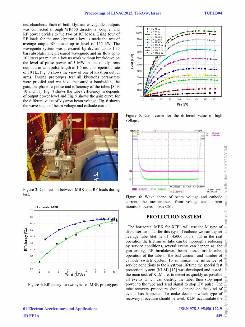
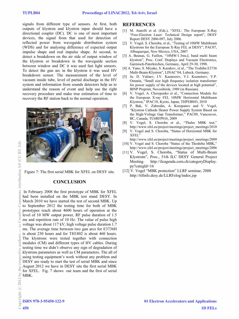
test chambers. Each of both klystron waveguides outputs was connected through WR650 directional coupler and RF power divider to the two of RF loads. Using four of RF loads for the one klystron allow us made the test of average output RF power up to level of 155 kW. The waveguide system was pressured by dry air up to 1.35 bars absolute. The pressured waveguide and air flow up to 10 litters per minute allow us work without breakdown on the level of pulse power of 5 MW in one of klystrons output arm with pulse length of 1.5 ms and repetition rate of 10 Hz. Fig. 3 shows the view of one of klystron output arms. During prototypes test all klystrons parameters were proofed and we have measured a bandwidth, the gain, the phase response and efficiency of the tubes [8, 9, 10 and 11]. Fig. 4 shows the tubes efficiency in depends of output power level and Fig. 5 shows the gain curve for the different value of klystron beam voltage. Fig. 6 shows the wave shape of beam voltage and cathode current.
Figure 3: Connection between MBK and RF loads during test.
Figure 4: Efficiency for two types of MBK prototypes.
Pin (W)0 25 50 75 100 125 150 175 200
Pou
t (kW
)
0
1000
2000
3000
4000
5000
6000
7000
8000
9000
10000
11000U = 67 kV U = 74 kV U = 84 kV U = 87.6 kV U = 92.4 kV U = 99.4 kV U = 104.8 kV U = 110.4 kV U = 114.6 kV U = 116.5 kV
Figure 5: Gain curve for the different value of high voltage.
Figure 6: Wave shape of beam voltage and cathode current, the measurement from voltage and current monitors located inside CM.
PROTECTION SYSTEM
The horizontal MBK for XFEL will use the M type of dispenser cathode, for this type of cathode we can expect average tube lifetime of 145000 hours, but in the real operation the lifetime of tube can be thoroughly reducing by service conditions, several events can happen as: the gun arcing, RF breakdown, beam losses inside tube, operation of the tube in the bad vacuum and number of cathode switch cycles. To minimize the influence of service conditions to the klystrons lifetime the special fast protection system (KLM) [12] was developed and tested, the main task of KLM are: to detect as quickly as possible all events which can destroy the tube, then stop input power to the tube and send signal to stop HV pulse. The tube recovery procedure should depend on the kind of events has happened. To make decision which type of recovery procedure should be used, KLM accumulate the
Horizontal MBK
Pout (MW)2 3 4 5 6 7 8 9 10
Effi
cien
cy (%
)
25
30
35
40
45
50
55
60
65
70
Proceedings of LINAC2012, Tel-Aviv, Israel TUPLB04
01 Electron Accelerators and Applications
1D FELs
ISBN 978-3-95450-122-9
449 Cop
yrig
htc ○
2012
byth
ere
spec
tive
auth
ors—
ccC
reat
ive
Com
mon
sAtt
ribu
tion
3.0
(CC
BY
3.0)
signals from different type of sensors. At first, both outputs of klystron and klystron input should have a directional coupler (DC). DC is one of most important devices, the signal from that used for detection of reflected power from waveguide distribution system (WDS) and for analysing difference of expected output impulse shape and real impulse shape. At second, to detect a breakdown on the air side of output window of the klystron or breakdown in the waveguide section between window and DC it was used fast light sensors. To detect the gun arc in the klystron it was used HV breakdown sensor. The measurement of the level of vacuum inside tube, level of partial discharge in the HV system and information from sounds detectors help us to understand the reason of event and help use the right recovery procedure and make true estimation of time to recovery the RF station back to the normal operation.
Figure 7: The first serial MBK for XFEL on DESY site.
CONCLUSION
In February 2008 the first prototype of MBK for XFEL had been installed on the MBK test stand DESY. In March 2010 we have started the test of second MBK. Up to September 2012 the testing time for both of MBK prototypes reach about 4600 hours of operation at the level of 10 MW output power, RF pulse duration of 1.5 ms and repetition rate of 10 Hz. The value of pulse high voltage was about 117 kV, high voltage pulse duration 1.7 ms. The average time between two gun arcs for E3736H is about 230 hours and for TH1802 is about 460 hours. The klystrons were tested together with connection modules (CM) and different types of HV cables. During testing time we didn’t observe any sign of degradation of klystrons parameters as well as CM parameters. The all of using testing equipment’s work without any problem and DESY are ready to start the test of serial MBK and since August 2012 we have in DESY site the first serial MBK for XFEL. Fig. 7 shows our team and the first of serial MBK.
REFERENCES [1] M. Atarelli et al. (Eds.), “XFEL: The European X-Ray
“Free-Electron Laser: Technical Design report”, DESY Report DESY 2006-097, July 2006.
[2] V. Vogel, S. Choroba, et al., “Testing of 10MW Multibeam Klystrons for the European X-Ray FEL at DESY”, PAC07, Albuquerque, New Mexico, USA, 2007
[3] A. Beunas, G. Faillon, “10MW/1.5ms,L band multi beam klystron”, Proc. Conf. Displays and Vacuum Electronics, Garmisch-Paterkirchen, Germany, April 29-30, 1998.
[4] A. Yano, S. Miyake, S. Kazakov, et al., “The Toshiba E3736 Multi-Beam-Klystron”, LINAC’04, Lubeck, Germany.
[5] Ju. D. Valiaev, I.V. Kazarezov, V.I. Kuznetsov, V.P. Ostanin, “Small size high frequency isolation transformer for power supply of the devices located at high potential”, BINP Preprint, Novosibirsk, 1989 (in Russian).
[6] V. Vogel, A. Cherepenko et al., “Connection Module for the European X-ray FEL 10MW Horizontal Multibeam Klystron,” IPAC10, Kyoto, Japan, THPEB043, 2010
[7] P. Bak, V. Zabrodin, A. Korepanov and V. Vogel, “Klystron Cathode Heater Power Supply System Based on the High-Voltage Gap Transformer,” PAC09, Vancouver, BC, Canada, TU6RFP016, 2009
[8] V. Vogel, S. Choroba et al., “Thales MBK test,” http://www.xfel.eu/project/meetings/project_meetings/2010
[9] V. Vogel and S. Choroba, “Status of Horizontal MBK for XFEL” http://www.xfel.eu/project/meetings/project_meetings/2009
[10] V. Vogel and S. Choroba “Status of the Thoshiba MBK,” http://www.xfel.eu/project/meetings/project_meetings/2006
[11] V. Vogel, S. Choroba, “Status of Multi-Beam Klystrons”, Proc., 51th ILC DESY General Project Meeting. http://ilcagenda.cern.ch/categoryDisplay. py?categId=16
[12] V. Vogel “MBK protection” LLRF seminar, 2008 http://ttfinfo.desy.de/LLRFelog/index.jsp
TUPLB04 Proceedings of LINAC2012, Tel-Aviv, Israel
ISBN 978-3-95450-122-9
450Cop
yrig
htc ○
2012
byth
ere
spec
tive
auth
ors—
ccC
reat
ive
Com
mon
sAtt
ribu
tion
3.0
(CC
BY
3.0)
01 Electron Accelerators and Applications
1D FELs