response of square tension leg platforms to hydrodynamic
TRANSCRIPT
Ocean Systems Engineering, Vol. 2, No. 2 (2012) 115-135 115
Response of square tension leg platforms to hydrodynamic forces
A.M. Abou-Rayan1, Ayman A. Seleemah*2 and Amr R. El-gamal1
1Civil Engineering Tec. Dept., Faculty of Engineering, Benha Univ., Egypt2Structural Engineering Dept., Faculty of Engineering, Tanta Univ., Egypt
(Received September 5, 2011, Revised June 1, 2012, Accepted June 7, 2012)
Abstract. The very low natural frequencies of tension leg platforms (TLP’s) have raised the concernabout the significance of the action of hydrodynamic wave forces on the response of such platforms. Inthis paper, a numerical study using modified Morison equation was carried out in the time domain toinvestigate the influence of nonlinearities due to hydrodynamic forces and the coupling effect betweensurge, sway, heave, roll, pitch and yaw degrees of freedom on the dynamic behavior of TLP's. Thestiffness of the TLP was derived from a combination of hydrostatic restoring forces and restoring forcesdue to cables and the nonlinear equations of motion were solved utilizing Newmark’s beta integrationscheme. The effect of wave characteristics such as wave period and wave height on the response of TLP'swas evaluated. Only uni-directional waves in the surge direction was considered in the analysis. It wasfound that coupling between various degrees of freedom has insignificant effect on the displacementresponses. Moreover, for short wave periods (i.e., less than 10 sec.), the surge response consisted of smallamplitude oscillations about a displaced position that is significantly dependent on the wave height;whereas for longer wave periods, the surge response showed high amplitude oscillations about its originalposition. Also, for short wave periods, a higher mode contribution to the pitch response accompanied byperiod doubling appeared to take place. For long wave periods, (12.5 and 15 sec.), this higher modecontribution vanished after very few cycles.
Keywords: compliant structures; tension leg platforms; hydrodynamic wave forces; coupling effect;wave period; wave height
1. Introduction
Since the late 1940’s, when offshore drilling platforms were first used in the gulf of Mexico there
has been a large increase in the number of offshore platforms put into service. Production activities
at their sites are generally carried out using fixed offshore platforms, which are valid only for
shallow waters. For deep waters, however, it is uneconomic to build a stiff jacket or gravity type
platform to resist the wave loads. Therefore, the compliant platforms, an engineering idea to
minimize the structure resistance to environmental loads by making the structure flexible, have been
introduced. A tension leg platform (TLP) is one of the compliant structures which are well
established in offshore industry. The TLP is basically a floating structure moored by vertical cables
or “tethers”. Tethers are pre-tensioned to the sea floor due to the excess buoyancy of the platform.
*Corresponding author, Professor, E-mail: [email protected]
DOI: http://dx.doi.org/10.12989/ose.2012.2.2.115

116 A.M. Abou-Rayan, Ayman A. Seleemah and Amr R. El-gamal
This tension fluctuates due to variable submergence, wind gustiness, wave loading and resulting
coupled response. The instantaneous tension in tethers acts as a restoring force.
The TLP can be modeled as a rigid body with six degrees of freedom (refer to Fig. 1), which can be
conveniently divided into two categories, those controlled by the stiffness of tethers, and those
controlled by the buoyancy. The former category includes motion in the vertical plane and consists of
heave, roll and pitch; whereas the latter comprises the horizontal motions of surge, sway and yaw .The
natural periods of motion in the horizontal plane are high, whereas in the vertical plane the periods
are low. Generally, the surge and sway motions are predominantly high for head seas due to the
combined actions of wind, waves and currents. However, due to coupling among various degrees of
freedom and relatively low damping of hydrodynamic origin in the vertical plane motion, a
complete analysis of a six degree-of-freedom system subjected to wind, waves and currents is
desirable. Moreover, the structural flexibility in the horizontal motions causes nonlinearity in the
structural stiffness matrix because of large deformations.
The natural periods of the horizontal plane motions are higher than typical wave period which
precludes resonance with the wave diffraction forces. However, the wave-induced low frequency
forces, namely the wave drift forces, could be close (to some extent) to the natural periods of
motion in the horizontal plane causing a significant response of a TLP despite the low amplitude of
these forces. The maximum TLP response at low frequencies in various extreme environmental
conditions is of primary importance from the point of view of platform stability, serviceability and
fatigue of tethers.
A number of studies have been conducted on the dynamic behavior of TLP’s under both regular
and random waves, (Taudin 1978, Denis and Heaf 1979, Tan and De Boom 1983). The majority of
these studies deal with the two dimensional behavior of the platform. Few investigations, however
considered all the six degrees of freedom of the platform in describing its dynamic behavior,
Morgan and Malaeb (1983) Chandrasekaran and Roy (2005). They presented phase space studies of
offshore structures subjected to nonlinear dynamic loading through Poincare maps for certain
hydrodynamic parameters. Bhattachatya et al. (2004) investigated coupled dynamic behavior of a
mini TLP giving special attention to hull-tether coupling. Ketabdari and Ardakani (2005) developed
a computer program to evaluate the dynamic response of sea-star TLP to regular wave forces
considering coupling between different degrees of freedom. Wave forces were computed
numerically using linear wave theory and Morison equation, neglecting diffraction effects due to
Fig. 1 The global and local coordinate system of TLP
Response of square tension leg platforms to hydrodynamic forces 117
small ratio of diameter to wave length. Lee and Wang (2000) investigated the dynamic behavior of
a TLP with a net-cage system with a simplified two-dimensional modeling. They found that there is
a close relationship between the dynamic behavior of the platform and the net-cage features. Low
(2009) presented a formulation for the linearization of the tendon restoring forces of a TLP.
Chandrasekaran et al. (2007a) conducted dynamic analysis of triangular TLP models at different
water depths under the combined action of regular waves and an impulse load affecting the TLP
column. Chandrasekaran et al. (2007b) focused on the response analysis of triangular tension leg
platform (TLP) for different wave approach angles and studied its influence on the coupled dynamic
response of triangular TLPs. Kurian et al. (2008a) developed a numerical study on the dynamic
response of square TLPs subjected to regular and random waves. They also conducted parametric
studies with varying parameters such as water depth, pretension, wave angle and position of center
of gravity. Kurian et al. (2008b) developed a numerical study on determining the dynamic responses
of square and triangular TLPs subjected to random waves. They found that the responses of
triangular TLPs are much higher than those of square TLP. Recently, Yang and Kim (2010)
developed a numerical study of the transient effect of tendon disconnection on the global
performance of an extended tension leg platform (ETLP) during harsh environmental conditions of
the gulf of Mexico.
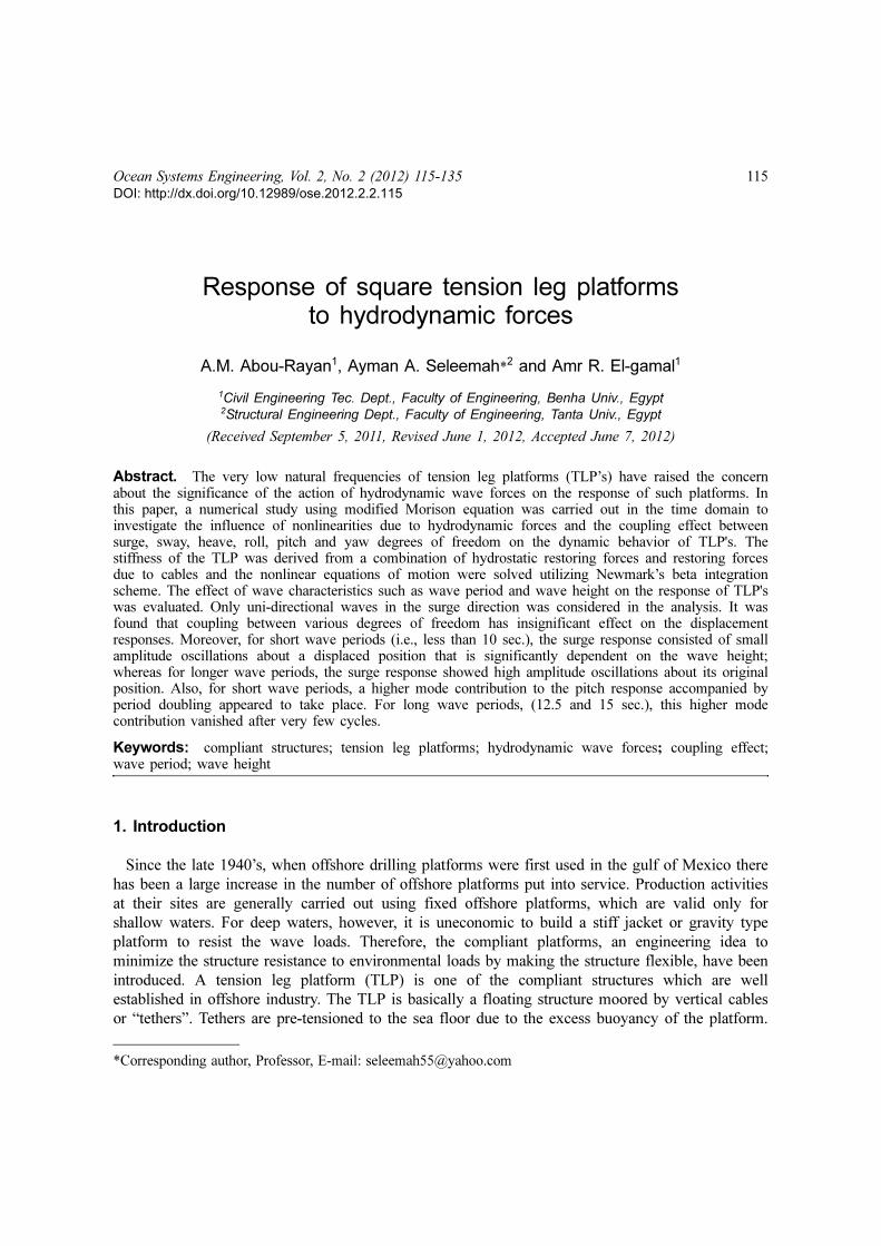
In this paper, a numerical study was conducted to investigate the dynamic response of a
rectangular TLP (shown in Fig. 2) under hydrodynamic forces considering all degrees of freedom of
the system. The analysis was carried out using modified Morison equation in the time domain with
Fig. 2 The Square TLP (plan and elevation)

118 A.M. Abou-Rayan, Ayman A. Seleemah and Amr R. El-gamal
water particle kinematics using Airy’s linear wave theory. The influence of nonlinearities due to
hydrodynamic forces and the coupling effect between surge, sway, heave, roll, pitch and yaw
degrees of freedom on the dynamic behavior of TLP's was investigated. The stiffness of the TLP
was derived from a combination of hydrostatic restoring forces and restoring forces due to cables
and the nonlinear equations of motion were solved utilizing Newmark’s beta integration scheme.
The effect of wave characteristics such as wave period and wave height on the response of TLP's
was evaluated. Only uni-directional waves in the surge direction was considered in the analysis.
2. Structural idealization and assumptions
The general equation of motion of the rectangular configuration TLP model under a regular wave
is given as
(1)
Where, {x} is the structural displacement vector, is the structural velocity vector, {x¨} is the
structural acceleration vector; [M] is the structure mass matrix; [C] is the structure damping matrix;
[K] is the structure stiffness matrix; and {F(t)} is the hydrodynamic force vector.
The mathematical model derived in this study assumes that the platform and the tethers are treated
as a single system and the analysis is carried out for the six degrees of freedom under different
environmental loads where wave forces are estimated at the instantaneous equilibrium position of
the platform utilizing Morison’s equation and using Airy’s linear wave theory. Wave force
coefficients, Cd and Cm, are the same for the pontoons and the columns and are independent of
frequencies as well as constant over the water depth. The following assumptions were made in the
analysis.
1. Change in pre-tension is calculated at each time step, so the equation of equilibrium at each
time step modifies the elements of the stiffness matrix.
2. The platform has been considered symmetrical along the surge axis. Directionality of wave
approach to the structure has been ignored in the analysis and only a uni-directional wave train has
been considered.
3. The damping matrix has been assumed to be mass and stiffness proportional.
4. The force on tethers (gravity, inertia, drag, hydrostatic and hydrodynamic forces) has been neglected
because of its small area and also the tether curvature is not significant in motion; only the axial forces
acting on tethers have been considered.
5. Hydrodynamic forces on connecting members and mooring legs have been neglected.
6. The wave, current and structure motions are taken to occur in the same plane and in the same
direction, the interaction of wave and current has been ignored.
7. Integration of hydrodynamic inertia and drag forces are carried out up to the actual level of
submergence, when variable submergence is considered.
It should be mentioned that, the analysis is limited to unidirectional wave force acting on
symmetrical configuration. Also, current was assumed to be taken as 10% of wind velocity at a
height of 10 m above the water surface. These two assumptions are not valid for high seas
conditions.
M[ ] x•• { } C[ ] x
• { } K[ ] x{ }+ + F t( ){ }=
x·{ }

Response of square tension leg platforms to hydrodynamic forces 119
3. Development of rectangular TLP model
3.1 Draft evaluation
At the original equilibrium position, Fig. 2, summation of forces in the vertical direction gives:
W + T = FB (2)
So
W + (4To) = FB (3)
(4)
From Eq. (4), we find that
(5)
where, FB is the total buoyancy force; W is the total weight of the platform in air; T is the total
instantaneous tension in the tethers; To is the initial pre-tension in the tether; r is the mass density of
sea water; Dc is the diameter of TLP columns; Dp is the diameter of pontoon; Sa and Sb are the
length of the pontoon between the inner edges of the columns in the x and y directions,
respectively; and Dr is the draft.
3.2 Stiffness matrix of rectangular TLP configuration
The stiffness of the platform is derived from a combination of hydrostatic restoring forces and
restoring forces due to the cables. Restoring force for motions in the horizontal plane (surge, sway,
and yaw) are the horizontal component of the pretension in the cables, while restoring forces for
motions in the vertical plane arise primarily from the elastic properties of the cables, with a
relatively small contribution due to hydrostatic forces. The coefficients, Kij, of the stiffness matrix
of rectangle TLP are derived from the first principles as the reaction in the degree of freedom i, due
to unit displacement in the degree of freedom j, keeping all other degrees of freedom restrained.
The coefficients of the stiffness matrix have nonlinear terms. Moreover, the tether tension changes
due to the motion of the TLP in different degrees of freedom leads to a response-dependent stiffness
matrix. The coefficients of the stiffness matrix [K] of a rectangle TLP are
(6)
FB ρπg 4Dc
2Dr 2Dp
2sa 2Dp
2sb+ +( )=
Dr
W T+( )/ 0.25ρπg( ){ } 2Dp
2sa 2Dp
2sb––[ ]
4Dc
2-----------------------------------------------------------------------------------------------=
K[ ]
K11 0 0 0 K15 0
0 K22 0 K24 0 0
K31 K32 K33 K34 K35 K36
0 K42 0 K44 0 0
K51 0 0 0 K55 0
0 0 0 0 0 K66
=
120 A.M. Abou-Rayan, Ayman A. Seleemah and Amr R. El-gamal
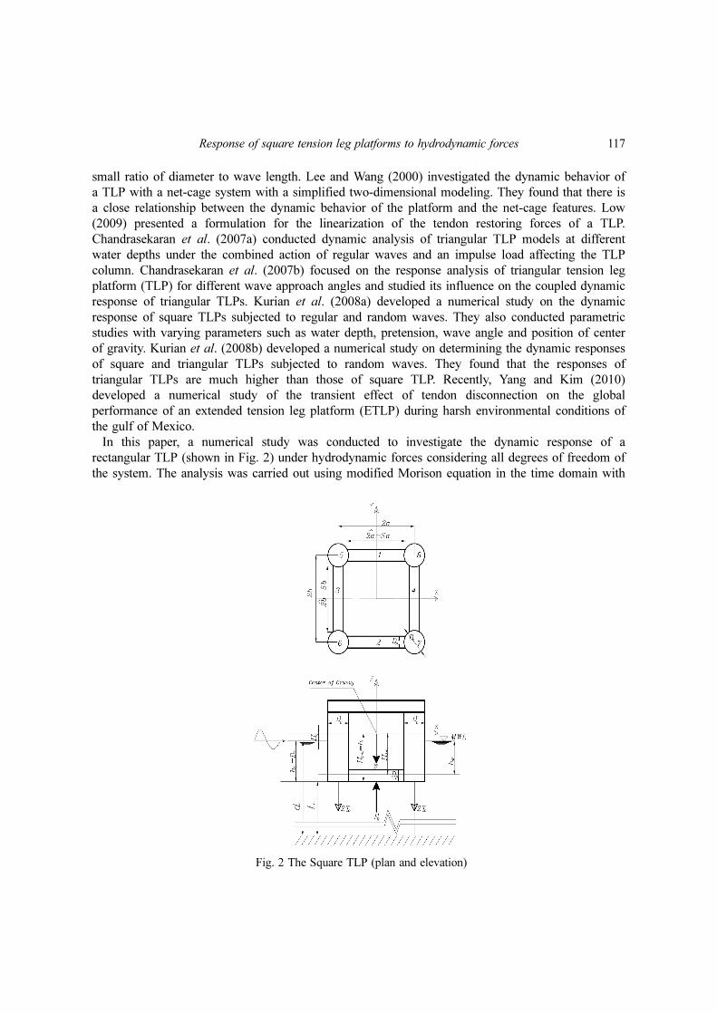
and can be determined as following
Surge (1) direction
The coefficients of the first column of the restoring force matrix are found by giving a unity x
displacement in the x-direction (surge) as shown in Fig. 3. The increase in the initial pre-tension in
each leg is given by
(7)
(8)
where A is the cross-sectional area of the tether; E is the Young’s Modulus of the tether; is the
increase in the initial pre-tension due to the arbitrary displacement given in the surge degree of
freedom; L is the length of the tether; and x1 is the arbitrary displacement in the surge degree of
freedom. Equilibrium of forces in different directions gives
(9)
(10)
(11)
(12)
T1∆E A× L∆×
L-------------------------=
L∆ x1
2L
2+ L–=
T1∆
K11
4 To T1∆+( )
x1
2L
2+
---------------------------=
K31
4To
L
x1
2L
2+
------------------- 1–⎝ ⎠⎜ ⎟⎛ ⎞
4 T1∆ L
x1
2L
2+
-------------------+
x1
-------------------------------------------------------------------------------------=
MX∑ O K41 x1 K41⇒ O= = =
K51 K11– h( )=
Fig. 3 The Surge displacement in a rectangular TLP
Response of square tension leg platforms to hydrodynamic forces 121
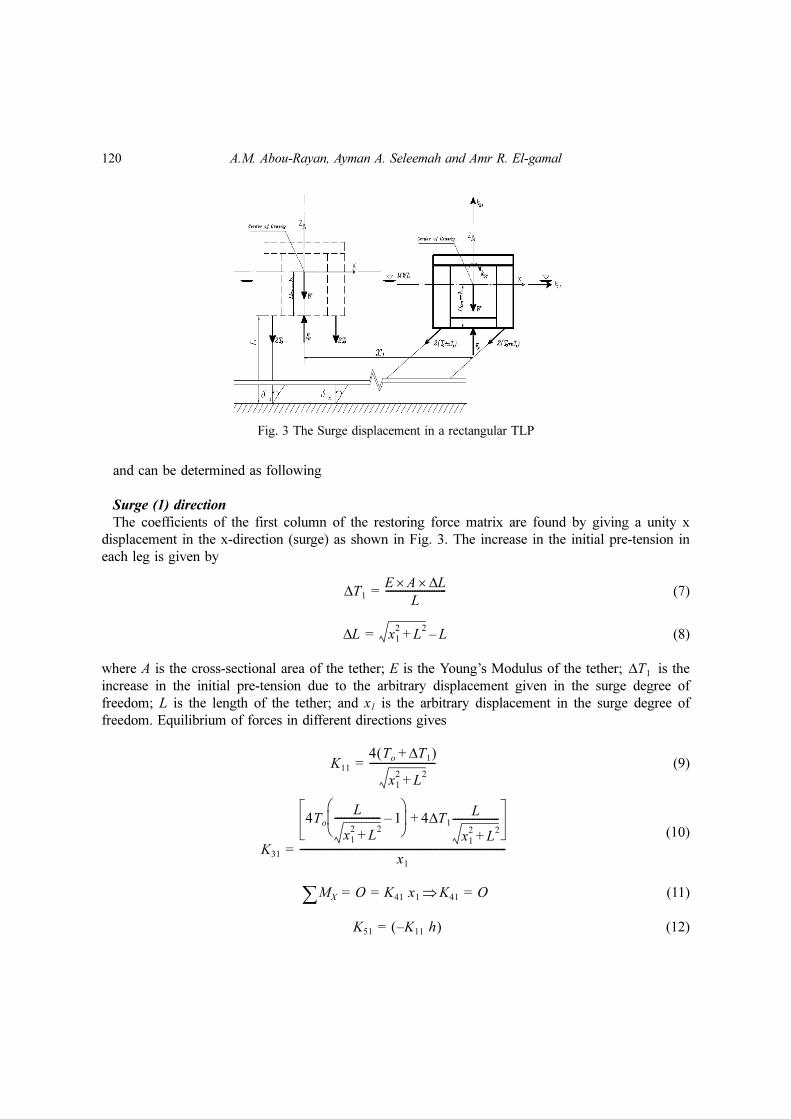
The negative sign occurs due to the counterclockwise moment, where, h is the distance between
the center of mass and the bottom of the platform (see Fig. 3).
(13)
Sway (2) direction
The coefficients of the second column of the restoring force matrix are found in a similar manner
by giving a unity y displacement in the y-direction (sway) as shown in Fig. 4.
(14)
(15)
(16)
(17)
Where ∆T2 is the increase in tension due to sway and is given by
(18)
(19)
Mz∑ O K61x1 K61⇒ O= = =
K12 0= , K52 0= and K62 0=
K22
4 To T2∆+( )
x2
2L
2+
---------------------------=
K32
4To
L
x2
2L
2+
------------------- 1–⎝ ⎠⎜ ⎟⎛ ⎞
4 T2
L
x2
2L
2+
-------------------∆+
x2
-------------------------------------------------------------------------------------=
K42 hK22–=
T2∆E A× L∆×
L-------------------------=
L∆ x2
2L
2+ L–=
Fig. 4 The Sway displacement in a rectangular TLP

122 A.M. Abou-Rayan, Ayman A. Seleemah and Amr R. El-gamal
Note that δ x and δ y shown in Figs. 3 and 4 are the angles of inclination of the cables with respect
to the vertical when under surge and sway movements, respectively.
Heave (3) direction
The third column is derived by giving the structure an arbitrary displacement in the z direction
(heave). The sum of the forces in the all directions yield
(20)
(21)
Roll (4) direction
The coefficients in the fourth column of the restoring force matrix are found by giving the
structure in arbitrary rotation x4 about the x-axis as shown in Fig. 5. Summation of the moments of
the resulting forces about the x-axis yields
K14 = K54= K64= 0 (22)
K13 K23 K43 K53 K63 0= = = = =
K33 4EA
L------- 4
πDc
2
4---------ρg+=
Fig. 5 The Roll displacement in a rectangular TLP
Response of square tension leg platforms to hydrodynamic forces 123
Taking summation of forces in y-axis we find that
(23)
By taking summation of forces about z-axis we find that
(24)
and taking summation of moments about x axis we get
(25)
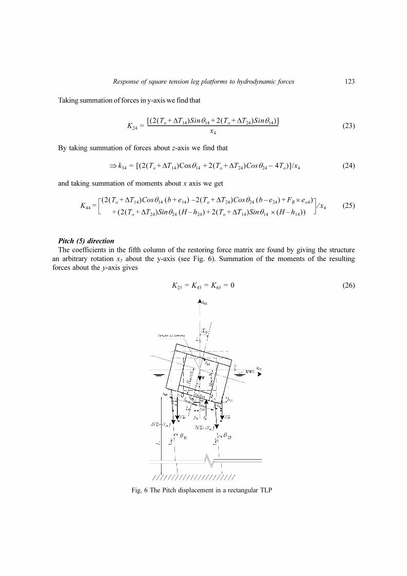
Pitch (5) direction
The coefficients in the fifth column of the restoring force matrix are found by giving the structure
an arbitrary rotation x5 about the y-axis (see Fig. 6). Summation of the moments of the resulting
forces about the y-axis gives
(26)
K24
2 To T14∆+( )Sinθ14 2 To T24∆+( )Sinθ14+( )[ ]x4
---------------------------------------------------------------------------------------------------------=
k34⇒ 2 To T14∆+( )Cosθ14 2 To T24∆+( )Cosθ24 4– To+( )[ ]/x4=
K44
2 To T14∆+( )Cosθ14 b e14+( ) 2– To T24∆+( )Cosθ24 b e24–( ) FB eo4×+( )
2 To T24∆+( )Sinθ24 H h24–( ) 2 To T14∆+( )Sinθ14 H h14–( )×+( )+= x4⁄
K25 K45 K65 0= = =
Fig. 6 The Pitch displacement in a rectangular TLP

124 A.M. Abou-Rayan, Ayman A. Seleemah and Amr R. El-gamal
Taking summation of forces in the x-direction, we find that
(27)
Taking summation of forces in the z-direction, we obtain
(28)
By taking summation of moments about y-axis then
(29)
Yaw (6) direction
By giving an arbitrary rotation x6 in the yaw degree of freedom, the sixth column of the restoring
force matrix can be obtained (see Fig. 7). We can find that
K15
2 To T15∆+( )Sinθ15 2 To T25∆+( )Sinθ25 +[ ]x5
------------------------------------------------------------------------------------------------------=
k35⇒ 2 T T15∆+( )Cosθ15 2 To T25∆+( )Cosθ25 4– T+( )[ ]/x5=
K55
2 To T15∆+( )Cosθ15 a e15+( ) 2– To T25∆+( )Cosθ25 a e25–( )
F+ B eo5× 2 To T25∆+( )Sinθ25 H h25–( ) 2 To T15∆+( )Sinθ15 H h15–( )×+( )+= x5⁄
Fig. 7 The Yaw displacement in a rectangular TLP

Response of square tension leg platforms to hydrodynamic forces 125
(30)
By taking summation of moment about z-axis we find that
(31)
Finally, through summation of forces in the vertical direction one obtains
(32)
Where is the change in tether tension force due to yaw displacement.
The overall stiffness matrix given by Eq. (6) shows
1. The presence of off-diagonal terms, which reflects the coupling effect between the various
degrees of freedom.
2. The coefficients depend on the change in the tension of the tethers, which is affecting the
buoyancy of the system. Hence, the matrix is response dependent.
Hence, during the dynamic analysis, the [K] matrix is not constant for all time instants, but its
components are continuously changing at each time step depending upon the response values at the
previous time step.
3.3 Mass matrix, [M]
The mass matrix is assumed to be lumped at each degree of freedom. Hence, it is diagonal in
nature and is constant. However, the added mass, Ma, due to the water surrounding the structural
members has been considered up to the mean sea level (MSL) and arising from the modified
Morison equation. The presence of off diagonal terms in the mass matrix indicates a contribution of
the added mass due to the hydrodynamic loading. The fluctuating components of added mass due to
the variable submergence of the structure in water is considered in the force vector depending upon
whether the sea surface elevation is above or below the MSL.
The added mass matrix of submerged portion of an arbitrarily inclined cylinder can be expressed
in terms of the direction cosines, Patel (1989). If the cylinder is located between coordinates (X1,
Y1, Z1) and (X2, Y2, Z2) relative to principal platform axis, then direction cosines can be defined as
follows
(33)
The one-half of the symmetrical added mass matrix coefficients are
(34)
K16 K26 K46 K56 0= = = =
K66 4 To T6∆+( ) a2
b2
+( )
L2
x6
2+ a
2b
2+( )
------------------------------------=
K36 4To
L
L2
x6
2+ a
2b
2+( )
------------------------------------ 1–⎝ ⎠⎛ ⎞ 4 T∆ 6
L
L2
x6
2+ a
2b
2+( )
------------------------------------⎝ ⎠⎛ ⎞+ x6⁄=
T∆ 6
AE
L-------= L
2x6
2a
2b
2+( ) L–+( )
cosαX2 X1–
L----------------, cosβ
Y2 Y1–
L---------------, cosγ
Z2 Z1–
L---------------== =
Ma11 ρCa Asin2α( ) Ld
L∫=
126 A.M. Abou-Rayan, Ayman A. Seleemah and Amr R. El-gamal
(35)
(36)
(37)
(38)
(39)
(40)
(41)
(42)
(43)
(44)
(45)
(46)
(47)
Where
(48)
(49)
(50)
(51)
(52)
Ma22 ρCa Asin2β( ) Ld
L∫=
Ma13 Ma31 L∫ ρCa Acosα cosγ( )dL–= =
Ma32 Ma23 L∫ ρCa Acos β cosγ( )dL–= =
Ma15 Ma51 Ma11Z Ma13 X–= =
Ma24 Ma22 Z Ma13Y= =
Ma33 ρCa Asin2γ( ) Ld
L∫=
Ma35 Ma53 Ma13Z Ma33 X–= =
Ma34 Ma43 Ma23Z Ma33Y–= =
Ma55 Ma11Xm
22Ma13 ZX( )m– Ma33Zm
2+=
Ma44 Ma22Ym
22Ma23 ZX( )m– Ma33Zm
2+=
Ma66 Ma22Ym
2Ma11Xm
2+=
Ma16 Ma61 = Ma11– Y =
Ma26 Ma62 = Ma22– X =
AπD
2
4---------=
XX1 X2+
2----------------=
YY1 Y2+
2----------------=
ZZ1 Z2+
2----------------=
Xm
2 X1
2X1X2 X2
2+ +
3------------------------------------=
Response of square tension leg platforms to hydrodynamic forces 127
(53)
(54)
(55)
(56)
The loading will be attracted only in the surge, heave and pitch degrees of freedom due to the
unidirectional wave acting in the surge direction on a symmetric configuration of the platform about
the x and z axes. Therefore, the mass matrix can be written as
(57)
Where, M is the mass of the body, rx, ry, and rz are the radii of gyrations about the x, y, and z-
axes, respectively.
3.4 Structural damping [C]
Damping was presented in the form of alpha and beta damping (Rayleigh Damping). The
damping matrix [C] is calculated by using alpha and beta constants as multipliers to the mass
matrix [M] and stiffness matrix [K], respectively.
(58)
The values of α and β are calculated based on typical modal damping ratios, ξi.
3.5 Hydrodynamic force vector, {F (t)} on rectangular TLP
The problem of suitable representation of the wave environment or more precisely the wave
loading is a problem of prime concern. Once the wave environment is evaluated, wave loading on
Ym
2 Y1
2Y1Y2 Y2
2+ +
3-----------------------------------=
Zm
2 Z1
2Z1Z2 Z2
2+ +
3-----------------------------------=
ZX( )m
2Z1X1 2Z2X2 Z1X2 Z2X1+ + +
6--------------------------------------------------------------------=
ZY( )m
2Z1X1 2Z2X2 Z1X2 Z2X1+ + +
6--------------------------------------------------------------------=
M[ ]
M Ma11+ 0 Ma13 0 Ma15 Ma16
0 M Ma22+ Ma23 Ma24 0 Ma26
Ma31 Ma32 M Ma33+ Ma34 Ma35 0
0 Ma42 Ma43 Mrx
2Ma44+ 0 0
Ma51 0 Ma53 0 Mry
2Ma55+ 0
Ma61 Ma62 0 0 0 Mrz
2Ma66+
=
C[ ] α M[ ] β K[ ]+=

128 A.M. Abou-Rayan, Ayman A. Seleemah and Amr R. El-gamal
the structure may be computed based on suitable theory. In this study the water particle position η
is determined according to Airy’s linear wave theory as following
(59)
Where Am is the amplitude of the wave; k is the wave number; ω is the wave frequency; x is the
horizontal distance from the origin; and ϕ is the wave phase angle. This description assumes a wave
form which have small height, H, in comparison to its wave length, λ, and water depth, d. In order
to incorporate the effect of variable submergence which is an important aspect of hydrodynamic
loading on TLP, instantaneous sea surface elevation is taken as the still water level (or water depth).
The fluctuating free surface effect can be significant when the wave height cannot be ignored
compared to the water depth.
The hydrodynamic force vector is calculated in each degree of freedom according to modified
Morison’s equation which takes into account the relative velocity and acceleration between the
structure and the fluid particles. It is also worth mentioning that the ratio d/H can be related to d/λ.
Based on the limiting heights of breaking waves, it become unstable and break when H/λ ≥ o.1, (λ
is the wave length).
(60)
and
(61)
Where As is the cross-sectional area; Cm is the inertia coefficient; U is the undisturbed fluid
velocity; Uc is the current velocity, if exist; and Cd is the drag coefficient. Note that in Eq. (60), the
first term represents the inertia force, the second term represents the drag force, and the last term
represents the added mass force. The term |U| is written in this form to ensure that the drag force
component is in the same direction as the velocity.
The components of the normal velocity and acceleration vectors for a segment of an arbitrarily
inclined cylinder can be expressed as
(62)
(63)
(64)
(65)
Where u,w and are the horizontal and vertical water particle velocities and accelerations,
respectively.
Wave and current loading naturally occur simultaneously and current direction may not coincide
with wave direction and may vary with depth. The speed may also change with depth. To present a
η x t,( ) Amcos kx ωt– ϕ–( )=
dF ρCmAs
du
dt------
dx•
dt--------–⎝ ⎠
⎛ ⎞ ρCdD Udx
dt-----– U
dx
dt-----–⎝ ⎠
⎛ ⎞ Cm 1–( )ρAsdx
•
dt--------–+=
U ud z+
d----------Uc⎝ ⎠
⎛ ⎞+=
ux u x1
• –( )sin
2α w x2
• –( )cosα cosγ–=
uz w x3
• –( )sin
2γ u x1
• –( )cosα cosγ–=
ux
•u
• sin
2α w• cosα cosγ–=
uz
•w
• sin
2γ u
• cosα cosγ–=
u• , w
•

Response of square tension leg platforms to hydrodynamic forces 129
realistic description, a profile which may vary in both magnitude and direction with depth is
considered. The current velocity is taken about 10% of wind velocity at a height of 10 m above the
water surface.
For the uni-directional wave train in the surge direction, the force vector {F (t)}, is given by
(66)
Since the wave is unidirectional, there would be no force in the sway degree-of-freedom F21 and
hence there will be no moment in the roll degree of-freedom F41. Because of the vertical water
particle velocity and acceleration, the heave degree-of-freedom would experience wave force F31.
The force in the surge direction F11 on the vertical members will cause moment in the pitch degree-
of-freedom F51. However, forces in the surge degree-of-freedom are symmetrical about the X axis
(due to the symmetry of the platform to the approaching wave) and there will be no net moment
caused in the yaw degree-of-freedom F61.
3.6. Solution of the equation of motion in the time domain
The equation of motion is coupled and nonlinear and can be written as
(67)
Eq. (67) is nonlinearly coupled, because of the presence of structural displacement, velocity and
acceleration in the right hand side of the equation. Therefore, the force vector should be updated at
each time step to account for the change in the tether tension. To achieve this response variation a
time domain analysis is carried out. The Newmark's beta time integration procedure is used in a
step wise manner. This procedure was developed by Newmark together with a family of time-
stepping methods based on the following equations.
(68)
(69)
The parameters β and γ define the variation of acceleration over time step ∆t and determine
the stability and accuracy characteristics of the method. Typical selection for γ is 1/2 and
1/6 ≤ β ≤ 1/4 is satisfactory from all points of view, including accuracy.
The two special cases of Newmark's method that are commonly used are
(1) Average acceleration method in which the value of γ is 1/2, β = 1/4 where, this method is
unconditionally stable.
(2) Linear acceleration method in which the value of γ is 1/2, β = 1/4 where, this method is
conditionally stable.
The first method was utilized in this study. The procedure of this method is summarized as
solving Eq. (69) for in terms of and then substituting for into Eqn
68 we obtain equations for and , each in terms of unknown only.
These two relations for and are substituted into Eq. (67) to solve for
after which, using Eqs. (68) and (69), and can also be calculated at each step.
F t( ) F11 F21 F31 F41 F51 F61{ }T=
M[ ] x••
t t∆+( ){ } C[ ] x•
t t∆+( ){ } K[ ] x t t∆+( ){ }+ + F t t∆+( ){ }=
x•
t t∆+( ) x•
t( ) 1 γ–( ) t∆[ ]x••
t( ) γ t∆( )x••
t t∆+( )+ +=
x t t∆+( ) x t( ) t∆( )x•
t( ) 0.5 β–( ) t∆( )2[ ]x•• x( ) β t∆( )2[ ]x
•• t t∆+( )+ + +[ ]=
x••
x••
t t∆+( ) x
t t∆+( ) x••
t t∆+( )x
•• t t∆+( ) x
• t t∆+( ) x
t t∆+( )
x•
t t∆+( ) x••
t t∆+( ) x
t t∆+( )x
•• t t∆+( ) x
• t t∆+( )
130 A.M. Abou-Rayan, Ayman A. Seleemah and Amr R. El-gamal
The following values are updated
(a) stiffness coefficients which varies with tether tension;
(b) added mass which varies with sea surface fluctuations;
(c) wave forces at the instantaneous position of the displaced structure.
4. Results and discussion
A numerical scheme was developed using MATLAB software where solution based on
Newmark's beta method was obtained. A major concern was about the effect of the coupling of the
degrees of freedom and about its rule in influencing some of the response behaviors critically. Thus,
numerical studies for evaluating the coupled and uncoupled responses of the square TLP under
regular waves have been carried out. Coupling of various degrees-of-freedom was taken into
consideration by considering the off-diagonal terms in stiffness matrix [K]. On the other hand, these
off-diagonal terms were neglected to study the uncoupling effect. Wave forces were taken to be
acting in the direction of surge degree-of-freedom. The geometric properties of the TLP and the
hydrodynamic data considered for force evaluation are given in Table 1.
Table 2 shows the coupled and the uncoupled natural time periods of the structure. It is seen that
coupling has no effect on natural time periods. It is also observed that TLPs have very long period
of vibration associated with motions in the horizontal plane (say 80 to 100 seconds). Since typical
Table 1 Geometric properties of the square TLP and load data
Water properties Platform properties
Gravity acceleration(m/sec2)
9.81 Platform weight (KN),W 280000Center of gravity above the
sea level (m), HC6.03
Water weight density (kN/m3)
10.06 Platform length (m), 2a 66.22 Tether stiffness (KN/m), γ 80000
Inertia coefficient, Cm 2 Platform width (m), 2b 66.22 Tether length (m), L 569
Drag coefficient, Cd 1Platform radius of gyration
in x-directions (m), rx32.1
Platform radius of gyration in y-directions (m), ry
32.1
Current velocity (m/sec), Uc
0Platform radius of gyration
in z-directions (m), rz33 Water depth (m), d 600
Wave period (sec), Tw6, 8, 10,
12.5, and 15Tether total force (KN), T 160000
Diameter of pontoon (m), DP
9.03
Wave height (m), Hw8, 10
and 12Diameter of
columns (m), Dc
18.06Draft(m),Dr 31
Damping ratio, ξ 5%
Table 2 Calculated natural structural periods for different analysis cases (in seconds)
Analysis CaseDOF
Surge Sway Heave Roll Pitch Yaw
Coupled 97.099 97.099 2.218 3.126 3.126 86.047
Uncoupled 97.067 97.067 2.218 3.125 3.125 86.047
Response of square tension leg platforms to hydrodynamic forces 131
wave spectral peaks are between 6 to 15 seconds, resonant response in these degrees of freedom is
unlikely to occur.
The natural periods in vertical plane in heave, roll and pitch are observed to be in the range of 2
to 4 seconds which is consistent with typical TLP's. While this range is below the periods of typical
storm waves, everyday waves do have some energy in this range (the lowest wave period for most
geographical locations is about 3 seconds). Thus, wave–excited vibrations can cause high-cycle
fatigue of tethers and eventually instability of the platform. One alternative to this problem is to
increase the moored stiffness as to further lower the natural periods in heave, roll and pitch
movement. The other alternative is to install damping devices in the tethers to mitigate vertical
motion.
Time histories of the coupled and the uncoupled responses are shown in Figs. 8 to 10. Before going
into detailed discussion for each response it is clear from the figures that the coupling has no effect on
response in the surge and heave directions where, it has negligible effect on pitch direction. This might
be attributed to the fact that the hydrodynamic loading was taken as a unidirectional regular wave
acting in the surge direction on a symmetrical configuration of the platform.
4.1 Surge response
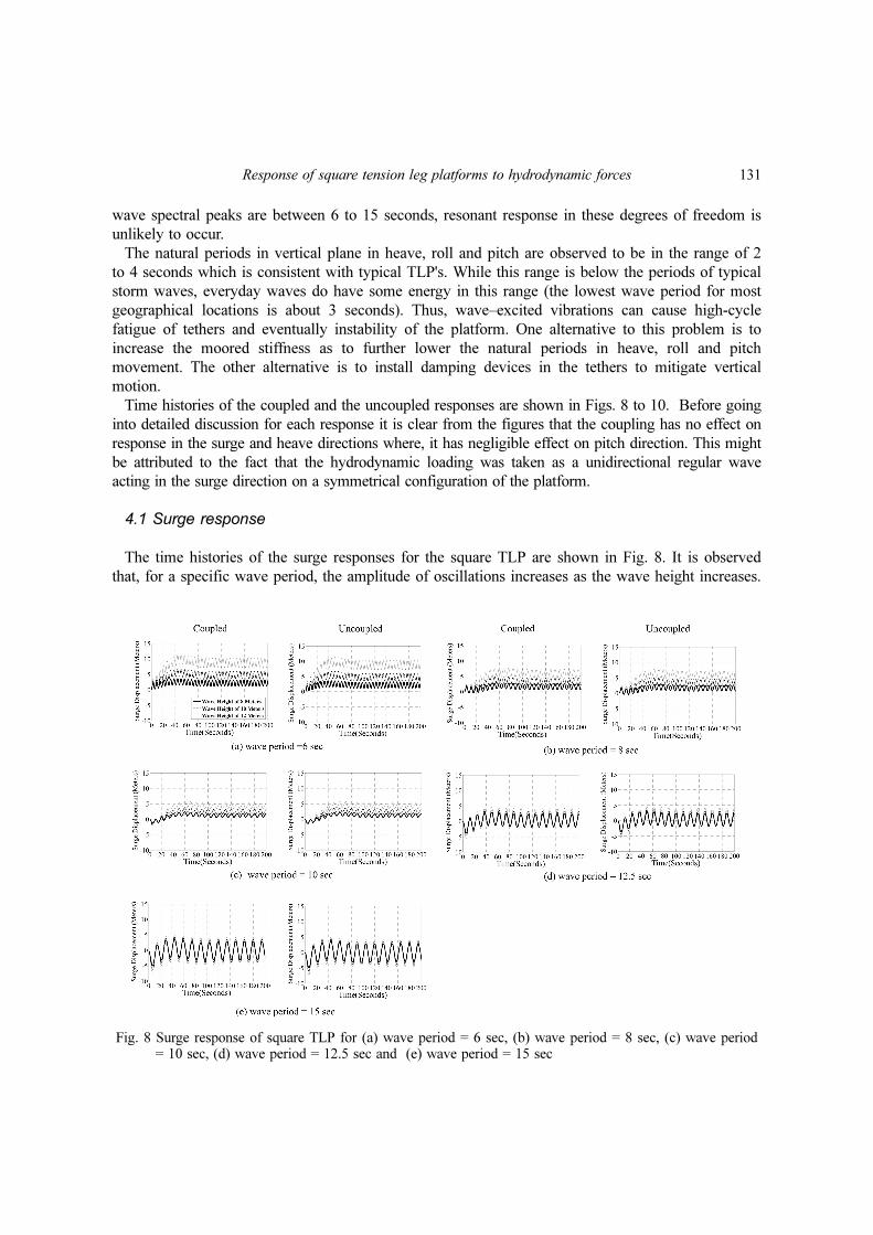
The time histories of the surge responses for the square TLP are shown in Fig. 8. It is observed
that, for a specific wave period, the amplitude of oscillations increases as the wave height increases.
Fig. 8 Surge response of square TLP for (a) wave period = 6 sec, (b) wave period = 8 sec, (c) wave period= 10 sec, (d) wave period = 12.5 sec and (e) wave period = 15 sec
132 A.M. Abou-Rayan, Ayman A. Seleemah and Amr R. El-gamal
Moreover, for short wave periods (up to 10 sec), the system responds in small amplitude oscillations
about a displaced position that is inversely proportional to the wave period and directly proportional
to wave height. On the other hand, for relatively long wave period (12.5 or 15 sec.), the system
tends to respond in high oscillations amplitude about its original position. The amplitude of
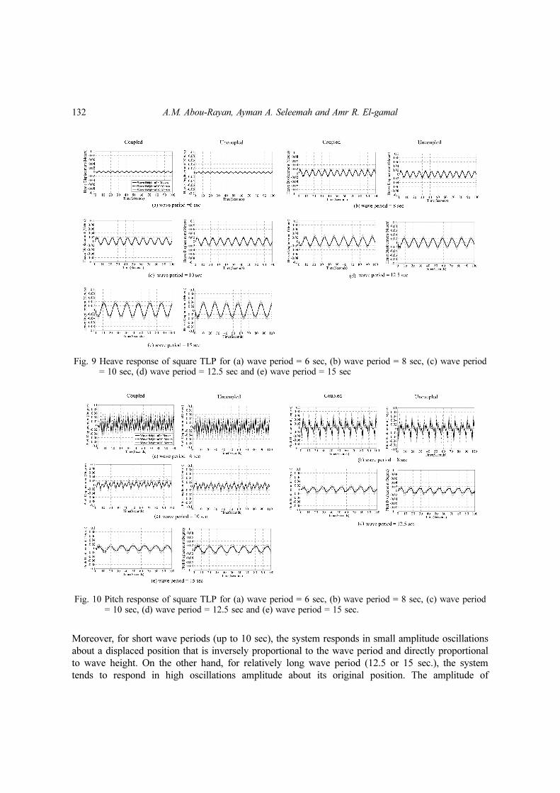
Fig. 9 Heave response of square TLP for (a) wave period = 6 sec, (b) wave period = 8 sec, (c) wave period= 10 sec, (d) wave period = 12.5 sec and (e) wave period = 15 sec
Fig. 10 Pitch response of square TLP for (a) wave period = 6 sec, (b) wave period = 8 sec, (c) wave period= 10 sec, (d) wave period = 12.5 sec and (e) wave period = 15 sec.
Response of square tension leg platforms to hydrodynamic forces 133
oscillations increases with the increase in the wave period, which is expected because as the wave
period increases, it becomes closer to the surge period of vibration (about 97 sec.). Moreover, the
effect of wave height becomes more pronounced for shorter wave periods. In all cases, the surge
response seems to have periodic oscillations that have the same exciting wave period. Finally, the
transient state takes about 40-80 seconds where the stationary state begins.
4.2 Heave response
The time histories of the coupled and the uncoupled heave responses are shown in Fig. 9. As
expected, the response in the heave direction has very small values compared to that of the surge
direction. This is attributed to the relatively high stiffness of the tethers in this direction together
with the fact that the excitation is indirect in this case. Moreover, the heave response is directly
proportional to the wave period and to a less extent to wave height. Also, the transient state takes
about 10 seconds where the stationary state begins and the motion is almost periodic. The heave
response appears to have a mean value of nearly zero.
4.3 Pitch response
The time histories of the coupled and the uncoupled pitch responses are shown in Fig. 10. It is
clear that as the wave period increases the response becomes closer to being periodic in nature. For
short wave periods (up to 10 sec.), a higher mode contribution to the response appears to take place.
For long wave periods (12.5 and 15 sec.), the higher mode contribution vanishes after one or two
cycles and we have a one period response (wave period) as in the surge and heave cases. Moreover,
the transient state takes about 20 seconds before the stationary state begins.
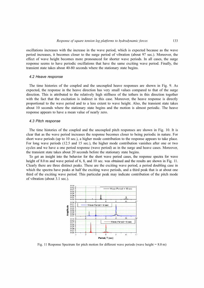
To get an insight into the behavior for the short wave period cases, the response spectra for wave
height of 8.0 m and wave period of 6, 8, and 10 sec. was obtained and the results are shown in Fig. 11.
Clearly there are three distinct peaks. These are the exciting wave period, a period doubling case in
which the spectra have peaks at half the exciting wave periods, and a third peak that is at about one
third of the exciting wave period. This particular peak may indicate contribution of the pitch mode
of vibration (about 3.1 sec.).
Fig. 11 Response Spectrum for pitch motion for different wave periods (wave height = 8.0 m)
134 A.M. Abou-Rayan, Ayman A. Seleemah and Amr R. El-gamal
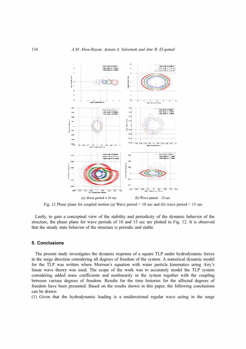
Lastly, to gain a conceptual view of the stability and periodicity of the dynamic behavior of the
structure, the phase plane for wave periods of 10 and 15 sec are plotted in Fig. 12. It is observed
that the steady state behavior of the structure is periodic and stable.
5. Conclusions
The present study investigates the dynamic response of a square TLP under hydrodynamic forces
in the surge direction considering all degrees of freedom of the system. A numerical dynamic model
for the TLP was written where Morison’s equation with water particle kinematics using Airy’s
linear wave theory was used. The scope of the work was to accurately model the TLP system
considering added mass coefficients and nonlinearity in the system together with the coupling
between various degrees of freedom. Results for the time histories for the affected degrees of
freedom have been presented. Based on the results shown in this paper, the following conclusions
can be drawn:
(1) Given that the hydrodynamic loading is a unidirectional regular wave acting in the surge
Fig. 12 Phase plane for coupled motion (a) Wave period = 10 sec and (b) wave period = 15 sec
Response of square tension leg platforms to hydrodynamic forces 135
direction on a symmetrical configuration of the platform the coupling between various degrees of
freedom is insignificant, contrary to the cases of random sea wave loads. Hence, coupling between
various degrees of freedom has no effect on the surge or the heave responses, and has an
insignificant effect on the pitch response.
(2) TLP’s have very long period of vibration (80 to 100 seconds) associated with motions in the
horizontal plane, surge, sway and yaw. Since typical wave spectral peaks are between 6 to 15
seconds, resonant response in these degrees of freedom is unlikely to occur.
(3) For short wave periods (less than 10 sec.), the surge response consists of small amplitude
oscillations about a displaced position that is inversely proportional to the wave period and directly
proportional to wave height. On the other hand, for relatively long wave period (12.5 or 15 sec.),
the system tends to respond in high oscillations amplitude about its original position.
(4) The heave response is directly proportional to the wave period and to a less extent to wave height.
(5) For short wave periods (less than 10 sec.), a higher mode contribution to the pitch response
accompanied by period doubling appears to take place.
(6) The phase plane shows that the steady state behavior of the structure is periodic and stable.
References
Bhattachatya, S.K., Anitha, J. and Idichandy, V.G. (2004), “Experimental and numerical study of coupleddynamic response of a mini-tension leg platform”, J. Offshore Mech. Arct., 126(4), 318-330.Chandrasekaran, S. and Roy, A. (2005), “Phase space study of offshore structures subjected to non-linear
hydrodynamic loading”, Proceedings of the International Conference on Structural Engineering, SEC 2005,Indian Institute of Science, Bangalore.
Chandrasekaran, S., Jain, A.K., Gupta, A. and Srivastava, A. (2007a), “Response behaviour of triangular tensionleg platforms under impact loading”, Ocean Eng., 34(1), 45-53.
Chandrasekaran, S., Jain, A.K. and Gupta, A. (2007b), “Influence of wave approach angle on TLP’s response”,Ocean Eng., 34(8-9), 1322-1327.
Denis. J.P.F. and Heaf, N.J. (1979), “A Comparison between linear and nonlinear response of a proposed tensionleg production platform”, Proceedings of the Offshore Technology Conference, OTC 3555.
Ketabdari, M.J. and Ardakani, H.A. (2005), Nonlinear response analysis of a sea star offshore tension legplatform in six degrees of freedom, WIT Transactions on the Built Environment 84.
Kurian, V.J., Gasim, M.A., Narayanan, S.P. and Kalaikumar, V. (2008a), “Parametric study of TLPs subjected torandom waves”, ICCBT-C-19, 213-222.
Kurian, V.J., Gasim, M.A., Narayanan, S.P. and Kalaikumar, V. (2008b), “Response of square and triangularTLPs subjected to random waves”, ICCBT-C-12, 133-140.
Lee, H.H. and Wang, P.W. (2000), “Analytical solution on the surge motion of tension leg twin platformstructural systems”, Ocean Eng., 27(4), 393-415.
Low, Y.M. (2009), “Frequency domain analysis of a tension leg platform with statistical linearization of thetendon restoring forces”, Mar.Struct., 22(3), 480-503.
Morgan, J.R. and Malaeb, D. (1983), “Dynamic analysis of tension leg platforms”, Proceedings of the 2ndinternational Offshore Mechanics and Arctic Engineering symposium, USA.
Patel, M.H. (1989), Dynamics of Offshore Structures, Butterworth, London.Tan, S.G. and De Boom, W.C. (1983), “The wave induced motions of a tension leg platform in deep water”,
Proceedings of the Offshore Technology Conference, OTC 4074.Taudin, P. (1978), “Dynamic response of flexible offshore structures to regular waves”, Proceedings of the
Offshore Technology Conference, OTC 3160.Yang, C.K. and Kim, M.H. (2010), “Transient effects of tendon disconnection of a TLP by hull–tendon–riser
coupled Dynamic analysis”, Ocean Eng., 37(8-9), 667-677.