resonant circuits circuits... · 2019-06-14 · chapter 1 introduction to resonance 1. review of...
TRANSCRIPT
ELECTRONIC TECHNOLOGY SERIES
a
RESONANT CIRCUITS
~ ,·~. ', ,. ·. ' . . ' -. • V .,,' . •,:·,
publication
,,

RESONANT CIRCUITS
Edited by
Alexander Schure, Ph.D., Ed. D.
$1.25
JOHN F. RIDER PUBLISHER, INC.
116 West 14th Street • New York 11, N. Y.

Copyright January 1957 by
JOHN F. RIDER PUBLISHER, INC.
All rights reserved. This book or parts thereof may not be reproduced in any form or in any language
without permission of the publisher.
Library of Congress Catalog Card No. 57-7216 ·
Printed in the United States of America
PREFACE
Arrangements of the resistor, capacitor, and inductor are found in various series, parallel, or series-parallel combinations in electronic circuits, depending upon the specific application desired. The relationships of these three components, as they are affected by a-c voltages of varying frequencies, are of particular interest when the capacitive and inductive reactances become equal, yielding a resonant circuit.
In the first chapter, we review the essential theory related to resonance. Detailed discussions then treat the theory of series resonant circuits, delineating the computations relating to resonant frequency, the voltage relationships, and the role of the figure of merit (Q) in these circuits. Similar analyses are made, first for the elements comprising parallel resonant circuits and then of the parallel resonant circuits themselves. Further analyses cover resonant circuits with distributed constants through an explanation of tuned lines. The rest of the theoretical material treats resonant coupled circuits, including the coupling coefficient, reflected impedance, and the effects of coupling upon resonance. A few basic applications are described. These are typical of the general uses of the circuits and are sufficient to give an understanding of general circuit arrangements.
Grateful acknowledgement is made to the staff of New York Technical Institute for its assistance in the preparation of this manuscript.
New York, N. Y. January 1957
A.S.
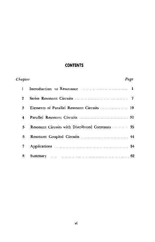
CONTENTS
Chapter
Introduction to Resonance
2 Series Resonant Circuits
3 Elements of Parallel Resonant Circuits
4 Parallel Resonant Circuits
5 Resonant Circuits with Distributed Constants
6 Resonant Coupled Circuits
7 Applications
8 Summary
vi
Page
1
7
19
30
35
44
54
62

Chapter 1
INTRODUCTION TO RESONANCE
1. Review of Theory Related to Resonance
The reader who selects a work on resonant circuits for study is assumed to be familiar with the behavior of various components in a-c circuits. The brief, but comprehensive summary of a-c theory relevant to resonance included in this chapter should help him to refresh his memory sufficiently to allow complete understanding of what follows. In the equations in this review the currents and voltages, may be instantaneous, peak, or rms provided that all values within the equation are expressed in the same terms.
2. Resistance in a-c circuits
There is no essential difference between the behavior of a resistor in either a d-c or an a-c circuit. The pertinent equations and characteristics for either circuit are:
Ohm's Law: l=E/R E=IR R=E/1
Series Connections: Rt = R1 + R2 + .... Rn
Parallel Connection: I/Rt = l/R1 + l/R2 + .... l/R11
where I is in amperes, E in volts, and R in ohms.

2 RESONANT CIRCUITS
Effect on phase: Resistors do not affect the phase relationships between current and voltage a-c circuits in any way. (See Fig. 1.)
Power dissipation (see Fig. 2) : P = 12R = El = E2 /R
3. Capacitance in a-c circuits
The opposition of a capacitor to the flow of ac is termed capacitive reactance; the magnitude of the capacitive reactance of any capacitor depends upon its capacitance, C, and the frequency, £, of the ac.
Series connection: I/Ct = l/C1 + l/C2 + .... l/C0
Parallel connection: Ct = C1 + C2 + .... C0
Capacitive reactance: Xe = l/271"fC
Ohm's law: I= E/Xc E = IXe Xe= E/1
where Xe is in ohms, f in cps, C in Farads, I in amperes, and E in volts.
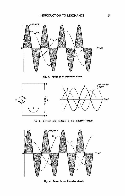
Effect on phase: The current flowing in a purely capacitive circuit always leads the applied voltage by 90 degrees. (See Fig. 3.)
Power dissipation: A purely capacitive circuit does not dissipate any power. (See Fig. 4.) If the circuit contains both capacitance and resistance, the phase angle will be less than 90 degrees and the power dissipation is:
P = El cos</>
where </> is the phase angle determined by
cot</>= 271"fRC
Charge on capacitor: Q = CE
Energy of capacitor: W =·= ½ CE2
where Q is the charge in coulombs and W is the energy in wattseconds

INTRODUCTION TO RESONANCE
E '\i R
.__ ______ a
(A) (B)
Fig. 1. Current and voltage In a resistive drcult.
X
180 ~--- ..._ 270 .,,...-'/ 360
' ---- / ' / ' / ' ,, _.,,
Fig. 2. Power In a resistive circuit.
r-------•b
E 'v
'-------•a (A) ( Bl
P (AVG.POWER I
Fig. 3. Current and voltage in a capacitive circuit.
3
X

4 RESONANT CIRCUITS
4. Inductance in a-c circuits
The opposition of an inductor to the flow of ac is called inductive reactance; its magnitude is a function of the a-c frequency and the inductance.
Series connection (no coupling): Lt = L 1 + L2 + .... l/Ln
Parallel connection (no coupling) : I/Lt = l/L1 + l/L2 + .... 1/Ln
Inductive reactance: XL= 21rfL
Ohm's law: I = E/XL E = IXr. Xr, = E/I
where XL is in ohms, f in cps, L in henrys, I in amperes, and E in volts.
Effect on phase: The current flowing in a purely inductive a-c circuit lags behind the applied voltage by 90 degrees. (See Fig. 5.)
Power dissipation: A purely inductive circuit dissipates no power. (See Fig. 6.) If the circuit contains both in
ductance and resistance, the phase angle will be less than 90 degrees and the power dissipation is
P = EI cos cf,
where cf, is the phase angle determined by Cot cf, 21rfL/R
5. Meaning of Resonance
Figure 7 shows a capacitor C, a coil L, and a resistor R connected in series with an a-c voltage source of variable frequency. In one range of frequencies X<' may be considerably larger than Xi,; in some higher frequency range Xr, may become much greater than Xr. (The resistance R remains the same for all frequencies.) At some frequency between these two ranges, an interchange of predominance occurs, and at one point the reactances of the capacitor and the inductor become equal. The voltage drops across them are then equal and 180 degrees out of phase. (This angle is the sum of the 90 degree lead of the capacitor and the 90 degree of the inductor.) Under these conditions, the reactances effectively cancel each other completely, and the current flow is determined only by the resistance of the circuit. At the frequency that establishes these
INTRODUCTION TO RESONANCE 5
TIME
Fig. 4. Power In a capacitive drcult.
,---------eb
E 'v L
,__ ______ _.a
Fig. 5. Current and voltage in an inductive circuit.
TIME
Fig. 6. Power in an Inductive drcuit.

6 RESONANT CIRCUITS
conditions - i.e. the resonant frequency - the current reaches its highest possible value (assuming a constant source voltage), a condition termed series resonance. Thus, a series circuit is said to be resonant when the inductive reactance equals the capacitive reactance.
A capacitor and inductor may also be connected in parallel across the output of an a-c generator to form a parallel resonant
E '\,
L
C Fig. 7. Series circuit con• taining resistance, capaci
tance, and inductance.
circuit in which the conditions for resonance are somewhat modified. Both series and parallel resonance are discussed in detail in subsequent chapters.
6. Review Questions
(I) What is the relationship between current and voltage waves in purely resistive circuits?
(2) What is the only a-c circuit component that can dissipate power? (3) What is the voltage-current phase relationship in a purely capacitive
circuit? in a purely inductive circuit? (4) State the equation for determining capacitive reactance; inductive re•
actance. (5) From the a-c power equation, what must be the value of the phase angle
cf, for maximum power dissipation to occur? (6) Referring to Fig. 4, explain how this diagram shows that the power
dissipated in a capacitive circuit is zero. Repeat for Fig. 6, for inductive circuits. (7) In what way does the power curve of Fig. 2 differ from those of Fig. 4
and Fig. 6 and what is the implication of this difference. (8) Calculate the inductive reactaoce of a IO-henry choke coil when used in
connection with 60-cps power lines. (9) Calculate the capacitance of the capacitor that would resonate at 60 cp1
with the inductor of Question 8. (10) What is the total reactance of a coil and capacitor combination con•
uected in series across a generator if the reactance of each is 137 ohms?

Chapter 2
SERIES RESONANT CIRCUITS
7. Indications of Series Resonance
Before prm·eeding in our study of series resonant circuits, let us find out how to determine whether a particular circuit is reso• nant. The fit-st requirement is that the capacitive reactance equal the inductive reactance. A series cirrnit c:annot be resonant if these two values are not equal.
It might be well to mention at this point that the resonant condition can be obtained by varying the value of the inductance, the capacitance, or the applied frequency. When the circuits are in resonance, the impedance of the circuit is at a minimum and is equal to the circuit resistance. The current flowing in the circuit is at its highest possible point and is in phase with the applied voltage. In addition, the circuit acts as a purely resistive circuit. The voltage across the inductance is equal to the voltage across the capacitance, and is relatively high. In fact it may exceed the supply voltage. Although numerically equal, these emf's have opposite polarity and the resultant voltage is zero.
If there is any possibility that the circuit will operate at or close to resonance, the voltage ratings of the coils and capacitors must be carefully selected to insure that the components can withstand a voltage in excess of the supply voltage. This is particularly true if the circuit resistance is low compared to the circuit reactance.
7

8 RESONANT CIRCUITS
8. Calculation of Resonant Frequency
Although coil-capacitor combinations may be designed to resonate at any frequency, resonant circuits find their widest application in the radio frequency range. The reactive effects associated with even small capacitances may impose severe limitations on the usefulness of these circuits, if the frequency is relatively high. One way of overcoming these effects is to add inductive reactance to the circuit if the effects of capacitive reactance are to be cancelled, and vice versa. A specific reactance may be detrimental to the per-
~ L 5MH EL
J
5001.JJJF
Fig. 8. Typical .. ,1e1 circuit containing R, C and L
formance of a circuit when it produces an undesirable voltage drop at a particular frequency. In this case, the insertion of a reactive component of the opposite kind gives rise to a neutralizing voltage drop 180 degrees out of phase with the unwanted one. This remedy is effective at one frequency only, since there is only one resonant point for a given pair of reactances.
The series resonant circuit is in a state of resol)ance when the inductive reactance and the capacitive reactance are exactly equal. Since this is true,
1 2..-£.,L = --
2..-f0C solving for f0 , the resonant frequency, we have
1 fo = 2..-..,/LC
Let us apply this to the circuit shown in Fig. 8. First, since we are looking for the resonant frequency, the resistance of the circuit
SERIES RESONANT CIRCUITS 9
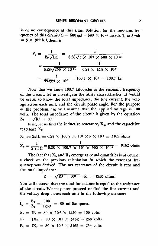
is of no consequence at this time. Solution for the resonant frequency of this circuit(C = 500wJ = 500 X 10·12 farads, L = 5 mh = 5 X 10·8 h. ), then, is
l l fo = ---,==- = -::-:--::--;:;:;:=;::===:::;::::;::=======:::::::::==
2,,.-v[c 6.28\!5 3< 10·8 X 500 X 10·12
I I = --::-::-::---===::::;::;;:::;= 6.28\!250 X 10·1' 6.28 X 15.8 X 10·7
= 99_224
IX lO-' = 100.7 X 103 = 100.7 kc.
Now that we know 100.7 kilocycles is the resonant frequency of the circuit, let us investigate the other characteristics. It would be useful to know the total impedance, the line current, the voltage across each unit, and the circuit phase angle. For the purpose of the problem, we will assume that the applied voltage is 100 volts. The total impedance of the circuit is given by the equation zT = yR2 + x2.
First, let us find the inductive reactance, Xt, and the capacitive reactance Xo.
XL= 2wfL = 6.28 X 100.7 X IOS X5 X 10·3 = 3162 ohms
I I Xo = 2 ..- f C = 6.28 X 100.7 X 108 X 500 X 10·12 = 3162 ohms
The fact that X,. and Xe emerge as equal quantities is of course, a check on the previous calculation in which the resonant frequency was derived. The net reactance of the circuit is zero and the total impedance
Z = yR2 + X 2 = R = 1250 ohms.
You will observe that the total impedance is equal to the resistance of the circuit. We may now proceed to find the line current and the voltage drop across each unit in the following manner:
I ET 100 80 ·11· T = ~ = 1250 = m1 1amperes.
Ea = IR = 80 X 10·3 X 1250 = 100 volts
EL = IXr, = 80 X 10·3 X 3162 = 253 volts
Ee = IX<. = 80 X 10·3 X 3162 = 253 volts

10 RESONANT CIRCUITS
Although EL and E,. are numerically equal, they are 180 degrees out of phase and effectively cancel each other. A voltmeter connected across the series circuit comprising the inductance and the capacitance would read zero. Note that these voltages across the reactive components in the circuit are higher than the line voltage. As stated earlier, this can happen in a series R-L-C circuit if it is operated at or close to resonance, and if the circuit resistance is low compared to inductive and capacitive reactances.
The circuit phase angle (i.e., the angle between the voltage and current vectors), is zero because the arrangement acts as if only resistance were present, the reactive voltage drops having can-
EL
Ee
ER
90°LEAD 90° ANGLE
ET Ee BETWEEN
EL Ee AND I
90°LAG ET
90° ANGLE BETWEEN EL AND I
Fig. 9. Vector diagram (left) and vectorial addition of voltage (right) for the circuit of Fig. 8.
celled each other. To see how this appears vectorially, refer to Fig. 9 in which current is used as the reference vector. The line voltage is in phase with the line current; the circuit is operating at unity power factor, and the phase angle is zero, just as if the circuit were purely resistive.
9. Voltage Relationship in Series Resonant Circuits
Referring to the circuit of Fig. IOA, let us consider the voltage relationship in a series-resonant circuit. If an a-c source of a frequency below resonance is connected to the circuit, it will be found that the greatest opposition to current flow is caused by the reactance of capacitor C, because capacitive reactance increases as the frequency of the applied voltage decreases.
If a source voltage with a frequency above resonance is applied to the circuit under consideration, the greatest opposition to the flow
SERIES RESONANT CIRCUITS 11
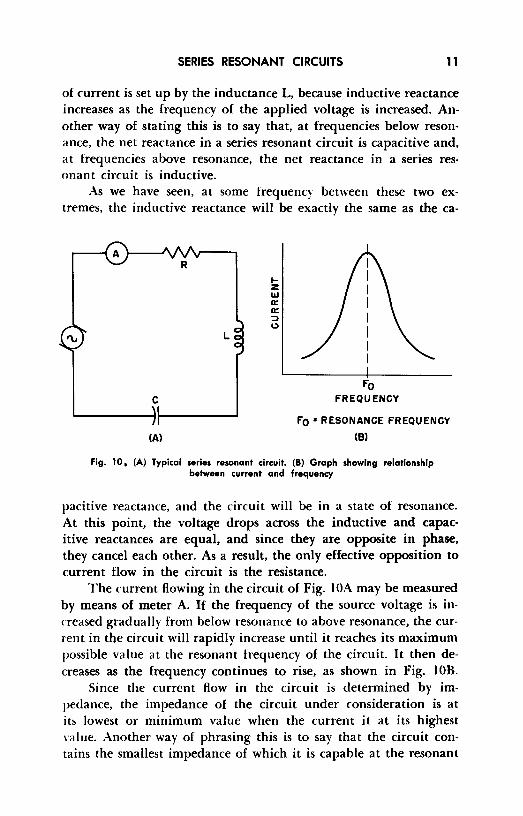
of current is set up by the inductance L, because inductive reactance increases as the frequency of the applied voltage is increased. Another way of stating this is to say that, at frequencies below resonance, the net reactance in a series resonant circuit is capacitive and, at frequencies above resonance, the net reactance in a series resonant circuit is inductive.
As we have seen, at some frequency between these two extremes, the inductive reactance will be exactly the same as the ca-
L
C
(A)
1-z l&J a: a: ::::> 0
Fo FREQUENCY
Fo s RESONANCE FREQUENCY
(Bl
Fig. 10, (A) Typical series resonant circuit. (B) Graph showing relationship between current and frequency
pacitive reactance, and the circuit will be in a state of resonance. At this point, the voltage drops across the inductive and capacitive reactances are equal, and since they are opposite in phase, they cancel each other. As a result, the only effective opposition to current flow in the circuit is the resistance.
The current flowing in the circuit of Fig. I OA may be measured by means of meter A. If the frequency of the source voltage is increased gradually from below resonance to above resonance, the current in the circuit will rapidly increase until it reaches its maximum possible value at the resonant frequency of the circuit. It then decreases as the frequency continues to rise, as shown in Fig. I OB.
Since the current flow in the circuit is determined by impedance, the impedance of the circuit under consideration is at its lowest or minimum value when the current it at its highest value. Another way of phrasing this is to say that the circuit contains the smallest impedance of which it is capable at the resonant

12 RESONANT CIRCUITS
frequency, and that the impedance rapidly increases on either side of resonance. Figure 11 shows the impedance curve for a typical series-resonant circuit.
The voltage drop across each element of a series circuit is given by a-c forms of Ohm's Law as follows:
Ea= IR E,. = IXi. Ee= IXe
At any given frequency, the reactances Xi. and Xe are fixed by the physical nature of the inductor and the capacitor, respectively, and by the frequency of the ac. These reactances are not individually modified by connecting them in series with each other to form a
Ill u z <I Q Ill IL :I!
FEREQUENCY
Fo •RESONANCE FREQUENCY
Fig. 11. Impedance curve of a .. rln-tuned drcult.
resonant circuit if the frequency is unchanged; furthermore, the current in a series circuit is everywhere the same for any given set of conditions. Hence, the voltage developed across either the inductance or capacitance considered separately attains its highest value when the circuit current is greatest, or when the total impedance is least. This situation occurs at resonance when the net reactance is zero and the circuit impedance becomes equal to the resistance. Considering either the inductive or capacitive component, what we really have is a condition in which a high current - obtainable by making the resistance, R, of the circuit small - Bows through a large reactance, thus yielding a very large voltage (IR) drop.
Although the high voltages across the individual reactances are equal and opposite in polarity at resonance (and thus tend to cancel each other from the viewpoint of the net circuit voltage), either of them may be used to operate other circuits.
If the value of either the inductance or the capacitance is changed, the resonant frequency of the circuit is changed. An increase of either capacitance or inductance, or both, will cause the
SERIES RESONANT CIRCUITS 13
resonant frequency of the circuit to become lower. Conversely, decreasing the values of capacitance or inductance or both will cause the resonant frequency of the circuit to increase. Thus we may make either the capacitance or the inductance variable. The circuit can then be resonated to any frequency over a range determined by the value of the fixed reactance and the maximum and minimum values of the variable reactance.
In practical applications, either reactance may be varied to tune the circuit. For example, in most broadcast-band receivers, tuning is done by varying the amount of capacitance in the circuit. In many television and f-m tuners tuning is accomplished by inductance variation.
In summary, we might say that when a circuit operates below its resonant frequency the capacitive reactance is greater than the inductive reactance, and the circuit acts as an R-C circuit. When the circuit operates above its resonant frequency, the inductive reactance exceeds the capacitive reactance, and the circuit acts as an R-L circuit.
10. Q of Resonant Circuits
Our discussions thus far have ignored the inherent resistance that is present, often to a large degree, in practical coils and to a much lesser extent in capacitors. The resistance of a conductor is not always the same for an alternating current as it is for direct current. A high-frequency alternating current flowing through a conductor causes internal effects that tend to force the current to flow mostly in the outer parts of the conductor, a phenomenon known as "skin effect." Skin effect decreases the effective cross-sectional area of the conductor, with an accompanying increase in resistance.
In low-frequency circuits, skin effect is often negligible. At radio-frequencies, however, it is so much greater that virtually all the current flow is confined within a depth of a few thousandths of an inch under the surface of the conductor. Radio-frequency resistance consequently may be many times the direct current resistance and continues to increase as the frequency rises. In the r-f ranges, a conductor of thin tubing may present the same resistance to current flow as a solid conductor of the same diameter.
At the higher frequencies, the relationship between the inductive reactance and the overall resistance of a given coil changes in

14 RESONANT CIRCUITS
a way dependent upon the manner in which the a-c resistance increases. The ratio of the reactance of a coil to its overall resistance is called the figure of merit or Q of the coil and is mathematically defined as:
Sinte bolh X,. and R are expressed in ohms, Q is a simple ratio and has no units. EXAMPLE: Find the Q of a coil of 0.2 mh at 2 me., if the effective resistance at that frequency is IO ohms.
Q _ 2.,,.fL _ 6.28 X 2 X 106 X 0.2 X 10-a - R - IO
2.51\~ 103 = 251.2
Since both the reactance of a coil and its a-c resistance due to skin effect increase with rising frequency, it might seem that Q must be constant for all frequencies. This is not true, however, because these two facLors do not change at the same rate. Q remains constant over a relatively small range of frequencies. Below this range, however, Q decreases because XL drops faster than R. Above this range, Q again decreases because the a-c resistance rises faster than X, ..
Effect of varying frequency near resonan~:e. If we draw a curve of the current flowing in the circuit of Fig. IOA, assuming that the voltage is constant and the frequency varies from a low to a high value, the curve would resemble one of those in the chart of Fig. 12. The shape of the resonance curve at frequencies of applied voltage near resonance is principally determined by the Q of the coil. In Fig. 12, different values of R (from IO ohms to 100 ohms) are assumed, instead of the value of 1250 ohms shown in Fig. I OA. X1,
at the resonant frequency, is 1000 ohms. This gives the circuit a minimum Q of IO, with R = 100. You will note that at frequencies at least plus or minus 15 percent away from resonance, the current is substantially unaffected by further frequency changes.
If the reactance of either the inductance or the capacitance is of the same order of magnitude as the circuit resistance (Q is low, near 1) the current decreases rather slowly from resonance in either direction. Such a circuit is said to be "broad." On the other hand,

SERIES RESONANT CIRCUITS 15
if the values of reactance are large compared to the circuit resisance (Q is high) the current decreases rapidly as the frequency moves away from resonance. Such a circuit is said to be "sharp." A sharp circuit responds a great deal more readily to signals of the resonant frequency than to signals of frequencies on either side of resonance. A broad circuit responds almost equally well to a band of frequencies around the resonant frequency. Both types of reso-
Fig. 12. Effect of R (and Q) on resonance.
1-z
1.0~--~--~---~---
.et-----+----1+----+-----1
l:! .&t-----+-----------11:: :::, I.)
Ill
~ j .4t-----+-----+-l+----+-----f Ill II:
-10 +10 PERCENTAGE DEVIATION FROM
RESONANT FREQUENCY
+20
nance curves are of great value. The sharp circuit provides great selectivity, which is the ability to respond strongly, in terms of current amplitude, at one desired frequency and to discriminate against others. The broad circuit may be used when it is necessary to obtain about the same circuit response over a band of frequencies rather than at a single frequency.
We should emphasize at this point, that while most resonant circuits in schematic diagrams show only inductance and capacitance, resistance is always present.
The source of the resistance depends upon the frequency, the type of circuit elements used, and the width of frequency pass band desired. We are interested here primarily in circuits of relatively high Q (from 50 to 500), employed in radio-frequency equipment. In such applications, it is the resistance of the wire in

16 RESONANT CIRCUITS
the coil that constitutes the major part of the circuit resistance, except at high radio frequencies. In the very high frequency (vhf) range (30-300 me) and higher, the resistance component in the capacitor often becomes appreciable, especially if the dielectric is not made of low-loss material like steatite or polystyrene.
It should be noted that the resistance between the plates (leakage resistance) of a capacitor is not analogous to the resistance of the wire in the coil. The leakage resistance of a capacitor is a parallel (or shunt) resistance, while that in the coil is a series resistance. Leakage resistance of a good capacitor is very high; resistance of a good coil is very low. To combine the resistances of the coil and capacitor in a series circuit, an equivalent series resistance of the capacitor is often used. As the leakage resistance of a capacitor increases, equivalent series resistance decreases. Equivalent series resistance is related to leakage (parallel) resistance as follows:
(Xc)2 r=~
where r is the equivalent series resistance, R, the parallel resistance, and Xe the capacitive reactance of the capacitor. This relationship is true if the frequency is high enough to make Xe large compared to R. Note that series resistance is inversely proportional to parallel resistance, as stated above. EXAMPLE: A 100-µµf capacitor, used at I me, has a leakage resistance of 10,000 ohms. What is the equivalent series resistance?
I I r = IO<' (6.28 X 10⁶ X I0-10) 2 = IO• (6.28 X 10·4) 2
I 1 =~~~ = -- = 254 ohms 39.4 X 10·4 .00394
When maximum sharpness (selectivity) is desired, the aim of the designer is to reduce the inherent resistance of the components to the lowest possible values, thereby raising the Q of the circuit.
The effect of Q on the sharpness of resonance in a circuit is shown in Fig. 13. In the curves illustrated, the frequency change is shown in percentage above and below resonance. Q's of 10, 20, 50, and 100 are shown because these values cover much of the range used in radio work. In this graph current at resonance is

SERIES RESONANT CIRCUITS 17
assumed to be the same in all cases. The lower the Q, the more slowly the current decreases as the frequency moves away from resonance.
At frequencies above 30 me, energy losses in the capacitor become an important consideration. These losses may be compared to the energy loss that would resul,t if a resistor were introduced in the circuit. As stated earlier, the· Q of a coil tends to decrease at higher frequencies and the apparent increase in circuit resistance caused by capacitor losses has the effect of further reducing Q.
1.0
. 9
i .8
I .7
a .6 Ill
5 :: Ill a: .3
.2
.I
0-20
-,...
.. ... I '\ ...
I , ,,,
"' I I'\ r-. IJ I \ r-,
, "" 0•5 ->-
,, J '\ -~
0•10 ,, "" "" ~•20
' ~ "" ~ I"' 0•100 I I
I Fo I I I -15 ·10 .5 0 +5 +10 +15 +20
PERCENTAGE DEVIATION FROM RESONANT FREQUENCY
Fig. 13. Effect of Q on resonance characteristic.
It is important to specify the Q of the circuit components at the resonant frequency so that the resonance curve of the circuit will provide either the selectivity or the bandwidth required by the circuit application.
Let us consider how to determine the voltage rise across a reactive element. When a voltage of the resonant frequency is applied to a series circuit, the potential that appears across either the inductor or the capacitor is considerably higher than the applied voltage. The current in the circ.uit is determined by the actual resistance of the inductance-capacitance combination in the circuit and may have a relatively high value. However, the same current flows through the high reactances of the inductance and capacitance and causes large voltage drops. The ratio of the reactive voltage to the applied voltage is equal to the ratio of the reactance to the re-

18 RESONANT CIRCUITS
sistance. This ratio is the Q of the circuit. Hence, the voltage acr05s either the capacitor or the inductor is equal to Q times the applied voltage.
11. Review Questions
(I) What are the indications of series resonance? (2) How may the resonant frequency of an L-C circuit be varied? (3) Explain the calculation of resonant frequency in a series-resonant circuit. (4) What is the effect of an applied voltage of lower-than-resonance-frequency
on a series R-L·C circuit? (5) What is the effect of an applied voltage of higher-than-resonance-frequen•
cy on a series R-L-C circuit? (6) How may the resistance of a series R·L-C circuit affect the bandwidth of
the circuit? (7) How may the circuit resistance of an R-L·C circuit affect the selectivity
of the circuit? (8) What is the most important consideration in designing highly selective
circuits? (9) Explain the effect of Q on the selectivity of the series-resonant circuit.
(10) How may the voltage rise across the reactances in a series circuit be determined?

Chapter 3
ELEMENTS OF PARALLEL RESONANT CIRCUITS
12. Parallel Resistive-Inductive Circuits
Before discussing parallel circuits at resonance, we will con• sider the effect of current flow on the elements of parallel circuits, starting with a parallel circuit containing resistance and inductance.
When a resistance and an inductance are connected in parallel, the line current (IT) consists of two components. The first is Ia, the current through the resistance, which is in phase with the line voltage. The second is It, the current through the inductance, which lags the line voltage by 90 degrees.
Referring to Fig. 14, we will analyze the circuit and determine the line current, the circuit phase angle, the total circuit impedance, the power dissipated by the circuit, and the equivalent series circuit.
First, we may determine the value of the inductive reactance of the coil:
X,. = 21rfL = 6.28 X 60 X 0.5 = 189 ohms.
The current in the inductor is found by Ohm's law:
120 189 0.635 amperes (lagging by 90 degrees) .
19

20 RESONANT CIRCUITS
The current in the resistor,
E Ia=~
LINE VOLTAGE
E
120V 60N
120 = 100
1.20 amperes (in phase).
LI NE CURRENT-
l
R 100.n
Fig. 14, R-L parallel circuit.
The total current thus is:
IT = t + i. (The dots indicate that vector addition must be used)
The trigonometric system for adding two vector quantities when the vectors are at right angles gives us the expression IT = -../ (Ia) 2 + (IL) 2. Hence,
Ir = -../ ( 1.20) 2 + (0.635) 2 = 1.36 amperes.
E
Fig. 15- Vector diagram for the circuit of Fig. 14.
The circuit phase angle is found in the following manner.
IL 0.635 d cf, = arc tan T. = arc tan 1.
20 = - 27.9 egrees.
The total circuit impedance, Z, may be found by Ohm's law:
E 120 Z = -- = -- = 88.2 ohms IT 1.36
Figure 15 shows the vector diagram of this circuit.

ELEMENTS OF PARALLEL RESONANT CIRCUITS 21
A pure inductance does not dissipate electric power, therefore any power loss taking place in a circuit of this kind must be due to the resistive element alone. Hence,
P = Ela = 120 X 1.20 = 144 watts.
A series circuit would produce the same effect if it had an impedance of 88.2 ohms and the impedance triangle had a circuit
77.9A
R
L 0.109H
( B)
(A)
/ /
,, /
/
Fig. 16. Equivalent circuit and impedance triangle for the circuit of Fig. U.
phase angle of 27 .9 degrees. The equivalent series circuit is shown, with its impedance triangle, in Fig. 16. The values of the circuit elements are ascertained thus:
R = Z~os cf,= 88.2 X 0.884 = 77.9 ohms
XL = Z-r5in cf,== 88.2 X 0.468 = 41.3 ohms
L _ XL = 41.3 - 27rf 6.28 X 60
0.109 henrys
This circuit is relatively straightforward because the phases of the two branch currents differ by 90 degrees. If either branch contained more than one type of circuit element, the current in that branch would have a phase angle of less than 90 degrees. This makes the solution more laborious, although the basic reasoning remains the same.
13. Resistive-Capacitive Circuits
The procedure for solving R-C parallel circuits is similar to the method discussed above for the R-L circuit. The only change

22 RESONANT CIRCUITS
is that now the current leads the line voltage by some angle less than 90 degrees. Assuming a supply voltage of 40 volts rms at 2000 kc for the circuit of Fig. 17, we will find the line current, the circuit phase angle, the power dissipated, the total circuit impedance, and the equivalent series circuit.
First, we will determine the capacitive reactances of capacitors Cl and C2 and the currents, 11 and 13 in the capacitive branches.
1 1 Xci = 2wfCl = 6.28 X 2 X 106 X 350 X 10·12 = 227 ohms.
x 1 -1
- 795 ohms. c2 = 2wfC2 - 6.28 X 2 X 106 X 100 X 10·12 -
40 = 227
= 0. I 76 amperes rms.
E 40 13 = Xc
2 =
795 = 0.0503 amperes rms.
These currents lead the applied voltage by 90 degrees. The current in the resistive branch (which is in phase with the applied voltage) is found in a similar manner:
E l2 = ~
40 = 500
= 0.08 amperes rms.
To find the total circuit current, we must add the three branch currents vectorially as shown in Fig. 17. The line current, IT, is the hypotenuse of a right triangle one leg of which represents the resistive branch current, 12, while the other leg represents the sum of the capacitive branch currents, 11 and 13• Therefore
IT = -,j (12) 2 + (11 + 13) 2 = -,j (0.08) 2 + (0.226) 1
= 0.239 amperes rms. We may also see from the vector diagram that the tangent of the circuit phase angle, cf,, is the ratio of the capacitive to the resistive component of the line current, or
0.226 cf, = arc tan
0_08
= 70.5 degrees.
From this we may say that the line current leads the line voltage by 70.5 degrees. (Previously we considered line current and voltage to be in phase. However, this is not the case for parallel circuits containing reactive branches when the applied a-c is not at the resonant frequency.) Since no power is dissipated in the capacitors, we can determine the power consumption of the circuit from

ELEMENTS OF PARALLEL RESONANT CIRCUITS 23
P = El2 = 40 X 0.08 = 3.20 watts. Finally, the total impedance of the circuit, Z, is found by
E 40 Z = ----i;- = 0.239 = 167 ohms.
An equivalent series circuit would have a total impedance of 167 ohms and cf,, the angle between the resistive and capacitive vectors, would be 70.5 degrees. Therefore,
E 40V '\,
2O00KC
j
Req = 167 cos cf, = 167 X .334 = 55.8 ohms. X"" = 167 sin cf,= 167 X .943 = 157.5 ohms
~ I
13 I I
Cl R CZ I 35O1,11.1F 50O.n IOOIIIIF Ir/
ti, t 12 h3 I
I 11 /',
I S
Iz
Fig. 17. R-C parallel circuit and vector diagram.
I I
_____ .., E
Since the reactance is capacitive, the value of a single capacitor providing the proper reactance may be found.
1 1 Ceq = 2,r£Xeci = 6.28 X 2 X 106 X 157.5 = 506 µ.µ.f.
Parallel resistance-capacitance circuits are used extensively in communication applications. Quite often such a circuit is used in series with the cathode of a vacuum tube to provide bias. Many other bypassing activities are most efficiently performed by these circuits.
14. Resistance, Inductance, and Capacitance in Parallel
In the foregoing paragraphs we have discussed circuits containing resistance and capacitance, and circuits containing resistance and inductance. Let us now consider a parallel circuit containing resistance, capacitance, and inductance. Note that the circuit of Fig. 18 has a measuring instrument connected in series with each branch and one instrument in series with all three branches. These

24 RESONANT CIRCUITS
ammeters show the total current and the current in each individual branch.
In any one branch the current would be unchanged if the other two branches were disconnected, as long as the applied voltage did not change. Hence, the total current (I) is the vector sum of the currents through all three branches. The currents through the various branches is as shown in Fig. 19, which shows the
-1
e: "' Fig. 18. R-1.-C parallel
drcult.
applied voltage shape, the current through each component, the current through the inductance and capacitance in parallel, and the total current in the circuit.
For the purposes of this explanation we are assuming that the inductive reactance is smaller than the capacitive reactance, and that the capacitive reactance is smaller than the resistance of the circuit. The current through the capacitance leads the applied volt• age by 90 degrees, and the current through the inductance lags the applied voltage by 90 degrees, so that these currents are 180 degrees out of phase. The net reactive current in the circuit is found by subtracting the current in the inductance from that in the capacitance and the total circuit current is found by adding the net reactive current and the resistive current vectorially. Note that the net reactive current is smaller than either of the currents in the reactive branches.
The total current (I) lags the applied voltage by an angle less than 90 degrees. The sum of the three branch currents is larger than the current in the resistance alone.
The impedance, looking into the circuit from the voltage source, is equal to the applied voltage divided by the line current, I. In the case we are discussing, the line current is greater than the

ELEMENTS OF PARALLEL RESONANT CIRCUITS 25
current flowing through resistance R. Since this is so, the impedance of the circuit must be less than the value of the resistance of
Fig. 19. Amplitude and phase relations in the circuit af Fig. 18.
R. (How much less depends on the reactive currenL) If the inductive reactance and the capacitive reactance are nearly equal, this reactive current will be very small since the reactive current is the difference between the values of the two currents flowing through

26 RESONANT CIRCUITS
the reactances. In such a case the impedance of the circuit will be nearly the same as the value of the resistance R alone. On the other hand, if the difference between the the reactances is great, the reactive current will be large and the total current also will be considerably larger than the value of the current flowing through the resistance R. In such a case, the value of the circuit impedance will be lower than the value of R alone.
15. Series-Parallel Circuits
A series-parallel circuit, as applied to resonance, is simply a parallel circuit with both resistance and reactance in one or both branches. Although most cases of parallel resonance are concerned only with reactive branches, one of the branches sometimes con-
"' E
lr \
\ \
le
(A)
\ \
\ \ (bl IT MIN.(CIRCUIT IMPEDANCE MAX.)
(al Ir WHEN XL• Xr
:et I I I I I I I I I I I I I I
I
(cl IT FOR POWER FACTOR OF 1
CB)
Fig. 20. Resonant conditions in a low-Q parallel drcult.
tains a resistance. This is more often true in the inductive branch circuit when the coil has a low Q. A typical illustration is a transmitter tank circuit, where a low Q is often necessary because of the load coupled to the coil. Instructions for tuning these circuits often advise tuning just off the minimum current point. This means that after final tuning adjustment the line current will not be at a minimum. The reason for this is that when a branch of a parallel circuit contains both resistance and reactance (instead of pure reactance), different characteristics of resonance occur at different frequencies, as explained below.

ELEMENTS OF PARALLEL RESONANT CIRCUITS 27
In a series-parallel circuit, resonance may be considered to occur at any one of three different frequencies as follows: (1) when the inductive reactance equals the capacitive reactance, (2) when the line current is at its minimum value, and (3) when the circuit acts as a pure resistance. As previously explained, the first condition is the requirement for series resonance, regardless of the resistance of the coil. In parallel circuits, the last condition is most commonly used as an indication of resonance. However, when the
Fig. 21. Typical parallel resonant circuit. I\, E
L
C
R
Q of the coil is fairly high, the resistance in the inductive branch is negligible compared with the reactance, and all three conditions occur at the same frequency. Since this is normally the case, we usually consider resonance for the parallel circuit to be the point at which inductive and capacitive reactance balance each other. However, the important point is that, if an appreciable resistance is introduced into either reactive branch of a parallel circuit, the circuit will be thrown out of resonance and must be retuned. Such a circuit with its vector diagram is shown in Fig. 20. Note that the vector at (a) shows the current at the frequency at which inductive and capacitive reactances are equal, (b) minimum line current, and (c) the current at the frequency at which the circuit acts as if it were purely resistive.
16. Effects of Frequency
Figure 21 shows a parallel-resonant circuit. The resistance (R) does not appear in physically separate form in the circuit, but rather, indicates the resistance present in the circuit due to the circuit elements. Since the coil and the capacitor are both connected across the line of the variable frequency source, there are

28 RESONANT CIRCUITS
two paths through which the current may flow: through the coil and through the capacitor. If the frequency of the applied voltage is below resonance, most of the current will flow in the inductance, since the reactance of the coil is small for low frequency alternating currents, and the reactance of the capacitor is high for low frequency currents. If the frequency of the applied voltage is above resonance, the greatest current flow is in the capacitive branch, because capacitive reactance is small at high frequencies and the reactance of the inductance is high at high frequencies.
17. Parallel Resonance
As previously explained, there are three separate conditions that apply at or near parallel resonance. The frequencies at which these conditions occur are different if resistance is appreciable, but the same if resistance is negligible. The three conditions are:
(1) Inductive reactance equals capacitive reactance. (2) The line current is at a minimum (i.e., impedance is max
imum). (3) Total circuit impedance is resistive and power factor = 1.
Condition (3) is defined as parallel resonance. Condition (2) is sometimes called antiresonance to distinguish it from the series resonant condition. As in the case of series circuits, the resonant frequency of a parallel circuit may be changed by varying the value of either the capacitance or the inductance in the circuit. However, unlike series circuits, the resonance point may also be changed by varying the resistance of one of the branches.
As the frequency of the applied voltage is increased above the resonant value of the circuit (condition 3) the reactance of the inductive branch increases in proportion, and the current through the inductance decreases. At the same time, the capacitive reactance decreases, developing a proportionate increase in the current in the capacitive branch. Since the reactances are no longer equal, the total current increases and leads the applied voltage. This increase in current means that the total impedance has decreased.
In other words, a parallel resonant circuit offers a maximum impedance at the resonant frequency, and less impedance to other frequencies, depending upon how far these other frequencies are from the resonant frequency. This is the characteristic of the parallel resonant circuit that we exploit most in communications

ELEMENTS OF PARALLEL RESONANT CIRCUITS 29
circuitry. Examples of this are the tuning circuit in a broadcast or communications receiver, and the "tank" circuit in a transmitter.
18. Review Questions
(I) Draw a typical R-L circuit. (2) Explain the operation of the circuit you have just sketched. (3) Explain how the phase angle of an R-C circuit may be determined. (4) Give a typical use for parallel R-C circuits. (5) Explain how the resonant frequency of a parallel R-L-C circuit may be
determined. (6) Explain the conditions possible at and near resonance in a low-Q parallel
circuit that has a resistance in one of the branches. (7) What is the effect of frequency variation on the action of a parallel res
onant circuit? (8) An inductance of 20 µh with a Q of 100 is connected in parallel with a
capacitor of 30 µµf. Compute f0
, the resonant frequency. (9) List the conditions in a pure L-C circuit at resonance, giving indi·
vidual reactances, current, and impedance.

Chapter 4
PARALLEL RESONANT CIRCUITS
19. Minimum line Current
Consider again a parallel circuit having a low Q. When the Q is below IO, resonance in a circuit such as the one shown in Fig. 20 is not easily defined. We usually consider series resonance to be the point at which inductive reactance and capacitive reactance are equal. However, in this circuit, there is a set of values for the inductive and capacitive reactance that will make the parallel impedance a pure resistance (unity power factor). This is normally defined as parallel resonance. However, with these values the impedance of the circuit will not have its maximum value.
There is a further set of values for the inductive and capacitive reactances that will cause the parallel impedance of the circuit to be at a maximum when the circuit is resonant. However, under these conditions the circuit does not present a pure resistance. Either condition could be called resonance, so for low Q circuits a distinction must be made between maximum-impedance and resistive-impedance parallel resonance. The difference between the two points becomes quite appreciable at a Q of 5 or lower.
Referring again to Fig. 20, consider what happens as the applied frequency is decreased. The inductive reactance of the coil and the impedance of the coil decrease in proportion to the change in applied frequency. This causes the current in the inductance to rise. We will assume that the phase angle of this inductive current
30
PARALLEL RESONANT CIRCUITS 31
will remain constant. This assumption is justified for a small frequency change, assuming that the effective resistance of the coil is reduced when the inductive reactance is reduced.
As the current through the inductance increases, the reactance of the capacitor also increases, thereby decreasing the current in the capacitive branch. Both of these effects together cause the circuit phase angle to decrease toward zero. Meanwhile, the resultant line current also decreases. If the frequency is reduced further, the phase angle will continue to decrease, but the line current will begin to increase. The vector for minimum line current is shown in
Fig. 20 (B~
20. Equal Reactance and Unity Power Factor Cases
At some frequency, the inductive reactance of a parallel resonant circuit equals the capacitive reactance. Since this condition is similar to the one discussed for series circuits, we know the frequency at which this condition occurs is
f = I 0 2.,,.-v"[c
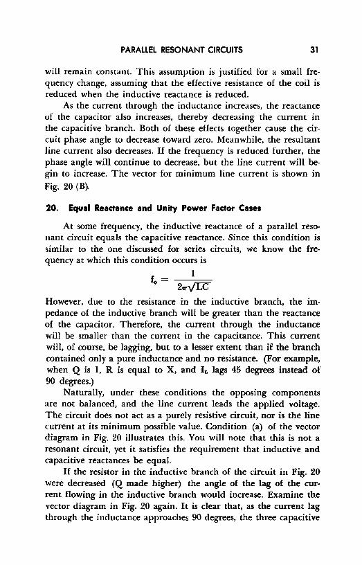
However, due to the resistance in the inductive branch, the impedance of the inductive branch will be greater than the reactance of the capacitor. Therefore, the current through the inductance will be smaller than the current in the capacitance. This current will, of course, be lagging, but to a lesser extent than if the branch contained only a pure inductance and no resistance. (For example, when Q is 1, R is equal to X, and IL lags 45 degrees instead of 90 degrees.)
Naturally, under these conditions the opposing components are not balanced, and the line current leads the applied voltage. The circuit does not act as a purely resistive circuit, nor is the line current at its minimum possible value. Condition (a) of the vector diagram in Fig. 20 illustrates this. You will note that this is not a resonant circuit, yet it satisfies the requirement that inductive and capacitive reactances be equal.
If the resistor in the inductive branch of the circuit in Fig. 20 were decreased (Q made higher) the angle of the lag of the current flowing in the inductive branch would increase. Examine the vector diagram in Fig. 20 again. It is clear that, as the current lag through the inductance approaches 90 degrees, the three capacitive
32 RESONANT CIRCUITS
current lines fall into coincidence. Certainly, if the Q of the coil were as high as 20 (the lag of IL = 87 degrees), it would be very difficult to distinguish between the three separate currents.
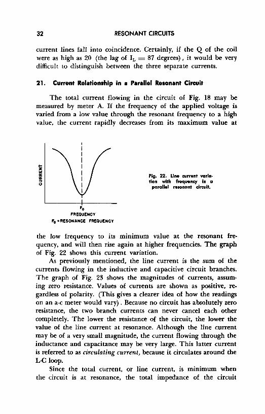
21. Current Relationship in a Parallel Resonant Circuit
The total current flowing in the circuit of Fig. 18 may be measured by meter A. If the frequency of the applied voltage is varied from a low value through the resonant frequency to a high value, the current rapidly decreases from its maximum value at
!z ... a: a: :::, ..,
Fo FREQUENCY
Fo • RESONANCE FREQUENCY
Fig. 22. Line current variation with frequency in a
parallel resonant circuit.
the low frequency to its mm1mum value at the resonant frequency, and will then rise again at higher frequencies. The graph of Fig. 22 shows this current variation.
As previously mentioned, the line current is the sum of the currents flowing in the inductive and capacitive circuit branches. The graph of Fig. 23 shows the magnitudes of currents, assuming zero resistance. Values of currents are shown as positive, regardless of polarity. (This gives a clearer idea of how the readings on an a-c meter would vary) . Because no circuit has absolutely zero resistance, the two branch currents can never cancel each other completely. The lower the resistance of the circuit, the lower the value of the line current at resonance. Although the line current may be of a very small magnitude, the current flowing through the inductance and capacitance may be very large. This latter current is referred to as circulating current, because it circulates around the L-C loop.
Since the total current, or line current, is minimum when the circuit is at resonance, the total impedance of the circuit

PARALLEL RESONANT CRCUITS 33
at this time is at its maximum value. The impedance diminishes rapidly as the frequency is varied in either direction from resonance.
If a fixed frequency signal is applied to the circuit of Fig. 18, variation of capacitor C results in a variation of the line current (ammeter reading) as the circuit impedance changes. Mini• mum line current indicates that a maximum circulating current is
t 1-z "' 0: a: :::, (,)
FREQUENCY-
Fig. 23. Magnitude of current flow in the branches of a parallel resonant circuit. (R=O)
flowing in the parallel tuned circuit. A parallel resonant circuit is quite often tuned in this manner, by watching for a dip in the line current ammeter reading.
22. Selectivity and Bandwidth
The selectivity of a parallel resonant circuit depends upon the amount and distribution of resistance in the circuit. For instance,

34 RESONANT CIRCUITS
if the circuit has a larger resistance in one of the reactive branches than in the other, the selectivity of the circuit will be impaired. For this reason, resistance may be deliberately introduced in a parallel resonant circuit to provide a more nearly symmetrical, but reduced resonance response. Normally, the resistance inherent in the circuit provides all the resistance necessary to provide these characteristics; in fact, it is sometimes difficult to design a circuit having a low enough resistance (hence a high enough selectivity) for its intended use.
23. Review Questions
(1) Why is parallel resonance in a low Q circuit not easily defined? (2) What is the parallel resonance formula for minimum line current in a
low Q circuit? (!I) What determines the value of the line current in a parallel circuit? (4) Why cannot the two branch currents in a parallel circuit cancel each
other completely? (5) How does high Q affect a parallel circuit? (6) What happens to the impedance of a parallel circuit when tuned to
resonance? /7) How may the resonant frequency of a parallel circuit be varied? (8) What determine- the selectivity and bandwidth of a parallel resonant
circuit?

Chapter 5
RESONANT CIRCUITS WITH DISTRIBUTED CONSTANTS
24. General lnfdnnation
A resonant arrangement, particularly one in which Q is high, is recognized by input impedance considerations, equality of inductive and capacitive reactance, high tank currents, or any other of the identifying characteristics discussed in the previous chapters. Up to this point, requirements for resonance have been discussed from the standpoint of lumped constants; that is, real coils and capacitors, physically recognizable as such.
Resonance may also be obtained by using distributed constants; in circuits of this nature, either the wound coil or the standard capacitor, or both, may be absent. The L-C components are represented by parallel rods or wires, specially fabricated devices like butterfly tuners, the metallic parts of certain transmitting tubes, etc. In this chapter we shall be concerned only with the use of tuned lines as distributed L-C constants.
25. Distinction Between Tuned and Untuned Lines
A tuned (or resonant) line may be defined as an essentially lossless pair of wires whose input impedance varies with frequency in a fashion that closely resembles that of a lumped-constant circuit. During operation, a resonant line contains standing waves (or stationary waves) in which voltage loops (maxima) and volt-
35

36 RESONANT CIRCUITS
age nodes (minima) are found at rather well defined, evenly spaced points along the line.
If an alternating voltage is impressed across the input terminals of a two-wire line of infinite length, a current will flow from the generator into the line even though the latter is open-circuited all along its length. The presence of the current is due to the capacitance between the wires while the magnitude of the current is determined by the distributed inductance, resistance, capacitance, and leakage between the wires. Treating the line as a lumped· constant circuit for comparison purposes enables us to state that:
E1 Zo =-,-
where E1 is the input voltage, I is the current flowing from the generator into the line, and Z0 (measured in ohms when E1 is in volts and I in amperes) is called the characteristic impedance of the line.
An infinitely long line can have no reflections of voltage or current from its remote end, a condition that is implicit in the very concept of infinity. If the line is cut to finite length and terminated in an impedance equal to its characteristic impedance, there will again be no reflections. Since the output end of the finite line "looks into" an impedance that is the exact equivalent of the infinite length just cut off, the line behaves in exactly the same manner as it did when it was of infinite length. A line of this kind is called nonresonant or untuned.
A resonant line, on the other hand, is a two-wire system of finite length not terminated in its characteristic impedance. Since such a terminating impedance does not simulate an infinite line, much of the energy that arrives at the remote end is not absorbed; instead, it is reflected hack along the line toward the generator resulting in voltage and current loops and nodes.
26. Wavelength vs. Length of Tuned Lines
Basing our reasoning on the universal power equation P = 12R, complete reflection of the energy reaching the remote end of a two-wire line is possible if: (a) the terminating impedance is infinitely great - i.e. an open circuit - since no current and hence no power can appear in such an impedance; (b) if the terminating

RESONANT CIRCUITS WITH DISTRIBUTED CONSTANTS 37
impedance is zero - i.e. a short circuit - for, under these conditions, R is zero, P must be zero, and there is again no absorption of energy in the load; or (c) if the terminating impedance is either
Fig. 24. Open-circ:uited lines.
VOLTAGE DISTRIBUTION
(A)
CURRENT DISTRIBUTION
5). 4 (B)
pure inductance or pure capacitance, in which case R is again zero. Since tuned lines used for reception and transmission systems almost always use either a short-circuited or open-circuited termination, we shall confine our discussion to these two cases.

38 RESONANT CIRCUITS
Consider first, an open-circuited two wire line 5/4 of a wavelength long1 across which any alternating voltage is impressed. Due to 100 percent reflection of the energy and the accompanying interference (re-inforcement and cancellation) along the line, voltage and current nodes and loops will appear at specific points. Assuming a lossless line, the voltage at the open end must be the same as that of the generator peak, since the voltage drop across an infinite impedance is always equal to the generator voltage. The loops and nodes thus take up positions as shown in Fig. 24A; voltmeters connected at various points as illustrated would read maximum, minimum, or intermediate values depending upon their position. It should be emphasized that the curves of Fig. 24A are not portrayals of waves; they are graphs of instrument-read voltage variations along the line due to standing waves.
In contrast with the voltage distribution, the current loops and nodes are displaced by 90 degrees. The reason for this is eveident if it is remembered that the current at the termination must be zero since it is an open circuit at this point. The current distribution is illustrated in Fig. 24B. From this, it is logical to conclude that the impedance of the line is minimum where the current is maximum (points A, C, and E in Fig. 24B) and that the impedance is maximum where the current is minimum (points B, D, and F in Fig. 24B).
The question of whether the generator end or the remote end of the line determines the voltage and current distribution is now answerable. Clearly, the distribution is a function of the conditions at the remote end, since it here that current-voltage maxima and minima are established. It is therefore conventional to measure line lengths from the remote end.2
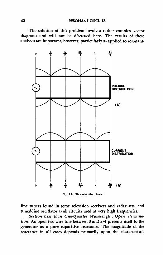
Now consider a short-circuited two-wire line, again 5/4 A. in length. At the short-circuited termination, the voltage must be zero because there can be no voltage drop across zero resistance,
t The physical length of a 5/4>. line is based, of course, upon the frequency of the alternating voltage impressed at the generator end. For example, if the frequency of the a-c is 100 me.,>. = 3 meters (wavelength = 3 X l08 meters/ frequency in cps) and a 5/4 >. line would then be 3.75 meters in length.
2 Although the open-circuited line in Fig. 24, shorts out the generator, it is simple to bypass this difficulty by assuming a small resistive gienerator impedance in series with the generator. In this case, the open-circuited line still looks like a short circuit at the source and the corresponding maximum current flows through the generator impedance to produce a voltage drop which is equal to the generator voltage.

RESONANT CIRCUITS WITH DISTRIBUTED CONSTANTS 39
and the current must he maximum. On this basis, the distribution is as shown in Fig. 25.
27. Line Resonance
Open lines. 1£ a generator is connected across a two-wire open line at a distance ,\/4 from the remote end (on the line labelled ,\ in Fig. 24) and if the rest of the line is removed, the generator will then look into the quarter-wave section and see, at the point of connection: (a) maximum current and (b) minimum impedance. As far as the generator is concerned, it is then looking into a series resonant circuit, because these current-impedance conditions together with the resonant rise of voltage from the quarter-wave point toward the remote end are typical of the behavior of series resonant arrangements. Again, if the generator is now moved to the ,\/2 point (3,\/4 line in Figure 24) it sees minimum current and maximum impedance; this is the equivalent of connecting the generator to a parallel resonant circuit. Thus, a quarter-wave open line may be used to replace a lumped-constant series resonant circuit and a half-wave open line may be used in place of a lumped-constant parallel resonant circuit.
Shorted lines. Since the voltage-current distribution is displaced 90 degrees in the case of short-circuited lines as compared with open lines (Fig. 25) , connecting the generator at one-quarter wavelength from the shorted end is the same thing as presenting it with a parallel resonant circuit; at one-half wavelength the generator sees a series resonant circuit. Thus, a quarter-wave shorted line may replace a lumped-constant parallel resonant circuit, whereas, a half-wave shorted line is equivalent to a lumped-constant series resonant circuit.
The same thinking is applicable to multiples of quarter-wavelength and half-wavelength lines as is apparent from Figs. 24 and 25.
28. Reactance of Lines Longer and Shorter than Quarter-Waves.
From the foregoing it is clear that line sections that are multiples of quarter-waves behave as either series or parallel resonant circuits depending upon actual length and termination. This brings up the question of the behavior of longer or shorter lines for both open-and shorted-circuited terminations.
RESONANT CIRCUITS
The solution of this problem involves rather complex vector diagrams and will not be discussed here. The results of these analyses are important, however, particularly as applied to resonant-
0
0
Fig. 25. Short-circuited lines.
VOLTAGE DISTRIBUTION
(A)
CURRENT DISTRIBUTION
~,_ (B)
line tuners found in some television receivers and radar sets, and tuned-line oscillator tank circuits used at very high frequencies.
Section Less than One-Quarter Wavelength, Open Terminaiion: An open two-wire line between O and .V4 presents itself to the generator as a pure capac1t1ve reactance. The magnitude of the reactance in all cases depends primarily upon the characteristic

RESONANT CIRCUITS WITH DISTRIBUTED CONSTANTS 41
impedance of the line and secondarily upon whether the line is closer to O or ,\/4 in length.
Section Less than One-Quarter Wavelength, Shorted Termination: When the termination is a short-circuit, such a section behaves as a pure inductive reactance.
Section More than One-Quarter Wavelength but Less than One-Half Wavelength, Open Termination. This arrangement presents a pure inductive reactance to the generator.
Section More than One-Quarter Wavelength but Less than One-Half Wavelength, Shorted Termination. Such a section presents a pure capacitive reactance to the generator.
29. Summary Table of Tuned line Characteristics
The chart given below is intended to assist the reader in determining the effect of a given line at a glance.
TABLE l
Equivalent Impedance
Length
Less than ,\/4
Exactly ,\/4
From ,\/4 to ,\/2
Exactly ,\/2
Open Circuit Termination
Capacitor
Series resonant circuit
Inductor
Parallel resonant circuit
30. Application to Tuned-Line Oscillators
Short Circuit Termination
Inductor
Parallel resonant circuit
Capacitor
Series resonant circuit
As mentioned before, distributed constant resonant circuits consisting of tuned lines are used in both reception and transmission equipment, in radar, and in industrial applications. Fundamentally, all of these uses involve similar principles, so that only one will be discussed, the tuned-line oscillator, chosen because of its simplicity and straight-forwardness.

42 RESONANT CIRCUITS
The oscillator circuit whose schematic is shown in Fig. 26, is a tuned-plate, tuned-grid type with resonant lines replacing the lumped L-C components usually found in low frequency oscillators.
Let us assume (for the moment) that the interelectrode capacitances of the tubes are very small. To tune the grid circuit to the desired frequency, the resonant lines between the two grids should each be exactly one-quarter wavelength, terminatd in a short circuit. As shown in Table l, such lines appear as the parallel resonant
GRID LINE
PLATE LINE
SHORTING
BAR A t--'11~'--+-.Jv'V\,--+--+--, a+
LESS LESS ____ T!N _____ _,__ _______ Ttt_AN-4 4
Fig. 26. A push-pull tuned-plate tuned-grid oscillator using tuned llnes.
circuits required for tuning. But our original assumption cannot he correct, since, for a tuned-plate tune-grid oscillator to operate, feedback must occur from output to input via the grid-to-plate capacitance of the tube. Since the grid-to-plate capacitance is in parallel with the lines, we can establish resonance at the same desired frequency by making the lines just inductive enough to tune the grid-to-plate capacitance to that frequency. As Table I shows, this requires that the lines he slightly shorter than one-quarter wavelength; thus, the desired frequency is obtained by sliding the shorting bar (A in Fig. 26) a little closer to the grids.
The normal tuned-plate tuned-grid oscillator plate circuit must be tuned to a somewhat lower frequency than that of the oscillation frequency. This means that the plate lines must be inductive. Again this is accomplished by sliding the plate circuit shorting bar (B in Fig. 26) closer to the plates than one-quarter wavelength to permit the plate-cathode capacitance to become a part of the tuned
RESONANT CIRCUITS WITH DISTRIBUTED CONSTANTS 43
circuit. Frequencies of several hundred megacycles are easily realized with this oscillator when it is used in conjunction with high frequency tubes.
31. Review Questions
(I) How does a tuned line differ from other types of resonant circuits? (2) Define characteristic impedance. (3) What is the difference between a resonant and a nonresonant line? (4) What are standing waves? (5) How do standing waves arise? (6) What factors determine voltage and current distribution in a tuned line? (7) Give an application in which a tuned line would be preferable to a
lumped-constant resonator. (8) Why is a tuned line preferable in the application given in Question 7? (9) How does the interelectrode capacitance in the tube of a high-frequency
tuned-plate tuned-grid oscillator affect the tuning of its resonant lines? (10) How is the required change in Question 9 accomplished?
Chapter 6
RESONANT COUPLED CIRCUITS
32. Importance of Coupled Circuits
The behavior of a resonant circuit may be seriously changed when it is coupled to another circuit that absorbs energy from it. The method of coupling, the extent to which power is withdrawn, and the method whereby the absorbed energy is dissipated all contribute to the moification of performance that may be expected.
Multistage equipment in which coupling between resonant circuits is encountered may be found in many diversified applications. Television and radio receivers, radar apparatus, transmitters, and industrial control circuits depend upon resonant coupling for many of their functions. In this chapter we shall be concerned only with the ways in which inductive coupling affects the performance of L-C arrangements at or near the resonant frequency.
33. Mutual Inductance
Basically, mutual inductance is an electrical property associated with a pair of coils placed so that the magnetic flux from one links with the turns of the other. (See Fig. 27.) It may be rigorously defined as a condition in which a variation of current magnitude or direction in one coil induces a voltage across the turns of the second coil.
44

RESONANT COUPLED CIRCUITS .45
Mutual inductance, M, like self inductance, L, is measured in henrys and is defined by the equation:
M E. = 2'1rflp
where M is the mutual inductance in henrys, E. the voltage induced in the secondary in volts, f the frequency of the primary current in cps, and 11, the intensity of the primary current in amperes. (It
Fig. 27. An inductively coupled circuit.
PRIMARY
Ip
SECONDARY - __ -,
D u»>!~ I ____ __.
'-_,-J M
is customary to refer to the winding in which the initial current flows as the primary winding and the coil in which the induced voltage appears as the secondary winding.) EXAMPLE: Assume that two coils are so placed that a primary current of 0.5 amperes at 60 cycles per second causes 50 volts to appear across the secondary winding. The mutual inductance between the two coils is thus:
M 50
6.28 X 60 X 0.5 .27 henrys
From a qualitative point of view, it is evident that the amount of mutual inductance between two coils may be changed in several ways: (a) by changing the distance between windings; (b) by changing the axial angle of one coil with respect to the other; and (c) by changing the manner in which coupling is accomplished, i.e., by placing the coils end to end, one above the other, winding one coil between the separate turns of the other, using tubing for one coil and winding the other inside the hollow tube, etc. The relationships that govern the mutual inductance of these arrangements are complicated and will not be discussed here, but they do lead to the question of what constitutes "close" and "loose" coupling - an important question indeed.

46 RESONANT CIRCUITS
34. Coupling Coefficient
When every flux line from a primary coil carrying an alter• nating current links with the turns of the secondary, the mutual inductance is maximum and is called unity coupling. For this theoretical condition, the mutual inductance Mmax may be expressed by the equation:
Mmax = V LpLs
where Lp is the primary inductance and L. the secondary inductance, both in henrys.
In practical circuits, unity coupling is impossible to obtain; the degree to which coupling is actually accomplished is, therefore, defined as the ratio between the true mutual inductance and the theoretical maximum, or:
k= M V LpLa
where M is the actual mutual inductance between two coils and k is the coefficient of coupling. EXAMPLE: A certain 60 cycle isolation transformer used for medium power applications has equal primary and secondary inductances of IO henrys. If the mutual inductance between windings is 9.4 henrys, what is the coefficient of coupling?
k 9.4 = 91.04 = .94 (or 94%) V IO X 10
In this case, the coupling is close to "unity" - a condition that is quite often encountered in power transformer design. In air core coils, however, such as those found in radio-frequency devices, coupling of k = .5 is considered very close while loose coupling is represented by figures like .008 or .01.
35. Reflected Impedance
The coupled circuit of Fig. 27 has a closed secondary winding; that is, the primary voltage EP causes a current Ip to flow in the primary coil which then induces a voltage E. across the secondary winding. I. is the current that flows in the secondary coil as a result of E •. Mutual inductance is a two-way affair and works just as well from secondary back to primary as the other way around.
RESONANT COUPLED CIRCUITS 47
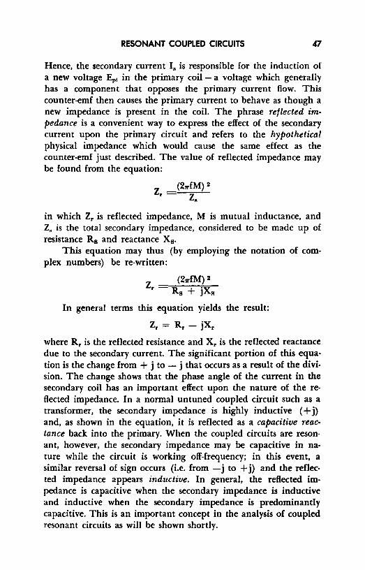
Hence, the secondary current I. is responsible for the induction of a new voltage Ep1 in the primary coil - a voltage which generally has a component that opposes the primary current flow. This counter-emf then causes the primary current to behave as though a new impedance is present in the coil. The phrase reflected impedance is a convenient way to express the effect of the secondary current upon the primary circuit and refers to the hypothetical physical impedance which would cause the same effect as the counter-emf just described. The value of reflected impedance may be found from the equation:
z. (211'fM) 2
z. in which Z, is reflected impedance, M is mutual inductance, and z. is the total secondary impedance, considered to be made up of resistance Rs and reactance Xs.
This equation may thus (by employing the notation of complex numbers) be re-written:
z. (211'fM) 2
Rs + jXR
In general terms this equation yields the result:
Z, = R, - jX,
where R, is the reflected resistance and X, is the reflected reactance due to the secondary current. The significant portion of this equation is the change from + j to - j that occurs as a result of the division. The change shows that the phase angle of the current in the secondary coil has an important effect upon the nature of the reflected impedance. In a normal untuned coupled circuit such as a transformer, the secondary impedance is highly inductive ( + j) and, as shown in the equation, it is reflected as a capacitive reactance back into the primary. When the coupled circuits are resonant, however, the secondary impedance may be capacitive in nature while the circuit is working off-frequency; in this event, a similar reversal of sign occurs (i.e. from -j to + j) and the reflected impedance appears inductive. In general, the reflected impedance is capacitive when the secondary impedance is inductive and inductive when the secondary impedance is predominantly capacitive. This is an important concept in the analysis of coupled resonant circuits as will be shown shortly.

48 RESONANT CIRCUITS
EXAMPLE: (See Fig. 28.) A mutual inductance of .02 henrys exists between a pair of coupled coils; the impedance of the secondary coil is 30 ohms and the frequency is 400 cps. What is the impedance reflected into the primary winding?
Z _ (6.28 X 400 X .02) 2
r - 30
Z _ (50.24) 2 _ 2524.0
r -30
- 30 = 84.l ohms
36. Effect of Coupling upon Resonance
Change of resonance curves with coupling. Suppose a circuit such as that shown in Fig. 29 is arranged to permit variation of coupling between Li, and L,. at various frequencies. Starting with
'-v--" M•.02 HENRIES
Fig. 28. Circuit for illustrative example.
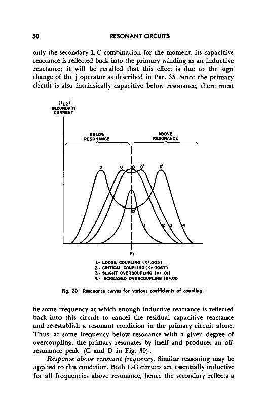
very loose coupling between the coils (k = .001 to .005), the frequency of the generator is varied above and below the resonant frequency Fr· As shown in the diagram, the two resonant circuits are identical in every respect, the Q of each being greater than 100. The loose coupling condition yields a response curve such as (I) in Figure 30 having these characteristics: (a) reduced secondary current as contrasted with the other curves due to inadequate flux linkage between primary and secondary, (b) relatively peaked top at resonance, a desirable condition for sharp tuning, (c) steeply sloped sides at frequencies near Fr on each side of resonance. This last attribute makes for good selectivity or rejection of closely adjacent frequencies when the circuit is used for receiver tuning.
As the coils L1, and L,. are moved closer together to increase the coupling from k = .003 to k = .0067, the secondary current increases as a result of the improved flux linkage, the curve (2 in Fig. 30) broadens somewhat and at the same time takes on more

RESONANT COUPLED ORCUITS 49
gently sloped sides. If the coupling is increased beyond this point, the curve (3 in Fig. 30) begins to develop double peaks which spread farther apart (curve 4) as the circuits go from slight overcoupling to increased overcoupling. The coupling coefficient for the condition which provides maximum response with a single peak - that is, curve 2 - is called the critical coupling coefficient.
Rp Cp
G T
G E Lp Ls Rs
M
Lp•Ls Cp•Cs Rp•Rs Qp•Os >100
Fig. 29. Coupling of identical series resonant drcuits.
The amount of mutual inductance necessary to arrive at critical coupling depends upon the Q's of the two resonant circuits as will be demonstrated later.
Response below resonant frequency. An understanding of the cause of the variation of the resonance curves requires application of the facts discussed in Par. 35. When the generator frequency is below resonance, the inductive reactances in the circuits are no longer equal to the capacitive reactances, the latter being the larger in magnitude. That is, a series L-C circuit below its resonant frequency behaves as a predominantly capacitive circuit. Considering
50 RESONANT CIRCUITS
only the secondary L-C combination for the moment, its capacitive reactance is reflected back into the primary winding as an inductive reactance; it will be recalled that this effect is due to the sign change of the j operator as described in Par. 35. Since the primary circuit is also intrinsically capacitive below resonance, there must
lILzl SECONOARY CURRENT
BELOW RESONANCE
Fr
ABOVE RESONANCE
1.- LOOSE COUPLING (K•.0051 2.- CRITICAL COUPLING (K•.00671 5.- SLIGHT OVEIICOUPUNG (K• .Oil 4.- INCREASED OVERCOUPUNG (k•.05
Fig. 30. Resonance curves for various coefflcienh of coupling.
be some frequency at which enough inductive reactance is reflected back into this circuit to cancel the residual capacitive reactance and re-establish a resonant condition in the primary circuit alone. Thus, at some frequency below resonance with a given degree of overcoupling, the primary resonates by itself and produces an offresonance peak (C and D in Fig. 30) .
Response above resonant frequency. Similar reasoning may be applied to this condition. Both L-C circuits are essentially inductive for all frequencies above resonance, hence the secondary reflects a
RESONANT COUPLED CIRCUITS 51
capacitive reactance back into the primary. At some frequency higher than Fr• then, the effective inductive reactance of die primary is neutralized by the reflected capacitive reactance producing the off-resonance peaks C, C~ D, and D' in Figure 30.
Response at resonance - With both circuits fed the resonant frequency F., reactance completely vanishes leaving only resistances RI and R2. Since there is no reactance in the secondary, only resistance appears as reflected impedance, adding to the resistance already present in the primary. This does not change the resonant frequency of either circuit so that resonance is theoretically present at F,. It should be noted, however, that the magnitude of the response at F, for the overcoupled curve (D'') is substantially less than that of the two off-frequency peaks (D and D'). This is easily explained as follows: for the over-coupled condition, M (in the equation Z, = (27rfM) 2 /Z.) is so large that the resistance coupled back into the primary is appreciably larger than the reflected resistances for the off-frequency cases. This increased reflected resistance reduces the primary current and hence the secondary current at F,.
37. Conditions for Critical Coupling
If the coupling between two resonant circuits is adjusted for critical coupling it is found that the reflected impedance is a pure resistance having the same value as the primary resistance. This establishes a condition of matched impedances in which Rp is effec• tively matched to R. through the medium of reflected resistance; thus, this is also the condition in which maximum power is trans• £erred from the primary to the secondary - a fact that accounts for the high peak at B in curve 2 to Fig. 30. For critical coupling, the equation Z, = (27rfM) 2 ;z. may be rewritten as
or
(a)
(27rfM) 2
R.
Note that Rs rather than Zs is used in this equation because the circuits are in resonance and the only impedances present are resistive in nature.

52 RESONANT CIRCUITS
We are interested in deriving the value of the coefficient of critical coupling (call this kcc) in terms of other common quantities. To do this, let us write several other equations as follows:
(b) Qp 21rfLP (Q of the primary, by the
RP standard definition of Q)
(c) Q,. = 21r£L,. (Q of the secondary, by the R. standard definition of Q)
(d) k M definition of k obtained in
V LpL. Paragraph 34.)
Solving equations (b) and (c) for RP and R., respectively, we have:
(e)
(f)
These values of R1, and R. are now substituted in equation (a):
(g)
Simplifying:
(h)
(i)
21rfM=
V Lp L. 21rfM = 21rf---:;::::;;:==~ v Qp Q..
M V Lp L.
v Qp Q..
Converting equation (d) to
(j)
Substituting equation (j) into equation (i) yields
(k)
Which simplifies to
(l)
RESONANT COUPLED CIRCUITS 53
Thus, equation (l) demonstrates that the coefficient of critical coupling is an inverse function of the square root of the product of the primary and secondary Q's. Thus, in circuits of high Q the coefficient of coupling may be smaller (and the coupling looser) to realize critical coupling.
The value of kee as shown in Fig. 30 was obtained from equation (l) by assuming that both Q1, and Qs were equal to 150. Then:
I y 150 X 150
38. Review Questions
1 150
.0067
(1) State three ways in which the coefficient of coupling between two given coils may be alterd.
(2) If the inductance of the primary winding of a certain transformer is 2 henrys and its secondary inductance is 50 henrys, what is the value of M for unity coupling?
(8) What is the coefficient of coupling in the transformer of Question 8 if M is actually 9 henrys.
(4) Explain briefly why reflected impedance is inductive when the secondary circuit is predominantly capacitive.
(5) Define coefficient of coupling in terms of actual mutual inductance and unity coupling.
(6) Explain clearly what is meant by critical coupling between resonant circuits.
(7) In terms of the discussion in the preceding chapter, why are overcoupled resonant circuits often used to provide wide bandpass tuning arrangements?
(9) State one advantage of loose coupling; state one disadvantage. Discuss these advantages and disadvantages in relation to a tuned circuit in the intermediate frequency stage of a superheterodyne receiver.
(9) Explain why critical coupling may be obtained in high Q circuits with less flux linkage between primary and secondary than in low Q circuits.

Chapter 7
APPLICATIONS
39. Series and Parallel Feed
Figure 31 shows three separate arrangements for a tuned-plate oscillator. Circuits (A) and (B) use series feed, and circuit (C) uses parallel feed. In circuits (A) and (B) , note that the oscillator, tuned circuit, and B+ supply are connected in series. The direct current flows through the inductance to reach the tube. This circuit works because the impedance of the d-c supply is bypassed by C2, whose reactance is so law at radio frequencies that it does not impede the flow of r-f currents. Likewise, the d-c resistance of the coil is so low that it does not impede the flow of plate de. In these applications, the tuned circuits are used to determine and select the oscillation frequency for the circuit.
Figure 31 (C) shows a parallel-feed (or shunt-feed) oscillator circuit. This circuit is usually preferred in receivers because the tuning capacitor may be directly grounded without any need for additional blocking capacitors. Tight coil coupling is important in all these circuits, since it helps maintain frequency stability when the supply voltage fluctuates. L, is made as small as possible to reduce the mutual inductance, and to keep its resonant frequency well above the tuning range. This means that stray capacitances across the feedback winding must be kept to a minimum. This circuit is not satisfactory above about 50 me. Figure 32 shows how a resonant circuit may be used to provide boosting in an amplifier. The circuit in (A) provides boosting in the vicinity
54

APPLICATIONS 55
of the resonant frequency, with maximum boost at the resonant frequency. For this type of application, the resonant frequency is often between 50 and 120 cps, although higher or lower frequencies may be used. Note that the inductor (LI) has to carry the greater part of the plate current for VI. In all circuits of this type, it is
B+ B+
RI B+
( C)
Fig. 31. Typical tuned-plate oscillators.
advisable to select a high L/C ratio in order to give the highest gain with a fixed amount of boosting.
An alternative arrangement that has the advantage of avoiding direct current flow through the winding of the inductance is shown in circuit (B) . In this application, the tuned circuit is in the grid circuit of V2. As a result, it is possible to use a higher value of L (because d-c saturation is avoided), and to shunt the tuned circuit with a variable resistor.
40. 1-F Amplifiers
Let us consider the use of resonant circuits in the design of intermediate-frequency amplifiers. The intermediate-frequency am-
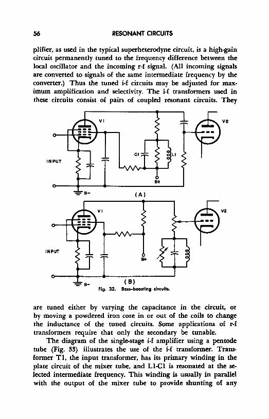
56 RESONANT CIRCUITS
plifier, as used in the typical superheterodyne circuit, is a high-gain circuit permanently tuned to the frequency difference between the local oscillator and the incoming r-f signal. (All incoming signals are converted to signals of the same intermediate frequency by the converter.) Thus the tuned i-f circuits may be adjusted for maximum amplification and selectivity. The i-f transformers used in these circuits consist of pairs of coupled resonant circuits. They
VI V2
LI INPUT
B+
(A)
V2
INPUT
B+
-:- B- ( B) Fig. 32. Bass-boosting circuits.
are tuned either by varying the capacitance in the circuit, or by moving a powdered iron core in or out of the coils to change the inductance of the tuned circuits. Some applications of r-f transformers require that only the secondary be tunable.
The diagram of the single-stage i-f amplifier using a pentode tube (Fig. 33) illustrates the use of the i-f transformer. Transformer Tl, the input transformer, has its primary winding in the plate circuit of the mixer tube, and LI-Cl is resonated at the selected intermediate frequency. This winding is usually in parallel with the output of the mixer tube to provide shunting of any
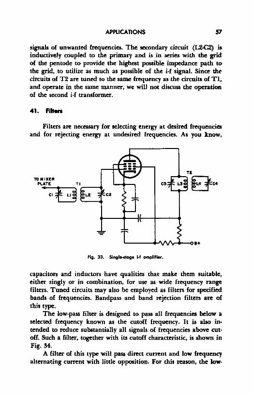
APPLICATIONS 51
signals of unwanted frequencies. The secondary circuit (L2-C2) is inductively coupled to the primary and is in series with the grid of the pentode to provide the highest possible impedance path to the grid, to utilize as much as possible of the i-f signal. Since the circuits of T2 are tuned to the same frequency as the circuits of Tl, and operate in the same manner, we will not discuss the operation of the second i-f transformer.
41. Filters
Filters are necessary for selecting energy at desired frequencies and for rejecting energy at undesired frequencies. As you know,
Fig. 33. Single-stage 1-f amplifier.
capacitors and inductors have qualities that make them suitable, either singly or in combination, for use as wide frequency range filters. Tuned circuits may also be employed as filters for specified bands of frequencies. Bandpass and hand rejection filters are of this type.
The low-pass filter is designed to pass all frequencies below a selected frequency known as the cutoff frequency. It is also intended to reduce substantially all signals of frequencies above cutoff. Such a filter, together with its cutoff characteristic, is shown in Fig. 34.
A filter of this type will pass direct current and low frequency alternating current with little opposition. For this reason, the low-

58 RESONANT CIRCUITS
pass filter is often used to filter, or smooth, the output of rectifiers of power supplies.
The high-pass filter is designed to pass currents of all frequencies above cutoff frequency. Note in Fig. 35 that this type of filter is merely a reversal of the components in the low-pass filter.
L
,.:. '000' •t OU:PUT
0-----... --0
!i ICUT·OFF 1111 1111 1-----, I FREQUENCY i~r I ~o :::,> D.11:: PASS !;0 BANO 0 -FREQUENCY
Fig. 34. Low-pass filter.
Since signals of all frequencies below cutoff are attenuated, this type of filter may, in some applications, be used to stop the flow of direct current, without stopping alternating currents above the cutoff frequency.
When higher current selectivity is required in the filter, resonant circuits may be used for filtering. The bandpass filter shown
C
0 I INPUT L OUTPUT
-,REOUENCY
Fig. 35. High-pass filter.
I
I I
PASS -,I BAND
I
in Fig. 36 is designed to pass frequencies within a continuous band, which is limited by upper and lower cutoff frequencies. The series and parallel resonant circuits of which this filter is composed are all tuned to the frequency band desired. The series resonant circuit provides a low impedance path for the signals of desired frequencies, while the parallel resonant circuits provide a low impedance path for the signals of undesired frequencies. The parallel circuit

APPLICATIONS 59
also presents a high impedance to the desired signal. These circuits are extensively used in communications receivers and transmitters.
A band-reject filter is designed to attenuate signals of all frequencies within a preselected bandwidth and to pass signals of all frequencies on either side of the attenuated band. Again, all reso-
INPUT
LOWER CUT·OFF
FFtEO
PASS BAND
UPPER CUT·OFF
FREO I I I I I I
-FREQUENCY
Fig. 36. Bandpau filter.
OUTPUT
nant circuits are tuned to the band to be affected. The parallel circuits present a high impedance to the signals of undesired frequencies only, while the series circuits present a low impedance path for these signals. Signals of frequencies outside the reject band find a low impedance path through the parallel circuit. Figure 37 is a schematic of a circuit of this type.
42. Wave Traps
Wave traps are often used in the antenna circuits of radio receivers and are, in essence, a form of the band-reject filter. Figure

60 RESONANT CIRCUITS
38 shows two basic wave traps. The parallel circuit (A) , connected as shown, is tuned to be resonant at the frequency of an undesired signal. The wave trap then presents a high impedance
0
I0 I 0 .. z
~~] .... ::,~ u .J
INPUT OUTPUT ,-o ::,> Q."' ~o
I I 0
0 0
FREQUENCY
Fig. 37 Band• stop filter.
to all signals of this frequency, and allows signals of frequencies on either side of the resonant frequency to enter the receiver.
The series circuit (B) connected as shown, is tuned to be resonant at the frequency of the undesired signal, which is then by-
~ 0 1 0
I E1N EouT E1N EouT
0 0 (A) ( B)
Fig. 38. Basic wave traps.
passed, usually to ground, without effecting the currents of other frequencies. Wave traps are often employed between amplifier stages in television receivers to eliminate unwanted signals.
43. lecher Unes
Lecher lines are lengths of parallel two-wire transmission line that are used as tuned circuit elements for obtaining wavelength measurements. These lines are normally between 2 and 5 wavelengths long. A shorting bar may be moved over the length of the
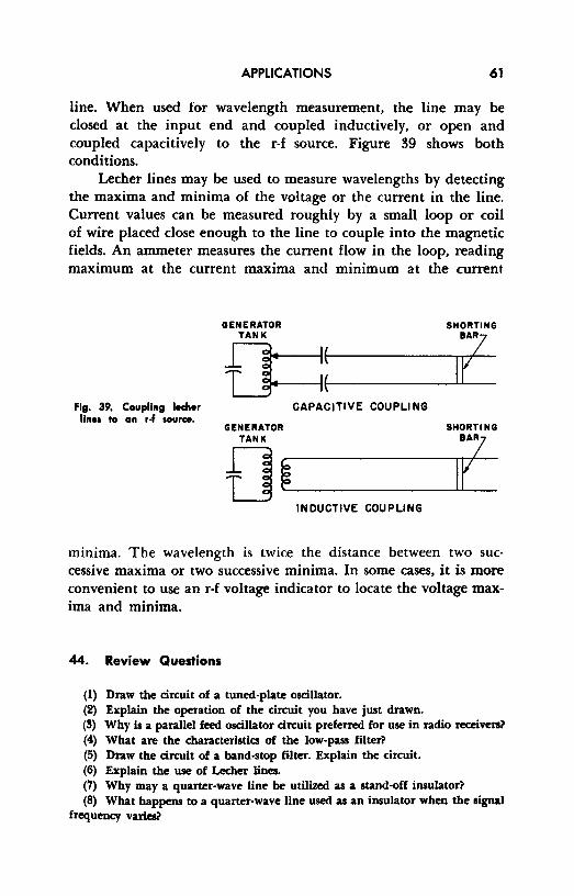
APPLICATIONS 61
line. When used for wavelength measurement, the line may be closed at the input end and coupled inductively, or open and coupled capacitively to the r-f source. Figure 39 shows both conditions.
Lecher lines may be used to measure wavelengths by detecting the maxima and minima of the voltage or the current in the line. Current values can be measured roughly by a small loop or coil of wire placed close enough to the line to couple into the magnetic fields. An ammeter measures the current flow in the loop, reading maximum at the current maxima and minimum at the current
Fig. 39, Coupling lecher lines to on r.f source.
GENERATOR SHORTING TANK BAZ
Q=j_: _....___If CAPACITIVE COUPLING
GENERATOR SHORTING TANK BAZ
f] ~.____ _ _____._I.....__P INDUCTIVE COUPLING
mm1ma. The wavelength is twice the distance between two successive maxima or two successive minima. In some cases, it is more convenient to use an r-f voltage indicator to locate the voltage maxima and minima.
44. Review Questions
(1) Draw the circuit of a tuned-plate oscillator. (2) Explain the operation of the circuit you have just drawn. (!I) Why is a parallel feed oscillator circuit preferred for use in radio receivers? (4) What are the characteristics of the low-pass filter? (5) Draw the circuit of a hand-stop filter. Explain the circuit. (6) Explain the use of Lecher lines. (7) Why may a quarter-wave line be utilized as a stand-off insulator? (8) What happens to a quarter-wave line used as an insulator when the signal
frequency varies?

Chapter 8
SUMMARY
45. Characteristics of R-L-C Circuits in General
R-L-C circuits are always resonant at some frequency. Circuit characteristics and component behavior depend principally upon whether or not the circuit is used with signals of resonant frequency. The highlights of R-L-C circuits are outlined below, with specific references to the condition of resonance (use at resonance frequency) or non-resonance (use at other than resonance frequency) as the case may be.
A. The voltage across the inductor and the voltage across the capacitor are 180 degrees out-of-phase (assuming no resistance). This phase relationship permits arithmetic subtraction of one from the other to obtain the resultant voltage across both components.
B. The current through the inductor is opposite in phase to that in the capacitor. Again, the 180-degree phase difference makes it possible to find the net reactance of the reactive components by arithmetic subtraction.
C. The current flowing in a series R-L-C circuit has the same magnitude throughout and, when used as a reference vector in a voltage vector diagram, is considered as a constant for the circuit. Thus the current vector shoul be considered as the reference line for the vector diagram.
62
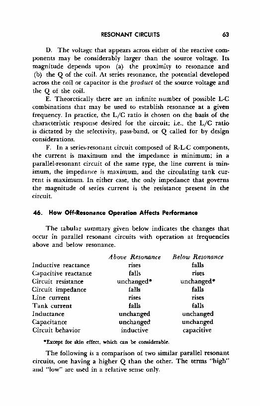
RESONANT CIRCUITS 63
D. The voltage that appears across either of the reactive components may be considerably larger than the source voltage. Its magnitude depends upon (a) the proximity to resonance and (b) the Q of the coil. At series resonance, the potential developed across the coil or capacitor is the product of the source voltage and the Q of the coil.
E. Theoretically there are an infinite number of possible L-C combinations that may be used to establish resonance at a given frequency. In practice, the L/C ratio is chosen on the basis of the characteristic response desired for the circuit; i.e., the L/C ratio is dictated by the selectivity, pass-band, or Q called for by design considerations.
F. In a series-resonant circuit composed of R-L-C components, the current is maximum and the impedance is minimum; in a parallel-resonant circuit of the same type, the line current is minimum, the impedance is maximum, and the circulating tank current is maximum. In either case, the only impedance that governs the magnitude of series current is the resistance present in the circuit.
46. How Off-Resonance Operation Affects Performance
The tabular summary given below indicates the changes that occur in parallel resonant circuits with operation at frequencies above and below resonance.
Above Resonance Below Resonance Inductive reactance rises falls Capacitive reactance falls rises Circuit resistance unchanged• unchanged• Circuit impedance falls falls Line current rises rises Tank current falls falls Inductance unchanged unchanged Capacitance unchanged unchanged Circuit behavior inductive capacitive
•Except for skin effect, which can be considerable.
The following is a comparison of two similar parallel resonant circuits, one having a higher Q than the other. The terms "high" and "low" are used in a relative sense only.
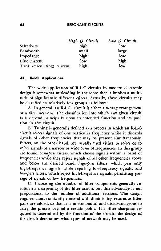
Selectivity Bandwidth Impedance Line current
RESONANT CIRCUITS
High Q Circuit high small high low
Tank (circulating) current high
47. R-L-C Applications
Low Q Circuit low
large low high low
The wide application of R-L-C circuits in modern electronic design is somewhat misleading in the sense that it implies a multitude of significantly different effects. Actually, these circuits may be classified in relatively few groups as follows:
A. In general, an R-L-C circuit is either a tuning arrangement or a filter network. The classification into which any given circuit falls depend principally upon its intended function and its position in the circuit.
B. Tuning is generally defined as a process in which an R-L-C circuit selects signals of one particular frequency while it discards signals of other frequencies that may be present simultaneously. Filters, on the other hand, are usually used either to select or to reject signals of a narrow or wide band of frequencies. In this group are found bandpass filters, which choose signals within a band of frequencies while they reject signals of all other frequencies above and below the desired band; high-pass filters, which pass only high-frequency signals, while rejecting low-frequency signals; and low-pass filters, which reject high-frequency signals, permitting passage of signals of low frequencies.
C. Increasing the number of filter components generally results in a sharpening of the filter action, but this advantage is not proportional to the number of additional sections. The design engineer must constantly contend with diminishing returns as filter pairs are added, so that it is uneconomical and disadvantageous to carry the process beyond a certain point. The filter sharpness required is determined by the function of the circuit; the design of the circuit determines what types of network may be used.
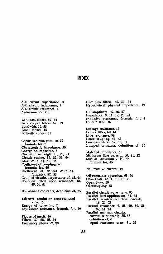
INDEX
A-C circuit capacitance, 3 A-C circuit inductance, 4 A-C circuit resistance, I Antiresonance, 28
Uandpass filters, 57, 64 Band-reject filters, 57, 59 Bandwith. 15, 33 Broad circuit, 15 Butterfly tuners, 35
Capacitive reactance, IO, 22 formula for, 2
Characteristic impedance, 36 Charge on capacitor, 2 Circuit phase angle, 10, 22, 23 Circuit tuning, 13, 26, 33, 64 Close coupling, 45, 46 Coefficient of coupling, 46
formula for, 46 Coefficient of critical coupling,
formulas, 52, 53 Coupled circuits, importance of, 43, 44 Coupling, effect upon resonance, 48,
49, 50, 51
Distributed constants, definition of, 35
Effective conductor cross-sectional area, 13
Energy of capacitor, 2 Equivalent resistance, formula for, 16
Figure of merit, 14 Filters, 57, 58, 59, 64 Frequency effects, 27, 28
65
High-pass filters, 58, 59, 64 Hypothetical physical impedance, 47
1-F amplifiers, 55, 56, 57 Impedance, 9, 11, 12, 20, 24 Inductive reactance, formula for, 4 Infinite line, 36
Leakage resistance, 16 Lecher lines, 60, 61 Line resonance, 39 Loose coupling, 45, 46 Low-pass filters, 57, 58, 64 Lumped constants, definition of, 35
Matched impedance, 51 Minimum hne current, 30, 31, 32 Mutual inductance, 44, 45
formula for, 45
Net reactive current, 24
Off-resonance operation, 63, 64 Ohm's law, ac, I, 12, 19, 22 Open lines, 39 Overcoupling, 51
Parallel circuit wave traps, 60 Parallel feed applications, 54, 55 Parallel resistive-inductive circuits,
19, 20, 21 Parallel resonance, 6, 28, 29, 30, 31,
32, 33 ,34 Parallel resonant circuits:
current relationship, 112, 113 definition of, 6 equal reactance cases, 31, 32
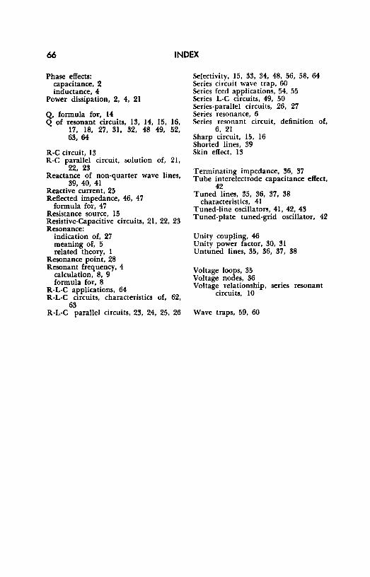
66 INDEX
Phase effects: capacitance, 2 inductance, 4
Power dissipation, 2, 4, 21
Q, formula for, 14 Q of resonant circuits, 13, 14, 15, 16,
17, 18, 27, 31, 32, 48 49, 52, 63, 64
R-C circuit, 13 R-C parallel circuit, solution of, 21,
22, 23 Reactance of non-quarter wave lines,
39, 40, 41 Reactive current, 25 Reflected impedance, 46, 47
formula for, 47 Resistance source, 15 Resistive-Capacitive circuits, 21, 22, 23 Resonance:
indication of, 27 meaning of, 5 related theory, I
Resonance point, 28 Resonant frequency, 4
calculation, 8, 9 formula for, 8
R-L-C a1;>plications, 64 R-L-C circuits, characteristics of, 62,
63 R-L-C parallel circuits, 23, 24, 25, 26
Selectivity, 15, 33, 34, 48, 56, 58, 64 Series circuit wave trap, 60 Series feed applications, 54, 55 Series L-C circuits, 49, 50 Series-parallel circuits, 26, 27 Series resonance, 6 Series resonant circuit, definition of,
6, 21 Sharp circuit, 15, 16 Shorted lines, 39 Skin effect, 13
Terminating impedance, 36, 37 Tube interelectrode capacitance effect,
42 Tuned lines, 35, 36, 37, 38
characteristics, 41 Tuned-line oscillators, 41, 42, 43 Tuned-plate tuned-grid oscillator, 42
Unity coupling, 46 Unity power factor, 30, 31 Untuned lines, 35, 36, 37, 38
Voltage loops, 35 Voltage nodes, 36 Voltage relationship, series resonant
circuits, 10
Wave traps, 59, 60