resistive-inductive (rl) circuits ac circuits i. series rl circuits i t = i r1 = i r2 i t = i l1 =i...
TRANSCRIPT

Resistive-Inductive (RL) Circuits
AC Circuits I

2
Series RL Circuits
IT = IR1 = IR2 IT = IL1=IL2 IT = IL=IR
VT =VR1+VR2 VT = j(VL1 + VL2)|VT| = sqrt(VR
2 + VL2)
RT = R1+R2 XT = XL1 + XL2 |ZT| = sqrt(R2 + XL2)
Series circuits: A comparison (Magnitude)

3
Series RL Circuits
• Series Voltages

4
Series RL Circuits
• Series Voltages (Continued)– Since VL leads VR by 90°, the values of the component
voltages are usually represented using phasors– Phasor – a vector used to represent a value that constantly
changes phase. Usually denoted in a polar form r@θ.

5
Series RL circuits
• Series Impedance
900
90
I
V
I
VX LL
L
00
0
I
V
I
VR RR
22 RXZ LT
R
X L1tan
Polar form
Polar form
Rectangular form
Rectangular form

6
Example
• The component voltages shown below were measured using an ac voltmeter (HINT: rms values!!!). Calculate the source voltage for the circuit.
rmso
S
oS
LRS
VV
VVV
57.2671.6
57.266
3tan
71.64536
1
2222

7
Example
• Calculate the total impedance for the circuit shown (remember Z = R +jXL , where XL=2πfL )
oT
oZ
LT
LT
L
Z
XRZ
jjXRZ
R
mHfLX
T
49.5160.160
49.51100
66.125tan
60.16066.125100
66.125100
100
66.12540)1)(20000(22
1
2222

8
Phase Reference• In a series RL circuit the current I and voltage across the resistor VR are
considered to have 0o phase.• Sometimes however (especially in the lab) the source voltage Vs is
assumed to have 0o phase.

9
Example• Calculate the circuit impedance, and current in the circuit shown below
• I and Vs can be represented as either: (I lags Vs or Vs leads I)
mAkZ
VI
kZ
kXRZ
kjXRZ
kR
kkmHfLX
oo
o
T
s
oT
oZ
LT
LT
L
T
95.3902.195.39568.19
020
95.39568.19
95.3915
566.12tan
568.19566.1215
566.1215
15
566.124)200)(10000(22
1
2222
mAI
VV os
4002.1
020
mAI
VV os
002.1
4020

10
Example• Determine the voltage, current and impedance values for the circuit shown below
mVA
jAjXIV
mVAIRV
VAI
AZ
VI
Z
XRZ
jjXRZ
R
mHfLX
ooo
oLL
oooR
os
o
oo
o
T
s
oT
oZ
LT
LT
L
T
907.979069.41405.235
69.41405.235)(
04.2109105.235
62.771.005.235
62.775.23562.7756.424
01.0
62.7756.424
62.7715
566.12tan
56.42469.41491
69.41491
91
69.414132)3.3)(20000(22
1
2222

11
Voltage Dividers
• In a series RL circuit where I(VR )is used as the 0o phase reference, Vs and ZT always have the same phase angle!!!
• RL Voltage Dividers
T
nSn Z
ZVV
where Zn = magnitude of R or XL
Vn = voltage across the component

12
Example• Determine the voltages VL and VR in the circuit below
mVZ
jXVV
mVZ
RVV
Z
XRZ
jjXRZ
R
mHfLX
oo
o
T
LsL
oo
o
TsR
o
oZ
L
L
L
905.9762.7756.424
9069.41462.771.0
04.2162.7756.424
09162.771.0
62.7756.424
62.7715
566.12tan
56.42469.41491
69.41491
91
69.414132)3.3)(20000(22
1
2222

13
Example
• Calculate ZT, VL1 VL2 and VR for the circuit shown below.
VV
VV
VV
kX
kX
kZ
oR
oL
oL
L
L
oT
091.0
9084.6
9010.3
49.2
13.1
8.8464.3
2
1
2
1

14
Series RL Circuit Frequency Response
• Frequency Response – used to describe any changes that occur in a
circuit as a result of a change in operating frequency
– An increase in frequency causes XL to increase
– An increase in XL causes ZT and to increase
– An increase in ZT causes IT to decrease
– An increase in XL causes VL to increase
– An increase in VL causes VR to decrease

15
Power
• Power is also a complex quantity in AC circuits
XRAPP jPPP

16
Apparent, True and Reactive Power
Value Definition
Resistive power (PR)
The power dissipated by the resistance in an RL circuit. Also known as true power.
Reactive power (PX)
The value found using P = I2XL. Also known as imaginary power. The energy stored by the inductor in its electromagnetic field. PX is measured in volt-amperes-reactive (VARs) to distinguish it from true power.
Apparent power (PAPP)
The combination of resistive (true) power and reactive (imaginary) power. Measured in volt-amperes (VAs).

17
Power Factor (PF)
θ cosAPP
R
P
PPF
• The ratio of resistive power to apparent power
18
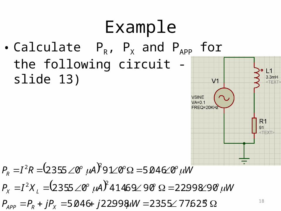
Example• Calculate PR, PX and PAPP for the following circuit - (see slide 13)
oXRAPP
oooLX
oooR
WjjPPP
WAXIP
WARIP
625.7755.23998.22046.5
90998.229069.41405.235
0046.509105.23522
22

19
Parallel RL Circuits
• Note that VS, IR and VR are all in phase
• IL is 90o out of phase with (lags) VS, IR and VR.
VS = VR1 = VR2 VS = VL1 = VL2 VT = VL= VR
IT =IR1+IR2 IT = j(IL1 + IL2) |IT|= sqrt(IR2 + IL
2)
RT = 1/[ (1/R1 )+(1/R2)] XT = 1/[(1/XL1 ) + (1/XL2 )] XT = 1/[(1/R ) + (1/jXL )]

20
Parallel RL Circuits• Branch Currents
– IL lags IR , VR and VS by 90º

21
Parallel RL Circuits
• Parallel Circuit Impedance– Impedance phase angle is positive since current phase
angle is negative
– Angles of ZT and IT have the same magnitude but opposite signs
• Calculating Parallel-Circuit Impedance (polar form)
T
ST I
VZ
22 RX
RXZ
L
LT
LITZ X
RT
1tan

22
Parallel RL Circuits
• Calculating Parallel-Circuit Impedance– rectangular form approach:
L
LT jXR
jXRZ
L
T
jXR
Z11
1

23
Parallel RL Circuits
• Parallel-Circuit Frequency Response
– The increase in frequency causes XL to increase– The increase in XL causes:
• IL to decrease• IT to increase• ZT to increase
– The decrease in IL causes IT to decrease

24
Example 1• Calculate the total current for circuit (a) in both rectangular and polar forms • Calculate total impedance of circuit (a)• Repeat for circuit (b)
oT
o
R
LI
LRT
T
LR
I
I
I
III
mAjI
mAImAI
T
04.1462.20
04.1420
5tantan
62.20425
520
5,20
11
22
kmA
V
I
VZ
mAI
VV
oo
o
T
ST
oT
oS
04.1429.004.1462.20
06
04.1462.20
06

25
Example 2 (Rectangular)• Calculate the total impedance for circuit (a) in both rectangular and polar forms • Calculate total current of circuit (a)• Repeat for circuit (b)
mAZ
VI
Z
jj
j
j
j
j
j
j
jXR
jXRZ
XR
oo
o
T
ST
oT
L
LT
L
04.1462.2004.1404.291
06
04.1404.291
59.7035.2821530000
108000000432000000
1200300
1200300
1200300
360000
1200300
360000
1200,300
26
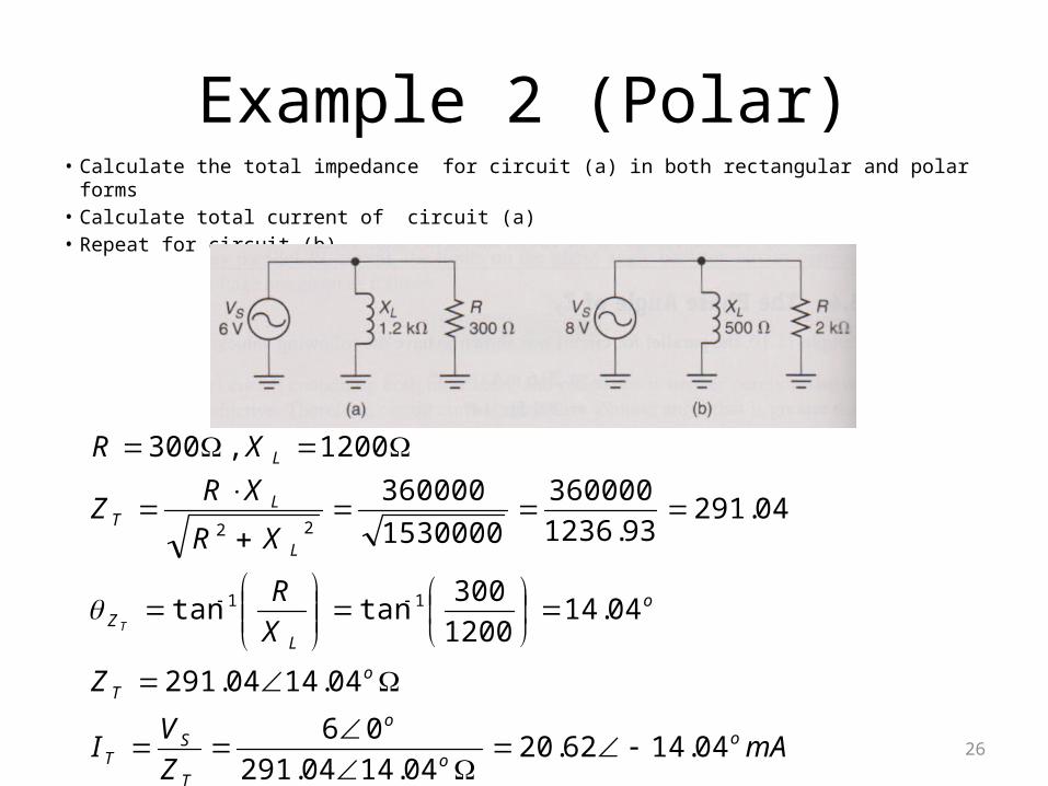
Example 2 (Polar)• Calculate the total impedance for circuit (a) in both rectangular and polar forms • Calculate total current of circuit (a)• Repeat for circuit (b)
mAZ
VI
Z
X
R
XR
XRZ
XR
oo
o
T
ST
oT
o
LZ
L
LT
L
T
04.1462.2004.1404.291
06
04.1404.291
04.141200
300tantan
04.29193.1236
360000
1530000
360000
1200,300
11
22

27

28
Series –Parallel RL Circuits
• First collapse the parallel RL portion into a single impedance ZP
• If this single impedance is in polar form, convert it to rectangular form
• Add any resistances/ reactances in series with ZP to get ZT.
– Remember you cannot add complex numbers in their polar form.
• Always assume that IT is the zero Phase reference!! And that VS and ZT have the same phase i.e. Same assumption as for series RL circuit

29
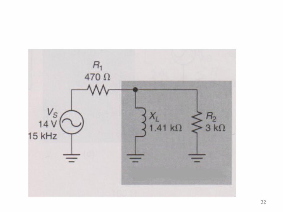
Example• Calculate the Equivalent Impedance, the total current and the current in each branch of the
parallel RL circuit shown below
oP
o
LZ
L
LP
kZ
k
k
X
R
kkk
kk
RX
RXZ
P
8.6428.1
8.6441.1
3tantan
28.1341.1
341.1
121
2222
2
2
oP kZ 8.6428.1
oT
ST
S
ooS
osP
kZ
jZZ
jZ
jkZ
kZZ
8.4854.1
11581015470
1158545
8.64sin8.64cos28.1
8.6428.1
Now convert to rect and back to polar
os kZ 8.6428.1
oT kZ 8.4854.1

30
Example Cont’d
• Knowing that
• Remember in a series circuit, IT is the phase reference and VS and ZT always have the same phase!!!
oT kZ 8.4854.1
oo
o
T
SRCT mA
Z
VI 009.9
8.481540
8.4814
oooTR VmAIRV 0273.4009.9047011

31
Example Cont’d
• Alternatively using a current divider equation
• Does IT = IL + IR2?
oo
oP
R
oo
o
L
PL
oooTPP
mAR
VI
mAX
VI
mAkIZV
8.6488.303000
8.6464.11
2.2523.8901410
8.6464.11
8.6464.11009.98.6428.1
22
oo
ooP
TR
oo
oo
L
PTL
mAk
mAR
ZII
mAk
mAX
ZII
8.6488.303000
8.6428.1009.9
2.2523.8901410
8.6428.1009.9
22
32

33
Remember!!
• For Series RL Circuits– IT and VR are the 0o phase reference
– VS and ZT have the same phase
• For Parallel RL Circuits– VS is the 0o phase reference
– IT and ZT have the same phase magnitude but opposite signs
• For Series-Parallel RL Circuits– Use same rules as Series RL Circuits