resistance of steel- and wood-pole foundations to
TRANSCRIPT
/.,,. Resistance of Steel- and Wood-Pole
Foundations to Uplifting and Overturning Forces
Research Report No. 28
by H. T. Hurst and J.P. H. Mason, Jr.
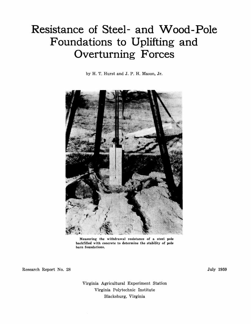
Measuring the withdrawal resistance of a steel pole backfilled with concrete to determine the stability of pole barn foundations.
Virginia Agricultural Experiment Station Virginia Polytechnic Institute
Blacksburg, Virginia
July 1959

ACKNOWLEDGMENT
This investigation of pole foundations was par-tially supported by the Inland Steel Products Company of Milwaukee, Wisconsin. This sup-port and the cooperation rendered by the company is gratefully acknowledged.
Invaluable assistance was generously given by B. R. Brasher, soil scientist of the U. S. Depart-ment of Agriculture; J. H. Hunter, professor of civil engineering, Clemson College; Augustine Perucci, of the Naval Bureau of Aeronautics, who rendered essential technical assistance in the de-sign of the versatile loading systems from sur-plus aircraft parts ; and the following VPI per-sonnel: J. R. Land, Jr., professor of civil engi-neering; Prof. J. E. Moody, soil scientist; Mrs. Fannie Reynolds, laboratory technician; and Dr. C. Y. Kramer, professor of statistics.

TABLE OF CONTENTS
Page
Introduction 5
Procedure ------------------------------- 5 Foundation Treatments --------------- 5 Evaluation of Soil Properties _________ 5 Loading Procedure, Overturning ______ 9 Loading Procedure, Uplifting __________ 10
Results ____ _ __ ______ __ _ _____ _ ___ ____ _ ___ 11
Discussion of Results --------------------- 14 Steel Poles, Overturning ______________ 14
Steel Poles, Uplifting ----------------- 15 Wood Poles, Overturning _____________ 15
Wood Poles, Uplifting ---------------- 15
Summary ------------------------------- 16
References ------------------------------ 16

LIST OF TABLES Number Page
1 Foundation Treatments ----------------------------------- 5 2 Soil Properties, Groseclose Silt Loam ----------------------·- 7 3 Steel Pole Overturning Data ------------------------------- 9 4 \Vood Pole Overturning Data ------------------------------ 9 5 Steel Pole Uplifting Data --------------------------------- 10 6 \Vood Pole Uplifting Data -------------------------------- 10
LIST OF FIGUHES Number Page
1 Basic Pole _ ___ _ _ _ ___ __ _ ___ _ _ _ __ _ ___ ___ _ __ __ _ ___ _ _ _ _ ______ 6
2 Basic Pole with Bearing Plates ------------------"'"~-------- 6 3 Basic Pole with (a) Concrete and Bearing Plates,
and (b) with Concrete --------,------------------------ 6 4 The Overturning Rig -------,..-------------~-------------- 6 5 Equipment Used for Digging Holes ------·----------------- 6 6 Soil Profile, Groseclose Silt Loam ------------------------- 7 7 Compaction Curve, Groseclose Silt Loam -----'------------- 8 8 Standard Proctor Compaction Test Equipment_______________ 8 9 "Large Proctor" Compaction Test Equipment ~----.c:_________ 8
10 Steel Pole with Bearing Plates being Extracted _____________ 11 11 Steel Pole in Concrete being Extracted _ _ _ _ _ _ _ _ _ _ _ _ _ _ _ _ _ _ _ _ 11
12-16 Lateral Movement of Pole at Surface ____________________ 11-12
17-20 Vertical Movement of Pole ------------------------------- 13 21-22 Overturned Poles from Different Treatments _______________ 14
Resistance of Steel- and Wood-Pole Foundations to Uplifting and Overturning Forces H. T. Hurst, Associate Profe.c;sor of .4gr'iculturnl Engineering
J. P. H. Mason, Jr., Assistant Professor of Agricultural Engineering
INTRODUCTION The evaluation of pole foundations for farm
buildings is but one of several coordinated stud-ies in balanced structural design of farm build-ings now under way at the Virginia Agricultural Experiment Station, Virginia Polytechnic Insti-tute. General evaluation of foundations for struc-tures is extremely difficult because (1) the strength qualities of soils vary widely and are greatly influenced by such factors as compaction and moisture content and (2) the accurate meas-urement of foundation stresses, foundation move-ments, and soil pressures is difficult even with controlled foundation loads. In view of these dif-ficulties in foundation research, the first objec-tive of this study was to evaluate the overturn-ing and uplifting stability of various wood- and steel-pole foundations for one specific soil, Grose-close silt loam.
Very specific procedures were followed in this study with the hope that the work could be co-ordinated with past and future research of this nature and that eventually all major soil classi-fications and conditions could be evaluated for pole foundations. Therefore, the second objec-tive of this study was to establish a procedure by which the stability of pole foundations could be evaluated for any soil through the use of stand-ard laboratory procedures.
PROCEDURE Foundation Treatments
On the basis of previous research, practical ex-perience, and general observation, it was decided that a considerable variety of pole-foundation treatments should be investigated. Tests were conducted with three replications of each of the treatments shown in Table 1, this page. The treatments were randomly located over a well-drained area (Fig. 4, page 6).
The 20-inch diameters of the holes were arbi-trarily selected after counseling with other engi-neers and soil scientists. A smaller hole would be more difficult to dig to depths of 51/2 feet in many soils, and uniform compaction would prob-ably be much more difficult to accomplish. The magnitude of this problem of pole foundations is such that it is very desirable to conduct investi-gations in a way that they can be correlated with other research. The USDA has investigated to some extent pole foundations in which 20-inch holes were used. On the other hand, Mahoney
(5)
Table 1.-Foundation treatments ---------- - -- ---- ____ , Foundation Depth Compacted Backfill in 20" Diameter Holes
Steel* Poles
(Fig. I, Page Ii)
Wood
41 9"
No. 7 Crushed Limestone
Soil
Soil with hearing plates, one top and cne bct-tom (Fig. 2, Page Ii)
One foot of concrete poured armmd base of pole, then soil and two hearing plates 12 inches below ground level (Fig. !la, page Ii)
Concrete, ground level to 6 inehes below bot-tom of pole (Fig. !lh, page Ii)
Soil !J' ()" --------------------
No. 7 crushed limestone
Poles, Soil Pressure 4' Ii" --------------------Treated No. 7 crushed limestone
Soil .5' ()"
No. 7 crushed limestone _, _____ _
""The quality of Rteel h; represented by the following results from yield tests on each pole: yield strength, 40,800 to 43,850 psi: ultimate i-~trength. f>2,XOO to fifi,200 psi.
and Nelson (3) * of Oklahoma, who have stud-ied pole foundation to a much greater extent, used 12-inch diameter holes. Evaluation of Soil Properties
One very important factor in pole foundations is the density of the soil, both undisturbed and compacted around the poles. Some important properties of the test soil are shown in Table 2, page 7. The compaction curve, Fig. 7, page 8, was determined by the standard Proctor com-paction tests described by Taylor (9) as follows:
In the test the soil is compacted in a cyl-inder with a diameter of 4 inches and a vol-ume of 1/30 cu. ft. The compaction is ac-complished by tamping the soil in three lay-ers of about equal thickness, each layer in turn being subjected to 25 blows by a 51/~-lb. hammer 2 inches in diameter at the striking surface, each blow having a free fall of 12 inches.
The dry unit weight or bulk density of the soil material can be easily calculated from the oven
•NumberH in 1mrentheses refer to appended refet·enceR.

VE L
5 7"
Figure 1.-Basic pole.
57 11
1_ -
Figure 2.-Basic pole with bearing plates.
(6)
GROU ND LEVEL
:t.t!f :t!/;. ·-:· .. ,,. ~ :. 1, ~".
5 7•
lj_, -20·~ (B)
Figure 3.-(a) Basic pole with concrete and bearing plates; (b) basic pole with concrete.
Figure 4.-The overturning rig. A maximum of six poles could be overturned at a time. Note that many of the poles or their foundations have failed.
Figure 5.-Equipment used for digging 20-inch holes 5% feet deep. Note the improvised extension blades, mak-ing possible the digging of 20-inch holes with a 12-inch, tractor-mounted auger. The improvised blades were fabricated by welding extensions to regular auger blades. The maximum depth possible with the auger was 4 feet; additional depth was obtained by loosening the soil with the straight spade (center) and removing it with the "spoon" (right).

dry weight of a known volume of that soil mate-rial.
Table 2.-Soil properties, Groseclose silt loam
Atterburg Limits Shear Strength
Composite Samples Composite Samples
Liquid Limit ... 7(i.O Test No. Stress, psf Plastic Limit ..... 5:l. 7 1 (i989 Plastic Index . .. 22. :1 2 751!i
Horizon
Ap B, B2 Ba c, C2
Depth, Inches
0-6 (i-10
10-28 28-:l5 :l5-41 41+
:1 (i785
Average 7097
Bulk Density, lbs/cu. ft. Moist11re <:ontent------------
% Dry Weight Composite -------- Samples
Field Field Mois- l 'ndis-
Capac- ture turbed ity* Content Soil
21.4 15.4 94.22 21.:1 Hi.4 94.22 41.6 :14.9 7(i. 1 :l 4:l. (i :l8.5 75.50 :rn. :i 24.4 80 .. 50 50.7 40.2 (i7.:rn
Com- Standard pacti<'n Proctor Around Com-
Poles paction
71.4 8(i to to
7(i.4 91
*Field Capacity-the percent moisture, dry weight basis, of a soil which has reached equilibrium with ~1 atmosphere of pressure.
In order to measure and control the degree of soil compaction in the 20-inch holes in which wood and steel poles were to be embedded, the following "large Proctor" test (Fig. 9, page 8) was developed:
The soil was compacted in a cylinder with a diameter of 20 inches and a volume of 4.0 cu. ft. minus the volume of the pole centered in the cylinder. The compaction was accomplished by tamping the soil in 4 layers of about equal thick-ness, each layer in turn being subjected to 50 blows by a 20-pound hammer 21/2 inches in diam-eter at the striking surface, each blow having a free fall of 24 inches. The dry-unit weight was then calculated as before; and the degree of soil compaction, about 83% of that produced with the standard Proctor test, was expressed in terms of the standard test. (See Table 2 and Fig. 6, this page, and Fig. 7, page 8, for more detailed soil information.)
The tamping procedure used in the large Proc-tor was also used for compacting soil and crush-ed stone for all poles. A constant volume of loose soil or crushed stone was used for compacting soil layers of 51/2 to 6 inches in the large Proctor cylinder; however, this procedure resulted in lay-ers of less uniform thickness in the holes due to irregularities of wood poles and the shape of the holes. The smallest fraction of a layer used was one half, since it was undesirable to attempt uni-
" Silt loam
29"
66"
31"
Very fine granular structure
Silty clay or clay Well-developed blocky structure (very hard digging)
Partially weathered shale (hard digging)
Figure 6.-Soil profile, Groseclose silt loam.
(7)

96
Dry Unit Weight = Wet Unit Weight 1 + Water Content
92
.µ
$ ·ri
~ .µ 88 ·ri § >i ~ Q
84
• I •
20
• •
I •
24 28
• •
32 36
• 40
Water Content, Percentage Figure 7.-Compaction curve, Groseclose silt loam.
Figure 8.-Staudard Proctor compaction test equip-ment. The maximum compaction resulting from these tests on this soil was 91.0 lbs/cu. ft. at a water con-tent of 26.2 o/o dry basis.
(8)
Figure 9.-The "large Proctor" test which was develop-ed for measuring and controlling soil compaction around the poles in terms of the standard Proctor test. Soil compaction resulting from the use of this equipment was approximately 83% of that produced by the standard Proctor test at water contents of 21 % -28% .

form compaction of soil in a 20-inch hole with less than 25 blows. Layers were slightly thinner for the steel poles than for the wood because of the difference in volume of the two poles, but no significant difference in compaction was detect-ed. Bulk density of the No. 7 crushed limestone was 84.3 lbs/cu. ft. loose and 95.6 lbs/cu. ft. com-pacted. Loading Procedure, Overturning
minute cycles (3 minutes loaded and 3 minutes unloaded) by a power-driven hydraulic system which supplied equal pressure to all cylinders em-ployed for any one pull. Using 1 cylinder for each pole, any number of poles up to 6 could be overturned at one time. A modified water-level recorder, attached to the pole at ground level, provided a continuous record of lateral movement at that point.
The overturning load for each pole was applied horizontally 7 feet above ground level (Fig. 4, page 6). Each load was applied in three 6-
Because each bay is supported by two poles, the overturning loading schedule in Tables 3 and 4 represents half the actual load exerted on a 16-ft. bay 14 ft. high. To establish a reference,
Table 3.-Steel pole overturning data --------------------------
Pole Loading, lbs. Percent Moisture -------------------------
1120 1680 2240 2800 :i:l6o Pole Days When When ---- ---- ---- ---- -----
Treatment Number Embedded Tamped Overturned Pole Movement, inches ---- ---- ---- ---- ---- ---- ----
15A 8 26.9 22.4 Missed I. :!6 Earth 24A 9 22.8 24.6 0.44 0.96 1.59
No. 7 Crushed
Stone
Earth, Plate top
and bottom
:JOA 9
l:lA 19A 26A
:lA 29A :l2A
14 21 11
10 11
22.4
20.8 25.4 2:l.5
25.4 0.67 1.20
o.:rn o.56 0.4 0.64
Missed
25.7 o.:i2 0 .. 64 26.4 0.26 0.58 25.6 0.24 0.62
2.00
0.91 1.00 1.22
I. 16 1.00 I. 12
1.32 1.32
I. 76
1.67
Number I.ayers
9Yz
Height of
Top I.ayer
9Yz S. High 9 Even
8Yz 9
10
llYz 10Yz 10
Even S. High Even
S.Low Even Even
---------------------------------------------------------------Concrete,
Earth, 2 Plates
Concrete
Treatment -----
Pole Pole Depth No.
4A :1' 6" 5A
14A
6A 20A 22A
8A 9A
llA
* Pole Size (in.)
----6.99 7.25 7.02
14 ](j 16
12 22 ](j
Days Embedded ----
25 2:l 24
25.6 2:1.8 22.7
25.2 0. 15 o.:l5 :l:l. 8 o. 18 0.28 23.4 0.16 o.:io
Missed 0.02 0.04 0.01 0.02
0.60 0.58 0.62
0.04 0.07 0.04
0.88 1.04
Missed 0.09 0.07
Table 4.-Wood pole overturning data
Pole J,oading, lbs.
0.08 0. 14
Percent Moisture -------------------------
When When Tamped Overturned
20.2 21.2 2:l.2
27.9 27.6 25.0
1120
I. 72 1.64 1.44
1680 2240 2800
Pole Movement, inches
:i. 28 2.64 2.CO
:1360
8Yz 8 8
Number I.ayers
S. Low S.Low
Even Even Even
Height of
Top Layer
Even Even
------------------------------------------------------------...=: 2:lA 6.58 2:l 22.2 27.8 1.28 2.24 :l.44 8Yz Even +.> 41 6" 7A 7.09 2:3 26.2 28.7 0.80 2.~o :i.:12 8>-:! Even ... " ;:.:: 27A 7. 12 2:1 24.(i 27.2 1.25 I. 92 :1.<JO :l.88 7Yz
12A 7.36 24 2:l. I 29.4 o. (i(i 1.20 1.98 2.64 :1. 12 9 5' 611 17A ll. 80 21 22.2 28. :i Missed 2.00 9Yz S. Low
21A 7.24 25 22. I 27.4 I. 24 I. 9(i :l.00 9Yz Even
2A 7.51 2:1 1.16 I. 74 2.60 7 Even ~J' {)" 16A 6.80 18 Missed 2.60 liYz S. High
3:lA 7.:l3 18 Missed 5Yz Even ~ -------------------------------------------------------------., ...=: "' " ... u
4' 6" IA
25A 31A
7 .18 7.02 7.66
30 20 21
0.58 0.56 0.55
0.88 0.99 1.00
1. :!6 1.48 1.52
1.80 1.84 1.84
2.52 9 7 7
S. High S. I.ow S.Low
~ -------------------------------------------------------------o lOA Z 51 6" 18A
28A
6.98 7.57 7.44
2:l 29 21
*Average diameters at ground level, bottom, and midway between.
0.56 0.37 o.:19
(9)
0.92 0.59 0.65
0.96 1.05
l .:!O 1.64
1.80 9 9 9
High Even S .High

the design load of 15 lbs/sq. ft. as specified by the Uniform Building Code was selected. Thus, the overturning force for a single pole at the de-sign load and for the building dimensions given was 1680 pounds. The loading schedule was be-gun at two-thirds design load and was increased by increments of one-third design load until fail-ure was reached. Loading Procedure, Uplifting
The uplifting force was supplied by a hand-pump hydraulic system with a cylinder supported directly over the pole by a heavy steel tripod.
The poles were extracted at the approximate rate of 2 inches per minute (Fig. 10, page 11). The vertical movement of each pole was measured by mounting a scale on the pole and reading the slippage with a surveyor's level as the uplifting loads were applied.
The uplifting loading schedule (Tables 5 and 6) started at 670 lbs/pole and was increased in increments of 970 pounds until a force of 4550 pounds was being applied or until the required forces to withdraw the pole 2, 4, and 6 inches were reached.
Table 5.-Steel pole uplifting data
Pole Lnuling, lbs. Days Percent Moist1!re -------------------------Em- ---------- li70 lli40 'WlO !l.580 4550
Pole becld- When When ---- ---- ---- ---- ----Treatment No. ed- Tamped Pulled Pole Movement, inches
Earth 15 24 !lO
No. 7 Crushed B4 Stone B5
Earth, Plate top
and bottom
Concrete, Earth
2 Plates
Concrete
B6
A3 A4 B2
A2 Bl B3
4 4 5
!l !l 5
5 5 5
12 l!l 12
19 18 14
20.75 21.8 2!1.1
24.0 22.0 2!l.4
25. !l 27.l 28.0
21.0 to
27.0
21.0 to
27.0
21.0 to
27.0
21.0 to
27.0
21.0 to
27.0
0 0 0
0 0 0
0 () ()
0 () ()
0 0 ()
0 0 0
()
0.0!1 0
0 0 0
0 0 0
0 0 0
0.05 0
O.O!l
O.O!i (). ]!) 0. 12
0 0 ()
0 0 0
0 0 ()
0.15 O.Oli 0.12
0. 12 0.!17 0.25
O.Oli 0 0
() 0 0
()
0 0
0.+8 0.20 0.!11
0.19 0.51i 0.44
0.19 0. 14 0.12
O.OU 0
(}. O(i
0 0 0
!' .. le Moved
2" 4" 6"
Load Heqnired, lbs.
!i!l60 li!J70 71!15
112!l2 7992 9!}!J(i
8750 8!l60 8245
1](i]0 12980 12750
!l2400 21050
6150 li470 71!'0
7!l44 777(i 58!l2
9280 8850 8770
10250 14!!10 l!l!lOO
15120
5710 li700 57'!4
4!120 4158 49C8
9820 8740 8550
81i50 15:rno 12250
14(i00 ll!l50
- ---··-----·---
Table 6.-Wood pole uplifting data ----------------· ----· .. -------------·
Treatment * Pole J,oading, lbs.
Percent Moisture----------- ---------Days -------- li70 l!i40 21il0 !!580 4.550
Embed- When When --- ---- --- ---
Pole Moved
2" 4" ()" Pole
Depth Pole No.
Pole Size (in.) ded Tamped l'nllecl Pole :'\fovement, inches Lmul Hequired, lbs.
Earth
No. 7 Crushed Stone
!l' 6"
4' 6"
5' ()"
~>' ()"
4' 6"
5' 6"
4 5
14
12 17 21
2 1li !l!l
1 25 !ll
10 18 28
7.78 7.82 7.41
7 .!l2 7.98 7.!Jli
7.89 7.79 7 .!15
7.55 7.79 8.05
7 .18 7.64 7.75
7.95 7.45 7.li6
2 2 Ii
2 1 5
!l 2 1
5 5
2 4 5
2 2 4
21. 2 21.2 22.li
2!1. !l 21.4 24.2
24.4 2:1.:1 28.5
21.0 to
27.0
21.0 to
27.0
21.0 to
27.0
21.0 to
27.0
21.0 to
27.0
21.0 to
27.0
*Average diameters at ground level. bottom, and midway between.
(10)
0 0 0
0 ()
0
0 0 ()
0 0 0
() 0 0
() 0 0
O.O!i 0.75 O.O!l
O.Oli O.Oli
0
0.(Hi 0 0
o.:rn O.Oli O.Oti
0.19 ()
0.0li
0.05 ()
o. l!l
0.44
]. 12
0.75 1.25 0.28
(),(Hi
0 0.04
1.50 0.!!8 0.25
0.88 0.!!5 0. ]!)
0.20 O.O<i 0.1:1
1. 75
0.19 0.20 o.::o
0. 7,5 0.5!1
1.'25 O.li2 0.(i2
0.!!5 0.12 0.20
1.51i
l. 2.5 1.00
1. 20 l .!17
!Hi20 1890 2908
2895 25!)0 :l400
4550 4540 !1400
2!!80 iil80 5140
!14.50 51i10 501i0
0. (i() li800 o. 25 8405 0. !HI 1 I '220
!i885 1995 2700
2780 221i5 !l!l48
44!l0 4!J(i0 2700
17!'.0 :l885 !l7fl.5
4210 !i!W5 5()10
4050 2050 2592
21i40 2lli0 !l!l48
4100 52!l5 2!!80
1025 '25!!0 4!1!;()
4150 56'20 4750
901i0 10152 78!l0 10800 8!!00 84'20

Figure 10.-A steel pole with one top and one bot-tom bearing plate being extracted. The minimum load required to extract one of these poles 2 inches was 8245 lbs., or more than 9 times design load.
Figure 11.-A steel pole in solid concrete being ex-tracted. The minimum load required to extract one of these poles 2 inches was 21,050 lbs., or more than 23 times design load.
(11)
The uplifting loads were not based on any par-ticular design; but using the uplift load of 9 lbs/ sq. ft. as given in the Uniform Building Code, the loads were spread over a range of forces which would accommodate lightweight buildings with 24- to 40 ft. spans and bay lengths up to 24 ft. A load of 2 lbs/ sq. ft. was used as the ap-proximate dead weight for the roof and walls.
RESULTS Tables 3-6 and Figures 12-22, pages 9-14, give
the experimental results.
Ill IJJ
:c 0 z
. t-z LL.I
:E IJJ
> 0
:E
2
0
4 _
3
2
0 -
LATERAL MOVEMENT OF POLE AT SURFACE
10 LB.ISO. FT,,
STEEL POLES
4' 9"
WOOD POLES
0 o o am am []]IJ DEPTH 3.5' 4.5 ' 5.5' 3.5' 4.5' 5.5' 0 EARTH ~ TOP BEARING PLATES & ITIIl CRUSHED STONE I' CONCRETE, BOTTOM l?Z3 CONCRETE ~ ONE BEARING PLATE,
TOP 8 BOTTOM
Figure 12.

(/)
w :I:
u z
. 1-z w
2
4
3
2
D DEPTH:
D DEPTH 3.5'
Cf)
w :I:
u z
. 1-z w :E w > 0
:I
2
4
2
D DEPTH:
w 0:: ::) ....J <(
LATEHAL MOVEMENT OF POLE AT SUHFACE
2
STEEL POLES
ALL
WOOD POLES
Cf)
LL.I
::c u z
. ... z LL.I
2 LL.I
> 0 2
w a: ::) ....J
STEEL POLES
0..L-~~<(----..UL------~----...... ----~·~ ~
4 .
3
2
CJ DEPTH:
am ~ ALL POLES
~ 4' 9"
WOOD POLES
w w w a: a: a: :J ::) :J ...J ...J ....J
0.L--~------~----....... ~-----~-------.... ------CJ 4.5'
CJ 5.5'
am 3.5'
[ill 4.5'
Figure t:l.-15 lbs/sq. ft.
STEEL POLES
rrrn ~ ALL POLES 4' 9"
WOOD POLES
CJ DEPTH 3.5'
CJ 4.5'
CJ 5.5'
am 3,5'
[ill 4.5'
Cf)
w ::c u z
. 1-z w :E w > 0
~
Fi!!'ure 15.-25 lbs/sq. ft.
2 STEEL POLES
w w w a: a: a: :J :J :J ...J ....J ...J <( <( <(
0.1-~-----IL-------~------~~~--~~ ~
4
2
CJ DEPTH:
am &"SS ALL POLES
w w a: 0:: :J :J ....J ....J <( <l
4' 9"
WOOD POLES
w 0:: :J ...J
[ill 5.5'
o...__~ ____ .... ..._ __ _.. ...... __ __...._ ____ ..... .._ __ ..... _ <( ~ ~ ~
0.1...-----------------"""":-::----~--~== D DEPTH 3.5'
CJ 4.5'
CJ 5.5'
am 3.5'
am 4.5'
[ill 5.5'
CJ DEPTH 3.5'
CJ 4.5'
D 5.5'
am rrm rrm 3.5' 4,5' 5.5'
Figure 14.-20 lbs/sq. ft. Figure 16.-30 lbs/sq. ft. Legend
CJ EARTH ~ [II] CRUSHED STONE rzl CONCRETE ~
TOP BEARING PLATES t. I' CONCRETE, BOTTOM ONE BEARING PLATE, TOP 8 BOTTOM
(12)

VEHTICAL MOVEMENT OF POLE
2
STEEL POLES I/)
UJ
:c u z orrm~oo
DEPTH: ALL POLES 4'9"
~
z w ::E UJ 2 > 0
2
CJ DEPTH 3.5'
CJ 4.5'
WOOD POLES
CJ 5,5'
am 3.5'
rrrn 4.5'
Figure 17.-1640 lbs uplift per pole.
I/)
UJ
:c u z
~
z UJ
2 ILi
> 0 ::E
2
STEEL POLES
D ITITI ~ 00 DEPTH: ALL POLES 4•9··
WOOD POLES
rrm 5.5'
I/)
LLI
:c u z
~
z LIJ
::E
2
D DEPTH:
ILi 2 t-
> 0
::E
D DEPTH 3.5'
STEEL POLES
[lilJ ALL POLES 4' 9"
WOOD POLES + +
CJ 4.5'
CJ 5.5'
rrm 3.5'
[ill 4.5'
Figure 19.-3580 lbs uplift per pole.
I/)
LIJ
:c u z
~
z LIJ
::E LIJ
> 0
::E
2
2
STEEL POLES
orrm~oo DEPTH: ALL POLES 4'9"
WOOD POLES
+ + + +
OIIJ 5.5'
0..L&A&~---------------'Uo&·· CJ DEPTH 3.5'
CJ 4.5'
CJ 5.5'
am 3.5'
IIJ]J 4.5'
OIIJ 5.5' D
DEPTH 3.5' CJ 4.5'
CJ 5.5'
rrm 3.5'
[ill 4.5'
Fieure 18.-2610 lbs uplift per pole. Figure 20.-4fi50 lbs uplift per pole.
Legend
CJ EARTH 888 TOP BEARING PLATES S [I]] CRUSHED STONE I' CONCRETE, BOTTOM l!Zil CONCRETE &'S.'9 ONE BEARING PLATE,
TOP a BOT TOM
(13)
OIIJ 5.5'

Figure 21.-Front view of overturned poles having the following treatments: (left to right) bearing plates, one top and one bottom; crushed stone; concrete at bottom and two bearing plates at top; and earth.
Figure 22.-Side view of the above.
DISCUSSION OF RESULTS Since the required anchorage for a pole build-
ing depends on the wall and roof area supported by each pole, a building 24 ft. wide with an eave height of 14 ft. and a bay length of 16 ft. was se-lected for consideration. Design loads were con-sidered to be 15 lbs/sq. ft. for overturning and 9 lbs/sq. ft. for uplifting minus a dead load of 2 lbs/sq. ft.
The pole-anchorage treatments investigated in this study provide a wide range of resistance to uplifting and overturning forces acting on a build-ing. The building designer must decide how much vertical and horizontal movement of pole founda-tions can be tolerated. If some movement can be allowed at design load, a variety of backfill and pole-depth combinations, many of which are in common use today, will provide adequate pole-building foundations. If no movement is permit-ted, it appears that concrete to a depth of 4 to
(14)
5 ft. is the logical backfill to resist horizontal forces. Overturning forces were found to be more difficult to resist than uplifting forces for the · particular wall-roof-area ratio considered. There-fore, a variety of backfill and depth combinations could be used to minimize upward movement for the buildjng considered. However, a small wall area low in height combined with a large, rela-tively flat roof area would greatly change the re-lationship of uplifting and overturning forces. The building designer can utilize the data present-ed in Tables 3 through 6, pages 9-10, as relative indications for any particular situation.
As shown in Tables 3 through 6, the soil mois-ture content for tamping, extracting, and over-turning varied from about 20 to 28%, and the longest duration of embedment was 30 days. Only 1.87 inches of rain fell between the time of tamping the first pole and overturning the last. During this time the soil was never frozen, satu-rated, nor extremely dry.
Following is a summary of the statistical analy-sis made on the data collected. Each backfill treatment was replicated three times; but during loading, some loads and movements were missed. (See Tables 3 through 6, pages 9-10.) Steel Poles, Overturning
Analysis of variance showed highly significant differences between the backfill treatments of the steel poles with regard to the lateral pole movement. The means of the pole movements for each backfill treatment are ranked and their significance indicated as follows:
POLE MOVEMENT, inches (.Ol level)
Load, 111JO lb. Earth and
Concrete and Bearing Crushed Con<'rete two Plates Plates Stone Earth
0.0150 0.1633 o.~733 0.8800 0.5550
Load, 1680 lb. Earth and
Concrete and Bearing Crushed Concrete two Plates Plates Stone Earth
O.O~JOO 0.3100 0.6000 0.6133 1.0800
Load, 1J~40 lb. Earth and
Concrete and Bearing Crushed Concrete two Plates Plates Stone Earth
0.0.500 0.6000 1.0433 1.0933 1.6500
Note: Any two means not underscored ·by the same line are signif-icantly different.
From the above ranked means, it can be seen that at the three loads, the concrete backfill is significantly more resistant to overturning, while earth is the least resistant. It is interesting to

note that crushed stone is significantly better than earth at all load levels. Steel Poles, Uplifting
Analysis of variance again showed highly sig-nificant differences between the backfill treat-ments of the steel poles with regard to the verti-cal movement of the pole. The means of the pole movements for each backfill treatment are rank-ed and their significance indicated as follows:
POI.E MOVEMENT, inches (.01 level)
T.oad, 2610 lb.
Concrete
0
/.oad, 8580 lb.
Concrete
0
T.oad, 45.50 lb.
Earth and Concrete an<l Bearing
two Plates Plates
0 0
Earth and Concrete and Bearing
two Plates Plates
0 0.0200
Earth and Concrete and Bearing
Concrete two Plates Plates
0 0.0400 0.1500
Earth
0.02(i(l
Earth
0. 143:!
Earth
0.:1::00
Crushed Stone
o. 11:1s
Crushe<I Stone
0. 2183
Crushed Stone
0.!19117
From the above means, it can be seen that the concrete backfill did not allow the pole to move during any of the above loads. However, the ranked means show that the movement allowed by the backfill treatments of concrete, concrete and two plates, and earth and bearing plates was not significantly different at any of the above loads.
Uplift forces were continuously applied to the steel poles until movements of 2, 4, and 6 inches were reached. Analysis of variance of these re-quired loads showed highly significant differences between the backfill treatments. The means of the loads for each backfill treatment are ranked and their significance indicated as follows:
APPI.IED J,OAD, lbs. (.01 level)
2-inch Movement Earth and
Concrete aml Crushed Bearing Concrete two Plates Stone Plates Earth
28,083 12,447 9,720 8,4.~2 G,H22
4-inch Movement J<~arth and
Concrete and Bearing Crushed Concrete two Plates Plates Stone Earth
15, 120 12,620 8,967 G,984 4,938 --------
(15)
ll-i11clt Mol'ement Earth and
Conl'rete nnd llt>aring ConC'rete two Plates Plait's
l'l,975 12,077 !l,O'.l7
Earth
(i' (Jl.!i
Cruslu•d Stone
From the above ranked means, it can be seen that concrete is significantly better at the 2-inch movement but is not significantly better than the treatment consisting of concrete and two plates at the 4-inch and 6-inch movements. Con-sidering all the data for uplifting, it is interesting that the relative resistance of crushed stone and earth varies throughout the test.
Wood Poles, Overturning Analysis of variance with regard to the lateral
pole movement showed highly significant differ-ences between the two backfill treatments and between the three depths. The interaction was n:>t significant. The means of the pole move-ments for both backfill treatments at each of the 3 depths and for 2 loads are ranked and their significance indicated as follows:
POLE MOY EM ENT, inl"lll's (. 01 Jen!)
T.ood, 1120 lb.
Earth O.!liiOO 1. 1100 I .COOO
Crushed Stone 0.4400 O.!iGOO 1. lCOO
I.oat!, WW lb.
Enrth 1.5800 2. liiOO 2. 8~00
Crushed Stone 0.7200 O.!l/iCO 1. 7400
Because a highly significant difference was shown between the two backfill treatments, the above ranked means indicate the significance of the depth for a particular backfill. At the 1120-pound load, it is seen that there is no signifi-cant difference between the 51/:!-foot and the 41/~foot depths for either of the backfill treatments. However, at the design load of 1680 pounds, the pole resistance is significantly different for each depth as well as for each backfill. Wood Poles, Uplifting
Analysis of variance showed no significant dif-ferences between the two backfill treatments with regard to Yertical pole movements at the 1640-pound and 2610-pound loads. Pole depth was not significant and there was no interaction. This was probably because of greater variations with-
in treatments than between treatments at the relatively low loads.
As was done 'Nith steel poles, uplifting forces were continuously applied to the wood poles until 2-, 4-, and 6-inch movements were reached. Analy-sis of variance of these loads showed highly sig-nificant differences between the two backfill treatments and between the pole depths. Inter-action was not highly significant at the 4-inch and 6-inch movements. The means of the loads at each designated movement for both backfill treatments and for each depth are ranked and their significance indicated as follows:
APPLIED LOAD, lbs. (.OJ level)
~-inch ill 01,emc11l 5Y2 4)1 :lY2
Earth 4 rn:1 291l2 2806
-----·----Crushed Stone 8808 4707 42:1:1
----------
4-incli M 01•emc11t
Earth 40:!0 2798 28(i0
----------
Crushed Stone 8'.197 5'.195 :111:1
---------ll-inrh M 01•e111r11/ !) ~-~ 4.1.1 :1)-:i
Earth '.1905 271() 2897
---------Crushed Stone 9791 484-0 2648
The analysis of variance and the above ranked means show that crushed stone is significantly more resistant to uplifting forces than earth and that, in the case of each backfill, the 5%-ft. em-bedment depth is significantly better than the other depths tested. The interaction at the 4-inch and 6-inch movements indicate the increase of the difference of resistance between earth and crushed stone as the depth increases. For ex-ample, at the 4-inch movement, the differences are 253, 2597, and 4367 pounds for depths of 311~, 411~, and 51/:! feet, respectively. Therefore, the resistance of the crushed stone increases fast-er as the depth is increased than does the resist-ance of earth.
SUMMARY This study consisted of a series of uplifting
and overturning tests on (1) pressure-treated poles backfilled with (a) compacted soil or ( b) compacted crushed limestone at depths of 31/2, 41/:! and 5 ~~ feet, and ( 2) light-gage steel poles backfilled ~%; feet with (a) concrete, (b) one foot of _concI:~te around the bottom of the pole and cqnip?-cted soil above with two bearing plates o~e f *;lot/belo'Y the surface, ( c) compacted, soil with 'Li~ bearing plate at the bottom and. one a foot l)e1ow the ;Surface, (d) compacted· c'rushed limesfon~;- "itnd ( e) compacted soil.
', ·,, 1., ••
:/ ,.•·'.
(16)
Each treatment was replicated three times, both in uplifting and overturning; and the data were statistically analyzed. All tests were com-pleted within 30 days without any freezing and thawing or appreciable wetting and drying.
The following conclusions are based on the data obtained from this limited study on a single soil type - Groseclose silt loam - at a narrow range of moisture content: 1. Concrete backfill was the only treatment that
approached complete stability (no movement) of pole foundations at design loads.
2. Overturning was much more difficult to re sist than uplifting for the height, width, ar bay length considered. ,
3. Steel poles resisted overturning and ' ' ing better than did wood poles at a con. 1
ble depth. 4. Crushed stone resisted overturning sil , . '
cantly better than did earth. 5. There was essentially no difference in ·, "'
lifting resistance of earth and crushed sto1• '-at initial movement, but crushed stone was significantly more resistant with pole move-ments of 2 to 6 inches.
6. Maximum uplifting resistance was usually de-veloped with a pole movement of betwr· 2 and 6 inches.
7. The pole depth increases stability at a1 creasing rate.
1.
2.
3.
4.
5.
6.
7.
8.
9.
REFERENCES Hunter, J. H. "Engineering Soil Classif' tion for Residential Developments," Va. Poll Inst. Engr. Expt. Sta. Bui. 130, Feb. 1959. · Law, T. A. "Soil Resistance to Pole p,, .. ing," Agric. Engr. Senior Student Repv·t. unpublished, Va. Poly. Inst., Blacksburg, March 1959. Mahoney, G. W. A. and Nelson, G. L. "Pre-consolidated Anchorages for Pole-Type Struc-tures," Dept. of Agri. Engr., Oklahoma A&M College, Stillwater, 1958. Mason, J.P. H., Jr., and Hurst, H. T. "Equip-ment for Accelerating and Evaluating Simu-lated Natural Forces on Full-Scale Building Sections," Transactions of the ASAE, Vol. 1, No. 1, pp. 86-88, 96, 1958.
-
Nelson, G. L., Mahoney, G. W. A., and Fry-rear, J. I. "Stability of Poles Under Tilting Moments, Part I," Agric. Engr. Vol. 39, No. 3, pp. 166-170, March 1958. Nelson, G. L. "Stability of Poles Under Tilt-ing Moments, Part II," Agric. Engr. Vol. 39, No. 4, pp. 226-230, April 1958. Patterson, Donald, "How to Design Pole-Type Buildings," American Wood Preservers Insti-tute, 1957. Skinner, S. D., "Development of an Appara-tus to Pull Posts," Agri. Engr. Senior Stu-dent Report, unpublished, Va. Poly. Inst., Blacksburg, May 1957. Taylor, D. \V. Fundamentals of Soil Me-chanics, John Wiley, New York, 1948.