resistance and powering - İtÜ gemi İnşaatı ve...
TRANSCRIPT

RESISTANCE AND POWERING

There can be no absolute terms of optimum form for ships. The designer must make
many compromises. Even in terms of resistance one form may be better than another at
one speed but inferior at another speed. The shape of a ship hull is determined by many
competing influences.
For ease of construction, it should be a rectangular box;
for adequate transverse stability, it must be wide;
for adequate strength as a beam being bent in a longitudinal plane, it must be deep.
All these factors influence the shape of a hull, but often the primary factor is the dynamic
interaction of the hull with the water. The interactions that govern the resistance of the
hull to steady forward motion--a resistance that determines the choice of propulsive
power--usually demand the greatest attention from the naval architect. While the
minimization of resistance is a common design goal for all ship types, other
hydrodynamic performance characteristics such as seakeeping and manoeuvrability
performance may be more important for some ship types such as passenger vessels and
surface warships.
Until somewhat over a century ago, predicting the speed of a proposed ship was all
art and no science. Then, as steam engines replaced sails, half the difficulty was
removed: naval architects no longer had to guess what wind forces and directions
would be available to push the ship along. The other half of the difficulty lay in
predicting the resistance of any given hull form to being moved through the water
at any given speed. Naval architects still have no precise quantitative understanding of
that problem. Since the early 1870s, however, the insights of William Froude have
produced generally satisfactory ways to estimate resistance. These are usually based,
either directly or indirectly, on the use of model basins. Naval architects still have a
lot to learn about predicting the speed and power of boats and ships. Their
estimating methods are nearly all derived from empirical evidence, either from
model tests or from existing ships. Adding to the difficulty are hard-to-predict
influences such as sea conditions, loading conditions, and degree of fouling (for
example, barnacles) on the underwater hull.

Let’s start this discussion of the components of resistance by considering the
case of the deeply submerged submarine. Let us assume that the craft is well
shaped. That being the case, the only important source of resistance to forward
motion will be the friction caused by the viscosity of the water. The energy used
to force the water aside at the bow will be fully regained as it closes together at
the stern.
•Frictional resistance
•Wavemaking resistance or residual resistance
Components of Resistance

Friction: Contrary to popular opinion, a ship's frictional resistance is not so
much between hull and water as it is within the water itself. Let’s try to
explain.
As the hull slides through the water, a thin coat of the water will attach itself to
the the hull and move along at the ship' s speed. Owing to the water' s viscosity
(stickiness), this innermost layer will try to induce the second layer to come
along; but that same viscous property will cause the third layer to resist the
forward motion of the second layer. The cumulative result is that many layers
will be caught up and tend to follow the hull, but each will be less affected than
its interior neighbor. Eventually, as the effect gets smaller and smaller, it
disappears altogether at some finite distance from the hull. The body of water
that is dragged along is known as the boundary layer. Its thickness will be
influenced by the relative roughness of the hull surface and will gradually
increase from bow to stern. The accumulation of trailing water at the stern is
the wake. So, while we can reduce frictional resistance by keeping the hull
clean and smooth, we only fool ourselves by coating it with grease, a trick that
has been reinvented a thousand times but never with success.

Wave-making. If our submarine rises to the surface, a new source of
resistance will appear: wave-making. The force of the bow pushing against the
water will now produce waves. Since the waves must overcome gravity, they
will absorb energy. Of course there are other waves created, too, such as those
at the stern. We can generalize by saying that wave-making resistance arises
from variable pressures between hull and water surface working against gravity.
Another source of resistance closely related to wave-making is that of eddies
forming behind blunt appendages, shaft struts, rudders, and so forth. In a well-
designed vessel this source of resistance is not large and is usually lumped in
with wave-making. The wave- and eddy-making resistances are often referred
to collectively as residual resistance.

Effect of Speed, Size, Main Dimensions and Hull Form Parameters
on Resistance

Major components. Most ships and boats, then, have two major components
of resistance to forward motion: friction (overcoming viscosity) and residual
(largely wave-making, overcoming gravity).
Naval architects try to minimize frictional resistance by providing a smooth
hull and then trusting to the operators to maintain it in good condition. This
requires frequent cleaning and the application of high quality paints to resist
both fouling and corrosion.
Naval architects try to minimize residual resistance by developing good hull
forms.
In most merchant ships, the frictional resistance is perhaps three to four times
as large as the residual resistance. In relatively high-speed vessels (such as
passenger ships, naval combat craft, yachts, or ferryboats), the two resistances
might be about equal.
Except in a small minority of cases, air resistance is so small (perhaps only a
percent or two of total resistance) that naval architects feel safe in ignoring it
altogether.

Reducing wave resistance (Bulbous bow forms)
Central aim: Among a naval architect's most challenging responsibilities is that
of selecting an engine that will drive a proposed ship at the right speed. Once the
vessel is placed in service, failure to meet the owner's specified speed will cause
the designer acute embarrassment and penalty. On the other hand, if the vessel is
found capable of appreciably greater-than-specified speeds, the embarrassment
arises from having wasted the owner's money on an oversize engine. Hitting the
bull' s eye is no easy task.
Procedure. In selecting an engine the naval architect must go through a
multistep procedure culminating in an estimate of the required horsepower.
Brake horsepower (BHP) if a diesel or gasoline engine,
or shaft horsepower (SHP) if a steam turbine.
BHP and SHP are identical in a direct-connected diesel engine.
In geared engines BHP goes into the reduction gears; SHP comes out. The
difference, caused by friction within the gears, is usually less than 3 percent.
Explaining the procedure for estimating power is easier if we start with the
engine output (BHP or SHP) and work our way backward to see what happens
to that power and how it is finally dissipated.
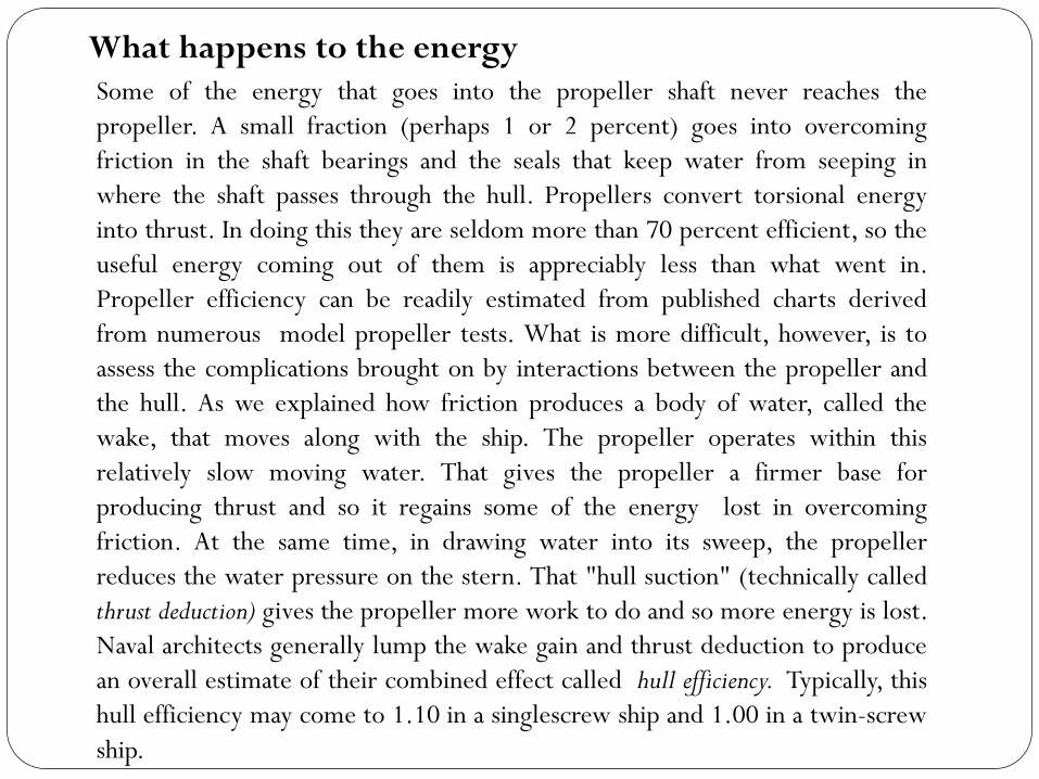
Some of the energy that goes into the propeller shaft never reaches the
propeller. A small fraction (perhaps 1 or 2 percent) goes into overcoming
friction in the shaft bearings and the seals that keep water from seeping in
where the shaft passes through the hull. Propellers convert torsional energy
into thrust. In doing this they are seldom more than 70 percent efficient, so the
useful energy coming out of them is appreciably less than what went in.
Propeller efficiency can be readily estimated from published charts derived
from numerous model propeller tests. What is more difficult, however, is to
assess the complications brought on by interactions between the propeller and
the hull. As we explained how friction produces a body of water, called the
wake, that moves along with the ship. The propeller operates within this
relatively slow moving water. That gives the propeller a firmer base for
producing thrust and so it regains some of the energy lost in overcoming
friction. At the same time, in drawing water into its sweep, the propeller
reduces the water pressure on the stern. That "hull suction" (technically called
thrust deduction) gives the propeller more work to do and so more energy is lost.
Naval architects generally lump the wake gain and thrust deduction to produce
an overall estimate of their combined effect called hull efficiency. Typically, this
hull efficiency may come to 1.10 in a singlescrew ship and 1.00 in a twin-screw
ship.
What happens to the energy

Effective horsepower
The product of propeller efficiency and hull efficiency is called the propulsive
coefficient. This is used to convert the power delivered to the propeller to the
power that would be required to pull the ship through the water if no propeller-
related complications were involved. This is sometimes called towrope horsepower
(THP), but more commonly effective horsepower (EHP). It can be estimated from
the three independent components of resistance already explained: friction,
wave-making and a small increment for appendages.
Numerous experiments have shown that frictional resistance will vary directly
with the ship' s wetted surface (which is the surface area of the underwater
hull), with the ship's speed raised to an exponent somewhat less than two and,
of course, the degree of roughness of the hull. Other factors are the ship' s
length and the viscosity of the water, which will vary slightly with temperature
and degree of salinity. Long ships have relatively less frictional resistance per
unit of area.
Estimating frictional resistance

The task of predicting wave-making resistance is considerably more difficult.
Naval architects simply do not understand in any quantitative way the physics of
how a ship creates waves. Strictly mathematical approaches to the analysis have
been under study for several decades, but most design methods in use today still
rely on empirical evidence from model basin work or derive their conclusions
from measured performances of existing similar ships. In some instances, model
basin researchers have tested large numbers of methodically related hull forms.
These are called standard series, and their results have been analyzed and
published so that naval architects can derive a good approximation to the wave-
making resistance per ton of displacement for any normally shaped hull form.
Once wave-making resistance has been estimated, wave-making horsepower can
be derived. The sum of the two horsepowers, plus a modest increment for
appendages, will produce the total effective horsepower.
Estimating wave-making resistance

Required engine powers are usually estimated by the following step-by-step
procedure:
1. Measure the proposed vessel' s wetted surface from the lines drawing and use
that to estimate frictional horsepower.
2. Estimate wave-making resistance and corresponding horsepower
requirements from published standard series results or from available data on
existing similar ships. If time and budget permit, the services of a commercial
model basin may be engaged not only to check estimates, but perhaps to refine
the hull form by testing variations on the original design.
3. To the sum of the frictional and wave-making horsepowers add an increment
for appendages that were not fitted to the model. This may amount to about 7
percent for a single-screw ship with a rudder as the only appendage. In a well-
designed twin-screw ship it may come to 12 percent.
4. The sum of the powers found in the first three steps will be the estimated
effective horsepower, EHP. Dividing that figure by the propulsive coefficient
leads to the horsepower that must be delivered to the propeller. The naval
architect then adds a few more percentage points for shaft losses to arrive at
SHP. Another small increment will provide BHP.
Estimating required engine power

5.Having carefully developed estimates of SHP or BHP (often to four significant
figures), the naval architect must now add a prudently generous margin in
recognition of real-life conditions the ship will have to face. To this point all
calculations have been based on an idealized set of assumptions: perfectly
smooth hull, fair weather, and smooth seas. The usual margin for service
conditions is a rather arbitrary 15 to 25 percent. Another margin may be
appended if the type of engine is such that its output may be expected to
diminish over the years. I think you may now see why this procedure for
arriving at the necessary horsepower should be called an estimate and not a
calculation .
6.With the above-derived estimate of required power, the naval architect is
ready to select a standard engine or turbine, usually right out of some
manufacturer's catalog. Since off-the-shelf units will seldom provide the exact
power required, prudence dictates going for a standard model of slightly more
power than the estimate.

Engine Reduction
Gear Bearing Seals
Screw Strut
BHP SHP DHP
THP
Shaft
Ship Train Drive

Brake Horse Power (BHP)
• Power output at the shaft coming out of the engine before the reduction gears
Shaft Horse Power (SHP)
• Power output after the reduction gears (at shaft)
• SHP=BHP - losses in reduction gear
Delivered Horse Power (DHP)
• Power delivered to the propeller
• DHP=SHP – losses in shafting, shaft bearings and seals
Thrust Horse Power (THP)
• Power created by the screw/propeller (i.e. Propeller thrust)
• THP=DHP – Propeller losses

E/G R/G BHP SHP
Shaft Bearing
Prop. DHP THP EHP
Hull
Relative Magnitudes?
BHP>SHP>DHP>THP
EHP is approximately equal to THP (usually slightly less)

Screw propeller
Nozzle propeller

Froude's insight. Before Froude's basic work, starting in 1868, various
engineers (including Benjamin Franklin) had tried to predict ship speed based
on model tests. They had all failed, however, because they did not understand
how to extrapolate the model results to the full-size ship. Froude realized that
the difficulty lay in the fact that the two major components of resistance
(friction and wavemaking) followed different physical laws in scaling up from
model to ship. One of his unique contributions, then, was to treat friction and
wave-making separately in going from model results to full-scale prediction.
Froude understood the laws of similitude. These tell us how physical
characteristics are affected by scale.
Model Basin Theory

Froude observed that when ship and model were both moved at the same
Froude number both produced identical (to scale) wave profiles. That is, if the
model showed a wave crest at the bow and another at the stern, the ship' s wave
profile would show exactly the same pattern. From this he reasoned, correctly,
that ship and model wave-making resistances would vary directly as their
displacements when both were moved at the same Froude number. As for
frictional resistance, simple towing tests on a series of flat planks (essentially no
wave-making) showed him that the viscous resistance varied directly with the
wetted area and with the speed raised to a power somewhat less than two.
Froude's number:

Froude's technique. Armed with the concepts spelled out above, Froude
was ready to use his model basin. He had built an exact scale model of some
ship. He then towed it through the water of his tank at the Froude number
corresponding to the ship' s design speed, and measured the pounds of pull
required to maintain that model speed. This gave him the model's total
resistance. He then calculated how much of that total was contributed by
frictional resistance. Subtracting that from the total resistance gave him the
(wave-making plus eddy) resistance. And now you know why the cumulative
wave and eddy component is called residual resistance. Now Froude was ready to
use his model to predict the full-scale ship's resistance (and from that, EHP).
First, the ship's frictional resistance was predicted using much the same
formulation as that used for the model, with a correction for relative roughness.

Second, the ship's residual resistance was taken as the model's residual
resistance multiplied by the ratio of their displacements (with, of course, ship
and model speeds both at the same Froude number). As you will notice, he kept
in mind that the scaling laws differed between frictional and residual
resistances. Finally, he added together the two individually arrived-at resistances
so as to provide a reliable prediction of total full scale resistance, and from it
EHP. The diagram in the following figure illustrates Froude's logic and may
help clarify the thinking outlined above. Today, more than a century later, naval
architects still exploit Froude's method. Numerous improvements have of
course been developed, but the fundamental approach is still the same. Until
hydrodynamicists can completely solve the basic physical laws of wave-making
and the complex flow around the hull, naval architects will continue to rely on
Mr. Froude's model basin techniques.


0
200
400
600
800
1000
Eff
ec
tiv
e H
ors
ep
ow
er,
EH
P (
HP
)
0 2 4 6 8 10 12 14 16
Ship Speed, Vs (Knots)
POWER CURVEYARD PATROL CRAFT

The figure shows the 360-ft-long model basin at The University of Michigan's
Department of Naval Architecture and Marine Engineering.

