resilient seated cartridge style bfv’s
TRANSCRIPT

INSTALLATION, OPERATION & MAINTENANCE INSTRUCTIONS
RESILIENT SEATED CARTRIDGE STYLE BFV’S
DOC: IOM_FNW7xx_BFV_ ver_2-2017 Page 1 of 11
INTRODUCTION
This instruction manual includes installation, operation, maintenance, and engineering information for resilient seated cartridge style butterfly valves. This manual addresses manually operated valves only (lever and gear operated) but may contain short notes regarding actuated valves. For complete actuation, options, and accessories information, consult the specific device’s manual.
STORAGE
The valves are shipped in the partially open position to minimize permanent deformation of the resilient seat. The disc edge is contained within the flange faces of the valves to prevent damage to the sealing area. Note: If the valves are modified with actuation (such as fail close or fail open actuators), extra care should be given to protect the disc edges from damage. Valves should be stored in a clean dry area away from heat extremes and corrosive materials. The resilient seat should be protected from sunlight and incidental damage.
PRE-INSTALLATION
The following should be read and understood prior to the installation of the valve.
1. Installation Orientation – The valves have bi-directional shutoff and can be installed in any position. The normal installation position is with the valve stem pointing up. However, valves in elevated positions with gear operators and chain wheels should be installed with the valve stem pointing down so that the open/close position indicator is visible from the ground and chain hangs freely, clearing the pipe.
2. Dead-End Service – Lug style valves mounted in dead-end service are limited to 150 PSI differential pressure (100 PSI for 14” and larger) and for EPDM, Buna, or Viton® seats only. This configuration is for liquid services only and not recommended for gas/air applications. Connections for dead-end service should be made using weld neck or socket flanges only. The valve should not be operated while downstream piping is removed as operation can cause the seat to shift and lose the upstream flange seal. If the valve is to be operated, a downstream flange is required.
3. Vacuum Service – This application typically involves dry service conditions and will result in higher torques and seat wear.
4. Flange Gaskets – The standard cartridge style resilient seated butterfly valve does not require flange gaskets, nor are they recommended for installation. The valves have an integral sealing surface. However, valves configured with an undercut disc should be installed with flange gaskets for proper seal.
5. Disc Clearances – The valve is made to mount to ANSI Class 125 and Class 150 flanges. Prior to installing the valve, it is important to make sure the ID of the pipe and pipe flanges are large enough to allow the disc edge to swing into the opening without interference. Damage to the disc edge can severely affect the performance of the valve. Table 1 shows probable compatibility to various flanges and pipe types, however, due to manufacturing tolerances, the valve disc should always be checked for proper clearance once installed.
Valve Size
A ØD Chord Weld Neck & Socket Weld
Standard Pipe
Sched 40 Pipe
Sched 80 Pipe
2 0.18 1.99 1.142 X X X X 2-1/2 0.41 2.61 1.899 X X X X
3 0.67 3.11 2.557 X X X X 4 0.94 3.92 3.347 X X X X 5 1.36 4.89 4.382 X X X X 6 1.86 5.89 5.476 X X X X 8 2.69 7.7 7.342 X X X X 10 3.52 9.72 9.343 X X X X 12 4.28 11.63 11.217 X X X X
14 5.06 13.12 12.772 X X X
16 5.7 15.34 14.825 X X X
18 6.47 17.34 16.772 X X X
20 7.11 19.36 18.665 X X X
24 8.68 23.33 22.553 X X X
Table 1
INSTALLATION, OPERATION & MAINTENANCE INSTRUCTIONS
RESILIENT SEATED CARTRIDGE STYLE BFV’S
DOC: IOM_FNW7xx_BFV_ ver_2-2017 Page 2 of 11
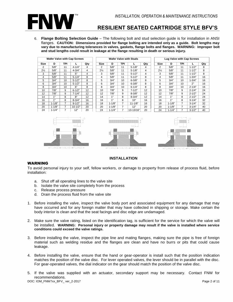
6. Flange Bolting Selection Guide – The following bolt and stud selection guide is for installation in ANSI flanges. CAUTION: Dimensions provided for flange bolting are intended only as a guide. Bolt lengths may vary due to manufacturing tolerances in valves, gaskets, flange bolts and flanges. WARNING: Improper bolt and stud lengths could result in leakage at the flange resulting in death or serious injury.
INSTALLATION
WARNING
To avoid personal injury to your self, fellow workers, or damage to property from release of process fluid, before installation:
a. Shut off all operating lines to the valve site b. Isolate the valve site completely from the process c. Release process pressure d. Drain the process fluid from the valve site
1. Before installing the valve, inspect the valve body port and associated equipment for any damage that may
have occurred and for any foreign matter that may have collected in shipping or storage. Make certain the body interior is clean and that the seat facings and disc edge are undamaged.
2. Make sure the valve rating, listed on the identification tag, is sufficient for the service for which the valve will
be installed. WARNING: Personal injury or property damage may result if the valve is installed where service conditions could exceed the valve ratings.
3. Before installing the valve, inspect the pipe line and mating flanges, making sure the pipe is free of foreign
material such as welding residue and the flanges are clean and have no burrs or pits that could cause leakage.
4. Before installing the valve, ensure that the hand or gear-operator is install such that the position indication
matches the position of the valve disc. For lever operated valves, the lever should be in parallel with the disc. For gear-operated valves, the dial indicator on the gear should match the position of the valve disc.
5. If the valve was supplied with an actuator, secondary support may be necessary. Contact FNW for
recommendations.
Wafer Valve with Studs
Size D TPI L Qty
2 5/8" 11 5-1/8" 4
2½ 5/8" 11 5-1/8" 4
3 5/8" 11 5-1/2" 4
4 5/8" 11 5-1/2" 8
5 3/4" 10 6-3/8" 8
6 3/4" 10 6-3/8" 8
8 3/4" 10 6-1/4" 8
10 7/8" 9 7-1/2" 12
12 7/8" 9 8-3/8" 12
14 1" 8 8-3/4" 12
16 1" 8 10" 16
18 1-1/8" 7 11-1/8" 16
20 1-1/8" 7 12" 20
24 1-1/4" 7 13-13/16" 20
Wafer Valve with Cap Screws
Size D TPI L Qty
2 5/8" 11 4-1/4" 4
2½ 5/8" 11 4-3/4" 4
3 5/8" 11 5" 4
4 5/8" 11 5-1/4" 8
5 3/4" 10 5-1/2" 8
6 3/4" 10 5-1/2" 8
8 3/4" 10 6" 8
10 7/8" 9 6-1/2" 12
12 7/8" 9 7-1/4" 12
14 1" 8 8" 12
16 1" 8 8-3/4" 16
18 1-1/8" 7 9-1/2" 16
20 1-1/8" 7 10-1/2" 20
24 1-1/4" 7 12" 20
Lug Valve with Cap Screws
Size D TPI L Qty
2 5/8" 11 1-1/2" 8
2½ 5/8" 11 1-1/2" 8
3 5/8" 11 1-1/2" 8
4 5/8" 11 1-3/4" 16
5 3/4" 10 1-3/4" 16
6 3/4" 10 2" 16
8 3/4" 10 2-1/4" 16
10 7/8" 9 2-1/4" 24
12 7/8" 9 2-1/2" 24
14 1" 8 2-1/2" 24
16 1" 8 3-1/4" 32
18 1-1/8" 7 3-1/4" 32
20 1-1/8" 7 3-1/4" 40
24 1-1/4" 7 3-1/2" 40
INSTALLATION, OPERATION & MAINTENANCE INSTRUCTIONS
RESILIENT SEATED CARTRIDGE STYLE BFV’S
DOC: IOM_FNW7xx_BFV_ ver_2-2017 Page 3 of 11
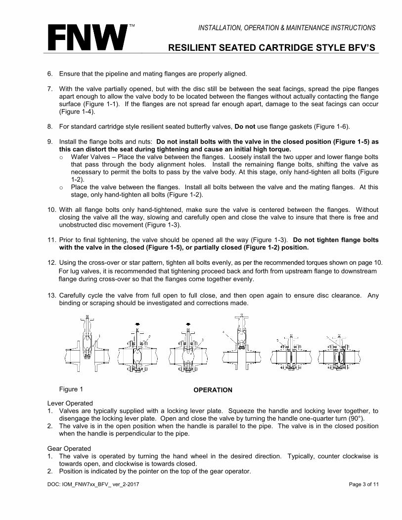
6. Ensure that the pipeline and mating flanges are properly aligned. 7. With the valve partially opened, but with the disc still be between the seat facings, spread the pipe flanges
apart enough to allow the valve body to be located between the flanges without actually contacting the flange surface (Figure 1-1). If the flanges are not spread far enough apart, damage to the seat facings can occur (Figure 1-4).
8. For standard cartridge style resilient seated butterfly valves, Do not use flange gaskets (Figure 1-6). 9. Install the flange bolts and nuts: Do not install bolts with the valve in the closed position (Figure 1-5) as
this can distort the seat during tightening and cause an initial high torque. o Wafer Valves – Place the valve between the flanges. Loosely install the two upper and lower flange bolts
that pass through the body alignment holes. Install the remaining flange bolts, shifting the valve as necessary to permit the bolts to pass by the valve body. At this stage, only hand-tighten all bolts (Figure 1-2).
o Place the valve between the flanges. Install all bolts between the valve and the mating flanges. At this stage, only hand-tighten all bolts (Figure 1-2).
10. With all flange bolts only hand-tightened, make sure the valve is centered between the flanges. Without
closing the valve all the way, slowing and carefully open and close the valve to insure that there is free and unobstructed disc movement (Figure 1-3).
11. Prior to final tightening, the valve should be opened all the way (Figure 1-3). Do not tighten flange bolts
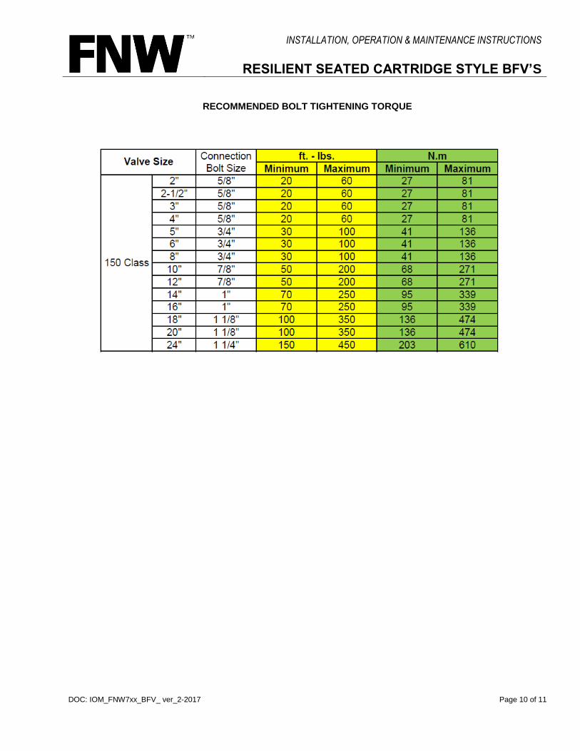
with the valve in the closed (Figure 1-5), or partially closed (Figure 1-2) position. 12. Using the cross-over or star pattern, tighten all bolts evenly, as per the recommended torques shown on page 10.
For lug valves, it is recommended that tightening proceed back and forth from upstream flange to downstream flange during cross-over so that the flanges come together evenly.
-
13. Carefully cycle the valve from full open to full close, and then open again to ensure disc clearance. Any
binding or scraping should be investigated and corrections made.
Figure 1
OPERATION Lever Operated 1. Valves are typically supplied with a locking lever plate. Squeeze the handle and locking lever together, to
disengage the locking lever plate. Open and close the valve by turning the handle one-quarter turn (90°). 2. The valve is in the open position when the handle is parallel to the pipe. The valve is in the closed position
when the handle is perpendicular to the pipe. Gear Operated 1. The valve is operated by turning the hand wheel in the desired direction. Typically, counter clockwise is
towards open, and clockwise is towards closed. 2. Position is indicated by the pointer on the top of the gear operator.

INSTALLATION, OPERATION & MAINTENANCE INSTRUCTIONS
RESILIENT SEATED CARTRIDGE STYLE BFV’S
DOC: IOM_FNW7xx_BFV_ ver_2-2017 Page 4 of 11
Note: Do not user cheater bars or lever extenders as damage can occur to internal components.
TROUBLESHOOTING
The following is intended as a guide only.
Trouble Probable Cause Remedy
The valve will not seal properly.
The seat and/or disc is worn or damaged.
Replace worn parts.
Foreign matter is present between seat and disc.
Operate several times to wipe clean.
Operator stops are not set properly. Adjust stops to proper setting.
The valve is hard to operate.
Build up of solids or roughness is on the edge of the disc.
Operate several times to wipe clean or disassemble valve and clean disc edge.
Operator is not installed Properly. Reinstall operator in proper alignment with valve stem.
Seat has chemically reacted (swelled) to process media.
Replace seat with material compatible to process fluid.
The valve will not open. Disc hits on ID of pipe. Check for proper pipe clearance and flange/pipe compatibility.
The valve is leaking around the stem.
The seat is damaged or worn. Replace seat.
The disc is bent. Replace disc, stems, bushing, and seat as required.
The flange seal is leaking.
Check for proper pipe alignment, flange, or flange seal damage. Prevent fluid from migrating behind seat and out stem.
The valve closes with line flow.
Handle or actuator does not provide proper restraint.
Restrain disc with handle or actuator.
The line flow rate is too high. Choose a larger valve or otherwise reduce flow to diminish effects of dynamic torque.
There is leakage at the flange.
The flange seal surface on seat is damaged.
Replace seat.
The flange surfaces are damaged or corroded.
Clean, repair, or replace flanges.
The flange bore is too large. Replace with proper flanges.
Clockwise rotation of gear-operator hand wheel opens valve. Open/Close indicators do not coincide with valve disc position.
The gear-operator has been rotated 90° on valve top. The hand wheel shaft aligns with the pipe (should be perpendicular).
Rotate the gear-operator 90° on the valve top to put the hand wheel shaft perpendicular to the pipe.
Automatic actuator slams valve closed or open.
Speed control valves are not present or need adjustment.
Install and/or adjust speed control valves.
Hard, soft or cracked seat damage is present.
Heat or chemical damage has occurred to seat.
Replace seat with material compatible to process fluid or correct offending fluid conditions.
INSTALLATION, OPERATION & MAINTENANCE INSTRUCTIONS
RESILIENT SEATED CARTRIDGE STYLE BFV’S
DOC: IOM_FNW7xx_BFV_ ver_2-2017 Page 5 of 11
MAINTENANCE Under normal operating conditions, these valves do not require periodic maintenance or lubrication. However, valve parts are subject to normal wear and must be periodically inspected and replaced as necessary. Inspection and maintenance frequency depends on the severity of the service conditions. This section includes assembly and disassembly instructions.
WARNING
To avoid personal injury to your self, fellow workers, or damage to property, prior to any maintenance, verify the following conditions.
a. Be sure the line is depressurized and drained. b. Be sure of the pipe line media. Proper care should be taken for protection against toxic and/or flammable
fluids. c. Never remove the valve without an operator (manual or automatic) already attached to the valve shaft. d. Never remove the operator from the valve while the valve is in the pipeline under pressure. e. Always be sure the disc is in the near closed position before removing the valve.
General The following periodic preventative maintenance practices are recommended for all resilient seated cartridge style butterfly valves. 1. Operate the valve from full open to full close to assure operability. 2. Check flange bolting for evidence of loosening and correct as needed. 3. Inspect the valve and surrounding area for previous or existing leakage at flange faces or shaft connections. 4. Check piping and/or wiring to actuator and related equipment for looseness and correct as needed. Butterfly Valve Assembly The following are general assembly instructions for all resilient seated cartridge style butterfly valves. General assembly diagrams are provided at the end of this document. Prior to assembly, note the following. 1. Materials and number of parts can vary by size and configuration. 2. Use of a lubricant is recommended for assembly. Make sure the lubricant used is compatible with the valve
materials and the service the valve will be used in. 3. Component tolerances can be rather tight. It may be necessary, depending on the size of valve, to use
mechanical means to assemble all components. 4. Make sure that all components are present and undamaged prior to assembly.
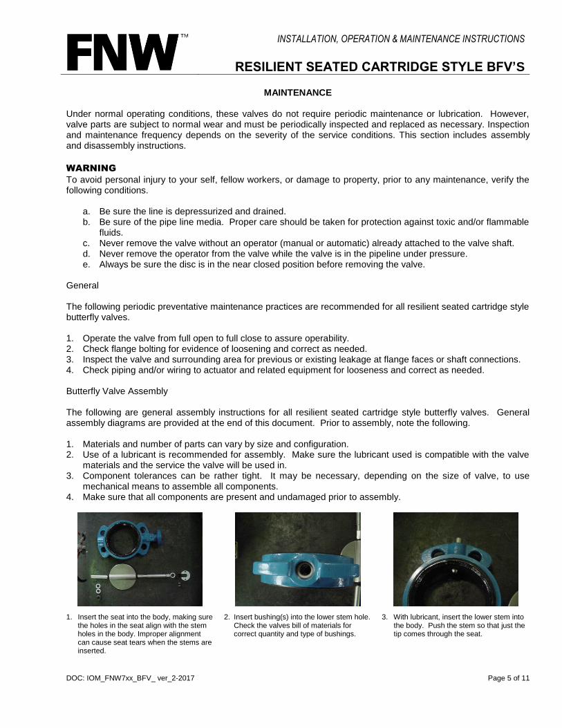
1. Insert the seat into the body, making sure the holes in the seat align with the stem holes in the body. Improper alignment can cause seat tears when the stems are inserted.
2. Insert bushing(s) into the lower stem hole. Check the valves bill of materials for correct quantity and type of bushings.
3. With lubricant, insert the lower stem into the body. Push the stem so that just the tip comes through the seat.

INSTALLATION, OPERATION & MAINTENANCE INSTRUCTIONS
RESILIENT SEATED CARTRIDGE STYLE BFV’S
DOC: IOM_FNW7xx_BFV_ ver_2-2017 Page 6 of 11
4. Insert the bottom of the disc (markings on the disc are typically upside down) into the seat over the lower stem. With the disc in the partially open position, push or tap the top of the disc to align with the upper stem hole.
5. Insert the lower stem into the disc by pushing the valve body/disc assembly down onto the stem. Then tap the lower stem further in beneath the internal threads in the body.
6. Insert bushing(s) into the upper stem hole. Note that 14” and larger valves have a long bushing that should be installed first.
7. Insert o-ring packing. Note that on 14” and larger valves, the o-ring is installed between the upper two bushings.
8. With lubricant, insert the upper stem almost all the way into the body. Make sure the stem flats are aligned with the receiving hole in the disc.
9. If necessary, drive the upper stem into the disc with a rubber mallet. If there is much resistance, make sure the stem flats are aligned appropriately to the disc.
10. Slide the retaining plate onto the groove located just below the square drive of the stem. Align the screw holes with the holes in the body’s top flange.
11. With a rubber mallet, tap the upper stem the remainder of the way into the stem. Secure the retainer plate with flat head counter-sunk screws.
12. Insert the lower stem plug by first applying pipe-dope, Loctite®, or an equivalent product to secure the plug.
13. Screw the lower stem plug in place using a hex wrench. Do not over-tighten the plug on lower stem.
14. If facilities are available, test the valve for torque and shutoff.
15. The valve is now complete and ready for installation of hand lever or gear operator.

INSTALLATION, OPERATION & MAINTENANCE INSTRUCTIONS
RESILIENT SEATED CARTRIDGE STYLE BFV’S
DOC: IOM_FNW7xx_BFV_ ver_2-2017 Page 7 of 11
Operators 16a. Levers 1. Install the locking lever plate over
the stem. There are two styles, one that uses bolt and washers, another that use friction tabs. Friction tabs may need to be slightly twisted for a new hold.
2. Install lever over stem and tighten set screw.
3. For 2” to 8” valves, install the lever washer and bolt.
4. Ensure that the close position of the lever closes the valve and tighten all bolts.
16b. Gears 1. The hand wheel shaft should be
perpendicular to the pipe after installation.
2. Make sure the gear position matches the position of the valve. Position is indicated on the top plate of the gear.
3. If there is a make-up sleeve for the stem, place it over the stem at this time.
4. Set the gear on the stem and secure with bolts and lock washers.
5. Ensure that the disc is fully closed when the gear-operator is in the closed position. Adjust as needed.
Butterfly Valve Disassembly The valve can be disassembled in the reverse order of the assembly instructions. Note the following to ease disassembly and to help protect valve components. 1. Materials and number of parts can vary by size and configuration. 2. Use of a lubricant is recommended for disassembly of disc from seat. Make sure the lubricant used is
compatible with the valve materials and the service the valve is used in. 3. Component tolerances can be rather tight. It may be necessary, depending on the size of valve, to use
mechanical means to remove all components. 4. Make sure a clean area is available to work in and to place disassembled parts. 5. Parts should be protected from dirt, dust, and possible damage.

INSTALLATION, OPERATION & MAINTENANCE INSTRUCTIONS
RESILIENT SEATED CARTRIDGE STYLE BFV’S
DOC: IOM_FNW7xx_BFV_ ver_2-2017 Page 8 of 11
ASSEMBLY VIEW The following assembly view shows general construction of the resilient seated cartridge style butterfly valve. For specific materials, component quantities and component location, consult the valve dimensional drawings.
14"-24"
2"-12"
SEAT
INTEGRAL O-RINGS
PLUG
BUSHING(S)
LOWER STEM
UPPER STEM
BUSHING(S)
O-RING PACKING
RETAINER PLATE
WAFER BODY
LUG BODY
FLANGE
SEAT
SUPPORT RING
BODY
SEAT
SUPPORT RING
BODY
INTEGRAL O-RINGS
RTFE SEATS
EPDM / BUNA SEATS
SEAT AND SUPPORT RING
ARE INTEGRAL COMPONENTS
SEATS HAVE RESILIENT
SEALING SURFACE
SEATS HAVE INTEGRAL
O-RING SEAL
NEWER MODEL VALVES USE
FRICTION TABS INSTEAD OF BOLTS
TO SECURE THE LOCKING LEVER
PLATE TO THE TOP FLANGE.
INSTALLATION, OPERATION & MAINTENANCE INSTRUCTIONS
RESILIENT SEATED CARTRIDGE STYLE BFV’S
DOC: IOM_FNW7xx_BFV_ ver_2-2017 Page 9 of 11
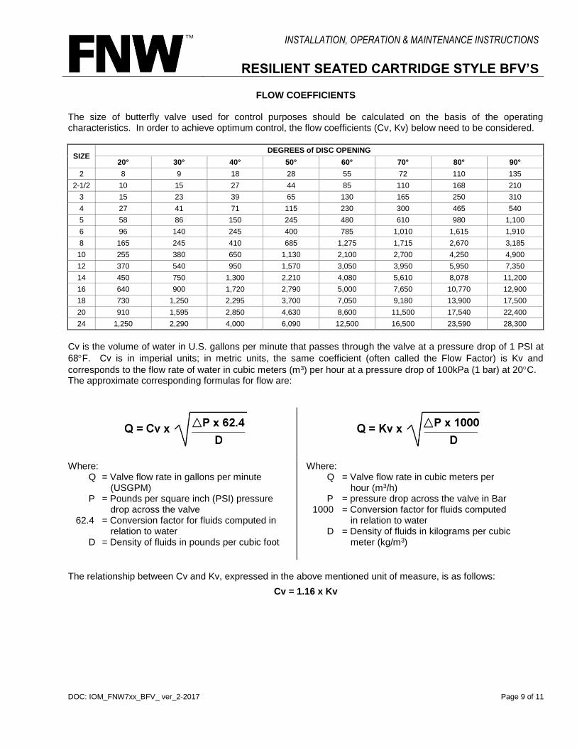
FLOW COEFFICIENTS The size of butterfly valve used for control purposes should be calculated on the basis of the operating characteristics. In order to achieve optimum control, the flow coefficients (Cv, Kv) below need to be considered.
SIZE DEGREES of DISC OPENING
20° 30° 40° 50° 60° 70° 80° 90°
2 8 9 18 28 55 72 110 135
2-1/2 10 15 27 44 85 110 168 210
3 15 23 39 65 130 165 250 310
4 27 41 71 115 230 300 465 540
5 58 86 150 245 480 610 980 1,100
6 96 140 245 400 785 1,010 1,615 1,910
8 165 245 410 685 1,275 1,715 2,670 3,185
10 255 380 650 1,130 2,100 2,700 4,250 4,900
12 370 540 950 1,570 3,050 3,950 5,950 7,350
14 450 750 1,300 2,210 4,080 5,610 8,078 11,200
16 640 900 1,720 2,790 5,000 7,650 10,770 12,900
18 730 1,250 2,295 3,700 7,050 9,180 13,900 17,500
20 910 1,595 2,850 4,630 8,600 11,500 17,540 22,400
24 1,250 2,290 4,000 6,090 12,500 16,500 23,590 28,300
Cv is the volume of water in U.S. gallons per minute that passes through the valve at a pressure drop of 1 PSI at
68F. Cv is in imperial units; in metric units, the same coefficient (often called the Flow Factor) is Kv and
corresponds to the flow rate of water in cubic meters (m3) per hour at a pressure drop of 100kPa (1 bar) at 20C. The approximate corresponding formulas for flow are:
Where: Q = Valve flow rate in gallons per minute (USGPM) P = Pounds per square inch (PSI) pressure drop across the valve
62.4 = Conversion factor for fluids computed in relation to water
D = Density of fluids in pounds per cubic foot
Where: Q = Valve flow rate in cubic meters per hour (m3/h) P = pressure drop across the valve in Bar
1000 = Conversion factor for fluids computed in relation to water
D = Density of fluids in kilograms per cubic meter (kg/m3)
The relationship between Cv and Kv, expressed in the above mentioned unit of measure, is as follows:
Cv = 1.16 x Kv
INSTALLATION, OPERATION & MAINTENANCE INSTRUCTIONS
RESILIENT SEATED CARTRIDGE STYLE BFV’S
DOC: IOM_FNW7xx_BFV_ ver_2-2017 Page 10 of 11
RECOMMENDED BOLT TIGHTENING TORQUE
INSTALLATION, OPERATION & MAINTENANCE INSTRUCTIONS
RESILIENT SEATED CARTRIDGE STYLE BFV’S
DOC: IOM_FNW7xx_BFV_ ver_2-2017 Page 11 of 11
WARRANTY
1. LIMITED WARRANTY: Subject to the limitations expressed herein, Seller warrants that products manufactured by Seller shall be free from defects in design, material and workmanship under normal use for a period of one (1) year from installation but in no case shall the warranty period extend longer than eighteen months from the date of sale. This warranty is void for any damage caused by misuse, abuse, neglect, acts of God, or improper installation. For the purpose of this section, “Normal Use” means in strict accordance with the installation, operation and maintenance manual. The warranty for all other products is provided by the original equipment manufacturer.
2. REMEDIES: Seller shall repair or replace, at its option, any non-conforming or otherwise defective product, upon receipt of notice from Buyer during the Manufacturer’s warranty period at no additional charge. SELLER HEREBY DISCLAIMS ALL OTHER EXPRESSED OR IMPLIED WARRANTIES, INCLUDING, WITHOUT LIMITATION, ALL IMPLIED WARRANTIES OF MERCHANTABILITY AND FITNESS OR FITNESS FOR A PARTICULAR PURPOSE.
3. LIMITATION OF LIABILITY: UNDER NO CIRCUMSTANCES SHALL EITHER PARTY BE LIABLE TO THE OTHER FOR INCIDENTAL, PUNITIVE, SPECIAL OR CONSEQUENTIAL DAMAGES OF ANY KIND. BUYER HEREBY ACKNOWLEDGES AND AGREES THAT UNDER NO CIRCUMSTANCES, AND IN NO EVENT, SHALL SELLER'S LIABILITY, IF ANY, EXCEED THE NET SALES PRICE OF THE DEFECTIVE PRODUCT(S) PURCHASED DURING THE PREVIOUS CONTRACT YEAR.
4. LABOR ALLOWANCE: Seller makes NO ADDITIONAL ALLOWANCE FOR THE LABOR OR EXPENSE OF REPAIRING OR REPLACING DEFECTIVE PRODUCTS OR WORKMANSHIP OR DAMAGE RESULTING FROM THE SAME.
5. RECOMMENDATIONS BY SELLER: Seller may assist Buyer in selection decisions by providing information regarding products that it manufacturers and those manufactured by others. However, Buyer acknowledges that Buyer ultimately chooses the product’s suitability for its particular use, as normally signified by the signature of Buyer’s technical representative. Any recommendations made by Seller concerning the use, design, application or operation of the products shall not be construed as representations or warranties, expressed or implied. Failure by Seller to make recommendations or give advice to Buyer shall not impose any liability upon Seller.
6. EXCUSED PERFORMANCE: Seller will make a good faith effort to complete delivery of the products as indicated by Seller in writing, but Seller assumes no responsibility or liability and will accept no back-charge for loss or damage due to delay or inability to deliver, caused by acts of God, war, labor difficulties, accidents, inability to obtain materials, delays of carriers, contractors or suppliers or any other causes of any kind whatever beyond the control of Seller. Under no circumstances shall Seller be liable for any special, consequential, incidental, or indirect damages, losses, or expense (whether or not based on negligence) arising directly or indirectly from delays or failure to give notice of delay.