residential distributed generation with optional energy
TRANSCRIPT

March 2018
Residential Distributed Generation with Optional Energy Storage Systems

ENGINEERING SPECIFICATION
No. T014 Page 1 of 20
REV. 2 DATE: 03-01-18 CATEGORY
ELECTRIC SERVICE REQUIREMENTS SUBJECT
RESIDENTIAL DISTRIBUTED GENERATION (DG) WITH OPTIONAL ENERGY STORAGE SYSTEMS (E.G., BATTERIES)
TABLE OF CONTENTS
1. Overview ................................................................................................................... 2
2. General Requirements for Service ............................................................................. 3
3. Definitions ................................................................................................................... 3
4. Abbreviations ............................................................................................................... 5
5. References – Latest Editions, Errata, Corrections, and Amendments .................. 5
6. Design Review and Approval ..................................................................................... 6
7. SMUD Requirements ................................................................................................... 8
8. Power Production Metering Requirements - General ............................................ 17
9. AC Disconnects (where applicable) ......................................................................... 18
10. Labeling ................................................................................................................. 18
Example of panel types * ................................................................................................. 18
Figure 3 - Sample Site Plan (Partial View) ...................................................................... 19
Figure 4 - Sample Cut Sheet PV Connected Between Meter and Main Breaker ......... 19

ENG. SPEC.
T014
REV. 2
ELECTRIC SERVICE REQUIREMENTS RESIDENTIAL DISTRIBUTED GENERATION (DG)
WITH OPTIONAL ENERGY STORAGE SYSTEMS (E.G., BATTERIES)
Page 2
of 20
1. Overview
This document is intended to present the Sacramento Municipal Utility District's (SMUD's) requirements for the establishment of connecting Residential Distributed Generation (DG) to SMUD’s electric grid with the option to also install Energy Storage System (ESS) devices (e.g., batteries). This document exists on SMUD.org – search for “Electric Service Requirements”.
If you are a Residential Customer served via our Downtown Secondary Network, in addition to the requirements set forth in this document, you will also have to abide by the requirements of SMUD’s GP-001, Distribution Generation (DG) Interconnection Requirements on the Downtown Secondary Network System.
All references to inverter-based DG and/or ESS system sizes will be based upon total nameplate AC rating of the inverter(s).
The requirements presented here are necessary for SMUD to supply uniform, satisfactory, and safe electrical connections between the Customer’s DG and/or ESS, and SMUD’s electrical system. It is necessary that all written material (this text, as well as all of the notes on the drawings) be carefully read.
The National Electric Code (NEC) and the County / City Electrical Inspector for your area may have requirements for your generation
system that are beyond what SMUD requires. Please check with your local Inspector to make sure your plans meet their requirements.
SAFETY FIRST!! All materials used, and all work performed, on a Customer's premise (with the exception of the meter), shall conform with requirements of the local inspection authority, the National Electric Code, and all applicable safety orders, rules, and regulations of the State of California. Customer service switchboard equipment shall meet SMUD and EUSERC (The Electric Utility Service Equipment Requirements Committee) requirements and be UL approved. No DG and/or ESS can be connected unless approved by the County / City Electrical Inspector for your area (also referred to as the Authority Having Jurisdiction or AHJ). In order to provide a safe interconnection between the Residential DG and/or ESS and SMUD’s electrical system, a SMUD representative will also have to inspect and approve the DG and/or ESS installation.
ENG. SPEC.
T014
REV. 2
ELECTRIC SERVICE REQUIREMENTS RESIDENTIAL DISTRIBUTED GENERATION (DG)
WITH OPTIONAL ENERGY STORAGE SYSTEMS (E.G., BATTERIES)
Page 3
of 20
2. General Requirements for Service
Portions of Sections 3 through 9 below are modified from the 2015 edition of EUSERC - The Electric Utility Service Equipment Requirements Committee.
3. Definitions
3.1. Combiner / Sub-Panel: an electrical panel where one or more feeds from Distributed Generation sources can be combined into one circuit to the Power Production Meter. If the Combiner / Sub-Panel has more than six (6) breakers, an additional Visible Disconnect Device will have to be installed between the Combiner / Sub-Panel and the Power Production Meter (2017 NEC 230.70(A) for Service Conductors and 240.92(D)2 for Feeder Conductors). Further, the Combiner / Sub-Panel shall be sized to only accommodate the DG and/or ESS breakers. If a larger sized Combiner / Sub-Panel is used, then the panel shall be rendered unable to accept any additional breakers for unrelated loads. The allowed related loads can include tracking motors, cooling fans, monitoring and metering, etc. Note: Generation connected between the meter and the main (Option 2) may only include monitoring and metering per 2017 NEC 230.82.
3.2. Critical Load Sub-Panel: an electrical panel where customer essential loads are connected and which is served by an on-site Energy Storage System.
3.3. DG (Distributed Generation): Any type of Customer owned electric generator, static inverter, or generating facility that has the capability of being operated in parallel with SMUD’s distribution system.
3.4. Distribution System: All electrical wires, equipment, and other facilities owned or provided by SMUD, including Interconnection Facilities, by which SMUD provides Distribution Service to a Customer.
3.5. Energy Storage System: a system that uses either chemical means (e.g., batteries) or mechanical means (e.g., flywheels) to store energy for later use. The system will include all necessary equipment necessary to convert the storage means into usable energy (e.g., wires, inverters, chargers, gearboxes, motor/gen set, etc.).
3.6. EUSERC: The Electric Utility Service Equipment Requirements Committee. Designation that metering equipment meets the requirements of the member utilities developed to promote safe and uniform electric service equipment requirements.

ENG. SPEC.
T014
REV. 2
ELECTRIC SERVICE REQUIREMENTS RESIDENTIAL DISTRIBUTED GENERATION (DG)
WITH OPTIONAL ENERGY STORAGE SYSTEMS (E.G., BATTERIES)
Page 4
of 20
3.7. Generating Facility: All Generators, electrical wires, equipment, and other facilities, owned or provided by the facility owner, for the purpose of producing electric power.
3.8. Interactive Static Inverter: A power electronic device that converts Direct Current (DC) power to Alternating Current (AC) by means of electronic switching. The only static inverters acceptable for the interconnection of Customer owned equipment with SMUD are those inverters that are designed to automatically separate from SMUD’s distribution system upon loss of voltage from SMUD and to reclose with SMUD only after SMUD’s voltage has been restored.
3.9. Parallel Operation: The simultaneous operation of a Generator with power delivered or received by SMUD while interconnected. Under SMUD’s Rate Policy and Procedures Manual, No. 11-01, “Interconnection Guidelines”, Parallel Operation includes only those generators that are so interconnected with the Distribution System for more than one second (60 cycles).
3.10. Point of Common Coupling (PCC): The transfer point for electricity between the electrical conductors of SMUD and the electrical conductors of the Generating Facility.
3.11. Point of Interconnection (Delivery): The electrical transfer point between a Generator or a Generating Facility and SMUD’s electrical system. This may or may not be coincident with the Point of Common Coupling.
3.12. Power Production Meter (PM): The meter located at the Generator panel, or otherwise located to record generation output without other unrelated Customer loads. Loads ancillary to the generation (e.g., solar tracker motors, engine cooling fans, pumps, etc.) are to be connected, to the extent practicable, so that these are metered with the generation by the Power Production Meter, i.e., the ancillary loads should be connected between the DG and the Power Production Meter. All PM panels shall be of ring type.
3.13. Smart Contactor: a device that will automatically disconnect an Energy Storage system from the host electric utility upon detection of the loss of voltage from the utility.
3.14. Utility Service Meter: The meter located in a Customer’s main electrical panel. This meter is capable of separately recording power flow into, and power flow out of, a Customer’s facility or premise.
3.15. Visible Disconnect Device: An electrical switching device that can separate the Generating Facility from SMUD’s Distribution System and is designed to allow visible verification that separation has been accomplished. This
ENG. SPEC.
T014
REV. 2
ELECTRIC SERVICE REQUIREMENTS RESIDENTIAL DISTRIBUTED GENERATION (DG)
WITH OPTIONAL ENERGY STORAGE SYSTEMS (E.G., BATTERIES)
Page 5
of 20
requirement can be met by opening the enclosure to observe the contact separation. It will be used by SMUD and the Customer to establish an open point when working on either the Power Production Meter or the DG and/or ESS system. With the door open, the air gap shall be visible at the trailing edge of the movable disconnect blades when the switch is in the open position. It will completely isolate the Customer’s generating facility from SMUD’s distribution grid. A Combiner / Sub-Panel may be substituted for a Visible Disconnect.
4. Abbreviations
AC = Alternating Current ESR = Electric Service Requirement AHJ = Authority Having Jurisdiction LEC = Local Exchange Carrier CEC = California Electric Code NEC = 2017 National Electric Code CL = Critical Loads NEM = Net Energy Metering DC = Direct Current PCC = Point of Common Coupling DG = Distributed Generation PM = Power Production Meter ESS = Energy Storage System VDD = Visible Disconnect Device
5. References – Latest Editions, Errata, Corrections, Bulletins, and Amendments
All Customer equipment shall conform to nationally recognized standards and recommended practices. These include, but are not limited to the following:
5.1. California Electrical Code (CEC)
5.2. IEEE 519 – Recommended Practice and Requirements for Harmonic Control in Electrical Power Systems
5.3. IEEE 929 – Recommended Practice for Utility Interface of Photovoltaic (PV) Systems
5.4. IEEE 1547 – Standard for Interconnecting Distributed Resources with Electric Power Systems
5.5. IEEE 1547.1 – Standard for Conformance Test Procedures for Equipment Interconnecting Distributed Resources with Electric Power Systems
5.6. NEMA C84.1 - Electric Power Systems and Equipment-Voltage Ratings (60 Hertz) {formerly ANSI C84.1}
5.7. NFPA 70 – 2017 National Electrical Code (NEC), especially Articles 690, 705, 706, 708, and 710.
5.8. OSHA 1910.145(F)(7)

ENG. SPEC.
T014
REV. 2
ELECTRIC SERVICE REQUIREMENTS RESIDENTIAL DISTRIBUTED GENERATION (DG)
WITH OPTIONAL ENERGY STORAGE SYSTEMS (E.G., BATTERIES)
Page 6
of 20
5.9. UL 98 – UL Standard for Safety Enclosed and Dead-Front Switches
5.10. UL 1741 – UL Standard for Safety Inverters, Converters, Controllers and Interconnection System Equipment for Use with Distributed Energy Resources
6. Design Review and Approval 6.1. Prior to APPROVAL of Customer interconnection facilities, the Customer shall
submit a:
6.1.1. Distributed Generation (DG) and/or Energy Storage System (ESS) interconnection on-line application for SMUD's review and written approval,
6.1.2. An electrical one-line or three-line diagram,
6.1.3. A site plan/layout showing the location of all electrical equipment from the inverter (including solar equipment or other generation equipment to be listed) and/or ESS back to the Main electric service panel.
6.1.4. SMUD will not be responsible for the costs incurred by the Customer for the relocation or replacement of any equipment installed by the Customer prior to SMUD’s approval.
6.2. All metering equipment shall meet requirements set forth by EUSERC; SMUD's ESR’s T002 and T003; SMUD Policy and Procedure 11-01, Interconnection Guideline; and to this ESR T014.
6.3. Changes or modifications to the approved design shall not be made without prior approval. If changes or modifications are desired, the Customer shall submit the revised plans including the changes or modifications for SMUD approval.
6.4. The accuracy of the Power Production Meter to monitor the true output of the DG system is very important to SMUD. Therefore, no other loads can be connected between the Power Production Meter and the DG equipment. The allowed related loads can include tracking motors, cooling fans, monitoring and metering, etc. Note: Generation connected between the meter and the main (Option 2) may only include monitoring and metering per 2017 NEC 230.82. Please reference on your design that the Combiner / Sub-Panel will be sized to only accommodate the DG and/or ESS breakers. If a larger sized Combiner / Sub-Panel is used, then the panel shall be rendered unable to accept any additional breakers or loads. The equipment needs to be called out on the drawing with the following text “DG load center sized for DG breakers only or rendered unable to accept additional loads”.
ENG. SPEC.
T014
REV. 2
ELECTRIC SERVICE REQUIREMENTS RESIDENTIAL DISTRIBUTED GENERATION (DG)
WITH OPTIONAL ENERGY STORAGE SYSTEMS (E.G., BATTERIES)
Page 7
of 20
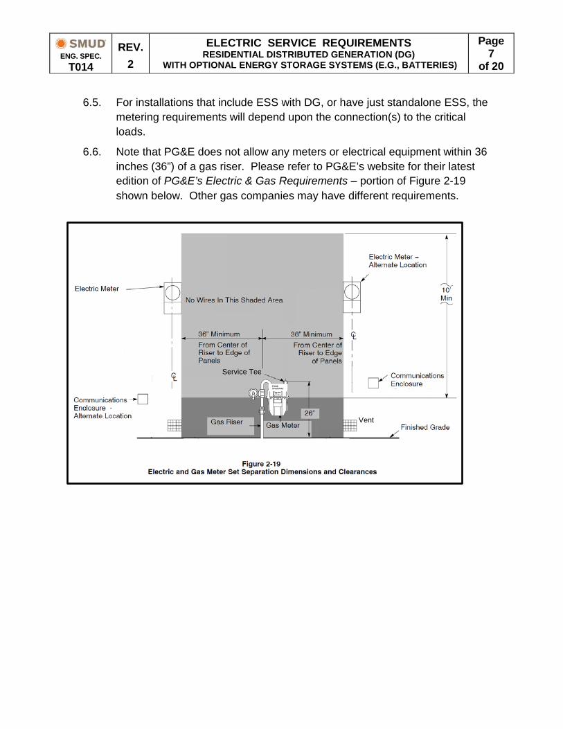
6.5. For installations that include ESS with DG, or have just standalone ESS, the metering requirements will depend upon the connection(s) to the critical loads.
6.6. Note that PG&E does not allow any meters or electrical equipment within 36 inches (36”) of a gas riser. Please refer to PG&E’s website for their latest edition of PG&E’s Electric & Gas Requirements – portion of Figure 2-19 shown below. Other gas companies may have different requirements.
Vent
Service Tee
ENG. SPEC.
T014
REV. 2
ELECTRIC SERVICE REQUIREMENTS RESIDENTIAL DISTRIBUTED GENERATION (DG)
WITH OPTIONAL ENERGY STORAGE SYSTEMS (E.G., BATTERIES)
Page 8
of 20
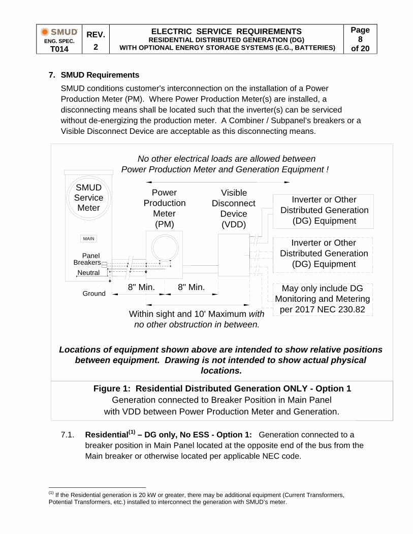
7. SMUD Requirements SMUD conditions customer’s interconnection on the installation of a Power Production Meter (PM). Where Power Production Meter(s) are installed, a disconnecting means shall be located such that the inverter(s) can be serviced without de-energizing the production meter. A Combiner / Subpanel’s breakers or a Visible Disconnect Device are acceptable as this disconnecting means.
7.1. Residential(1) – DG only, No ESS - Option 1: Generation connected to a
breaker position in Main Panel located at the opposite end of the bus from the Main breaker or otherwise located per applicable NEC code.
(1) If the Residential generation is 20 kW or greater, there may be additional equipment (Current Transformers, Potential Transformers, etc.) installed to interconnect the generation with SMUD’s meter.
8" Min. 8" Min.
Generation connected to Breaker Position in Main Panelwith VDD between Power Production Meter and Generation.
MAIN
SMUDServiceMeter
Figure 1: Residential Distributed Generation ONLY - Option 1
PanelBreakers
Neutral
Ground
No other electrical loads are allowed betweenPower Production Meter and Generation Equipment !
PowerProduction
Meter(PM)
VisibleDisconnect
Device(VDD)
Locations of equipment shown above are intended to show relative positionsbetween equipment. Drawing is not intended to show actual physical
locations.
Within sight and 10' Maximum withno other obstruction in between.
Inverter or OtherDistributed Generation
(DG) Equipment
Inverter or OtherDistributed Generation
(DG) Equipment
May only include DGMonitoring and Meteringper 2017 NEC 230.82
ENG. SPEC.
T014
REV. 2
ELECTRIC SERVICE REQUIREMENTS RESIDENTIAL DISTRIBUTED GENERATION (DG)
WITH OPTIONAL ENERGY STORAGE SYSTEMS (E.G., BATTERIES)
Page 9
of 20
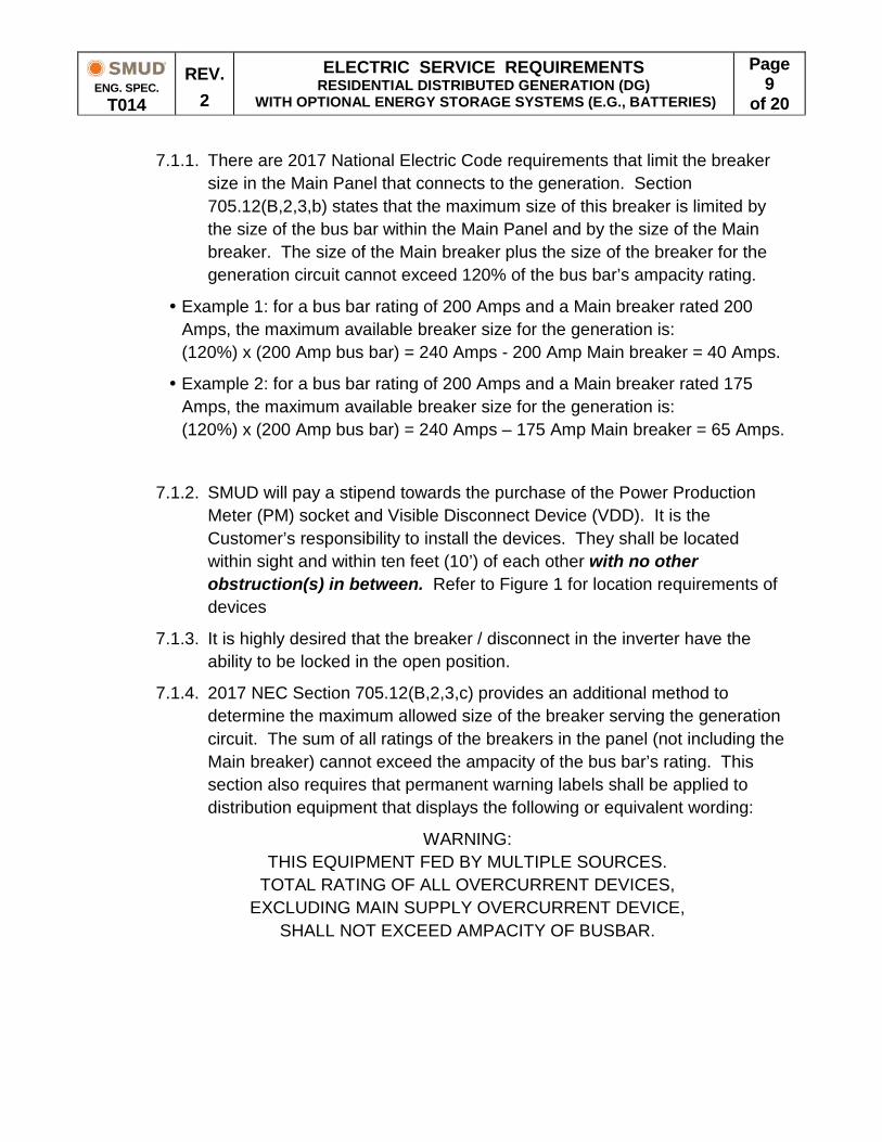
7.1.1. There are 2017 National Electric Code requirements that limit the breaker size in the Main Panel that connects to the generation. Section 705.12(B,2,3,b) states that the maximum size of this breaker is limited by the size of the bus bar within the Main Panel and by the size of the Main breaker. The size of the Main breaker plus the size of the breaker for the generation circuit cannot exceed 120% of the bus bar’s ampacity rating.
Example 1: for a bus bar rating of 200 Amps and a Main breaker rated 200 Amps, the maximum available breaker size for the generation is: (120%) x (200 Amp bus bar) = 240 Amps - 200 Amp Main breaker = 40 Amps.
Example 2: for a bus bar rating of 200 Amps and a Main breaker rated 175 Amps, the maximum available breaker size for the generation is: (120%) x (200 Amp bus bar) = 240 Amps – 175 Amp Main breaker = 65 Amps.
7.1.2. SMUD will pay a stipend towards the purchase of the Power Production Meter (PM) socket and Visible Disconnect Device (VDD). It is the Customer’s responsibility to install the devices. They shall be located within sight and within ten feet (10’) of each other with no other obstruction(s) in between. Refer to Figure 1 for location requirements of devices
7.1.3. It is highly desired that the breaker / disconnect in the inverter have the ability to be locked in the open position.
7.1.4. 2017 NEC Section 705.12(B,2,3,c) provides an additional method to determine the maximum allowed size of the breaker serving the generation circuit. The sum of all ratings of the breakers in the panel (not including the Main breaker) cannot exceed the ampacity of the bus bar’s rating. This section also requires that permanent warning labels shall be applied to distribution equipment that displays the following or equivalent wording:
WARNING: THIS EQUIPMENT FED BY MULTIPLE SOURCES.
TOTAL RATING OF ALL OVERCURRENT DEVICES, EXCLUDING MAIN SUPPLY OVERCURRENT DEVICE,
SHALL NOT EXCEED AMPACITY OF BUSBAR.

ENG. SPEC.
T014
REV. 2
ELECTRIC SERVICE REQUIREMENTS RESIDENTIAL DISTRIBUTED GENERATION (DG)
WITH OPTIONAL ENERGY STORAGE SYSTEMS (E.G., BATTERIES)
Page 10
of 20
7.1.5. The 2017 NEC has a requirement for the labeling of the breaker that connects to the generation source. Section 705.12(B,2,3,b) states “A permanent warning label shall be applied to the distribution equipment adjacent to the back-fed breaker from the inverter that displays the following or equivalent wording:
WARNING: POWER SOURCE OUTPUT CONNECTION -
DO NOT RELOCATE THIS OVERCURRENT DEVICE.
7.1.6. As mentioned earlier, the NEC and the County / City Electrical Inspector for your area may have requirements for your generation system that are beyond what is listed here. Please check with your local Inspector to make sure your plans meet their requirements.

ENG. SPEC.
T014
REV. 2
ELECTRIC SERVICE REQUIREMENTS RESIDENTIAL DISTRIBUTED GENERATION (DG)
WITH OPTIONAL ENERGY STORAGE SYSTEMS (E.G., BATTERIES)
Page 11
of 20
7.2. Residential – DG Only, No ESS – Option 2: Generation circuit is connected between SMUD’s Utility Service Meter and the Panel’s Main breaker. A FUSED Disconnect Switch needs to be installed between the Main Panel and the Power Production Meter (2017 NEC 230). All other items from 7.1.2 through 7.1.6 apply. Note: Energy Storage Systems (e.g., batteries) that charge from utility AC power are considered LOADS, and these loads are not included in those permitted by NEC 230.82(5). As such, these storage systems may NOT be connected in this location. Energy Storage Systems that are configured to only charge from some other source (such as the DC bus of a PV system) are considered generation, and may connect in this location per NEC 230.82(6).
7.2.1. The FUSED Disconnect Switch should be as close as possible to the Main Panel, and it is recommended that it be within ten feet (10’) of the Main Panel. Please consult with the AHJ as to the maximum distance allowed from the Main Panel.
8" Min.8" Min.
Generation connected between Main Breaker and SMUD Utility Service Meterwith Visible Disconnect Device between Power Production Meter and Generation.
MAIN
SMUDServiceMeter
Figure 2: Residential Distributed Generation ONLY- NO ESS - Option 2
FUSEDDisconnect
Switch
8" Min.
No other electrical loads are allowed betweenPower Production Meter and Generation Equipment !
Neutral
Ground
PowerProduction
Meter(PM)
VisibleDisconnect
Device(VDD)
Locations of equipment shown above are intended to show relative positions betweenequipment. Drawing is not intended to show actual physical locations.
Within sight and 10' Maximum withno other obstruction in between.
Inverter or OtherDistributed Generation
(DG) EquipmentNO ESS ALLOWEDAHEAD OF MAIN
BREAKER
Inverter or OtherDistributed Generation
(DG) EquipmentMay only include DG
Monitoring and Meteringper 2017 NEC 230.82
10' MaximumRecommended

ENG. SPEC.
T014
REV. 2
ELECTRIC SERVICE REQUIREMENTS RESIDENTIAL DISTRIBUTED GENERATION (DG)
WITH OPTIONAL ENERGY STORAGE SYSTEMS (E.G., BATTERIES)
Page 12
of 20
7.2.2. 2017 NEC section 705.12(A) states “The sum of the ratings of all overcurrent devices connected to the power production sources shall not exceed the rating of the service.”
7.3. Residential – DG and ESS – Option 3: Generation connected to a breaker position in a Critical Load panel with an ESS connected to a separate breaker position in the Critical Load panel.
7.3.1. As with previous options, there can be no other load between the Power
Product Meter and the DG equipment, other than loads necessary for the monitoring and metering of the DG equipment.
7.3.2. A Smart Contactor needs to be installed between the Main Panel and the Critical Load Panel. This contactor will open and isolate the DG and ESS from the Utility System should the Utility System experience an outage. This will allow the DG and ESS to continue to power the Critical Loads.
PanelBreakers
8" Min.MAINPANEL
VisibleDisconnect
Device(VDD)
Sub-Meter forPower
Production (PPM)
Neutral
Ground
SMUDServiceMeter
Inverter or OtherDistributed
Generation (DG)Equipment
Within sight and 10' Maximum withno other obstructions in between.
May only includeDG Monitoringand Meteringper 2017 NEC
230.82.
No other electrical loads are allowed betweenPower Production Meter and Generation Equipment !
SmartContactor
(SC)
CriticalLoadPanel
CriticalLoads
VisibleDisconnect
Device(VDD)
Sub-Meter for Energy Storage (ESSM) not required onstorage equipment if Customer is participating in SMUD's
energy storage program.Customer is responsible for joining the program before the
system will be allowed to be energized.
Ground
Energy StorageSystem
Equipment
Figure 3: Residential Distributed Generation with Energy Storage Equipment - Option 3
Generation connected to Breaker Position in Critical Load Panelwith ESS connected to a Different Breaker Position in Critical Load Panel.
ENG. SPEC.
T014
REV. 2
ELECTRIC SERVICE REQUIREMENTS RESIDENTIAL DISTRIBUTED GENERATION (DG)
WITH OPTIONAL ENERGY STORAGE SYSTEMS (E.G., BATTERIES)
Page 13
of 20
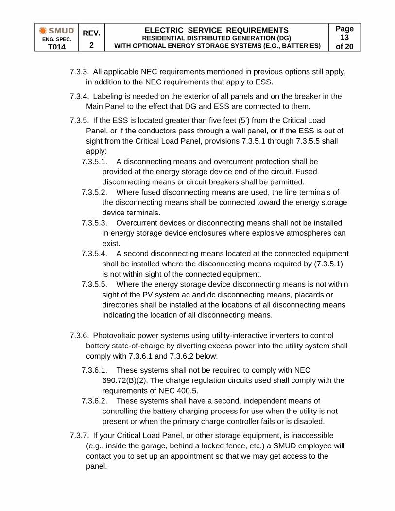
7.3.3. All applicable NEC requirements mentioned in previous options still apply, in addition to the NEC requirements that apply to ESS.
7.3.4. Labeling is needed on the exterior of all panels and on the breaker in the Main Panel to the effect that DG and ESS are connected to them.
7.3.5. If the ESS is located greater than five feet (5’) from the Critical Load Panel, or if the conductors pass through a wall panel, or if the ESS is out of sight from the Critical Load Panel, provisions 7.3.5.1 through 7.3.5.5 shall apply:
7.3.5.1. A disconnecting means and overcurrent protection shall be provided at the energy storage device end of the circuit. Fused disconnecting means or circuit breakers shall be permitted.
7.3.5.2. Where fused disconnecting means are used, the line terminals of the disconnecting means shall be connected toward the energy storage device terminals.
7.3.5.3. Overcurrent devices or disconnecting means shall not be installed in energy storage device enclosures where explosive atmospheres can exist.
7.3.5.4. A second disconnecting means located at the connected equipment shall be installed where the disconnecting means required by (7.3.5.1) is not within sight of the connected equipment.
7.3.5.5. Where the energy storage device disconnecting means is not within sight of the PV system ac and dc disconnecting means, placards or directories shall be installed at the locations of all disconnecting means indicating the location of all disconnecting means.
7.3.6. Photovoltaic power systems using utility-interactive inverters to control battery state-of-charge by diverting excess power into the utility system shall comply with 7.3.6.1 and 7.3.6.2 below:
7.3.6.1. These systems shall not be required to comply with NEC 690.72(B)(2). The charge regulation circuits used shall comply with the requirements of NEC 400.5.
7.3.6.2. These systems shall have a second, independent means of controlling the battery charging process for use when the utility is not present or when the primary charge controller fails or is disabled.
7.3.7. If your Critical Load Panel, or other storage equipment, is inaccessible (e.g., inside the garage, behind a locked fence, etc.) a SMUD employee will contact you to set up an appointment so that we may get access to the panel.
ENG. SPEC.
T014
REV. 2
ELECTRIC SERVICE REQUIREMENTS RESIDENTIAL DISTRIBUTED GENERATION (DG)
WITH OPTIONAL ENERGY STORAGE SYSTEMS (E.G., BATTERIES)
Page 14
of 20
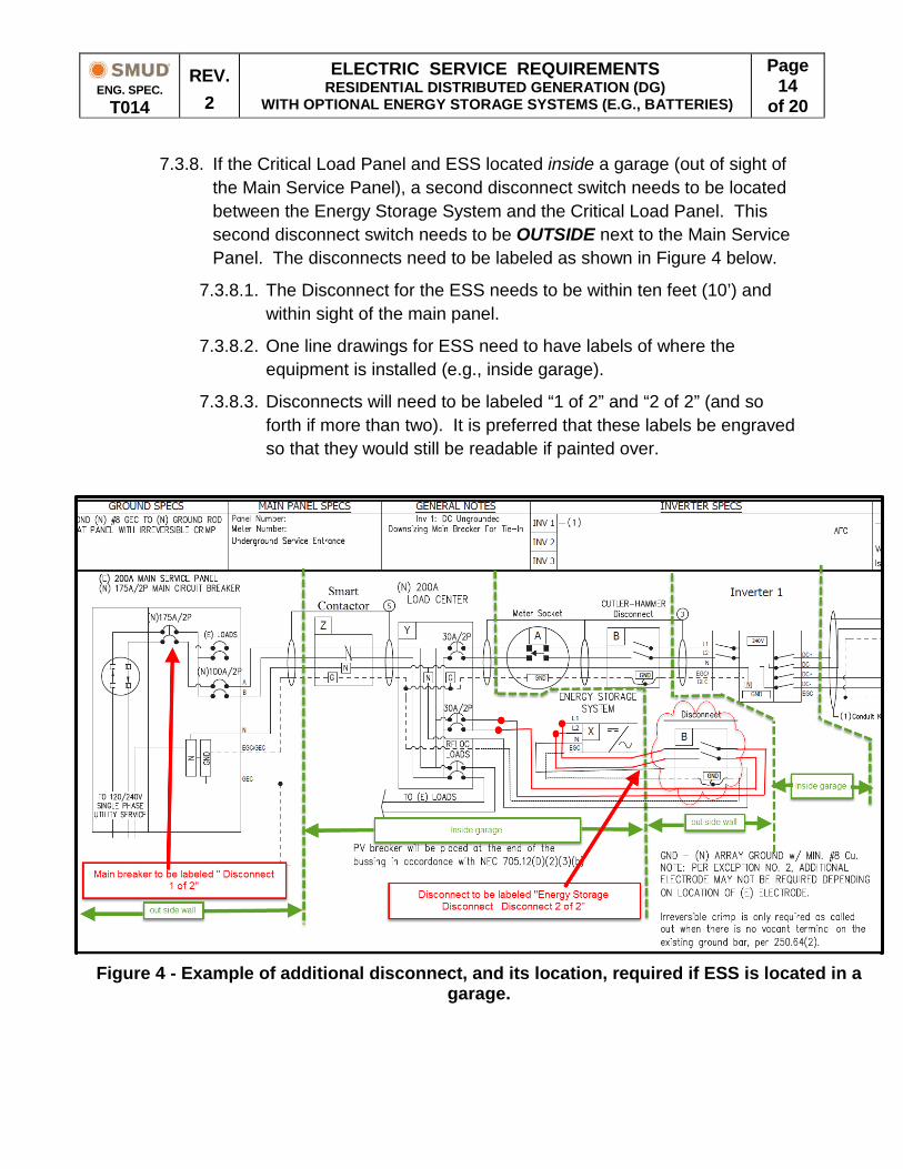
7.3.8. If the Critical Load Panel and ESS located inside a garage (out of sight of the Main Service Panel), a second disconnect switch needs to be located between the Energy Storage System and the Critical Load Panel. This second disconnect switch needs to be OUTSIDE next to the Main Service Panel. The disconnects need to be labeled as shown in Figure 4 below.
7.3.8.1. The Disconnect for the ESS needs to be within ten feet (10’) and within sight of the main panel.
7.3.8.2. One line drawings for ESS need to have labels of where the equipment is installed (e.g., inside garage).
7.3.8.3. Disconnects will need to be labeled “1 of 2” and “2 of 2” (and so forth if more than two). It is preferred that these labels be engraved so that they would still be readable if painted over.
Figure 4 - Example of additional disconnect, and its location, required if ESS is located in a garage.

ENG. SPEC.
T014
REV. 2
ELECTRIC SERVICE REQUIREMENTS RESIDENTIAL DISTRIBUTED GENERATION (DG)
WITH OPTIONAL ENERGY STORAGE SYSTEMS (E.G., BATTERIES)
Page 15
of 20
7.4. Residential – DG and ESS – Option 4: Generation and ESS connected to the DC section of the same inverter.
7.4.1. Provisions in 7.3.1 through 7.3.8 above shall apply.
PanelBreakers
MAINPANEL
Neutral
SMUDServiceMeter
VisibleDisconnect
Device(VDD)
Inverter
+/-
CriticalLoads
EnergyStorage
Equipment
DistributedGenerationEquipment
VisibleDisconnect
Device(VDD)
Figure 5: Residential Distributed Generation with Energy StorageEquipment - Option 4
Generation and ESS directly connected to the Inverter's DC Section
ENG. SPEC.
T014
REV. 2
ELECTRIC SERVICE REQUIREMENTS RESIDENTIAL DISTRIBUTED GENERATION (DG)
WITH OPTIONAL ENERGY STORAGE SYSTEMS (E.G., BATTERIES)
Page 16
of 20
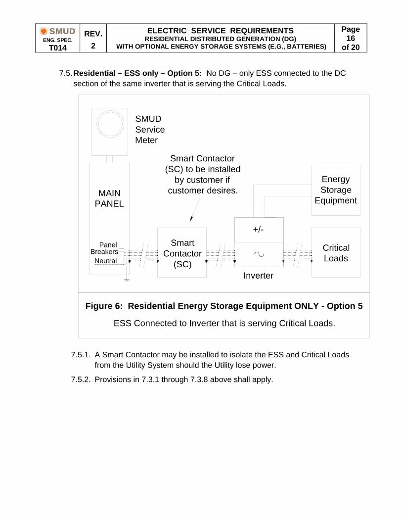
7.5. Residential – ESS only – Option 5: No DG – only ESS connected to the DC section of the same inverter that is serving the Critical Loads.
7.5.1. A Smart Contactor may be installed to isolate the ESS and Critical Loads
from the Utility System should the Utility lose power.
7.5.2. Provisions in 7.3.1 through 7.3.8 above shall apply.
PanelBreakers
MAINPANEL
Neutral
SMUDServiceMeter
SmartContactor
(SC)Inverter
+/-
CriticalLoads
EnergyStorage
Equipment
Figure 6: Residential Energy Storage Equipment ONLY - Option 5
ESS Connected to Inverter that is serving Critical Loads.
Smart Contactor(SC) to be installed
by customer ifcustomer desires.
ENG. SPEC.
T014
REV. 2
ELECTRIC SERVICE REQUIREMENTS RESIDENTIAL DISTRIBUTED GENERATION (DG)
WITH OPTIONAL ENERGY STORAGE SYSTEMS (E.G., BATTERIES)
Page 17
of 20
8. Power Production Metering Requirements - General
8.1. Pursuant to 7.1.2, the Customer shall provide and install the necessary metering socket and cabinet(s) in locations approved by SMUD. A stipend will be provided by SMUD to help offset these costs. SMUD will furnish and install the Power Production Meter at no cost.
8.2. The Power Production Meter socket shall be wired so the output from the Customer's DG Source will be properly measured by the meter. Therefore, the DG shall be wired to the top clips of the PM. All phase conductors, one grounded conductor (neutral), and one grounding conductor (case ground) shall enter the Power Production Meter socket and they shall be labeled to differentiate between SMUD and DG Source.
8.3. The Disconnect Device, Power Production Meter, and the Visible Disconnect Device(s) will be installed in a location readily accessible by SMUD 24 / 7 / 365 and in keeping with SMUD’s metering requirements in T002 and T003.
8.4. A Visible Disconnect Device should be located such that the Power Production Meter remains energized from the Main Panel during Inverter replacements or during maintenance on the DG and/or ESS equipment.
8.5. Under no circumstances shall any metering enclosure be used as a conduit or raceway for any conductors other than those phase conductors being metered and the associated grounded conductor (neutral) and grounding conductor (equipment ground).
8.6. Arrangement and Location - The Power Production Meter shall be located within sight and 10 feet of a Visible Disconnect Device with no other obstruction(s) between them. Where physical limitations prohibit this, alternate arrangements shall be made and approved by SMUD (e.g., installation of additional Visible Disconnect Device(s), labeling as per NEC and Authority Having Jurisdiction, etc.).
8.7. Equipment Protection and Grounding - All related metering enclosures and equipment shall be grounded in compliance with the NEC and the local Authority Having Jurisdiction.
8.8. All equipment shall be approved by a National Recognized Testing Laboratory (NRTL).
8.9. SMUD will be responsible for maintenance, repair, and/or replacement of the Power Production Meter. The Customer will be responsible for the maintenance, repair, and/or replacement of the Power Production Meter socket, Visible Disconnect Device(s), switch(es), and/or Combiner / Sub-Panel.

ENG. SPEC.
T014
REV. 2
ELECTRIC SERVICE REQUIREMENTS RESIDENTIAL DISTRIBUTED GENERATION (DG)
WITH OPTIONAL ENERGY STORAGE SYSTEMS (E.G., BATTERIES)
Page 18
of 20
8.10. After installation, SMUD employees will not energize the DG system. This will be the responsibility of the Customer / Contractor. It will also be the responsibility of the Customer to monitor the production of the DG system.
9. AC Disconnects (where applicable)
The Disconnect Device(s) will isolate all ungrounded (hot) conductors of the generating facility and/or ESS from SMUD’s distribution system. The switch/breaker shall be a gang-operated, load-break rated device.
10. Labeling
Labels shall conform to the current California Electric Code, NEC, and Authority Having Jurisdiction.
Example of panel types *
Eaton/B-Line (catalog #) Residential 011
* or similar from another manufacturer. Please note that Catalog # changes with the number of clips in socket.

ENG. SPEC.
T014
REV. 2
ELECTRIC SERVICE REQUIREMENTS RESIDENTIAL DISTRIBUTED GENERATION (DG)
WITH OPTIONAL ENERGY STORAGE SYSTEMS (E.G., BATTERIES)
Page 19
of 20
Figure 3 - Sample Site Plan (Partial View)

ENG. SPEC.
T014
REV. 2
ELECTRIC SERVICE REQUIREMENTS RESIDENTIAL DISTRIBUTED GENERATION (DG)
WITH OPTIONAL ENERGY STORAGE SYSTEMS (E.G., BATTERIES)
Page 20
of 20
Figure 4 - Sample Cut Sheet PV Connected Between Meter and Main Breaker