research open access a traffic flow-oriented routing ...research open access a traffic flow-oriented...
TRANSCRIPT

Abbasi et al. EURASIP Journal on Wireless Communications and Networking 2014, 2014:121http://jwcn.eurasipjournals.com/content/2014/1/121
RESEARCH Open Access
A traffic flow-oriented routing protocol forVANETsIrshad A Abbasi1, Babar Nazir2*, Aftab Abbasi3, Sardar M Bilal4 and Sajjad A Madani2
Abstract
This paper presents a novel position-based routing protocol for vehicular ad hoc networks (VANETs) to enhancetraffic safety and traffic organization and facilitate driving through a smart transportation system. The protocol isreferred to as the traffic flow-oriented routing (TFOR) protocol for VANETs. It considers a real-time urban scenariowith multi-lane and bi-directional roads. It chooses junction optimally considering vehicular traffic flows toaccomplish robust routing paths and thereby forwarding the data packets. The new junction selection mechanism androuting between the junctions is based on two-hop neighbor information, which increases packet-delivery ratio anddecreases end-to-end delay. We designed, implemented, and compared TFOR against existing routing protocols ofVANETs (greedy-perimeter stateless routing (GPSR), geographic source routing (GSR), and enhanced greedytraffic-aware routing (E-GyTAR)). Simulation outcomes in urban scenarios show that TFOR minimizes averageend-to-end delay and routing overhead by on average 15.3% and 19.5%, respectively, compared to GPSR. Itreduces routing overhead up to 17% compared to GSR. TFOR maximizes packet-delivery ratio on an average of17.5%, 10.7%, and 7.2% compared to GPSR, GSR, and E-GyTAR, respectively.
Keywords: Traffic flow; Traffic organization; Vehicular ad hoc network (VANET); Position-based routing
1. IntroductionRecently, immense increase in the number of automobileson the road made driving difficult and unsafe. Roads areroutinely replete with vehicles, and therefore, safe-separationdistance and sensible speeds do not seemed to be valuedanymore. For instance, according to NHTSA (NationalHighway Traffic Safety Administration) [1] in 2006, therewere an estimated 42,642 traffic-related casualties. The per-centage (2%) of casualties in 2005 was even higher than thatof casualties in 2006. There are some advanced active andpassive vehicle safety-related devices such as airbags, crum-ble zones, and anti-lock brakes invented to reduce causali-ties. The number of casualties in spite of all these latestdevices has remained more than 40,000 per year for the last15 years. Accidents do happen, but sight cannot be lost ofthe concept of road safety. Top car manufacturers and na-tionwide government agencies are determined to design so-lutions that assist drivers in anticipating danger andavoiding bad traffic zones. One such effort is the exploitation
* Correspondence: [email protected] of Computer Science, COMSATS Institute of InformationTechnology (CIIT), Abbotabad 22060, PakistanFull list of author information is available at the end of the article
© 2014 Abbasi et al.; licensee Springer. This is aAttribution License (http://creativecommons.orin any medium, provided the original work is p
of wireless technology, to direct traffic issues, in the form ofwireless access for vehicular environment (WAVE) devotedto the vehicular ad hoc networks (VANETs) [2-4]. Theaim of WAVE is to overcome traffic issues and make driv-ing efficient by giving timely guidance to drivers and vehi-cles that are not available through driver observations andindependent sensors [1,5-7].Vehicular communication is possible through either
vehicle to vehicle (V2V) or vehicle to infrastructure (V2I)or both. The goal of VANETs is to build an intelligenttransportation system (ITS) [8]. It supports a wide varietyof applications including prevention of accidents, trafficflow control mechanisms, information services, real-timealternate route computations, and provision of Internetccess to the vehicles on motion [4,8-13]. Vehicular commu-nication is an offshoot of mobile ad hoc network (MANET)[9,12,14]. VANETs have certain characteristics that changethem from MANETs. In VANETs, >high-speed vehicularnodes have intermittent connectivity and they frequentlychange the network topologies. Physical factors restrictnode movements and network topologies. The movementof vehicles is along roadways, and their mobility is re-strained by traffic policies, such as traffic light signals,
n Open Access article distributed under the terms of the Creative Commonsg/licenses/by/4.0), which permits unrestricted use, distribution, and reproductionroperly credited.
Abbasi et al. EURASIP Journal on Wireless Communications and Networking 2014, 2014:121 Page 2 of 14http://jwcn.eurasipjournals.com/content/2014/1/121
speed constraints, and road/traffic conditions. Powerexpenditure is not a vital concern in vehicular nodes, asvehicles can generate enough power to run the commu-nication devices. In contrast, MANET's nodes are char-acterized by limited storage capacity, restricted batterypower, low processing, and random movements withunpredictable mobility patterns [8,9,12,13].This work realizes the potential of VANETs to enhance
traffic safety and traffic organization and to facilitate driv-ing through a smart transportation system. In this work,we explored routing features of VANETs. We analyzed theprevious routing literatures in VANETs. We have pre-sented their contribution and limitations. By using theunique characteristics of VANETs, we have developed anovel position-based routing protocol called traffic flow-oriented routing (TFOR) protocol for VANET multi-laneroads. It considers the vehicle's position, direction, andspeed to decide the junction and dispatch the datapackets. It consists of two mechanisms: (1) new junctionselection mechanism and (2) routing based on two-hopneighbor information. The new junction selection mech-anism determines the directional and non-directional traf-fic flows based on real-time traffic in city environment.Determination of these flows provides shortest rich-density routing paths, which increase packet-delivery ratioand decrease end-to-end delay. We have also proved thatforwarding, based on two-hop neighbor information, is abetter choice than one-hop neighbor information, whichalso reduces the end-to-end delay and make routing moreefficient. TFOR uses road topology and traffic density forefficient relaying of data in the network. It is useful forboth delay-sensitive (like accident alerts, on-vehicle chat)and delay-tolerant (like infotainment) applications. Themajor contributions of this manuscript are as follows:
1. We provide a brief technical survey to analyze,compare, and present limitations of existingposition-based routing protocols in VANETs.
2. We propose a novel position-based routingalgorithm with new concepts of directional routingand non-directional routing to rout the packetthrough a shortest rich-density city road to increasepacket-delivery ratio and decrease end-to-end delayand routing overhead.
3. We propose a forwarding technique based on two-hopneighbor information and its importance in thereduction of end-to-end delay to obtain optimumperformance.
4. We implement, analyze, and compare the behaviorof our approach with existing approaches(greedy-perimeter stateless routing (GPSR),geographic source routing (GSR), and enhancedgreedy traffic-aware routing (E-GyTAR)) usingVanetMobiSim and Glomosim simulators.
The rest of the paper is organized as follows. Section 2describes the existing routing techniques along with theirlimitations. It also elaborates the motivation of the researchwork. Section 3 illustrates the proposed routing strategy.Analysis of the data and simulation outcomes are presentedin Section 4. Finally, conclusions are presented in Section 5.
2. Related workThe available routing protocols in vehicular communicationnetworks are broadly categorized into topology-based andposition-based routing. The topology-based routing tech-niques can be reactive (on-demand), proactive (table-driven), and hybrid. On-demand routing protocols (e.g.,DSR [15], AODV [16]) maintain only those routing pathsthat are currently in use. While table-driven routing proto-cols (e.g., OLSR [17,18]) maintain all the available paths inthe network topology. The maintenance of routing pathsaffects the performance of protocols in a highly dynamicnetwork [4,8,9,13,14]. In position-based routing protocols,each vehicle contains a GPS receiver or other positioningabilities so that the vehicular nodes can have precise know-ledge of their geological positions, movement directions,and speed. The location of destination node can be foundusing location services (e.g., HLS [19], GLS [20], and RLS[21]). There is no need of path maintenance [4,8,11,22]as each node has to memorize its one-hop neighborsthrough beaconing. These characteristics of position-based approach motivate us to focus on position-basedrouting for dealing the routing-related issues in VANETs.The existing position-based routing protocols are cate-gorized as directional and non-directional. As the namesuggests, the directional routing protocols [10,23,24]focus on the direction of vehicles while routing thepackets towards destination. The non-directional rout-ing protocols [4,8,11,14,22,25] do not focus on the dir-ection of the vehicles while routing. Examples of boththe categories are listed in Table 1.A non-directional protocol is the greedy-perimeter state-
less routing (GPSR) [14] that has been actually designed forhighway scenarios. It works well in a highly dense networkand operates in two phases, viz. greedy phase, and perim-eter phase. In the greedy phase, a node sends the packet toone of its one-hop neighbors that is closest, among all theone-hop neighbors and of course the forwarding node itself,to the destination. If a node is having no one-hop neighborthat is closest to the destination than itself, the greedyphase meets the local maximum. Perimeter phase over-comes the local maximum situation. The perimeter phaseconsists of two modes: namely, the graph planarization andthe right-hand rule. The perimeter phase causes delay inrelaying the packet from the source to the destination [4]and may result in routing loops in the network. In addition,it cannot consider obstacles and, hence, shows poor per-formance in the city environment [4]. Furthermore, the

Table 1 VANET routing protocols
Routingprotocols
Directional Traffic-aware Scenario Traffic datarequired
Carry andforward
Centralized/distributed
Environment Topology-based/position-based routing
Forwardingstrategy
Routing tablebased on one- hopneighbor information
1. GPSR [14] N N Highway No N Distributed Dense Position Greedy Y
Forwarding
2. GSR [4] N N City No N Distributed Sparse Position Greedy Y
Forwarding
3. GPCR [8] N N City No N Distributed Sparse Position Restricted Y
Greedy
Forwarding
4. A-STAR [22] N Y City No Y Distributed Sparse Position Greedy Y
Forwarding
5. GyTAR [25] N Y City Yes Y Distributed Both Position Improve Y
Greedy
Forwarding
6. DGR [24] Y N Highway No Y Distributed Both Position Greedy Y
Forwarding
7. PDGR [10] Y N Highway No Y Distributed Both Position Greedy Y
Forwarding
8. RDGR [10] Y N Highway No Y Distributed Both Position Greedy Y
Forwarding
9. PDVR [23] Y N Highway No Y Distributed Sparse Position Directional Y
Forwarding
10. E-GyTAR [26] Y Y City Yes Y Distributed Both Position Improve Y
Greedy
Forwarding
Abbasiet
al.EURA
SIPJournalon
Wireless
Communications
andNetw
orking2014,2014:121
Page3of
14http://jw
cn.eurasipjournals.com/content/2014/1/121

Abbasi et al. EURASIP Journal on Wireless Communications and Networking 2014, 2014:121 Page 4 of 14http://jwcn.eurasipjournals.com/content/2014/1/121
graph planarization fails in city scenarios and may causepartitioning of the network due to obstacles. Last but notthe least, the fact is that GPSR is not a traffic-aware routingprotocol [22].One of the first attempts to handle the routing issues in
city scenarios was the geographic source routing (GSR) [4]which employs the position-based knowledge with the topo-logical knowledge of the network. It runs Dijkstra's algorithmto locate the shortest route connecting the source and thedestination. GSR computes a sequence of junctions based onthe shortest route from source to destination using a streetmap that packets must have to traverse. It employs greedyforwarding to dispatch the data packets from source to targetnode. The greedy forwarding approach, as already stated, hasthe tendency to stick onto a local maximum. In this, eventu-ality, GSR uses a carry-and-forward approach as a recoverystrategy. This protocol does not consider the number of ve-hicles between the junctions before forwarding packet. End-to-end connection is difficult in case of low traffic densityalong a preselected path [25]. It degrades the performance ofGSR. In addition, it is not a traffic-aware routing protocol.As against GSR, the greedy-perimeter coordinator rout-
ing (GPCR) [8] is a map-independent routing technique. Itincludes restricted greedy forwarding and repair strategy.Restricted greedy forwarding prefers to choose the coordin-ator (the node on a junction) over a non-coordinator nodewhen deciding the next hop, even if the former is not thegeographically nearest node to destination. The routingdecision is, thus, made at the coordinator node that decidesthe street the packet should follow next. The repair strategyovercomes the local optimum problem. It consists of a per-imeter mode without any graph planarization phase. It isassumed that the graph planarization is natural in a cityenvironment. So, there is no need of computing graph pla-narization, because it may cause a partitioning in the net-work. Similar to GSR, the GPCR neglects low traffic densitycase. Furthermore, it is not a traffic-aware routing protocol.The anchor-based street and traffic-aware routing (A-
STAR) is a traffic-aware routing protocol [25], as opposed toGPSR and GSR. From these latter two protocols, A-STARhas two main peculiarities. Firstly, it uses a statically or dy-namically rated map for traffic awareness and uses thesemaps to identify paths having higher number of vehicles.Secondly, A-STAR has a new local recovery technique, con-sidered to be better than those of GSR and GPSR [22], forthe packets got stuck in local maximum. The path selectedby A-STAR on the basis of anchors may not be the shortest,due to which it may have higher end-to-end delay [4,24].Designed for city environment, the greedy traffic-aware
routing protocol (GyTAR) [25] selects the junctionsdynamically as against the static approach of GSR andA-STAR. GyTAR exhibits three mechanisms: (i) a com-pletely decentralized scheme, named the infrastructurefree traffic information system (IFTIS) [21], which estimates
traffic density between the junctions in the urban roads; (ii)a mechanism for dynamic junction selection, i.e., whendeciding the next destination junction, the source vehicle,or an intermediate vehicle in a junction finds the positionof the neighboring junctions using the map, which allo-cates a score to each neighboring junction assuming thecurve metric distance to the destination and the trafficdensity; and the next junction is the one that has highesttraffic density and closest to destination vehicle, (iii) whichapplies an improved greedy forwarding mechanism toforward the packet between the two involved junctions.The wrong junction selection mechanism compels thepacket to get stuck onto local maximum, especially at lowtraffic density or when all the vehicles moved away fromthe destination on the selected street, which is its failure[26]. The directional routing protocols [4,8,11,14,22,25]focus on the direction of the vehicles while routing. Thetechnical detail of these routing protocols is presentedbelow. The main problem with the non-directional routingprotocols is the routing loop formation while routing thepacket, which may cause delay [10]. Sometimes, the packetis sent to a vehicle that is moving away from the destin-ation, resulting in packet loss.Directional greedy routing protocol (DGR) [10] resolves
the issues outlined above by taking into consideration thedirection of the vehicle and assigns higher weight to thevehicle that is moving towards the destination. It uses acarry-and-forward approach when packets get stuck ontoa local maximum and works well in a highway scenario.Predictive directional greedy routing protocol (PDGR) is
an extended version of DGR that employs a predictivecompared to the latter which only takes into account thecurrent neighbors while calculating the weighted score.PDGR determines the weighted score for the packet carrier,its present neighbors, and the possible expected neighborsin the very near future. It decides the next hop based onthese weighted scores. The packet carrier obtains the infor-mation of possible future neighbor based on the two-hopneighbor information. This information is achieved throughperiodical sending of hello messages. The use of a predic-tion mechanism makes the PDGR outperform the DGR interms of end-to-end delay and delivery ratio.The reliable directional greedy routing protocol (RDGR)
[27] minimizes link breaks, improves route reliability, andenhances packet-delivery ratio. In DGR and PDGR, thelikelihood of packet loss increases if the neighbor nodemoving in the direction of destination has higher speed ascompared to source node or intermediate forwarder node.RDGR enhances DGR by introducing the new metric oflink stability. In RDGR, a source node or an intermediateforwarding node chooses the next neighbor node having ahigher speed as well as a stable link.The position-based directional vehicular routing (PDVR)
protocol deals with straight and curvy highway roads [23]. It

Abbasi et al. EURASIP Journal on Wireless Communications and Networking 2014, 2014:121 Page 5 of 14http://jwcn.eurasipjournals.com/content/2014/1/121
selects stable and efficient route for routing packet tothe destination based on two rules. First, the neighborselected for forwarding packet should move in the samedirection as the source or the intermediate packet-forwarding node. Secondly, its direction must be similarto that of the destination. PDVR may not work well in acity environment because of some obstacles. It is not atraffic-aware routing protocol.The DGR, PDGR, and RDGR protocols take into account
only the highway scenarios [27]. The enhanced greedytraffic-aware routing (E-GyTAR) protocol [26] selects arouting path by using an enhanced junction selectionmechanism. In this mechanism, the vehicular node on thecurrent intersection selects the next intersection consider-ing the number of vehicles that are moving in the direc-tion of the destination. If there is completely an oppositeflow of the vehicles and none is moving toward destin-ation, then it cannot select a routing path that may reducepacket-delivery ratio and enhance end-to-end delay.In general, most of the above routing approaches are not
traffic aware. As a result, they forward the packets along thecity street where moving vehicles are absent. In such situ-ation, packets meet local optimum and are discarded. Theseproblems can be solved by having a mechanism that pro-vides timely information about traffic on the city streets.Some of these routing protocols (like A-STAR, E-GyTAR)are traffic aware but they are unable to use real-time vehicu-lar traffic density properly. As a result, these are inefficient inrouting. In between successive junction, most of the aboverouting protocols (GSR, GPSR, A-STAR, etc.) use simplegreedy forwarding. However, simple greedy does not con-sider neighbors' speed and direction. In addition, it uses onlyone-hop neighbor information. Hence, it misses some suit-able candidate vehicles for packet forwarding.
Figure 1 The problem scenario.
We propose a routing protocol that presents a solution tothe aforementioned problems. The protocol accomplishesrobust routes within urban environment. The protocol envi-sioned to work well for different types of VANET appli-cations and ensure user connectivity. These applicationsinclude road-safety services (like traffic flow control mechan-ism, issuing driving alerts like traffic jams, accident warnings,road's condition, etc.) and comfort services (like gas stationlocation, Internet access, music downloading, games, etc.).
3. TFOR3.1. Problem formulationFigure 1 explains the scenario where E-GyTAR does notwork well. The source vehicle S on the current junctionwants to send data packets to the destination vehicle D.E-GyTAR selects the next neighbor junction consideringthe number of vehicles that are moving in the direction ofthe destination. In this scenario, no vehicle is movingtowards the destination. All the vehicles are moving in theopposite direction of the destination but provide enoughconnectivity between S and D. E-GyTAR will not be able toselect the junction J2 that is the closest junction to the des-tination. When the network is sparse, E-GyTAR performswell. However, when the numbers of vehicles are increased,a point comes where there is an adequate number ofvehicles moving in an opposite direction and providingconnectivity. Hence, E-GyTAR cannot find the geographic-ally closest path towards destination. This reduces packet-delivery ratio and enhances end-to-end delay. Therefore,we need a routing protocol that can select the routingpaths/junctions based on directional density and otherwise.To tackle this issue, this paper suggests novel routingprotocol called the traffic flow-oriented routing (TFOR)protocol.

Abbasi et al. EURASIP Journal on Wireless Communications and Networking 2014, 2014:121 Page 6 of 14http://jwcn.eurasipjournals.com/content/2014/1/121
3.2. TFOR protocolTFRO is a junction-based geographical routing protocol,competent to accomplish robust routes, considered to ex-hibit optimal performance in city scenarios. To attain thisgoal, it employs GPS to locate its own position. It uses gridlocation service (GLS) to acquire the position of destin-ation vehicle [20]. Every vehicle contains on-board naviga-tion system that finds out the location of neighboringjunctions and gives valuable city's street information withpreloaded digital maps. It contains two mechanisms, viz.,junction selection mechanism, and routing between junc-tions based on two-hop neighbor information.
3.2.1. The junction selection mechanismUnlike E-GyTAR, which ignores non-directional densitywith respect to destination, TFOR selects the junctions dy-namically considering directional as well as non-directionalflow of traffic density. The probability of occurrence of dir-ectional and non-directional traffic with respect to certaindestinations in urban multi-lane road is equally likely.Therefore, directional and non-directional traffic is equallyimportant for connectivity provision in VANETs. Ignoringa part of traffic density means neglecting connectivity.Compromise on connectivity degrades performance of adhoc networks. The sending vehicular node in a junctionuses a digital map to identify the location of neighboringjunction. Location service makes the position of destinationvehicle available. The sending vehicle after that determinesthe curvemetric distance from each neighbor junction tothe destination vehicle. It uses algorithm 1 to assign a scoreto each neighbor junction. It chooses the junction withmaximum score as a next destination junction. The chosenjunction is the nearest to the destination vehicle. It has alsothe higher traffic density flow.
In algorithm 1, the following equation calculates thescore that determines the next destination junction (N Dj).
score ¼ α� 1−Dp� �þ β� TD ð1Þ
where Dp =Dn /Dc decides the nearness of neighborjunction to the destination point.TD represents the totaltraffic density between the current junction (Cj) and theneighbor or next-candidate junction (N Cj), may be dir-ectional or non-directional. α and β are the weight fac-tors, such that α + β = 1.With equal importance of the two factors, α and β are
both set to the value 0.5. Equation refeq:score suggeststhat the junction that has maximum score is chosen asthe next destination junction. It is also geographicallythe nearest junction to the destination. As revealed inFigure 1, the proposed junction selection mechanism se-lects J2 instead of selecting J3 as the next destinationjunction because of the shortest distance and vehiculartraffic density (directional or non-directional). After-wards, the TFOR junction selection mechanism choosesthe best available shortest path to the destination consid-ering the vehicular density.TFOR uses the infrastructure-free traffic informa-
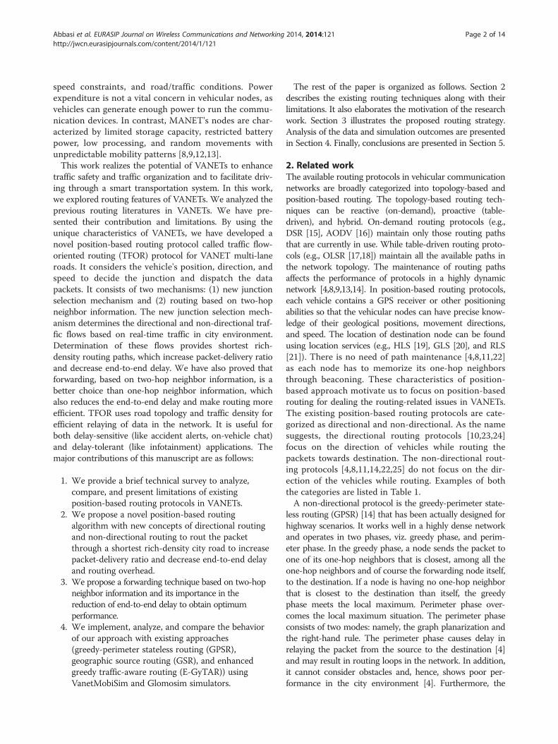
tion system (IFTIS) [20] to calculate traffic densitybetween pairs of junctions. For our scenario, the roadbetween the two junctions is divided into small cells(circles) of fixed size as shown in Figure 2. The vehi-cles belong to the same cell from a group. The cell sizeis equivalent to the vehicle's transmission range that isaround 250 m. The cells superimpose in such a waythat each vehicle belongs to at least one of the cells.Any vehicle that is nearest to the cell's center isnamed as the group head/leader, for the duration is
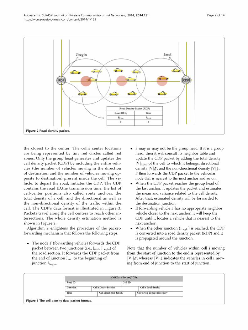
Figure 2 Road density packet.
Abbasi et al. EURASIP Journal on Wireless Communications and Networking 2014, 2014:121 Page 7 of 14http://jwcn.eurasipjournals.com/content/2014/1/121
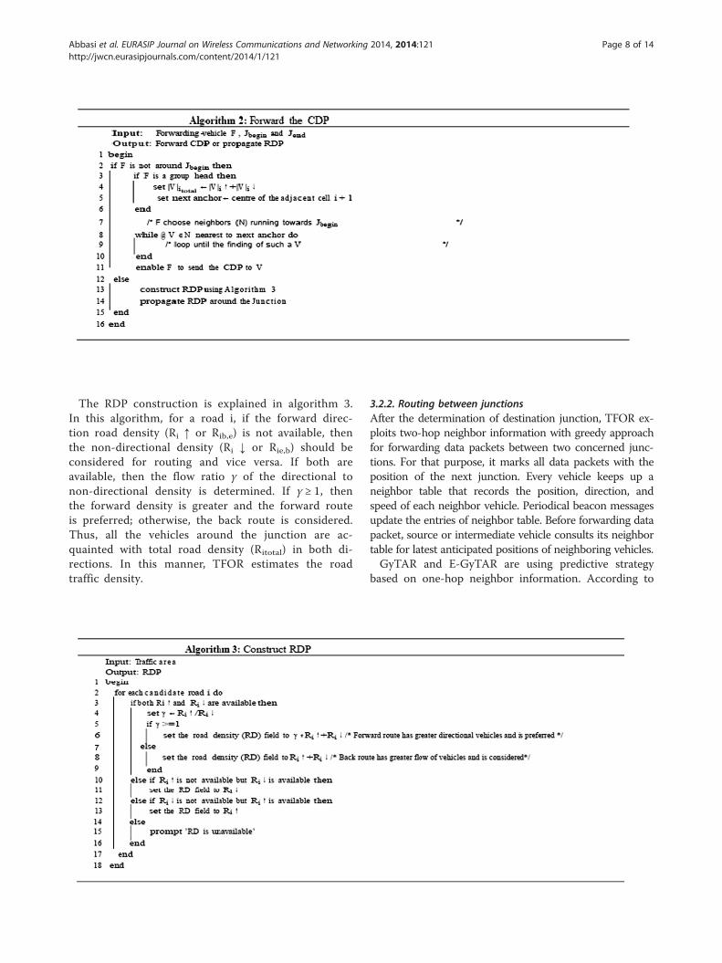
the closest to the center. The cell's center locationsare being represented by tiny red circles called redzones. Only the group head generates and updates thecell density packet (CDP) by including the entire vehi-cles (the number of vehicles moving in the directionof destination and the number of vehicles moving op-posite to destination) present inside the cell. The ve-hicle, to depart the road, initiates the CDP. The CDPcontains the road ID,the transmission time, the list ofcell-center positions also called route anchors, thetotal density of a cell, and the directional as well asthe non-directional density of the traffic within thecell. The CDP's data format is illustrated in Figure 3.Packets travel along the cell centers to reach other in-tersections. The whole density estimation method isshown in Figure 2.Algorithm 2 enlightens the procedure of the packet-
forwarding mechanism that follows the following steps.
� The node F (forwarding vehicle) forwards the CDPpacket between two junctions (i.e., Jend, Jbegin) ofthe road section. It forwards the CDP packet fromthe end of junction Jend to the beginning ofjunction Jbegin.
Figure 3 The cell density data packet format.
� F may or may not be the group head. If it is a grouphead, then it will consult its neighbor table andupdate the CDP packet by adding the total density|V|itotal of the cell to which it belongs, directionaldensity |V|i↑, and the non-directional density |V|i↓.F then forwards the CDP packet to the vehicularnode that is nearest to the next anchor and so on.
� When the CDP packet reaches the group head ofthe last anchor, it updates the packet and estimatesthe mean and variance related to the cell density.After that, estimated density will be forwarded tothe destination junction.
� If forwarding vehicle F has no appropriate neighborvehicle closer to the next anchor, it will keep theCDP until it locates a vehicle that is nearest to thenext anchor.
� When the other junction (Jbegin) is reached, the CDPis converted into a road density packet (RDP) and itis propagated around the junction.
Note that the number of vehicles within cell i movingfrom the start of junction to the end is represented by|V |i↑, whereas |V|i↓ indicates the vehicles in cell i mov-ing from end of junction to the start of junction.
Abbasi et al. EURASIP Journal on Wireless Communications and Networking 2014, 2014:121 Page 8 of 14http://jwcn.eurasipjournals.com/content/2014/1/121
The RDP construction is explained in algorithm 3.In this algorithm, for a road i, if the forward direc-tion road density (Ri ↑ or Rib,e) is not available, thenthe non-directional density (Ri ↓ or Rie,b) should beconsidered for routing and vice versa. If both areavailable, then the flow ratio γ of the directional tonon-directional density is determined. If γ ≥ 1, thenthe forward density is greater and the forward routeis preferred; otherwise, the back route is considered.Thus, all the vehicles around the junction are ac-quainted with total road density (Ritotal) in both di-rections. In this manner, TFOR estimates the roadtraffic density.
3.2.2. Routing between junctionsAfter the determination of destination junction, TFOR ex-ploits two-hop neighbor information with greedy approachfor forwarding data packets between two concerned junc-tions. For that purpose, it marks all data packets with theposition of the next junction. Every vehicle keeps up aneighbor table that records the position, direction, andspeed of each neighbor vehicle. Periodical beacon messagesupdate the entries of neighbor table. Before forwarding datapacket, source or intermediate vehicle consults its neighbortable for latest anticipated positions of neighboring vehicles.GyTAR and E-GyTAR are using predictive strategy
based on one-hop neighbor information. According to

Figure 4 Routing between junctions.
Abbasi et al. EURASIP Journal on Wireless Communications and Networking 2014, 2014:121 Page 9 of 14http://jwcn.eurasipjournals.com/content/2014/1/121
that predictive strategy in Figure 4, the forwarding ve-hicle F sends the packet at time t1 to vehicle A becauseit has greater speed than vehicle B. At time t2, A cannotforward the packet to vehicle C, because it is outside therange of vehicle C. But, If F uses two-hop neighbor in-formation which is achieved by beacon messages, then Fwill dispatch the packet to vehicle C at time t2 through
Car
J1 J2
J4J3
S
Directional flowof vehicles w.r.tDestination D
Non-Directionflow of vehicle
w.r.t destinatio
Ji Junction i
Source Vehicle
Figure 5 Working of TFOR.
neighbor B instead of vehicle A. It is because B is closerto C and C is in turn the closest vehicle to destinationD. This minimizes the end-to-end delay further and di-minishes the number of hop counts as well, whichmakes the routing more efficient. TFOR is based ontwo-hop neighbor information instead of one hop. Everynode maintains two-hop neighbor's table by exchanging
J5
J6 D
als
n D
Destination Vehicle
J8
J7
Two way roadIntersection
Figure 6 The city simulation area.
Abbasi et al. EURASIP Journal on Wireless Communications and Networking 2014, 2014:121 Page 10 of 14http://jwcn.eurasipjournals.com/content/2014/1/121
one-hop neighbor entries through beaconing. The for-warding node or source node looks its two-hop neighbortable and uses greedy forwarding to dispatch the packetthrough its neighbor to the neighbor's neighbor that isclosest to destination. TFOR uses the carry-and-forwardtechnique of [22] to recover from the local optimumsituation.
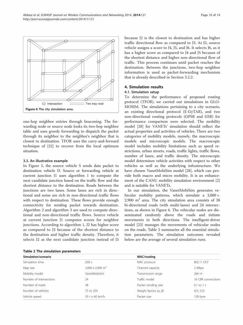
3.3. An illustrative exampleIn Figure 5, the source vehicle S sends data packet todestination vehicle D. Source or forwarding vehicle atcurrent junction J1 uses algorithm 1 to compute thenext candidate junction based on the traffic flow and theshortest distance to the destination. Roads between thejunctions are two lanes. Some lanes are rich in direc-tional and some are rich in non-directional traffic flowswith respect to destination. These flows provide enoughconnectivity for sending packet towards destination.Algorithm 2 and algorithm 3 are used to compute direc-tional and non-directional traffic flows. Source vehicleat current junction J1 computes scores for neighborjunctions. According to algorithm 1, J2 has higher scoreas compared to J3 because of the shortest distance tothe destination and higher traffic density. Therefore, itselects J2 as the next candidate junction instead of J3
Table 2 The simulation parameters
Simulation/scenario
Simulation time 200 s
Map size 3,000 × 2,900 m2
Mobility model VanetMobiSim
Number of intersections 24
Number of roads 38
Number of vehicles 75 to 250
Vehicle speed 35 t o 60 km/h
because J2 is the closest to destination and has highertraffic directional flow as compared to J3. At J2, sourcevehicle assigns a score to J4, J5, and J6. It selects J6, as ithas a higher score as compared to J4 and J5 because ofthe shortest distance and higher non-directional flow oftraffic. This process continues until packet reaches thedestination. Between the junctions, two-hop neighborinformation is used as packet-forwarding mechanismthat is already described in Section 3.2.2.
4. Simulation results4.1. Simulation setupTo determine the performance of proposed routingprotocol (TFOR), we carried out simulations in GLO-MOSIM. The simulations pertaining to a city scenario,an existing directional protocol (E-GyTAR), and twonon-directional routing protocols (GPSR and GSR) forperformance comparison were selected. The mobilitymodel [28] for VANETs' simulation should reflect theactual properties and activities of vehicles. There are twocategories of mobility models, namely, the macroscopicmodels and microscopic models. The macroscopicmodel includes mobility limitations such as speed re-strictions, urban streets, roads, traffic lights, traffic flows,number of lanes, and traffic density. The microscopicmodel determines vehicle activities with respect to othervehicles as well as the underlying infrastructure. Wehave chosen VanetMobiSim model [28], which can pro-vide both macro and micro mobility. It is an enhance-ment of the CANU mobility simulation environment [2]and is suitable for VANETs.In our simulation, the VanetMobiSim generates ve-
hicular mobility patterns, which simulate a 3,000 ×2,900 m2 area. The city simulation area consists of 38bi-directional roads (with multi-lanes) and 24 intersec-tions, as shown in Figure 6. The vehicular nodes are dis-seminated randomly above the roads and initiatemovements in both directions. The intelligent-drivermodel [23] manages the movements of vehicular nodeson the roads. Table 2 summaries all the essential simula-tion parameters. The simulation outcomes revealedbelow are the average of several simulation runs.
MAC/routing
MAC protocol 802.11 DCF
Channel capacity 2 Mbps
Transmission range 266 m
Traffic model 16 CBR connections
Packet sending rate 0.1 to 1 s
Weight factors (α, β) (0.5, 0.5)
Packet size 128 byte
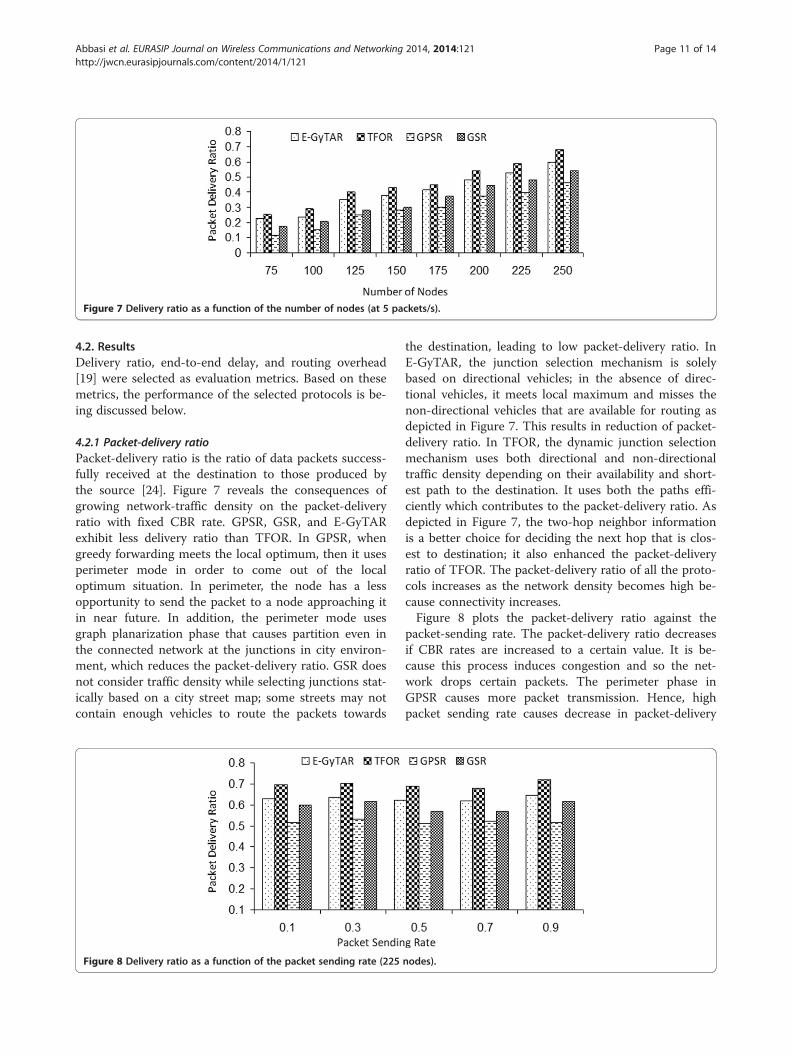
Figure 7 Delivery ratio as a function of the number of nodes (at 5 packets/s).
Abbasi et al. EURASIP Journal on Wireless Communications and Networking 2014, 2014:121 Page 11 of 14http://jwcn.eurasipjournals.com/content/2014/1/121
4.2. ResultsDelivery ratio, end-to-end delay, and routing overhead[19] were selected as evaluation metrics. Based on thesemetrics, the performance of the selected protocols is be-ing discussed below.
4.2.1 Packet-delivery ratioPacket-delivery ratio is the ratio of data packets success-fully received at the destination to those produced bythe source [24]. Figure 7 reveals the consequences ofgrowing network-traffic density on the packet-deliveryratio with fixed CBR rate. GPSR, GSR, and E-GyTARexhibit less delivery ratio than TFOR. In GPSR, whengreedy forwarding meets the local optimum, then it usesperimeter mode in order to come out of the localoptimum situation. In perimeter, the node has a lessopportunity to send the packet to a node approaching itin near future. In addition, the perimeter mode usesgraph planarization phase that causes partition even inthe connected network at the junctions in city environ-ment, which reduces the packet-delivery ratio. GSR doesnot consider traffic density while selecting junctions stat-ically based on a city street map; some streets may notcontain enough vehicles to route the packets towards
Figure 8 Delivery ratio as a function of the packet sending rate (225
the destination, leading to low packet-delivery ratio. InE-GyTAR, the junction selection mechanism is solelybased on directional vehicles; in the absence of direc-tional vehicles, it meets local maximum and misses thenon-directional vehicles that are available for routing asdepicted in Figure 7. This results in reduction of packet-delivery ratio. In TFOR, the dynamic junction selectionmechanism uses both directional and non-directionaltraffic density depending on their availability and short-est path to the destination. It uses both the paths effi-ciently which contributes to the packet-delivery ratio. Asdepicted in Figure 7, the two-hop neighbor informationis a better choice for deciding the next hop that is clos-est to destination; it also enhanced the packet-deliveryratio of TFOR. The packet-delivery ratio of all the proto-cols increases as the network density becomes high be-cause connectivity increases.Figure 8 plots the packet-delivery ratio against the
packet-sending rate. The packet-delivery ratio decreasesif CBR rates are increased to a certain value. It is be-cause this process induces congestion and so the net-work drops certain packets. The perimeter phase inGPSR causes more packet transmission. Hence, highpacket sending rate causes decrease in packet-delivery
nodes).
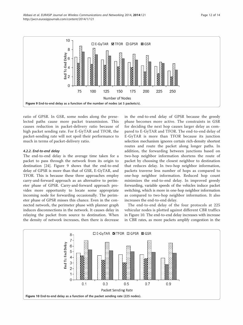
Figure 9 End-to-end delay as a function of the number of nodes (at 5 packets/s).
Abbasi et al. EURASIP Journal on Wireless Communications and Networking 2014, 2014:121 Page 12 of 14http://jwcn.eurasipjournals.com/content/2014/1/121
ratio of GPSR. In GSR, some nodes along the prese-lected paths cause more packet transmission. Thiscauses reduction in packet-delivery ratio because ofhigh packet sending rate. For E-GyTAR and TFOR, thepacket-sending rate will not spoil their performance tomuch in terms of packet-delivery ratio.
4.2.2. End-to-end delayThe end-to-end delay is the average time taken for apacket to pass through the network from its origin todestination [24]. Figure 9 shows that the end-to-enddelay of GPSR is more than that of GSR, E-GyTAR, andTFOR. This is because these three approaches employcarry-and-forward approach as an alternative to perim-eter phase of GPSR. Carry-and-forward approach pro-vides more opportunity to locate some appropriateincoming node for forwarding occasionally. The perim-eter phase of GPSR misses this chance. Even in the con-nected network, the perimeter phase with planner graphinduces disconnections in the network. It causes delay inrelaying the packet from source to destination. Whenthe density of network increases, then there is decrease
Figure 10 End-to-end delay as a function of the packet sending rate
in the end-to-end delay of GPSR because the greedyphase becomes more active. The constraints in GSRfor deciding the next hop causes larger delay as com-pared to E-GyTAR and TFOR. The end-to-end delay ofE-GyTAR is more than TFOR because its junctionselection mechanism ignores certain rich-density shortestroutes and route the packet along longer paths. Inaddition, the forwarding between junctions based ontwo-hop neighbor information shortens the route ofpacket by choosing the closest neighbor to destinationthat reduces delay. In two-hop neighbor information,packets traverse less number of hops as compared toone-hop neighbor information. Reduced hop countminimizes the end-to-end delay. In improved greedyforwarding, variable speeds of the vehicles induce packetswitching, which is more in one-hop neighbor informationas compared to two-hop neighbor information. It alsoincreases the end-to-end delay.The end-to-end delay of the four protocols at 225
vehicular nodes is plotted against different CBR trafficsin Figure 10. The end-to-end delay increases with increasein CBR rates, as more packets amplify congestion in the
(225 nodes).
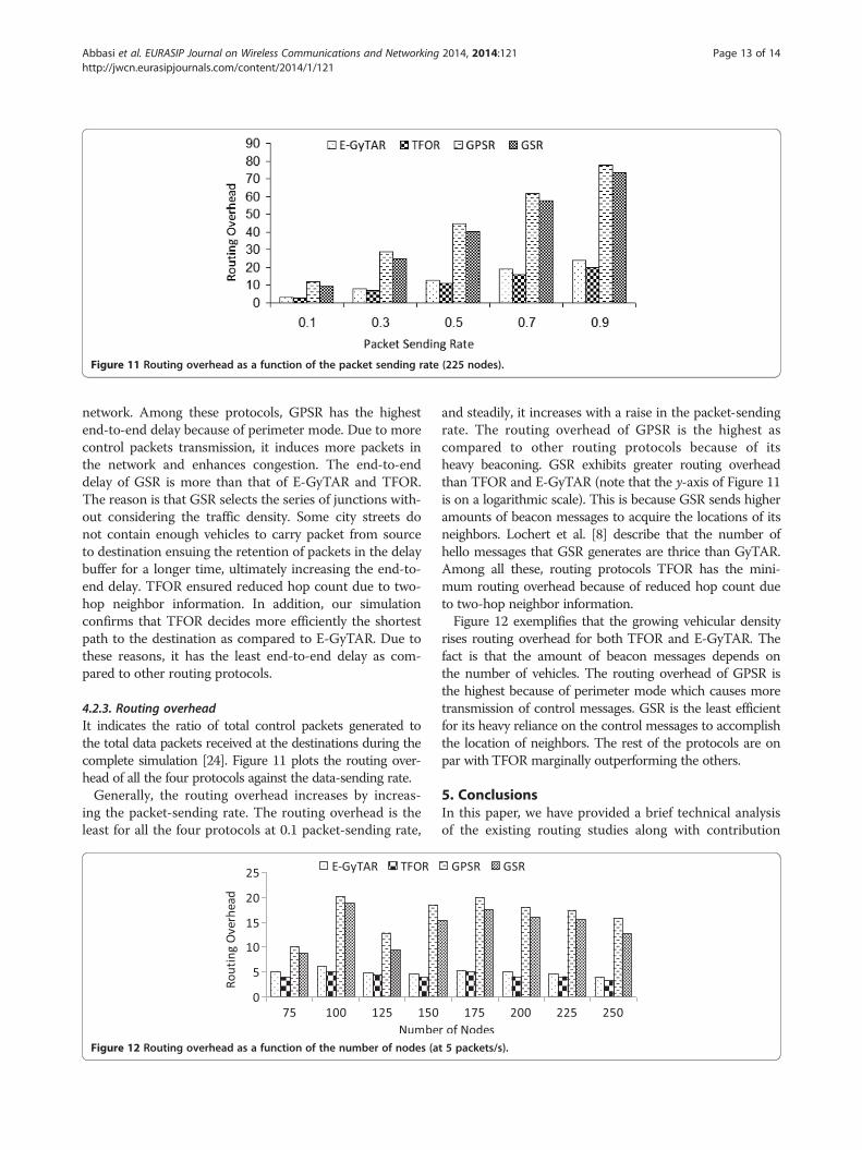
Figure 11 Routing overhead as a function of the packet sending rate (225 nodes).
Abbasi et al. EURASIP Journal on Wireless Communications and Networking 2014, 2014:121 Page 13 of 14http://jwcn.eurasipjournals.com/content/2014/1/121
network. Among these protocols, GPSR has the highestend-to-end delay because of perimeter mode. Due to morecontrol packets transmission, it induces more packets inthe network and enhances congestion. The end-to-enddelay of GSR is more than that of E-GyTAR and TFOR.The reason is that GSR selects the series of junctions with-out considering the traffic density. Some city streets donot contain enough vehicles to carry packet from sourceto destination ensuing the retention of packets in the delaybuffer for a longer time, ultimately increasing the end-to-end delay. TFOR ensured reduced hop count due to two-hop neighbor information. In addition, our simulationconfirms that TFOR decides more efficiently the shortestpath to the destination as compared to E-GyTAR. Due tothese reasons, it has the least end-to-end delay as com-pared to other routing protocols.
4.2.3. Routing overheadIt indicates the ratio of total control packets generated tothe total data packets received at the destinations during thecomplete simulation [24]. Figure 11 plots the routing over-head of all the four protocols against the data-sending rate.Generally, the routing overhead increases by increas-
ing the packet-sending rate. The routing overhead is theleast for all the four protocols at 0.1 packet-sending rate,
Figure 12 Routing overhead as a function of the number of nodes (a
and steadily, it increases with a raise in the packet-sendingrate. The routing overhead of GPSR is the highest ascompared to other routing protocols because of itsheavy beaconing. GSR exhibits greater routing overheadthan TFOR and E-GyTAR (note that the y-axis of Figure 11is on a logarithmic scale). This is because GSR sends higheramounts of beacon messages to acquire the locations of itsneighbors. Lochert et al. [8] describe that the number ofhello messages that GSR generates are thrice than GyTAR.Among all these, routing protocols TFOR has the mini-mum routing overhead because of reduced hop count dueto two-hop neighbor information.Figure 12 exemplifies that the growing vehicular density
rises routing overhead for both TFOR and E-GyTAR. Thefact is that the amount of beacon messages depends onthe number of vehicles. The routing overhead of GPSR isthe highest because of perimeter mode which causes moretransmission of control messages. GSR is the least efficientfor its heavy reliance on the control messages to accomplishthe location of neighbors. The rest of the protocols are onpar with TFOR marginally outperforming the others.
5. ConclusionsIn this paper, we have provided a brief technical analysisof the existing routing studies along with contribution
t 5 packets/s).

Abbasi et al. EURASIP Journal on Wireless Communications and Networking 2014, 2014:121 Page 14 of 14http://jwcn.eurasipjournals.com/content/2014/1/121
and comments. We have also proposed, ‘traffic flow-oriented routing (TFOR) protocol’, a routing protocolfor VANETs. It includes two major phases: first, itselects the next junction optimally, based on direc-tional as well as the non-directional density, andsecondly, it uses two-hop neighbor information forrouting between the junctions. The comparative studyof TFOR with other existing approaches concludes thatour routing protocol performs significantly better thanthe other routing approaches in VANETs. Our simu-lation outcomes confirm that the TFOR outperformsE-GyTAR, GPSR, and GSR. TFOR performed best interms of packet-delivery ratio, with an increase of 7.2%compared to E-GyTAR, more than 16% as compared toGPSR, and 9% as compared to GSR. In case of averageend-to-end delay, TFOR performed best, with delays of15.3% lower than GPSR, 12% lower than GSR, and7.5% lower than E-GyTAR. The proposed improve for-warding mechanism based on two-hop neighbor con-siderably lowers the average routing overhead as wellcompared to existing solutions.In the future, it would be interesting to examine the
behavior of TFOR in the presence of one-way roads. Apossible research direction could be to design a routingtechnique that can work in both environments (city andhighway).
Competing interestsThe authors declare that they have no competing interests.
Author details1Department of Computer Science, King Khalid University (KKU), Abha,Kingdom of Saudi Arabia. 2Department of Computer Science, COMSATSInstitute of Information Technology (CIIT), Abbotabad 22060, Pakistan.3University Malaysia Sarawak (UNIMAS), Kota Samarahan 94300, Malaysia.4Department of Compute and Information Sciences, Universidad Carlos III deMadrid (UC3M), Leganés 28914, Spain.
Received: 4 February 2014 Accepted: 30 June 2014Published: 23 July 2014
References1. H Hartenstein, KP Laberteaux, VANET Vehicular Applications and Inter-Networking
Technologies, 1st edn. (Wiley Online Library, United Kingdom, UK, 2010)2. S Jaap, M Bechler, L Wolf, Evaluation of routing protocols for vehicular ad
hoc networks in city traffic scenarios, in Proceedings of the 5th InternationalConference on Intelligent Transportation Systems Telecommunications (ITST)(Brest, France, 2005)
3. KC Lee, U Lee, M Gerla, Advances in Vehicular Ad-Hoc Networks: Developmentsand Challenges, chapter Survey of Routing Protocols in Vehicular Ad Hoc Networks(IGI Global, Hershey, 2009)
4. YW Lin, YS Chen, SL Lee, Routing protocols in vehicular ad hoc networks: asurvey and future perspectives. J. Inf. Sci. Eng. 26(3), 913–932 (2010)
5. B Nazir, H Hasbullah, Energy balanced clustering in wireless sensor network,International Symposium in Information Technology (ITSim), 2010,pp. 569–574
6. B Nazir, H Hasbullah, Energy efficient and QoS aware routing protocol forClustered Wireless Sensor Network. Comput. Electr. Eng.39(8), 2425–2441 (2013)
7. B Nazir, H Hasbullah, SA Madani, Sleep/wake scheduling scheme forminimizing end-to-end delay in multi-hop wireless sensor networks.EURASIP J. Wirel. Commun. Netw. 92(1), 1–14 (2011)
8. C Lochert, H Hartenstein, J Tian, H Fu¨ßler, D Hermann, M Mauve, A routingstrategy for vehicular ad hoc networks in city environments, in Proceedingsof the Intelligent Vehicles Symposium, 2003. IEEE, 2003, pp. 156–161
9. A Dahiya, RK Chauhan, A comparative study of MANET and VANETenvironment. J. Comput 2(7), 87–91 (2010)
10. J Gong, CZ Xu, J Holle, Predictive directional greedy routing in vehicular adhoc networks, in Distributed Computing Systems Workshops, 2007. ICDCSW'07. 27th International Conference on June 2007
11. B Karp, HT Kung, GPSR: greedy perimeter stateless routing for wirelessnetworks, in Proceedings of the 6th annual international conference on Mobilecomputing and networking, MobiCom '00 (ACM, New York, NY, USA, 2000),pp. 243–254
12. F Li, Y Wang, Routing in vehicular ad hoc networks: a survey. VehicularTechnology Maga- zine, IEEE 2(2), 12–22 (2007)
13. A Rahim, I Ahmad, ZS Khan, M Sher, A Javed, M Shoaib, R Mahmood, Acomparative study of mobile and vehicular adhoc networks. Int. J. RecentTrends Eng. 2(4), 195–197 (2009)
14. GMT Abdalla, MA Abu-Rgheff, SM Senouci, Current trends in vehicular adhoc networks. UbiCC Journal, Special Issue on UbiRoads (2008)
15. DB Johnson, DA Maltz, Dynamic source routing in ad hoc wireless networks,in Mobile Computing (Kluwer Academic Publishers, Alphen aan den Rijn, 1996),pp. 153–181
16. CE Perkins, EM Royer, Ad-hoc on-demand distance vector routing, in MobileComputing Systems and Applications, 1999. Proceedings. WMCSA '99. SecondIEEE Workshop, 1999, pp. 90–100
17. T Clausen, P Jacquet, Optimized Link State Routing Protocol (OLSR), RFC 3626(Internet Engineering Task Force, 2003)
18. AK Gupta, H Sadawarti, AK Verma, Review of various routing protocols forMANETs. Int. J. Inf. Electron. Eng. 1(3), 1–9 (2011)
19. W Kieß, H Fu¨ßler, J Widmer, M Mauve, Hierarchical location service formobile ad-hoc networks: SIGMOBILE Mobile. Comput. Commun. Rev.1(2), 47–58 (2004)
20. J Li, J Jannotti, DSJ Decouto, DR Karger, R Morris, A scalable location servicefor geographic ad hoc routing, in Proceedings of the 6th annual internationalconference on Mobile computing and networking, MobiCom '00 (ACM, NewYork, NY, USA, 2000), pp. 120–130
21. M Kasemann, H Fu¨ßler, H Hartenstein, M Mauve, A reactive location servicefor mobile ad hoc networks, Technical Report, TR-14-2002 (Dept. of ComputerScience, Univ. of Mannheim, 2002)
22. C Lochert, M Mauve, H Fu¨ßler, H Hartenstein, Geographic routing in cityscenarios. SIGMOBILE Mob. Comput. Commun. Rev. 9, 69–72 (2005)
23. D Tian, K Shafiee, VCM Leung, Position-based directional vehicular routing,in Proceeding of the Global Telecommunications Conference, GLOBECOM(IEEE, Hoboken, 2009), pp. 1–6
24. M Jerbi, S-M Senouci, R Meraihi, Y Ghamri-Doudane, An improved vehicularad hoc routing protocol for city environments, in Communications, 2007. ICC'07. IEEE International Conference, 2007, pp. 3972–3979
25. BC Seet, G Liu, BS Lee, CH Foh, KJ Wong, KK Lee, A-STAR, A mobile ad hocrouting strategy for metropolis vehicular communications, in Lecture Notesin Computer Science: NETWORKING 2004, Networking Technologies, Services,and Protocols; Performance of Computer and Communication Networks;Mobile and Wireless Communications, 2004, pp. 989–999
26. S Bilal, SA Madani, IA Khan, Enhanced junction selection mechanism forrouting protocol in VANETs. Arab J. Inf. Technol. 8(4), 422–429 (2011)
27. K Prasanth, K Duraiswamy, K Jayasudha, C Chandrasekar, K Prasanth, KDuraiswamy, K Jayasudha, C Chandrasekar, Improved packet forwardingapproach in vehicular Ad Hoc networks using RDGR algorithm. InternationalJournal of Next- Generation Networks (IJNGN) 2(1), 64–77 (2010)
28. J Harri, F Filali, C Bonnet, M Fiore, VanetMobiSim: generating realisticmobility patterns for VANETs, in Proceedings of the 3rd internationalworkshop on Vehicular ad hoc networks, VANET'06 (ACM, New York, NY, USA,2006), pp. 96–97
doi:10.1186/1687-1499-2014-121Cite this article as: Abbasi et al.: A traffic flow-oriented routing protocolfor VANETs. EURASIP Journal on Wireless Communications and Networking2014 2014:121.