research on the transmission error of swing-rod movable
TRANSCRIPT

Mechanics & Industry 21, 409 (2020)© AFM, EDP Sciences 2020https://doi.org/10.1051/meca/2020036
Mechanics&IndustryAvailable online at:
www.mechanics-industry.org
REGULAR ARTICLE
Research on the transmission error of swing-rod movable teethtransmission systemRui Wei1, Herong Jin2,3,*, and Yali Yi1
1 College of Mechanical Engineering, Yanshan University, Qinhuangdao, PR China2 Key Laboratory of Advanced Forging & Stamping Technology and Science, Ministry of Education of PR China3 Parallel Robot and Mechatronic System Laboratory of Hebei Province, Yanshan University, Qinhuangdao, China
* e-mail: y
Received: 31 August 2019 / Accepted: 24 April 2020
Abstract. Using the two-tooth difference swing-rod movable teeth transmission system satisfying the drivefunction of large optical instruments as the study object, the influence of each component error on systemtransmission error is analysed. Each component error is presented by the vector method, and then it istransformed into equivalent error in the direction of the meshing action line based on the equivalent meshingerror principle. The instantaneous transmission ratio of the system is obtained by the instantaneous velocitycenter method, and the system transmission error model is established. Using numerical analysis, the influence ofeach component error on the system transmission error is obtained. The transmission error test platform is usedto test and analyze the transmission error of the two-tooth difference swing-rod movable teeth transmissionsystem. The research results show that the swing-rod length error and the wave generator eccentric error have agreat influence on the transmission error of the system among the six types of error factors, so they should bestrictly controlled during design, processing and assembly. This study provides a theoretical basis for therational allocation of machining errors and assembling errors of the two-tooth difference swing-rod movableteeth transmission system.
Keywords: two-tooth difference swing-rod movable teeth transmission / equivalent error / instantaneoustransmission ratio / transmission error model / transmission error test platform
1 Introduction
A two-tooth difference swing-rod movable teeth transmis-sion is a type of transmission evolved from a planetarytransmission with small tooth differences, which has theadvantages of a large speed ratio and strong bearingcapacity. It can meet the low-speed, large-torque and high-precision requirements of mechanical transmission systemsfor the aiming and tracking performance of large opticalinstruments such as astronomical telescopes and solarenergy tracking systems [1,2]. There are extensiveprospects of application for this drive in the transmissionfield.
Due to the large number of meshing teeth and theobvious error homogenization effect, research on thetransmission error of planetary transmissions with smalltooth differences has received much attention. Shan et al.[3] established a dynamic transmission precision model ofthe RV transmission system based on the mass concentra-
tion method and the dynamic substructure method, whichtook into account factors such as gear meshing error, gearside clearance and time-varying meshing stiffness. Hanet al. [4] comprehensively considered machining error,assembly error, bearing clearance and other factors andused the Sobol method to analyze the global sensitivity ofthe transmission accuracy of RV cycloidal pin-wheeldrives. Ohta et al. [5] studied the effect of eccentricityon the transmission error of cycloidal gears. Gravagno et al.[6] discussed the influence of the waveform generator shapeon the transmission error of a harmonic reducer. Lin et al.[7] introduced the relationships between parametersconcerning geometry, manufacturing, and precision per-formance for a cycloidal gear reducer and then investigatedthe influence of the tolerances of design parameters on thekinematic error via the theory of gearing. Zhang et al. [8]built a backlash model between eccentric shafts andbearings with the definition of the constraint and functionmethod and studied the effect of the backlash on thetransmission error of the RV reducer. Ren et al. [9]established a Multi-DOF nonlinear dynamic model of acycloidal speed reducer, and then the cycloid disc

Fig. 1. Diagram of two-tooth difference swing-rodmovable teethtransmission.
2 R. Wei et al.: Mechanics & Industry 21, 409 (2020)
rotational displacement and rotational velocity versus timeof different modification clearances were solved by theRunge-kutta numerical method.
In the above studies, the RV reducer and the cycloidalgear reducer can be characterized as a fixed-tooth rigidplanetary transmission with small tooth differences [10].They rely on eccentric mechanisms to achieve the meshingand transmission between cycloidal gears and pins. Theharmonic drive is another type of planetary transmissionwith small tooth differences. The continuous transmissionbetween a flexspline and a circular spline of the harmonicdrive is realized by the deformation of the flexspline[11,12]. The common feature of RV reducers, cycloidalgear reducers and harmonic drive reducers is that there isno moving member between the internal gear and theexternal gear. A two-tooth difference swing-rod movableteeth transmission uses a movable swing-rod and amovable tooth to transfer the rotary motion and powerbetween two co-axes. The movable teeth are radiallymeshed with the ring gear and the wave generator. Thepassive degree of freedom is introduced by the swing-rodmovable tooth to reduce the slip and improve thetransmission precision. However, at the same time, theerror source is increased, which makes the study oftransmission error more complicated. In the previouswork, we have derived the tooth profile equation of swing-rod movable teeth transmission systems and studied theinfluence of tooth profile parameters on the transmissionperformance [13,14]. Due to the existence of machiningerrors, in order to improve the transmission precision ofthe drive, it is necessary to carry out a detailed study onthe transmission error.
In this paper, the single error of each component of thetwo-tooth difference swing-rod movable teeth transmis-sion system is characterized by the vector method. Thesystem transmission error model is established by theprinciple of equivalent meshing error, which reveals theinfluence rule of each component error on the systemtransmission error. The key error factors affecting thesystem transmission error are identified, which provides abasis for reducing the system transmission error in atargeted manner.
2 Transmission principle
The two-tooth difference swing-rod movable teeth trans-mission system consists of a wave generator, a ring gear, aseparator, swing-rods and movable teeth, as shown inFigure 1. r0 is the base circle radius, r is the movable toothradius, l is the length of the swing-rod, and rc is thedistribution circle radius of the swing-rod. The movabletooth and the swing rod are connected by a pin to form arotating pair, and the rotation center is O1. The swing rodand the separator are connected by a pin to form a rotatingpair, and the rotation center is O2. The wave generatormeshes with the movable tooth at M to form a higher pair.Themovable toothmeshes with the ring gear atN to form ahigher pair.
The wave generator is fixed to the input shaft, the ringgear is fixed to the output shaft, and the separator is fixed.When the wave generator rotates at a constant speed, themovable tooth swings around the rotation center O2 underthe thrust of the wave generator. Because of the restrictionof themeshing pair between themovable tooth and the ringgear, the movable tooth drives the ring gear to rotatearound O. At this time, the meshing point N moves alongthe top tooth of the ring gear toward the tooth root. Whenthe meshing point M is at the top of the wave generator,the meshing point N reaches the root of the ring gear. Thisis the lift interval of the movable tooth.
As the wave generator continues to rotate, the movabletooth moves along the wave generator under the backwardthrust of the ring gear. This working range is the returnrange of the movable tooth. Thus, the movable toothcompletes a working cycle. The movable teeth areconnected in parallel and work alternately, which realizesthe speed conversion and power transmission of the two-tooth difference swing-rod movable teeth transmissionsystem at a fixed transmission ratio.
3 Theoretical analysis of meshing error
Errors in the two-tooth difference swing-rod movable teethtransmission system aremainly caused bymachining errorsand assembling errors in the components. According to theequivalent meshing error principle [15], when two compo-nents of a system mesh with each other, the force andmotion are transmitted through the meshing action line(the normal direction of the twomeshing profiles), and onlythe error on the meshing action line will have an impact onthe movement between the two components. Therefore, itis necessary to study the equivalent error of eachcomponent error on the meshing action line.
3.1 The equivalent error of the wave generator error
The error of the wave generator mainly includes eccentricerror and tooth profile error. Taking a movable tooth as theresearch object, the equivalent error calculation diagram ofthe wave generator is shown in Figure 2.
The eccentric error of the wave generator comes fromthe deviation of the actual rotation center of the wavegenerator from the theoretical rotation center. lHg is the
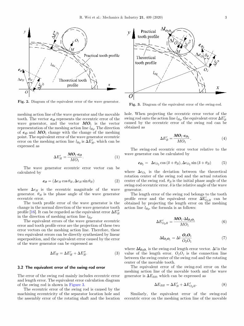
Fig. 2. Diagram of the equivalent error of the wave generator.Fig. 3. Diagram of the equivalent error of the swing-rod.
R. Wei et al.: Mechanics & Industry 21, 409 (2020) 3
meshing action line of the wave generator and the movabletooth. The vector eO represents the eccentric error of thewave generator, and the vector MO1 is the vectorrepresentation of the meshing action line lHg. The directionof eO and MO1 change with the change of the meshingpoint. The equivalent error of the wave generator eccentricerror on the meshing action line lHg is DE 0
H , which can beexpressed as
DE 0H ¼ MO1⋅eO
MO1: ð1Þ
The wave generator eccentric error vector can becalculated by
eO ¼ DeH cos uH ;DeH sin uHð Þ ð2Þwhere DeH is the eccentric magnitude of the wavegenerator. uH is the phase angle of the wave generatoreccentric error.
The tooth profile error of the wave generator is thechange in the normal direction of the wave generator toothprofile [16]. It can be regarded as the equivalent error DE 00
Hin the direction of meshing action line lHg.
The equivalent errors of the wave generator eccentricerror and tooth profile error are the projection of these twoerror vectors on the meshing action line. Therefore, thesetwo equivalent errors can be directly synthesized by linearsuperposition, and the equivalent error caused by the errorof the wave generator can be expressed as
DEH ¼ DE 0H þ DE 00
H : ð3Þ
3.2 The equivalent error of the swing-rod error
The error of the swing rod mainly includes eccentric errorand length error. The equivalent error calculation diagramof the swing rod is shown in Figure 3.
The eccentric error of the swing rod is caused by themachining eccentricity of the separator location hole andthe assembly error of the rotating shaft and the location
hole. When projecting the eccentric error vector of theswing rod onto the action line lHg, the equivalent error DE 0
Bcaused by the eccentric error of the swing rod can beobtained as
DE 0B ¼ MO1⋅eO2
MO1: ð4Þ
The swing-rod eccentric error vector relative to thewave generator can be calculated by
eO2¼ DeO2
cos ðdþ uBÞ;DeO2sin ðdþ uBÞ
� � ð5Þ
where DeO2is the deviation between the theoretical
rotation center of the swing rod and the actual rotationcenter of the swing rod. uB is the initial phase angle of theswing-rod eccentric error. d is the relative angle of the wavegenerator.
The length error of the swing rod belongs to the toothprofile error and the equivalent error DE 0
O2Hcan be
obtained by projecting the length error on the meshingaction line lHg, the formula is as follows:
DE 0O2H
¼ MO1⋅DlO2O1
MO1ð6Þ
DlO2O1¼ Dl⋅
O2O1
O2O1ð7Þ
where DlO2O1is the swing-rod length error vector. Dl is the
value of the length error. O2O1 is the connection linebetween the swing center of the swing rod and the rotatingcenter of the movable tooth.
The equivalent error of the swing-rod error on themeshing action line of the movable tooth and the wavegenerator is DEBH, which can be expressed as
DEBH ¼ DE 0B þ DE 0
O2H: ð8Þ
Similarly, the equivalent error of the swing-rodeccentric error on the meshing action line of the movable

Fig. 4. Diagram of ring gear equivalent tooth profile error.(a) Radial error and cumulative pitch error of tooth i. (b) Theerror in the direction of the movable tooth radius.
4 R. Wei et al.: Mechanics & Industry 21, 409 (2020)
tooth and the ring gear is DE 00B, which can be expressed as
DE 00B ¼ O1N⋅e 0O2
O1Nð9Þ
e 0O2¼ DeO2
sin ðhþ uBÞ;DeO2cos ðhþ uBÞ
� � ð10Þ
where e 0O2is the eccentric error vector of the swing rod
relative to the ring gear. h is the relative angle of the ringgear. O1N represents the meshing action line of the ringgear and the movable tooth.
When the ring gear meshes with the movable tooth, theequivalent error of the swing-rod length error on themeshing action line of the movable tooth and the ring gearis DE 0
O2K, which can be expressed as
DE 0O2K
¼ O1N⋅DlO2O1
O1N: ð11Þ
Therefore, the equivalent error DEBK caused by theswing-rod error on the meshing action line of the movabletooth and the ring gear can be expressed as
DEBK ¼ DE 00B þ DE 0
O2K: ð12Þ
3.3 The equivalent error of the ring gear error
The error of the ring gear mainly comes from eccentric errorand tooth profile error of the ring gear, as shown inFigure 4a. Assume that Ris is the radial error of the i thtooth profile of the ring gear. lKg is the meshing action lineof the movable tooth and the ring gear. Projecting Ris ontothe meshing action line lKg, the equivalent error eRis
can beobtained as follows:
eRis¼ Ris sin g1 ð13Þ
where g1 is the pressure angle of the movable tooth and thering gear.
Pis is the cumulative pitch error of the i th tooth of thering gear. Calculating its projection onto the action line lKggives an equivalent error ePis
as follows:
ePis¼ Pis cos g1 ð14Þ
ed is the tooth profile error of the ring gear in the radialdirection of the movable tooth, which can be regarded asthe equivalent error in the direction of meshing action linelKg, as shown in Figure 4b.
Taking the above three error factors into consideration,the equivalent error DE 00
K caused by the tooth profile errorof the ring gear can be expressed as
DE 00K ¼ eRis
þ ePisþ ed ð15Þ
The ring gear eccentric error and the wave generatoreccentric error belong to the same type of error, and thesolution method is the same as that of the wave generator.Therefore, the equivalent error DE 0
K of the ring gear
eccentric error can be obtained as follows:
DE 0K ¼ O1N⋅e 0O
O1Nð16Þ
e 0O ¼ ðDeK cos uK;DeK sin uKÞ ð17Þwhere DeK is the eccentric magnitude of the ring gear. uK isthe initial phase angle of the ring gear eccentric error.
Therefore, the equivalent error DEK caused by thetooth profile error and eccentric error of the ring gear can beexpressed as
DEK ¼ DE 0K þ DE 00
K: ð18Þ
4 System transmission error
The equivalent error of two components in meshing issynthesized from the equivalent error of each component inthe meshing pair, that is, the equivalent error in themeshing of the wave generator and the movable tooth canbe obtained through the synthesis of the equivalent errorDEH (caused by the wave generator error) and theequivalent error DEBH (caused by the swing-rod error).Similarly, the equivalent error of the meshing between themovable tooth and the ring gear can be synthesized by theequivalent error DEK and the equivalent error DEBK.

Fig. 5. Diagram of transmission ratio calculation.
R. Wei et al.: Mechanics & Industry 21, 409 (2020) 5
The equivalent error is linear error, which needs to beconverted into angular error by instantaneous transmissionratio. The instantaneous transmission ratio of the two-tooth difference swing-rod movable teeth transmissionsystem can be obtained by the instantaneous velocitycenter method.
According to the Kennedy-Aronhold theorem. Therelative instantaneous centre of velocity between the wavegenerator and the swing-rod is PH, which is theintersection point of the common normal line lHg andthe connection line OO2. The relative instantaneouscentre of velocity between the swing-rod and the ring gearis PK, which is the intersection point of the commonnormal line lKg and the connection line OO2. OR and OTare the vertical distances from the rotation centerO to thecommon normal lines lHg and lKg, respectively. O2U andO2V are the vertical distance between the swing-rodrotation center O2 and the common normal lines lHg andlKg, as shown in Figure 5.
The distance from the wave generator rotation centerOto the meshing normal line lHg is calculated by the followingequation:
OR ¼ OO1 sin ð∠OO1MÞ ð19Þwhere ∠OO1M ¼ arccos OO1⋅MO1
OO1⋅MO1.
The distance OT from the ring gear rotation center Oto the meshing action line lKg is
OT ¼ ON sin ð∠ONO1Þ ð20Þwhere ∠ONO1 ¼ arccos NO⋅NO1
NO⋅NO1.
The distance O2U from the swing-rod rotation centerO2 to the meshing action line lHg is
O2U ¼ O1O2 sin ð∠MO1O2Þ ð21Þwhere ∠MO1O2 ¼ arccos O1O2⋅O1M
O1O2⋅O1M.
The distance O2V from the swing-rod rotation centerO2 to the meshing action line lKg is
O2V ¼ O1O2 sin ð∠NO1O2Þ ð22Þwhere ∠NO1O2 ¼ arccos O1N⋅O1O2
O1N⋅O1O2.
The two-tooth difference swing-rod movable teethtransmission system achieves the purpose of decelerationthrough two changes in the speed. The first speed changeoccurs when the wave generator meshes with the movabletooth, and the second speed change occurs when themovable tooth meshes with the ring gear. As shown inFigure 5, the instantaneous transmission ratio iH at the firstspeed change is
iH ¼ O2PH
OPH¼ O2U
OR: ð23Þ
The instantaneous transmission ratio iK at the secondspeed change is
iK ¼ OPK
O2PK¼ OT
O2V: ð24Þ
The movable tooth is a follower when the wavegenerator and the movable tooth are engaged. And thering gear is a follower when the movable tooth is meshedwith the ring gear. If the angle of the follower is taken as theoutput when the two components are engaged, the angularerror of the meshing of the movable tooth with the wavegenerator is
DuHB ¼ DEH
OR⋅1
iHþ DEBH
O2U¼ DEHþDEBH
O2U: ð25Þ
The angular error of the meshing of the ring gear withthe movable tooth is
DuKB ¼ DEBK
O2V⋅1
iKþ DEK
OT¼ DEBK þ DEK
OT: ð26Þ
Since the two-tooth difference swing-rod movable teethtransmission system is a two-stage reducer, its transmis-sion error is obtained by superimposing the equivalenterror DuHB and the equivalent error DuKB on the systemoutput components. When the ring gear is the outputcomponent, the system transmission error Du is
Du ¼ DuHB
iKþ DuKB: ð27Þ
By substituting equations (24)–(26) into equation (27),the transmission error model of a two-tooth differenceswing-rod movable teeth transmission system can beobtained.
5 Transmission error calculation and analysis
The geometric parameters of the components in the two-tooth difference swing-rod movable teeth transmissionsystem are selected as follows: swing coefficient A=0.18

Fig. 6. The curves of transmission errors. (a) The influence curve of wave generator tooth profile error. (b) The influence curve of wavegenerator eccentricity error. (c) The influence curve of swing-rod eccentric error. (d) The influence curve of swing-rod length error.(e) The influence curve of ring gear eccentricity error. (f) The influence curve of ring gear tooth profile error. (g) The influence curve ofcomprehensive error.
6 R. Wei et al.: Mechanics & Industry 21, 409 (2020)
[17], the length of the swing rod l=12mm, the distributioncircle radius of the swing rod rc=48mm, the base circleradius r0 = 40mm, the movable tooth radius r=6mm, andthe transmission ratio i=6.
Based on the theoretical analysis results, the influenceof a single error of each component on the systemtransmission error is analyzed, which can be divided intothe following six situations: (1) only a wave generator toothprofile error; (2) only a wave generator eccentric error; (3)only a swing-rod eccentric error; (4) only a swing-rodlength error; (5) only a ring gear eccentric error; (6) only aring gear tooth profile error. To reveal the influence weight
of the above six types of errors on the system transmissionerror, the single variable unified principle is adopted.Considering the technical requirements of the aiming andtracking device of the solar tracking system, each errorvalue is taken as 0.006mm, and the initial phase angle is setas p/3. According to equation (27), when the error valuesare the same, the transmission error variation caused byeach single error of the two-tooth difference swing-rodmovable teeth transmission system is analyzed. Thetransmission error influence curves of the system underthe action of a single error shown in Figures 6a–f areobtained. Considering the above six types of errors
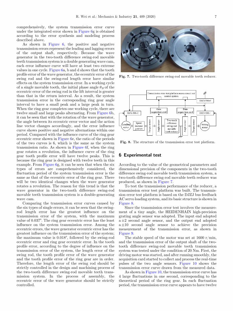
Fig. 7. Two-tooth difference swing-rod movable teeth reducer.
Fig. 8. The structure of the transmission error test platform.
R. Wei et al.: Mechanics & Industry 21, 409 (2020) 7
comprehensively, the system transmission error curveunder the integrated error shown in Figure 6g is obtainedaccording to the error synthesis and modeling processdescribed above.
As shown in Figure 6, the positive and negativetransmission errors represent the leading and lagging errorsof the output shaft, respectively. Because the wavegenerator in the two-tooth difference swing-rod movableteeth transmission system is a double generating wave cam,each error influence curve will have at least two extremevalues in one cycle. Figure 6a, b and d shows that the toothprofile error of the wave generator, the eccentric error of theswing rod and the swing-rod length error have similareffects on the system transmission error. In a working cycleof a single movable tooth, the initial phase angle uB of theeccentric error of the swing rod in the lift interval is greaterthan that in the return interval. As a result, the systemtransmission error in the corresponding ring gear angleinterval to have a small peak and a large peak in turn.When the ring gear completes one working cycle, there aretwelve small and large peaks alternating. From Figure 6b,it can be seen that with the rotation of the wave generator,the angle between its eccentric error vector and the actionline vector changes accordingly, and the error influencecurve shows positive and negative alternations within oneperiod. Compared with the influence curve of the ring geareccentric error shown in Figure 6e, the ratio of the periodsof the two curves is 6, which is the same as the systemtransmission ratio. As shown in Figure 6f, when the ringgear rotates a revolution, the influence curve of the ringgear tooth profile error will have twelve peaks. This isbecause the ring gear is designed with twelve teeth in thisexample. From Figure 6g, it can be seen that when the sixtypes of errors are comprehensively considered, thefluctuation period of the system transmission error is thesame as that of the eccentric error of the ring gear. Therewill be two identical changes when the wave generatorrotates a revolution. The reason for this trend is that thewave generator in the two-tooth difference swing-rodmovable teeth transmission system is a double-generatingwave cam.
Comparing the transmission error curves caused bythe six types of single errors, it can be seen that the swing-rod length error has the greatest influence on thetransmission error of the system, with the maximumvalue of 0.037°. The ring gear eccentric error has the leastinfluence on the system transmission error. Among theeccentric errors, the wave generator eccentric error has thegreatest influence on the transmission error of the system;the maximum value is 0.018°, followed by the swing-rodeccentric error and ring gear eccentric error. In the toothprofile error, according to the degree of influence on thetransmission error of the system, the length error of theswing rod, the tooth profile error of the wave generatorand the tooth profile error of the ring gear are in order.Therefore, the length error of the swing rod should bestrictly controlled in the design and machining process ofthe two-tooth difference swing-rod movable teeth trans-mission system. In the process of assembly, theeccentric error of the wave generator should be strictlycontrolled.
6 Experimental test
According to the value of the geometrical parameters anddimensional precision of the components in the two-toothdifference swing-rod movable teeth transmission system, atwo-tooth difference swing-rod movable teeth reducer wasproduced, as shown in Figure 7.
To test the transmission performance of the reducer, atransmission error test platform was built. The transmis-sion error test platform is based on the DJZJ bus feedbackAC servo loading system, and its basic structure is shown inFigure 8.
Since the transmission error test involves the measure-ment of a tiny angle, the HEIDENHAIN high-precisiongrating angle sensor was adopted. The input end adopteda±2 second angle sensor, and the output end adopteda±10 second angle sensor to achieve the precisionmeasurement of the transmission error, as shown inFigure 9.
The stable speed of the motor was set at 1600 r/min,and the transmission error of the output shaft of the two-tooth difference swing-rod movable teeth transmissionsystem was tested under the condition of 20 Nm. First, thedriving motor was started, and after running smoothly, theacquisition card started to collect and process the real-timepulses of the two angle sensors. Figure 10 shows thetransmission error curve drawn from the measured data.
As shown in Figure 10, the transmission error curve has4 large fluctuations in one second, corresponding to thetheoretical period of the ring gear. In each fluctuationperiod, the transmission error curve appears to have twelve

Fig. 10. The test curve of transmission error.
Fig. 9. The transmission error test platform.
8 R. Wei et al.: Mechanics & Industry 21, 409 (2020)
peaks, corresponding to the number of ring gear designteeth being 12. Comparing the comprehensive error curvesof Figure 10 and Figure 6g, the maximum differencebetween the theoretical data and the experimental data is0.02°, which verifies the accuracy of the transmission errorcalculation model.
7 Conclusion
In this paper, based on the structural characteristicsof the two-tooth difference swing-rod movable teethtransmission and taking the errors of the wave generator,the swing-rod and the ring gear into consideration, theformula for calculating the meshing pair error of the two-tooth difference swing-rod movable teeth transmissionsystem was derived, and the transmission error model ofthe system was established. Then, the influence curve ofthe system transmission error was obtained bynumerical analysis, and the transmission error of thetwo-tooth difference swing-rod movable teeth transmis-sion system was tested. The results of the study are asfollows:
– The transmission error of the two-tooth difference swing-rod movable teeth transmission system is mainly causedby the eccentric error and tooth profile error of eachcomponent. These two types of errors will cause periodicfluctuations of the system transmission error. Amongthem, the influence curves of the tooth profile error of thewave generator, the eccentric error and the length errorof the swing rod on the system transmission error aresimilar. The ratio of the error fluctuation period causedby the ring gear eccentric error to the error fluctuationperiod caused by the eccentric error of the wave generatoris 6, which is the same as the system transmission ratio.
–
When the influence of six types of errors is taken intoconsideration, the fluctuation period of the systemtransmission error is the same as that of the eccentricerror of the ring gear. Because the two-tooth differenceswing-rod movable teeth transmission system uses thedouble-generating wave cam as the wave generator, thetransmission error curve will have two identical changetendencies when the wave generator rotates a revolution.–
Among the tooth profile errors, the swing-rod lengtherror has the greatest influence on the system transmis-sion error, followed by the wave generator tooth profileerror and the ring gear tooth profile error. Among theeccentric errors, the eccentric error of the wave generatorhas the greatest influence on the system transmissionerror, while the eccentric error of the swing-rod and ringgear has little influence.The research results provide a reference for theprecision control of the machining errors and assemblingerrors of each component of the two-tooth difference swing-rod movable teeth transmission system. This researchmethod offers reference significance for the error analysis ofmovable tooth transmission systems.
Nomenclature
A
Swing coefficient [�] eO Eccentric error vector of the wave generator[mm]
e 0O Eccentric error vector of the ring gear [mm] eO2Eccentric error vector of the swing-rod relative tothe wave generator [mm]
e 0O2
Eccentric error vector of the swing rod relative tothe ring gear [mm]ePis
Equivalent error of Pis on the meshing action linelKg [mm]eRis
Equivalent error of Ris on the meshing action linelKg [mm]ed
Tooth profile error of the ring gear in the radialdirection of the movable tooth [mm]i
Transmission ratio of the two-tooth differenceswing-rod movable teeth transmission system [–]iH
Instantaneous transmission ratio at the first speedchange [–]iK
Instantaneous transmission ratio at the secondspeed change [–]l
Length of the swing-rod [mm] lHg Meshing action line of the wave generator and themovable tooth [�]
lKg Meshing action line of the movable tooth and thering gear [�]

R. Wei et al.: Mechanics & Industry 21, 409 (2020) 9
Pis
Cumulative pitch error of the i th tooth of the ringgear [mm]r
Movable tooth radius [mm] r0 Base circle radius of the wave generator [mm] rc Distribution circle radius of the swing rod [mm] Ris Radial error of the i th tooth profile of the ringgear [mm]
DeH Eccentric magnitude of the wave generator[mm]
DeK Eccentric magnitude of the ring gear [mm] DeO2Deviation between the theoretical rotation centerof the swing rod and the actual rotation center ofthe swing rod [mm]
DE 0B
Equivalent error caused by the swing rodeccentric error on the meshing action line lHg[mm]
DE 00B
Equivalent error of the swing-rod eccentric erroron the meshing action line of the movable toothand the ring gear [mm]
DEBH
Equivalent error of the swing-rod error on themeshing action line of the movable tooth and thewave generator [mm]DEBK
Equivalent error caused by the swing-rod error onthe meshing action line of the movable tooth andthe ring gear [mm]DEH
Equivalent error caused by the wave generatorerror on the meshing action line lHg [mm]DE 0H
Equivalent error of the wave generator eccentricerror on the meshing action line lHg [mm]
DE 00H
Equivalent error of the wave generator toothprofile error in the direction of meshing action linelHg [mm]DEK
Equivalent error caused by the tooth profile errorand eccentric error of the ring gear [mm]DE 0K
Equivalent error of the ring gear eccentric error onthe meshing action line lKg [mm]
DE 00K
Equivalent error caused by the tooth profile errorof the ring gear [mm]DE 0O2H
Equivalent error of the swing rod length error onthe meshing action line lHg [mm]
DE 0O2K
Equivalent error of the swing-rod length error onthe meshing action line of the movable tooth andthe ring gear [mm]
Dl
The value of the swing-rod length error [mm] DlO2O1The swing-rod length error vector [mm]
Du System transmission error [°] DuHB Angular error of the meshing of the movable toothwith the wave generator [°]
DuKB Angular error of the meshing of the ring gear withthe movable tooth [°]
uB Initial phase angle of the swing-rod eccentricerror [°]
uH Phase angle of the wave generator eccentricerror [°]
uK Initial phase angle of the ring gear eccentric error[°]
d Relative angle of the wave generator [°] h Relative angle of the ring gear [°]g1
Pressure angle of the movable tooth and the ringgear [°]The author(s) disclosed receipt of the following financial supportfor the research, authorship, and/or publication of this article:This work has been supported by the National Nature ScienceFoundation of China (Grant No. 51605416).
References
[1] A.A. Lubkov, Y.A. Popov, Modern ground-basedsolar telescopes and requirements for their automationsystems, Optoelectr. Instr. Data Process. 55, 93–106(2019)
[2] S. Skouri, A. Ben Haj Ali, S. Bouadila, M. Ben Salah,S. Ben Nasrallah, Design and construction of suntracking systems for solar parabolic concentrator dis-placement, Renew. Sustain. Energy Rev. 60, 1419–1429(2016)
[3] L.J. Shan, Y.T. Liu,W.D. He, Analysis of nonlinear dynamicaccuracy on RV transmission system, Advanced MaterialsResearch. 510, 529–535 (2012)
[4] L.S. Han, F. Guo, Global sensitivity analysis of transmis-sion accuracy for RV-type cycloid-pin drive, Journal ofMechanical Science and Technology. 30, 1225–1231(2016)
[5] H. Ohta, A. Yamakawa, Y. Katayama, Effects of eccentricityon transmission errors of trochoidal gears, Journal ofTribology. 134, 97–104 (2012)
[6] F. Gravagno, V.H. Mucino, E. Pennestri, Influence of wavegenerator profile on the pure kinematic error and centrodesof harmonic drive, Mechanism and Machine Theory. 104,100–117 (2016)
[7] K.S. Lin, K.Y. Chan, J.J. Lee, Kinematic error analysis andtolerance allocation of cycloidal gear reducers, Mechanismand Machine Theory. 124, 73–91 (2018)
[8] Y.H. Zhang, Z. Chen, W.D. He, Virtual prototypesimulation and transmission error analysis for RV reducer,Applied Mechanics and Materials. 789-790, 226–230(2015)
[9] Z.Y. Ren, S.M. Mao, W.C. Guo, Z. Guo, Toothmodification and dynamic performance of the cycloidaldrive, Mechanical Systems and Signal Processing. 85,857–866 (2017)
[10] S.J. Tsai, L.C. Chang, C.H. Huang, Design of cycloidplanetary gear drives with tooth number difference of two,Forschung im Ingenieurwesen. 81, 325–336 (2017)
[11] D. León, N. Arzola, A. Tovar, Statistical analysis of theinfluence of tooth geometry in the performance of a harmonicdrive, Journal of the Brazilian Society ofMechanical Sciencesand Engineering. 37, 723–735 (2015)
[12] D.H. Ma, J.N.Wu, T. Liu, S.Z. Yan, Deformation analysis ofthe flexspline of harmonic drive gears considering the drivingspeed effect using laser sensors, Science China(TechnologicalSciences). 60, 1175–1187 (2017)
[13] Y.L. Yi, H.R. Jin, Y.F. Gao, L. He, Study on swing movableteeth drive with external generating wave mode, Mechanika.25, 240–247 (2019)

10 R. Wei et al.: Mechanics & Industry 21, 409 (2020)
[14] Y.L. Yi, C. Shao, H.R. Jin, Pressure angle analysis of adouble generating wave swing rod movable tooth drive,China Mechanical Engineering. 27, 2160–2165 (2016)(in Chinese)
[15] X.Q. Lei, Q. Meng, W.S. Ma, K.L. Yang, Research ontransmission errors of closed loop gear transmission systems,China Mechanical Engineering. 28, 675–682 (2017)(in Chinese)
[16] Q.G. Li, Q.S. Han, B.Y. Peng, H.J. Wang, Research ofcontour error compensation control for X-C non-circulargrinding in polar coordinates, Instrumentation. 1, 29–37 (2014)
[17] R. Wei, H.R. Jin, Y.L. Yi, Design and analysis of gear profileof two-tooth difference swing-rod movable teeth transmis-sion system, in Proceedings of the 12th InternationalConference on Intelligent Robotics and Applications(ICIRA), Shenyang, China, August 8-11, 2019
Cite this article as: R. Wei, H. Jin, Y. Yi, Research on the transmission error of swing-rod movable teeth transmission system,Mechanics & Industry 21, 409 (2020)