research on sn contrast ratio for sgii-pw laser system jianqiang zhu, guang xu, xiaoping ouyang and...
TRANSCRIPT
Research on SN Research on SN contrast ratio for SGII-contrast ratio for SGII-
PW laser System PW laser System Jianqiang Zhu, Guang Xu, Xiaoping
Ouyang and Xinglong Xie 23/4/18
2
Outline
Introduction
SG-II PW laser facility and recent achievements
SN contrast ratio study in SG-II PW laser facility
Programs of ultra short lasers in NLPLP
Conclusion
3
Outline
Introduction
SG-II PW laser facility and recent achievements
SN contrast ratio study in SG-II PW laser facility
Programs of ultra short lasers in NLPLP
Conclusion
4
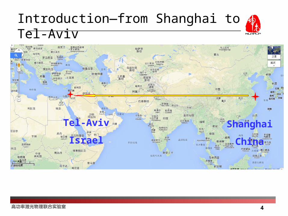
Introduction—from Shanghai to Tel-Aviv
Shanghai
China
Tel-Aviv
Israel

5
Development of Lab
YEARYEAR
SG-I facility was accepted with 1.6kJ/1ns(1ω)
the NLHP Lab was founded
SG-II multi-functional high-power laser system(the 9th beam) was accepted with 5kJ/3ns(1ω)
SG-II facility was began to launch
SG-II facility was accepted with 6kJ/1ns(1ω
SG-II-up facility will be completed and reach 24KJ/3ns(3ω)) and the 9th beam will reach 1KJ/(1-10)ps(1ω).
SG-II-up facility was officially launched
2001
2006
2007
2014
1987
1995
1986
6
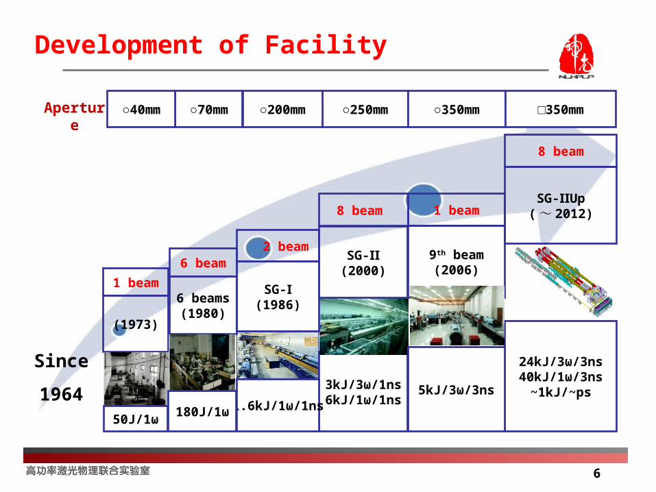
Development of Facility
Aperture ○250mm○200mm ○350mm □350mm
3kJ/3ω/1ns6kJ/1ω/1ns
SG-Ⅱ(2000)
8 beam
(1973)
1 beam SG-Ⅰ(1986)
2 beam
24kJ/3ω/3ns40kJ/1ω/3ns
~1kJ/~ps
8 beam
SG- UpⅡ( ~ 2012)
6 beams(1980)
6 beam
1.6kJ/1ω/1ns5kJ/3ω/3ns
1 beam
9th beam(2006)
180J/1ω50J/1ω
○70mm○40mm
Since
1964

7
About SG-II Facility
8 Pulsed Laser BeamsEnergy 6KJ/1W/1ns 2KJ/3W/1ns
1KJ/1W/130ps
8 Pulsed Laser BeamsEnergy 6KJ/1W/1ns 2KJ/3W/1ns
1KJ/1W/130ps
8
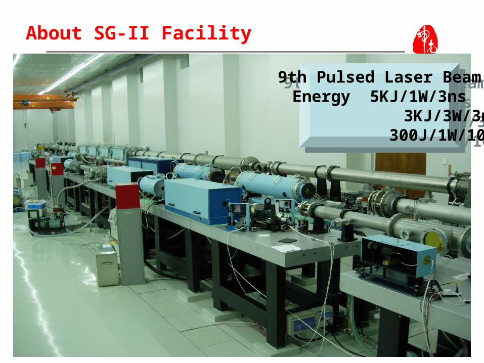
About SG-II Facility
9th Pulsed Laser BeamEnergy 5KJ/1W/3ns 3KJ/3W/3ns
300J/1W/100ps
9th Pulsed Laser BeamEnergy 5KJ/1W/3ns 3KJ/3W/3ns
300J/1W/100ps

9
About SG-II Facility
ICF Target ChamberX-ray Target Chamber
9th Laser Beams InjectionPrecision 20μm(rms)
ICF Target ChamberX-ray Target Chamber
9th Laser Beams InjectionPrecision 20μm(rms)

10
About SG-II Facility
No.9 Laser Beam injectingICF Target Chamber andX-ray Target Chamber
have 3 styles.
No.9 Laser Beam injectingICF Target Chamber andX-ray Target Chamber
have 3 styles.

11
SG-II Facility Experiment Function
Neutron production 4×10 9
1000 times target compression
Physical experiments :Black cavity radiation physics
Implosion physics
Hydrodynamic instability
Radiation opacity
SG-II has achieved about 4000
shots since 2000, the success rate
more than 80%
Radiation-driven shock wave
Temperature and density plasma physics
Production and application of X-Ray
12
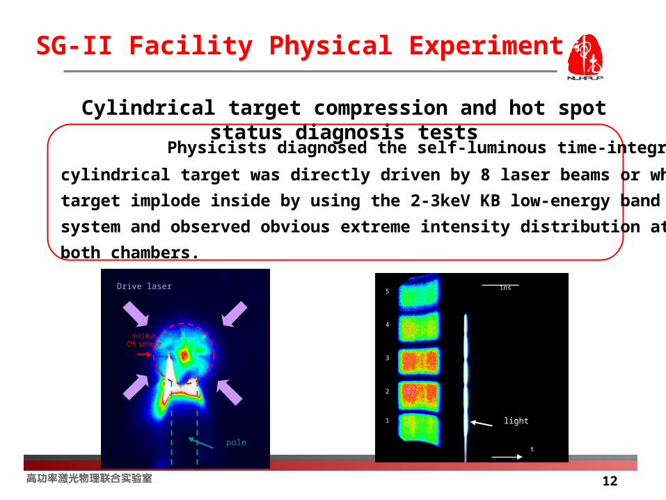
SG-II Facility Physical Experiment
pole
Drive laser
310mCH sphere
tt
11
22
33
44
55
light
1ns1ns
Cylindrical target compression and hot spot status diagnosis tests
Physicists diagnosed the self-luminous time-integration image when the
cylindrical target was directly driven by 8 laser beams or when the spherical
target implode inside by using the 2-3keV KB low-energy band of KB imaging
system and observed obvious extreme intensity distribution at the center of
both chambers.
13
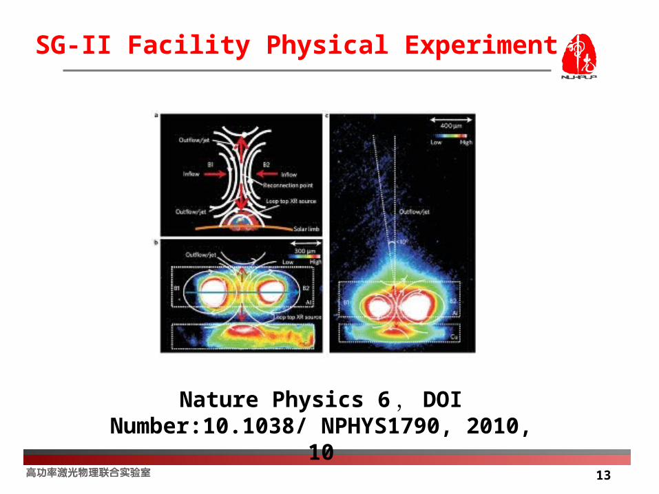
SG-II Facility Physical Experiment
Nature Physics 6 , DOI Number:10.1038/ NPHYS1790, 2010, 10

14
SG-II Facility Physical Experiment
Under the support of “Joint research on high energy density physics
with Japan and South Korea”, the three parties successfully carried out
collision-free shock wave experiments on SG device on September 16, Ⅱ
which provides important evidence on the cause of collision-free shock
wave phenomena in astrophysics. The output laser quality has reached
international advanced level.
Experimental results of collision-free shock wave
Results published on “Plasma Physics and Controlled Fusion”(2008, 50, 124057) and was invited to the 8th Pacific Rim International Conference on Laser and Optoelectronics report.
The experimental results were included in the “Large scientific facilities of the Chinese Academy of Sciences” (2008-2009 )

15
Summary
——SG-II facility is an important platform for inertial confinement fusion
(ICF) research and national physical researches, which also represents
the general technology achievement in high power laser physics.
——SG-II facility have 9 laser beams, provide:
8 laser beams: 750J/beam/1w/1ns, 250J/beam/3w/1ns,
120J/beam/1w/130ps
No.9 laser beam: 5000J/beam/1w/3ns, 3000J/beam/3w/3ns
500J/beam/1w/300ps
10J/beam/1w or 3w/30ps
——SG-II up facility will be completed and reach 24KJ/3ns(3ω)) , and the
9th beam will reach 1KJ/(1-10)ps(1ω).

16
Outline
Introduction
SG-II PW laser facility and recent achievements
SN contrast ratio study in SG-II PW laser facility
Programs of ultra short lasers in NLPLP
Conclusion

17
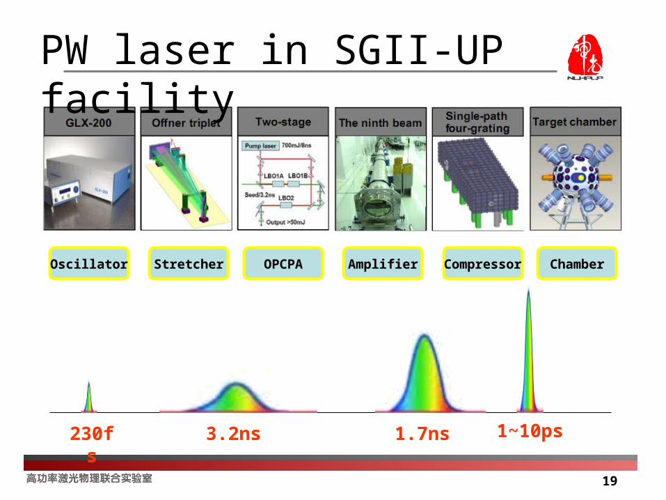
PW laser in SGII-UP facility
8 beams
Energy: 3000J/beam at 351nm
Pulse width: 3ns
1 beams
Energy: 1000J at 1053nm
Pulse width: 1~10ps
Intensity: 1020W/cm2
Contrast: 106~108
Ps pulse
Ns pulses
18
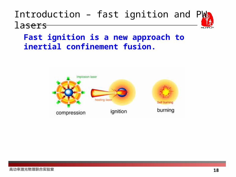
Introduction – fast ignition and PW lasers
Fast ignition is a new approach to inertial confinement fusion.
19
Oscillator Stretcher OPCPA Amplifier Compressor Chamber
230fs 3.2ns 1~10ps1.7ns
PW laser in SGII-UP facility

20
Recent achievements in SG-II PW laser facility
Pulse energy : 380J
Time width: 5ps
Beam size: 105*290mm ( elliptical )
Focal spot: 1.3DL(2013 年实验数据 :E50%=5.1DL)
Grating size: 300*340mm( 1740g/mm)
21
Outline
Introduction
SG-II PW laser facility and recent achievements
SN contrast ratio study in SG-II PW laser facilitySN contrast ratio simulations for PW laser pulses
SN contrast ratio test for SG-II PW laser
SN contrast ratio improvement for SG-II PW laser
Programs of ultra short lasers in NLPLP
Conclusion

22
Ul tra short pul se contrast(Si mul ati on)
1. 00E- 12
1. 00E- 09
1. 00E- 06
1. 00E- 03
1. 00E+00
- 1000 - 900 - 800 - 700 - 600 - 500 - 400 - 300 - 200 - 100 0 100
Ti me (ps)
Inte
nsit
y (P
W)
Pre-pulse from oscillator
Pedestal from stretcher
Satellite from non-linear chirped
SN contrast ratio Simulations for PW laser pulses
Different noise before main pulse

23
Pulse contrast test
Schematic of cross-correlation
Time delay
SHG
Cross-correlation
Detector
Measurement for repetition pulse, time delay is caused by
movement of delaying mirror pairs.
Measurement for single shot pulse, time delay is caused by
tilting of two wide beams.
Phase plane
Tim
e delay
55º
24
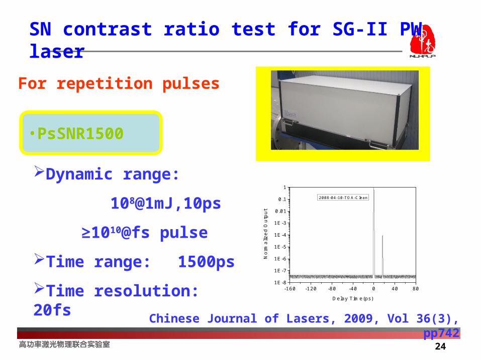
•PsSNR1500
For repetition pulses
Dynamic range:
108@1mJ,10ps
≥1010@fs pulse
Time range: 1500ps
Time resolution: 20fs
Chinese Journal of Lasers, 2009, Vol 36(3), pp742
-160 -120 -80 -40 0 40 801E-8
1E-7
1E-6
1E-5
1E-4
1E-3
0.01
0.1
1
No
rma
lize
d O
utp
ut
Delay Time(ps)
2008-04-10-TOA-Clean
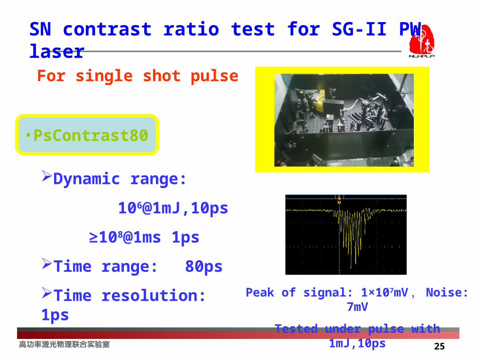
SN contrast ratio test for SG-II PW laser
25
SN contrast ratio test for SG-II PW laser
•PsContrast80
For single shot pulse
Dynamic range:
106@1mJ,10ps
≥108@1ms 1ps
Time range: 80ps
Time resolution: 1ps Peak of signal: 1×10⁷mV , Noise: 7mV
Tested under pulse with 1mJ,10ps

26
Far field
Pulse width
Sampling energy
Pulse contrast
Dia
gnos
tics
for
SG
IIN
inth
Bea
m
Large aperture calorimeterParabolic mirror in target chambe
Sampling mirror
Down-collimator
G1
G2
G4
G3
Lens1
Lens2
BS1BS2
BS3
T=1%
T=2%
Compressor
8:1
1700J/1.7ns
Final test for SG-II PW laser

27
SN contrast ratio test for SG-II PW laser
Compressed Pulse Diagnostics
PW laser: 100J, 5ps
Test on PW laser:

28
1 SN contrast ratio control in pulse stretcher
2 SN contrast ratio control in OPCPA pre-amplifier
3 Spectrum shape for chirped laser pulse
4 Controlling smoothness of the optics surface
5 Plasma mirror
SN contrast ratio improvement for SG-II PW laser

29
R1
R2Grating
SN contrast ratio control in pulse stretcher
1) Pulse contrast can be improved by decreasing tolerance of mirror’s curvature in stretcher.
2) Pulse contrast can be improved by decreasing tolerance of mirror’s tilt in stretcher
Offner Stretcher
Pulse contrast by
curvature error
(ΔS=R1/2-R2)
Pulse contrast
by tilt error

30
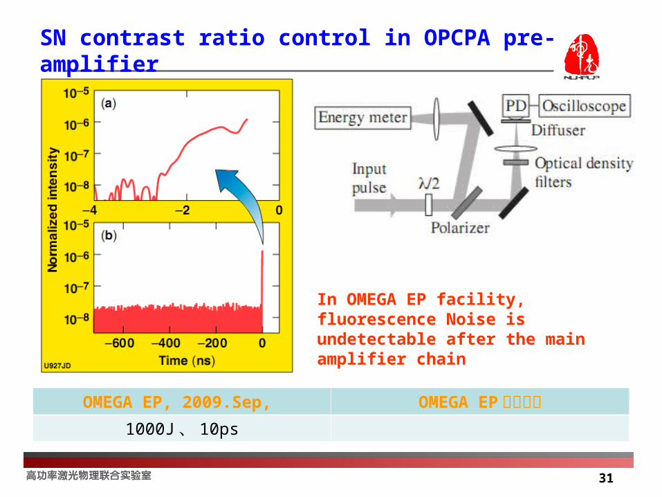
SN contrast ratio control in OPCPA pre-amplifier
1) Noise from parameter fluorescence is avoid by non-collinear(1-3°) mode in OPCPA.
2) pulse contrast ratio can be improved by time lag between pump laser and signal. In this method, noise before main pulse of signal will not be amplified.
Chirped pulse
Pump pulse
Non-collinear mode in OPCPA Time lag between pump laser
and signal
31
OMEGA EP, 2009.Sep, OMEGA EP测试方案1000J 、 10ps
SN contrast ratio control in OPCPA pre-amplifier
In OMEGA EP facility, fluorescence Noise is undetectable after the main amplifier chain
32
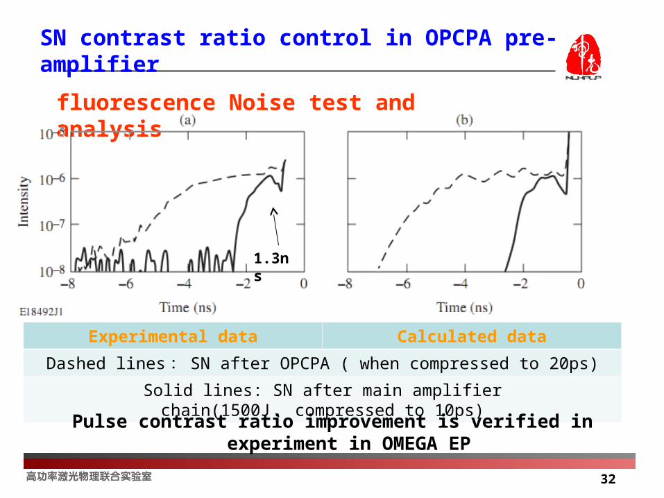
SN contrast ratio control in OPCPA pre-amplifier
fluorescence Noise test and analysis
Experimental data Calculated data
Dashed lines : SN after OPCPA ( when compressed to 20ps)
Solid lines: SN after main amplifier chain(1500J 、 compressed to 10ps)
1.3ns
Pulse contrast ratio improvement is verified in experiment in OMEGA EP

33
SN contrast ratio control in OPCPA pre-amplifier
Time delay between pump pulse and chirped pulse in OPCPA
OPCPA front-end prototype High-energy OMEGA EP pulse
~100uJ 、 20ps 500J 、 10ps
34
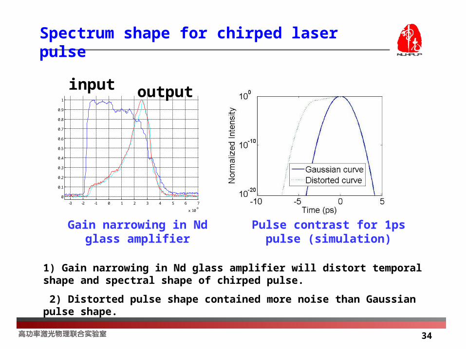
Spectrum shape for chirped laser pulse
-3 -2 -1 0 1 2 3 4 5 6 7
x 10-9
0
0.1
0.2
0.3
0.4
0.5
0.6
0.7
0.8
0.9
1
Gain narrowing in Nd glass amplifier
Pulse contrast for 1ps pulse (simulation)
1) Gain narrowing in Nd glass amplifier will distort temporal shape and spectral shape of chirped pulse.
2) Distorted pulse shape contained more noise than Gaussian pulse shape.
input output
35
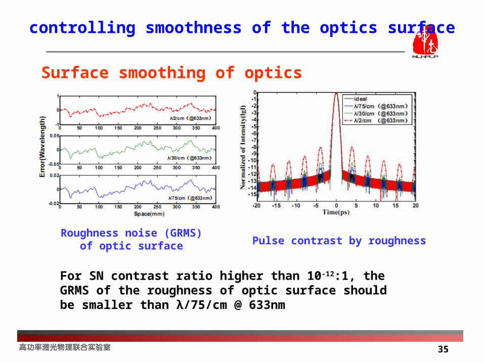
controlling smoothness of the optics surface
Surface smoothing of optics
Roughness noise (GRMS) of optic surface Pulse contrast by roughness
For SN contrast ratio higher than 10-12:1, the GRMS of the roughness of optic surface should be smaller than λ/75/cm @ 633nm

36
Plasma mirror
PM1
PM2
Parabolic mirror 1
Parabolic mirror 2
PsContrast80
Ps pulse10mJ, 12ps f=30mm
f=30mm
I=1016W/cm2
φ30mm
Schematic of double PMs experiment
Plasma mirror is considered in our PW laser. It is designed as the following figure. And it will be tested under ps pulse laser in the future.

37
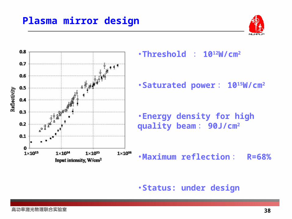
Plasma mirror design
Pulse contrast improved by
Double plasma mirrors (DPM)
Opitcs Letters Vol.32(3), pp310
Contrast is improved 104 in France (2007) and in German (2013) .
38
•Threshold : 1012W/cm2
•Saturated power : 1015W/cm2
•Energy density for high quality beam : 90J/cm2
•Maximum reflection : R=68%
•Status: under design
Plasma mirror design
39
Outline
Introduction
SG-II PW laser facility and recent achievements
SN contrast ratio study in SG-II PW laser facility
Programs of ultra short lasers in NLPLP
Conclusion
40
Project of 10PW 808nm Laser
10PW (30fs/300J) 808nm laser project has been supported
Goals:
In the following 2 or 3 years – 10 PW facility provided for fundamental physical experiments
Programs of ultra short lasers in NLPLP
41
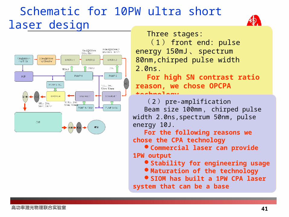
Schematic for 10PW ultra short laser design
Three stages:( 1 ) front end: pulse energy 150mJ 、
spectrum 80nm,chirped pulse width 2.0ns.
For high SN contrast ratio reason, we chose OPCPA technology
( 2 ) pre-amplificationBeam size 100mm , chirped pulse width
2.0ns,spectrum 50nm, pulse energy 10J.For the following reasons we chose the
CPA technologyCommercial laser can provide 1PW
outputStability for engineering usageMaturation of the technologySIOM has built a 1PW CPA laser system
that can be a base

42
( 3 ) Energy amplification for 10PW outputBeam size 200mm , LBO crystalPUMP source: width 3.0ns , 1500J 527nmOUTPUT: pulse energy 300J , spectrum 45-50nmCompressed pulse: 20-30 fs.
In the design of the main amplification, we chose OPCPA technology for the following reasons:
OPCPA technology bears high SN contrast pulsesAnd also can decease the uncompressed noise by
nonlinear process.When goes to large beam size, CPA technology has low
efficiency and noise will be increased by the transverse oscillation.
For engineering reason, we can use the SG-II and the Ninth Beam as the PUMP source for OPCPA design.
Schematic for 10PW ultra short laser design

43
750mJ
0.5GW/cm2200J
0.8GW/cm2
1500J1.5GW/cm2
OPCPA-I CPA-IICPA-III OPCPA-IV
150mJ 1-2J 20J 300J
1.5J( 50%) 400J(50%)
3000J(50%)
CPAPre-OPCPA OPCPA
Energy fluence design for 10PW laser

44
Φ6mm,150mJ
1.5m
1.5m 5m
14m
Φ100mm,40J
PUMP
Φ50mm,10J
Φ110mm,270J
3ns,flat
F=1.3m 2.6m
S=1.5m 2m
F=0.73m 6.1m
S=0.8m 1m
Φ55mm,65J
3ns,平顶
Φ8mm,0.75J
3ns,平顶
OPCPA1.5m*4m
展宽器
1.5m*3.5m
CPA
Layout of 10PW laser amplification chain
The pump beams of SG-II laser

45
7m
4.5m
4.5m
2m
Φ230mm,300J
Φ260mm,1500J,2ns (from 9th beam)
Φ 400mm,300J
F=2m 4.25m
S=1.7 5.8m
F=1.6m 3.7m
S=1.5m 4.2m
46
Outline
Introduction
SG-II PW laser facility and recent achievements
SN contrast ratio study in SG-II PW laser facility
Programs of ultra short lasers in NLPLP
Conclusion

47
Conclusion
In conclusion
SG-II PW laser and recent progress are introduced.
Factors that affect the SN contrast ratio of SG-II PW laser are discussed.
We have measured the SN contrast ratio for the output of SG-II PW laser at 100J@5ps.
Program of ultra short and ultra high power 10 PW laser has been designed based on SG-II and SG-Ninth beam, our goal is in three to five years the laser can be provided for fundamental physical experiments.

48
Thank You for Your Attention !