research on deep-hole drilling quality of high- strength
TRANSCRIPT
Research on Deep-hole Drilling Quality of High-strength Steel With Slender Gun DrillJiabin Liang
Key Laboratory of Fundamental Science for Advanced Machining, Beijing Institute of Technology,Beijing100081, ChinaLi Jiao
Key Laboratory of Fundamental Science for Advanced Machining, Beijing Institute of Technology,Beijing100081, ChinaPei Yan ( [email protected] )
Beijing Institute of TechnologyMinghui Cheng
Key Laboratory of Fundamental Science for Advanced Machining, Beijing Institute of Technology,Beijing100081, ChinaTianyang Qiu
Key Laboratory of Fundamental Science for Advanced Machining, Beijing Institute of Technology,Beijing100081, ChinaXibin Wang
Key Laboratory of Fundamental Science for Advanced Machining, Beijing Institute of Technology,Beijing100081, China
Research Article
Keywords: gun drill, deep hole, �nite element simulation, drilling force, processing quality
Posted Date: March 22nd, 2021
DOI: https://doi.org/10.21203/rs.3.rs-312959/v1
License: This work is licensed under a Creative Commons Attribution 4.0 International License. Read Full License

Research on deep-hole drilling quality of high-strength steel with slender
gun drill
Jiabin Lianga, Li Jiaoa, Pei Yana*, Minghui Chenga, Tianyang Qiua, Xibin Wanga
a Key Laboratory of Fundamental Science for Advanced Machining, Beijing Institute of Technology, Beijing100081, China.
*Corresponding author: Tel: +86-10-6891-2716, Email: [email protected].
Abstract
There are a lot of problems exist in the processing of long and thin deep hole gun drilling of high
strength steel, such as insufficient of the machining mechanism and characteristics of gun drilling,
difficulty in selecting machining parameters, unknown influence mechanism of machining parameters on
drilling force, drilling temperature and machining quality. In this paper, 42CrMo high strength steel is
selected as the workpiece material. A numerical model of cutting force is established based on the
mechanism of gun drill, and then the finite element simulation and processing test are carried out. The
results show that the cutting force decreases with the increase of cutting speed, and increases with the
increase of feed speed; the error between the theoretical and actual value is less than 10%. Cutting speed
and feed speed have a great influence on machining quality, and the cutting fluid pressure mainly affects
the surface roughness.
Keywords: gun drill; deep hole; finite element simulation; drilling force; processing quality.
1. Introduction
Deep hole drilling is an important machining method in the field of machining and manufacturing.
With the development of machining technology and equipment manufacturing, deep hole drilling becomes
more and more widely used and important [1]. At present, deep hole processing is mainly used in energy

and chemical industry, automobile engine, construction machinery and shipbuilding industry [2]. However,
it has become one of the most difficult machining technologies due to the complicated machining system
and tool design, poor tool rigidity caused by large length-diameter ratio, and closed machining
environment which is difficult to monitor.
Gun drill is the first processing system to realize large-scale and mature application in the field of
deep hole processing. It is with the advantages of high processing efficiency, good processing quality and
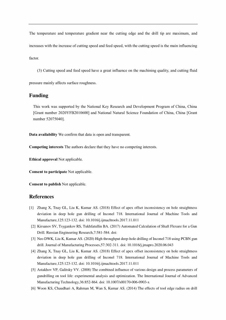
long tool life [3]. As shown in Fig. 1, gun drill is composed with drill bit, drill pipe and drill handle.
Generally, small diameter gun drills are formed by welding once, and the drill bit cannot be replaced.
Larger diameter gun drills with blades can be replaced after the blades are worn out. The drill bit is the
most important part of the gun drill, which undertakes the main drilling work. It is generally made of hard
alloy and tool steel, with higher requirements on strength and wear resistance [4]. The tip part of the drill
bit is the cutting edge, and the circumference part is distributed with the guide block with the function of
guiding and polishing, which can improve the machining accuracy of the hole. Generally, there is no need
for reaming. In addition, since the gun drill has a unilateral cutting edge, the guide strip also has the
function of balancing the radial cutting force on the cutting edge, and a reasonable guide block layout can
keep the drilling process more stable. The drill pipe is used for chip removal and cutting fluid flow. It is
usually made of seamless steel pipe. The drill pipe usually has a "V" groove structure, and the multi-blade
gun drill has two V-grooves , through which the chip is discharged under the action of high pressure cutting
fluid. The diameter of the drill pipe is slightly smaller than that of the bit, and the drill pipe is hollow inside,
which is used for transmitting cutting fluid. The size design of the V-shaped groove and the through-oil
hole should consider the rigidity of the drill pipe and the efficiency of through-oil and chip removal. The
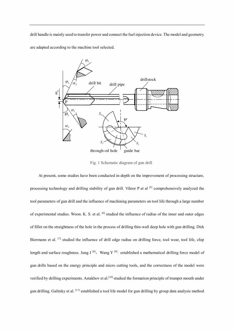
drill handle is mainly used to transfer power and connect the fuel injection device. The model and geometry
are adapted according to the machine tool selected.
drill bit drill pipe
drillstock
dm
1
2
3
1
2
3
P
1S
2S 3S
4S
through-oil hole guide bar
Fig. 1 Schematic diagram of gun drill
At present, some studies have been conducted in-depth on the improvement of processing structure,
processing technology and drilling stability of gun drill. Viktor P et al [5] comprehensively analyzed the
tool parameters of gun drill and the influence of machining parameters on tool life through a large number
of experimental studies. Woon. K. S. et al. [6] studied the influence of radius of the inner and outer edges
of fillet on the straightness of the hole in the process of drilling thin-wall deep hole with gun drilling. Dirk
Biermann et al. [7] studied the influence of drill edge radius on drilling force, tool wear, tool life, chip
length and surface roughness. Jung J [8],Wang Y [9] established a mathematical drilling force model of
gun drills based on the energy principle and micro cutting tools, and the correctness of the model were
verified by drilling experiments. Astakhov et al.[10] studied the formation principle of trumpet mouth under
gun drilling. Galitsky et al. [11] established a tool life model for gun drilling by group data analysis method
(GMDH) including tool angle parameters and process parameters, which was a relatively perfect tool life
prediction model. Klocke et al. [12] established a finite element analysis model of gun drilling process based
on Deform-3D, and the simulation results were basically consistent with the experimental results by
adjusting the radius of cutter blade circle and friction coefficient in the model. Yongguo Wang et al. [13]
studied the corresponding relationship between the chip morphology and surface morphology under
different tool wear conditions during gun drilling. On machining stability and straightness control,
Alexander [14] studied the nonlinear bending vibration and torsional vibration in the gun drilling process,
simplified the drill pipe into a continuous beam model, then proposed a new bending-torsional coupled
vibration drilling model combined with the intermittent cutting theory. Tarng [15] developed a flutter
identification system based on the ART2 neural network method, which could effectively identify the drill
pipe vibration in the process of gun drilling. Kirsanov [2], Chin et al [16]. used finite element method to
simulate the vibration and bending of drill pipe in the process of gun drilling.
However, there are still some problems in the gun drilling process, such as insufficient processing
mechanism, lack of quantitative research on the influence of machining parameters, clamping error, tool
parameters and other factors on machining quality, and low simulation accuracy. In this paper, the drilling
force, drilling heat and machining quality of gun drilling are studied, especially for the influence of
machining parameters on drilling force, drilling temperature and machining quality by combining theory,
experiment and simulation.
2. Experimental procedures
A high strength steel 42CrMo round bar is used as the workpiece. The processing equipment adopted
is the deep-hole gun drilling machine tool, Beijing Jinuo deep-hole equipment company. The tool is
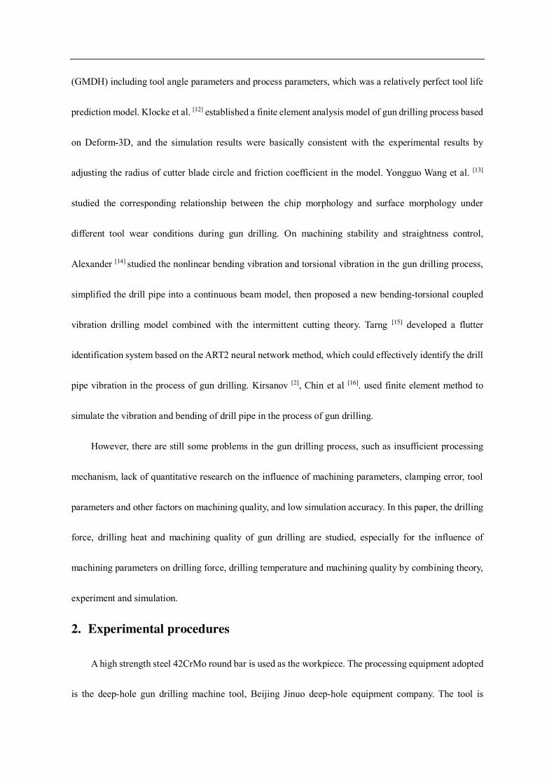
German Cobalt Collar gun drill, the bit parameters are generally standard parameters, shown in Table 1.
Table 1 Bit parameters
External
angle
Internal
angle
Tool tip
back angle
Groove
angle
Inclination angle of
diversion surface
Center distance
of tool tip
40° 30° 38° 120° 20° 1 mm
The dynamometer used in this experiment is Type 9257 plate dynamometer produced by Kistler,
Swiss. The main components include flat-panel dynamometer, signal collector, charge amplifier and the
supporting PC DynoWare cutting force measurement and analysis software.
The drilling machine is a horizontal machine tool. The cutting fluid is pumped into the spindle and the drilling hole of the gun from the tail of the machine tool by the high pressure pump. It flows out through the head of the bit and discharges the chips into the chip container. The workpiece is fixed onto the dynamometer, and the dynamometer sensor collects the cutting force signals in the drilling process. After signal processing and amplification, the measured cutting force values are presented on DynoWare . The schematic diagram of test platform construction is shown in Fig. 2, and the experimental parameters are shown in
Table 2.
Fig. 2 Schematic diagram of gun drill drilling force measurement test platform
Table 2 Experimental parameters.

Cutting speed (rpm) 30 40 45 50 55 60
Feed speed (μm/r) 4 6 8 10 12
Cutting fluid pressure (MPa) 3 4 5 6
Hole depth (mm) 100
Hole diameter (mm) 4
After processing, the axis deviation, roundness and aperture size are measured using Hexagon Global
Advantage coordinate measuring machine. The workpiece coordinate system is established based on the
process datum (front and left side of the workpiece) corrected during machining. The diameter, roundness
and center coordinates of the hole entrance-side and exit-side are measured respectively under the
workpiece coordinate system, shown in Fig. 3.
Fig. 3 Sketch of workpiece coordinate system
The surface morphology of the inner hole and the surface roughness were measured using Keyence
3D laser scanning microscope. In this paper, the machining hole is planed along the axis by wire cutting
method, and then the surface topography is taken at three positions, i.e. 4 mm from the hole entrance, 4
mm from the middle of the hole and 4 mm from the exit of the hole, respectively. As shown in Fig. 4, each
position was measured three times, and roughness was calculated in VK analysis software.

1-Inlet measurement
position
2-Middle measurement
position
3-Outlet measurement
position
Hole 4 (Oil presure
6 MPa)
Hole 3 (Oil presure
5 MPa)
Hole 2 (Oil presure
4 MPa)
Hole 1 (Oil presure
3 MPa)
Fig. 4 Sketch map of surface roughness measurement position
3. Gun drilling thermodynamic coupling model
3.1 Mechanical numerical model
The force of the drill bit is complicated [17], which can be divided into normal force, circumferential
and axial friction force on the support surface of the guide strip, normal force and tangential friction force
on the inner and outer cutting edges, and normal force formed by the cutting fluid on the outer diameter
clearance surface. The overall stress analysis is shown in Fig. 5.
outer edge
inner edge
guide bar
direction of rotation
normal force
friction force
X
Y
blade clearance
Fig. 5 Analysis of the overall stress of the drill bit

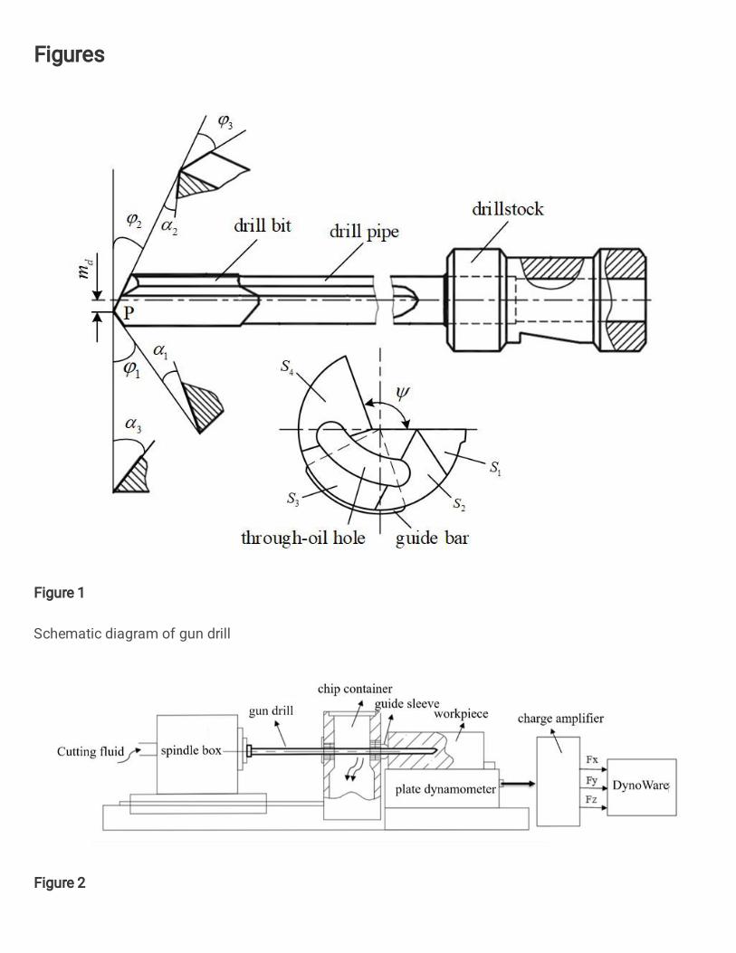
As shown in Fig. 6, the normal force on the support surface of the guide bar is simplified as 𝑅𝑝 and
the circumferential friction force is decomposed into 𝑅𝑓𝑥 and 𝑅𝑓𝑦 along X and Y directions. 𝑅𝑝 can be
described by the following formula : 𝑅𝑝 = 𝑝𝛿𝑟(𝜃2 − 𝜃1) (1)
Where, p is the unit normal force, 𝑟 is the drilling radius, 𝜃1 and 𝜃2 is the starting angle and the
ending angle of the drilling guide bar, 𝛿 is the contact area between the guide bar and the inner wall of
the hole in the Z-axis direction. The 𝑅𝑝 direction is at the center of the drill and the action point is
(𝜃1 + 𝜃2)/2.
pRfyR
fxR
X
Y
1
2
cosp r
pr
Fig. 6 Simplified force decomposition on guide bar
The circumferential friction force on the guide bar is decomposed into 𝑅𝑓𝑥 and 𝑅𝑓𝑦 , According to
the triangle decomposition in the figure, when 𝜃1 ≤ 𝜔 ≤ 𝜋/2, the element's circumferential friction force
𝑑𝑅𝑓𝑥 along the minus X axis, 𝑅𝑓𝑥 can be expressed as:

1 1
2 21cos sin cos
2fx
R p r d p r d p r
(2)
When 𝜋/2 ≤ 𝜔 ≤ 𝜃2, 𝑑𝑅𝑓𝑥 along the minus X axis, 𝑅𝑓𝑥 can be expressed as:
2 2
2
2 2
cos sin cos2
fxR p r d p r d p r
(3)
Where, 𝜇 is the friction coefficient, 𝜔 is the angle variable.
Therefore, at the top 𝜃1 ≤ 𝜔 ≤ 𝜃2, 𝑅𝑓𝑥 can be expressed as:
1 2(cos cos )fx
R p r (4)
Similarly, 𝑅𝑓𝑦 along the Y axis, and the expression of 𝑅𝑓𝑦 is:
2 1 1 2(1 sin ) (1 sin ) (sin sin )fy
R p r p r p r (5)
Suppose the axial friction coefficient on the guide bar is 𝜇𝐿, the axial friction force 𝑅𝑡 on the guide
bar can be expressed as:
2
12 1t L L L p
R p rd p r R
(6)
Due to the special single-edge structure of the gun drill, the cutting speed at each point of the inside
and outside edges is different, and the cutting force distributed along the cutting edge is un-uniform.
Therefore, the internal and external cutting edges are divided into countless micro elements by the micro
element method, and each micro element can be regarded as a cutting element. If the number of micro-
element is large enough and the area of micro-element is small enough, the cutting speed on each micro-
element can be considered as unchanged [18]. After the cutting force on each micro-element is obtained,
the cutting force on the whole cutting edge can be obtained by integrating along the cutting edge.
Then the normal force 𝐹𝑛1 and friction force 𝐹𝑓1 on the outer edge can be expressed as:

1 1 1
1 1
m m
n n c n
j j
F K j dA j t K j dx j
(7)
1 1 1
1 1
m m
f f c f
j j
F K j dA j t K j dx j
(8)
Similarly, the normal force 𝐹𝑛2 and friction force 𝐹𝑓2 on the inner edge can be expressed as:
2 2 2
1 1
n n
n n c n
j j
F K j dA j t K j dx j
(9)
2 2 2
1 1
n n
f f c f
j j
F K j dA j t K j dx j
(10)
In the process of gun drilling, the cutting force mainly comes from the decomposition of the normal
force and friction force on the guide bar and cutting edge as well as the clearance water pressure in XYZ
directions. According to the principle of force balance, the forces are decomposed in X and Y directions,
seen as follows [9]:
0 11 21 2 sin( ) sin( )
2 2n n fy p hF F R R R
(11)
0 11 21 2cos( ) cos( )
2 2p fx s s hR R F F R
(12)
For convenience of calculation, let 𝜉 = 𝜋𝑛30,𝜉𝑎1 = 𝑎2 + 𝑎4 + 𝑙𝑛 𝑡𝑐1 + 1, 𝜉𝑏1 = 𝑏2 + 𝑏4 + 𝑙𝑛 𝑡𝑐1 +1, 𝜉𝑎2 = 𝑎2 + 𝑎4 + 𝑙𝑛 𝑡𝑐2 + 1 and 𝜉𝑏2 = 𝑏2 + 𝑏4 + 𝑙𝑛 𝑡𝑐2 + 1. Where, 𝑡𝑐 are actual cutting thickness; ,
1 and 2 are the outer and inner angles of the gun drill respectively; 𝑎0 − 𝑎4 and 𝑏0 − 𝑏4 are model
calibration coefficients. In combination with vertical (11) and (12), the expression of positive pressure 𝑅𝑝
on the support surface of the guide bar is obtained as follows:
1 2 1 21 2 1 2
1 21 1 1 1
tan cos2 2R
tan cos cos sin sin2
s s n n
p
fx fy
F F F F r
F F
(13)
During drilling, the main cutting force is feed resistance. Feed force 𝐹𝑍 is mainly composed of two

parts: the friction force 𝑅𝑡 along the Z direction of the guide bar and the component force 𝐹𝑡 of the
friction force on the cutting edge in the Z direction. Here 𝐹𝑡 = 𝐹𝑡1 + 𝐹𝑡2 = 𝐹𝑓1 𝑐𝑜𝑠 𝜑1 + 𝐹𝑓2 𝑐𝑜𝑠 𝜑2,so
𝐹𝑍 can be represented as:
3 10
3 2 20
1 1 2 2
1
1 1 2
1
2 2 1
F cos cos
1 sin 1 cos
1 sin 1 cos
b
b b
z t t L p f f
bb b
c n b d
bb b
c n b d L p
R F R F F
e t f m
e t f r m R
(14)
3.2 Thermodynamic coupling finite element model
Due to the small heat dissipation space in the drilling process, the workpiece and tool absorb most of
the cutting heat, and the chip takes away only about 30% of the heat. The workpiece expansion caused by
the cutting heat will affect the machining precision, especially in the deep hole machining, the cutting heat
has a great influence on the diameter deviation of the machining hole [19].
In this paper, the finite element model of gun drilling is established by Deform-3D. In this model, the
radius of the cutting edge circle is not considered, and the it is assumed to be absolutely sharp. The effect
of the cutting fluid and the through-oil hole are also without considered . In order to facilitate the grid
division, the through-oil hole is removed and simplified. For reduce the number of grids and improve the
computational efficiency, only a small part of bits involved in cutting are retained in the simulation. The
shapes of the meshed workpiece and cutter are shown in Fig. 7. The material model of the workpiece is
defined as the Johnson-Cook model, and the parameters are shown in Table 3[14].
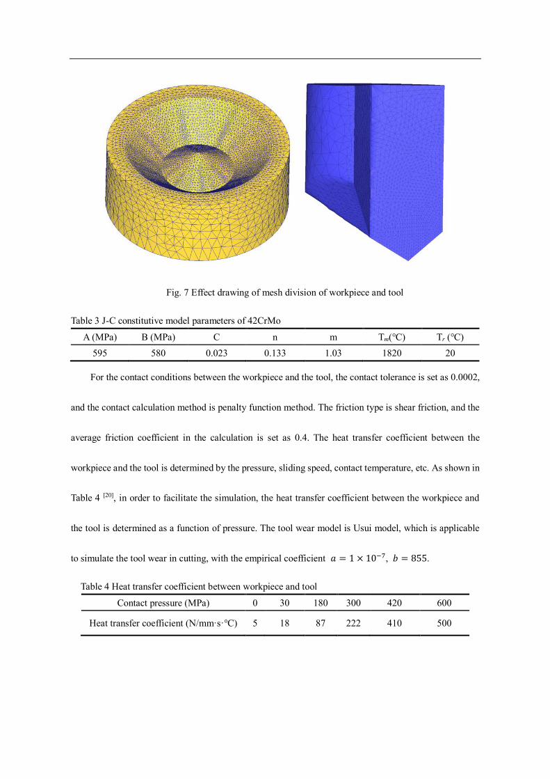
Fig. 7 Effect drawing of mesh division of workpiece and tool
Table 3 J-C constitutive model parameters of 42CrMo
A (MPa) B (MPa) C n m Tm(℃) Tr (℃) 595 580 0.023 0.133 1.03 1820 20
For the contact conditions between the workpiece and the tool, the contact tolerance is set as 0.0002,
and the contact calculation method is penalty function method. The friction type is shear friction, and the
average friction coefficient in the calculation is set as 0.4. The heat transfer coefficient between the
workpiece and the tool is determined by the pressure, sliding speed, contact temperature, etc. As shown in
Table 4 [20], in order to facilitate the simulation, the heat transfer coefficient between the workpiece and
the tool is determined as a function of pressure. The tool wear model is Usui model, which is applicable
to simulate the tool wear in cutting, with the empirical coefficient 𝑎 = 1 × 10⁻⁷, 𝑏 = 855.
Table 4 Heat transfer coefficient between workpiece and tool
Contact pressure (MPa) 0 30 180 300 420 600
Heat transfer coefficient (N/mm·s·℃) 5 18 87 222 410 500

4. Experiment results and discussion
4.1 Thermodynamic coupling model results of drilling
Fig. 8 shows the variation curve of drilling force with hole depth at each cutting speed and feed speed.
Because the radial cutting forces Fx and Fy fluctuate up and down on the coordinate axis, and the average
value is close to 0. This paper mainly analyzes the feed resistance Fz, and the drilling forces mentioned
below all represent Fz. At the same time, the speed of the maximum diameter on the outer edge of the gun
drill is selected as the cutting speed.With the increase of drilling depth, the drilling force gradually
increases. When the hole is relatively shallow, the increasing speed and amplitude of the drilling force are
relatively large, which may be related to the friction force. With the increase of hole depth, the drilling
force increases by more than 30%, indicating that the drilling state is not always stable in the process of
deep hole drilling. This leads to the difference of drilling force in different depths of holes, and it will also
affect the dimensional accuracy and surface quality at different depths. The variation of cutting force can
be used as an effective factor to represent the variation of cutting state.
0 20 40 60 80 10010
20
30
40
50
60
70
Dri
llin
g f
orc
e (N
)
Drilling depth (mm)
30(m/min)
40(m/min)
45(m/min)
50(m/min)
55(m/min)
60(m/min)
0 20 40 60 80 10020
30
40
50
60
70
80
Dri
llin
g f
orc
e (N
)
Drilling depth (mm)
0.004(mm/r)
0.006(mm/r)
0.008(mm/r)
0.010(mm/r)
0.012(mm/r)
(a) (b)
Fig. 8 Comparison of drilling force with hole depth under different cutting speed (a) and
feed speed (b)

The values of each cutting speed and feed speed were substituted into Equation (24) to calculate the
predicted values of the theoretical model of drilling force. Meanwhile, the average of the measured values
was taken and the comparison curve of the predicted and measured values was drawn according to the
result data, as shown in Fig. 9. It can be seen that with the increase of cutting speed, the predicted value
of cutting force decreases gradually. In addition to the results under 45 m/min, the measured values also
show a general trend of decreasing with the increase of cutting speed, and the decreasing speed is faster
under high speed. This indicates that increasing spindle speed can reduce the drilling feed resistance and
improve the stability of machining system. At the same time, according to the theoretical results, the
relationship between drilling force and feed velocity is close to linear growth. Although there is no obvious
linear relationship between experimental values, the overall size of drilling force increases with the
increase of feed speed. The main reason is that the increase of feed speed f leads to the increase of cutting
thickness 𝑡𝑐 and instantaneous cutting area, which leads to the increase of tool load and axial feed
resistance. The variation trend is basically the same, with the maximum error about 10%, which verifies
the correctness of the established mathematical model of drilling force.
30 35 40 45 50 55 60
44
46
48
50
52
54
56
58
Cu
ttin
g f
orc
e (N
)
Cutting speed (m/min)
Measured value
Theoretical value
0.004 0.006 0.008 0.010 0.012
52
54
56
58
60
62
64
66
68
Cutt
ing f
orc
e (N
)
Feed speed (mm/r)
Measured value
Theoretical value
(a) (b)
Fig. 9 Comparison of drilling force and cutting speed (a) and feed speed (b)
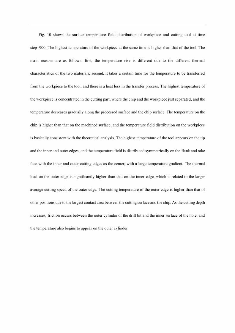
Fig. 10 shows the surface temperature field distribution of workpiece and cutting tool at time
step=900. The highest temperature of the workpiece at the same time is higher than that of the tool. The
main reasons are as follows: first, the temperature rise is different due to the different thermal
characteristics of the two materials; second, it takes a certain time for the temperature to be transferred
from the workpiece to the tool, and there is a heat loss in the transfer process. The highest temperature of
the workpiece is concentrated in the cutting part, where the chip and the workpiece just separated, and the
temperature decreases gradually along the processed surface and the chip surface. The temperature on the
chip is higher than that on the machined surface, and the temperature field distribution on the workpiece
is basically consistent with the theoretical analysis. The highest temperature of the tool appears on the tip
and the inner and outer edges, and the temperature field is distributed symmetrically on the flank and rake
face with the inner and outer cutting edges as the center, with a large temperature gradient. The thermal
load on the outer edge is significantly higher than that on the inner edge, which is related to the larger
average cutting speed of the outer edge. The cutting temperature of the outer edge is higher than that of
other positions due to the largest contact area between the cutting surface and the chip. As the cutting depth
increases, friction occurs between the outer cylinder of the drill bit and the inner surface of the hole, and
the temperature also begins to appear on the outer cylinder.

Fig. 10 Temperature distribution nephogram of workpiece and tool at step = 900
As shown in Fig. 11, the workpiece cutting area is divided along depth to analyze the distribution of
temperature field. It can be seen that the temperature starts from the cutting area and gradually decreases
along the depth, indicating that the drilling heat is transferred from the cutting area to the workpiece interior,
which cause the workpiece interior temperature to rise. By magnifying the chip root position, it can be
seen that the temperature contour distribution is dense and the temperature gradient is large. At the same
time, the distribution of temperature field also exists in the area between the chip and the rough surface
(the first deformation area), indicating that the cutting heat is generated in this area, which is consistent
with the mechanism of cutting heat generation.
Fig. 11 Distribution of workpiece temperature field along depth
The vertical cutting edge dissects the bit along the axis are shown in Fig. 12, .Compared with the
workpiece, the temperature distribution on the bit is more concentrated, and the heat transfer range along
the axis is shallow. It shows that in the process of drilling, a lot of heat is gathered near the drill tip and
cutting edge, and the heat diffuses slowly to the inside of the drill bit. The heat dissipation mainly depends
on the heat dissipation medium. It can be seen that good cutting fluid cooling is important for gun drilling.
It can be predicted from the characteristics of the cutting temperature field that the wear of the gun drill
should mainly occur on the front surface near the outer edge and tip.
Fig. 12 Cloud chart of temperature field along axial depth on bit
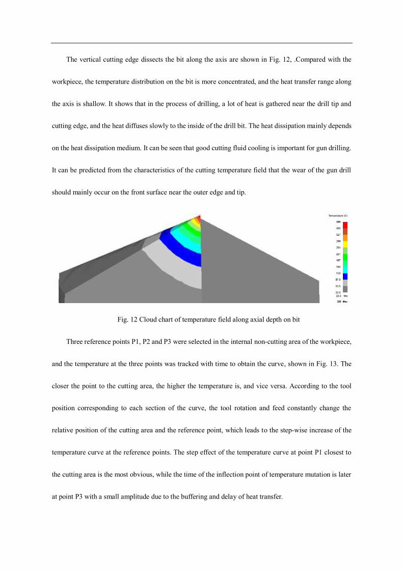
Three reference points P1, P2 and P3 were selected in the internal non-cutting area of the workpiece,
and the temperature at the three points was tracked with time to obtain the curve, shown in Fig. 13. The
closer the point to the cutting area, the higher the temperature is, and vice versa. According to the tool
position corresponding to each section of the curve, the tool rotation and feed constantly change the
relative position of the cutting area and the reference point, which leads to the step-wise increase of the
temperature curve at the reference points. The step effect of the temperature curve at point P1 closest to
the cutting area is the most obvious, while the time of the inflection point of temperature mutation is later
at point P3 with a small amplitude due to the buffering and delay of heat transfer.
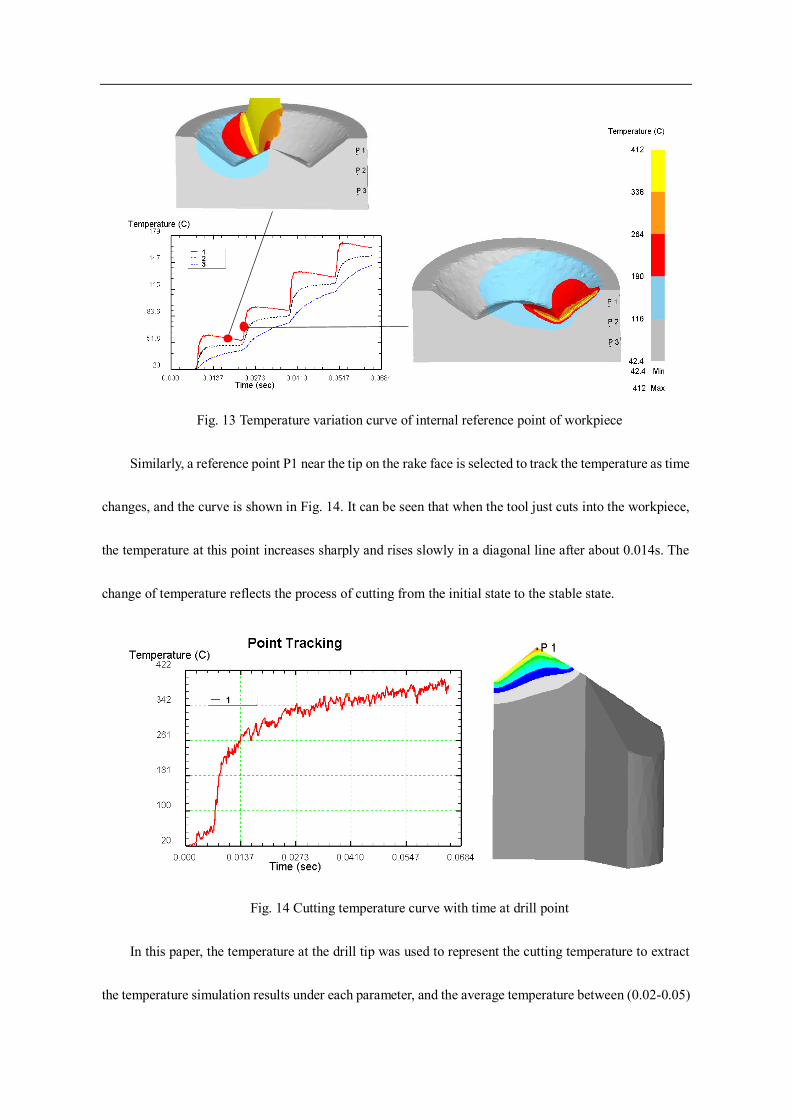
Fig. 13 Temperature variation curve of internal reference point of workpiece
Similarly, a reference point P1 near the tip on the rake face is selected to track the temperature as time
changes, and the curve is shown in Fig. 14. It can be seen that when the tool just cuts into the workpiece,
the temperature at this point increases sharply and rises slowly in a diagonal line after about 0.014s. The
change of temperature reflects the process of cutting from the initial state to the stable state.
Fig. 14 Cutting temperature curve with time at drill point
In this paper, the temperature at the drill tip was used to represent the cutting temperature to extract
the temperature simulation results under each parameter, and the average temperature between (0.02-0.05)

s was calculated to draw the graph shown in Fig. 15. As the cutting speed increases, the cutting temperature
shows a linear trend of increasing, and the growth rate is faster at high feed speed. When the cutting speed
is constant, the cutting temperature increases with the increase of feed speed, and it is sensitive to the
change of the feed speed at low feed rate.
30 40 50 60 70100
150
200
250
300
350
400
450
Tem
per
atu
re (
°C)
Cutting speed (m/min)
0.004(mm/r)
0.006(mm/r)
0.008(mm/r)
0.010(mm/r)
0.012(mm/r)
Fig. 15 Comparison of cutting temperature and cutting speed under different feed speed
4.2 Effect of processing parameters on processing quality
In the process of gun drilling, there are problems of drill pipe length, poor rigidity, gap between drill
bit and guide sleeve, drill pipe vibration, rotary vibration in the guide sleeve clearance repeatedly, which
lead to the deviation between drill hole diameter and tool diameter and hole roundness error. Tool wear,
cutting heat and other factors also lead to hole inlet and outlet diameter deviation.
It can be seen from Fig. 16 and Fig. 17 that the diameter of entrance of the hole should be larger than
that of the exit. With the increases of cutting speed, the diameter of the exit decreases more and more, and
that of the entrance also fluctuates to a certain extent, but the range is relatively small. The diameter
deviation of the entrance and exit shows a linear rising trend with the increases of cutting speed. The
diameter change at the entrance can be attributed to the wear of the guide bar and the random error of

measurement. The diameter of the hole outlet is obviously smaller than the gun drill, which is related to
the cutting temperature. According to the simulation analysis, in the process of gun drilling, the drilling
temperature is relatively high, and increases with the increase of cutting speed. A large amount of cutting
heat is transferred to the workpiece, and the temperature near the hole is high, and rises rapidly due to the
slow heat dissipation of the workpiece with larger hole depth. Due to the effect of thermal expansion and
cold contraction, the workpiece expanded during drilling, and then its temperature gradually returned to
room temperature after drilling, leading to the shrinkage of the material and the reduction of the hole
diameter. The faster the cutting speed, the higher the cutting temperature. The obvious effect of heat
expansion and cold contraction results in the hole inlet and outlet diameter deviation.
It can be seen from the roundness error curve in Fig. 18 that the roundness error at the entrance of the
hole is smaller than the exit, which is related to the inconsistency of the internal shrinkage rate of the
material. With the increase of feed velocity, the diameters of inlet and outlet are with some fluctuation, but
the variation range is small, and the diameter deviation has little change. The roundness error of the inlet
is smaller than that of the outlet, but the feed velocity has little influence on the diameter error and
roundness error of the inlet and outlet. With the increase of cutting fluid pressure, the hole exits basic
remain stable, the diameter difference of the inlet and outlet is less. That is because as the cutting fluid
pressure and flow rate increases, the cooling performance of gun drill system reduces the cutting
temperature. But the pressure strengthen the pipe eddy effect and the drill string vibration, resulting in the
hole roundness error increases.

30 40 50 603.970
3.975
3.980
3.985
3.990
3.995
4.000
4.005
4.010
Dia
met
er (
mm
)
Cutting speed (m/min)
Entrance end
Exit end
0.006 0.008 0.010 0.0123.980
3.985
3.990
3.995
4.000
4.005
4.010
4.015
4.020
Dia
met
er (
mm
)
Feed speed (m/min)
Entrance end
Exit end
3 4 5 6
3.984
3.988
3.992
3.996
4.000
4.004
4.008
4.012
4.016
Dia
met
er (
mm
)
Oil pressure (Mpa)
Entrance end
Exit end
(a) (b) (c)
Fig. 16 Comparison of diameter of hole inlet and outlet and cutting speed (a), feed speed (b) and oil
pressure (c)
30 40 50 600.008
0.012
0.016
0.020
0.024
0.028
Dia
met
er d
iffe
rence
(m
m)
Cutting speed (m/min)
0.006 0.008 0.010 0.0120.010
0.011
0.012
0.013
0.014
0.015
Dia
met
er d
iffe
ren
ce (
mm
)
Feed speed (mm/r)3 4 5 6
0.007
0.008
0.009
0.010
0.011
0.012
0.013
Dia
met
er d
iffe
ren
ce (
mm
)
Oil pressure (MPa)
(a) (b) (c)
Fig. 17 Comparison of diameter difference between inlet and outlet and cutting speed (a), feed
speed (b) and oil pressure (c)
30 40 50 600.00
0.01
0.02
0.03
0.04
0.05
Ro
un
dn
ess
(mm
)
Cutting speed (m/min)
Entrance end
Exit end
0.006 0.008 0.010 0.0120.01
0.02
0.03
0.04
0.05
Ro
un
dn
ess
(mm
)
Feed speed (mm/r)
Entrance end
Exit end
3 4 5 6
0.00
0.01
0.02
0.03
0.04
Ro
un
dn
ess
(mm
)
Oil pressure (Mpa)
Entrance end
Exit end
(a) (b) (c)
Fig. 18 Comparison of roundness of hole inlet and outlet and cutting speed (a), feed speed (b) and
oil pressure (c)

The axis deviation of long and thin deep holes is the most important parameter to represent their
machining quality. For spatial cross holes with high position accuracy, the axis deviation will lead to the
exit position deviation, which will affect the intersection of the hole system and oil transfer efficiency, and
even lead to the scrap of the workpiece. Axis deviation is mainly caused by the bending of the drill, which
is related to machining parameters, clamping accuracy, vibration and other factors.
Fig. 19 shows the axis deviation of deep hole under various drilling parameters. It can be seen that
the deviation in X direction (vertical direction) is much greater than that in Y direction (horizontal
direction), and the linear deviation of hole mainly depends on the variation of X-direction, which indicated
that the bending of gun drill mainly occurs in the gravity direction, and the deviation of hole axis is around
0.06 mm. With the increase of cutting speed, the deviations of Y axis and X axis show a slow rising trend.
This is caused by the increase of spindle speed, which decreases the machining stability of the drill pipe
and aggravates the vibration. At the same time, the increase of speed leads to the increase of feed per
minute, which increases the resistance of drilling feed and finally makes the drill pipe more prone to
bending. With the increase of feed speed, the Y-direction deviation shows a slow growth trend, and the X-
direction deviation fluctuates up and down, with a slight increase in the overall value. The change of linear
deviation is basically consistent with the X-direction deviation. This indicates that due to the increase of
feed speed, the axial feed resistance of drilling increases, which leads to the increase of the bending degree
of drilling gun, but the overall effect is small. With the increase of cutting fluid pressure, the Y-direction
deviation of hole axis increases, and the X-direction deviation also increases slightly. The variation of
cutting fluid pressure mainly affects the axis Y deviation, and this is related to the increase of pressure and
vortex effect of cutting fluid in the hole. Generally, the cutting fluid pressure has little influence on the

axis deviation of the hole.
30 40 50 600.00
0.02
0.04
0.06
0.08
Ax
is d
evia
tio
n (
mm
)
Cutting speed (m/min)
Y-direction deviation
X-direction deviation
Linear deviation
0.006 0.008 0.010 0.0120.00
0.02
0.04
0.06
0.08
Ax
is d
evia
tio
n (
mm
)
Feed speed (mm/r)
Y-direction deviation
X-direction deviation
Linear deviation
3 4 5 60.00
0.02
0.04
0.06
Axis
dev
iati
on (
mm
)
Oil pressure (MPa)
Y-direction deviation
X-direction deviation
Linear deviation
(a) (b) (c)
Fig. 19 Comparison of axis deviation and cutting speed (a), feed speed (b) and oil pressure (c)
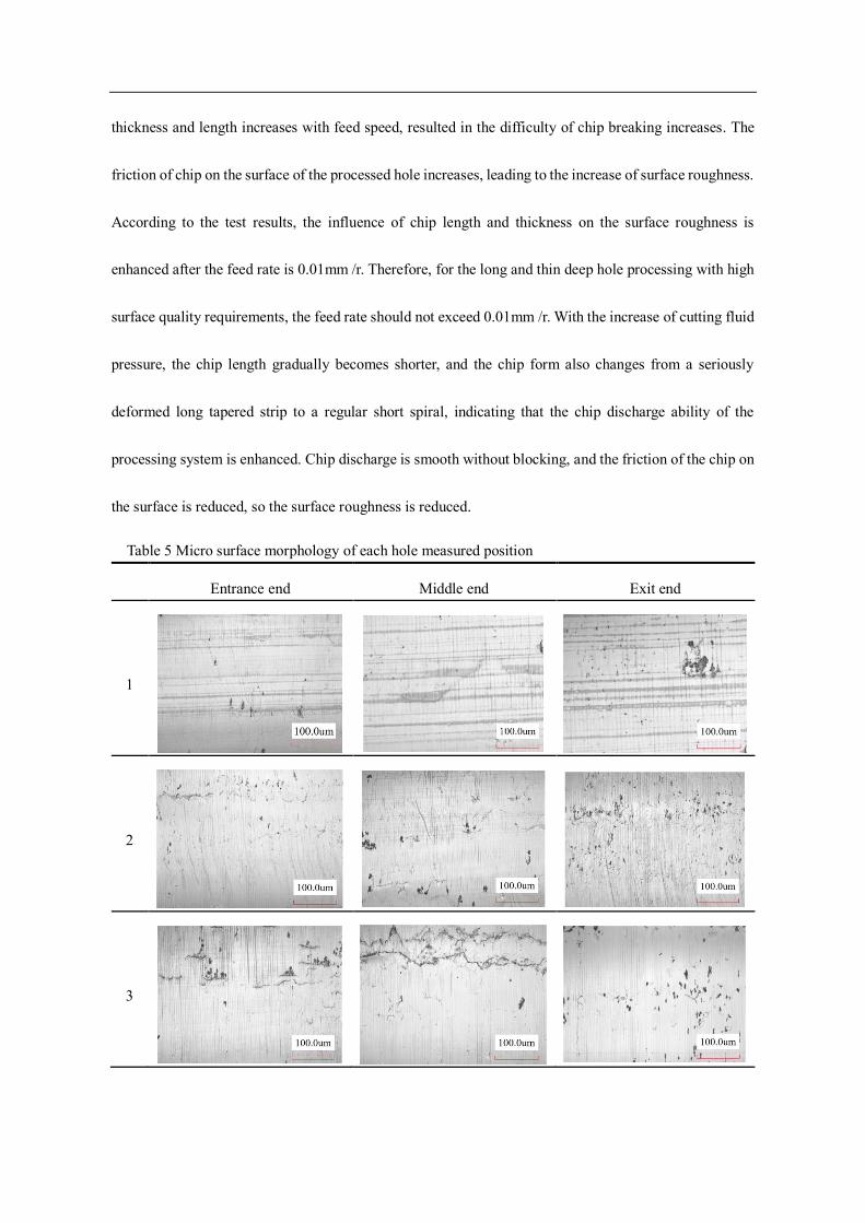
The surface micro morphologies of each hole measured position are shown in Table 5. It can be seen
from the micro morphology of the processed hole that the surface of the hole has surface defects such as
cracks, scratches, dense grooves and pits formed by material hard points falling off. With the decrease of
oil pressure, there are more scratches on the processed hole surface, and the surface will be rougher. In
gun drilling, the influence of tool deflection angle and edge circle radius on the surface of machined hole
is relatively small, while the friction and polishing of the guide strip on the machined hole wall and the
scraping of the chip have a great influence.
It can be seen from Fig. 20 that with the increase of cutting speed, the surface roughness of machined
hole gradually increases. The reason is that with the increase of cutting speed, cutting fluid is easy to form
eddy at the bottom of the hole, resulting in the reduction of chip discharge performance. This increases the
chip scraping on the machined surface, and small chips and hard point particles of the workpiece are easy
to get stuck in the gap between the guide strip and the hole wall. The faster the speed, the greater damage
to the hole wall. With the feed rate increases from 0.006 mm /r to 0.01 mm /r, the surface roughness of the
machining hole increases slowly, then it increases rapidly over 0.01 mm /r. That is because the chip
thickness and length increases with feed speed, resulted in the difficulty of chip breaking increases. The
friction of chip on the surface of the processed hole increases, leading to the increase of surface roughness.
According to the test results, the influence of chip length and thickness on the surface roughness is
enhanced after the feed rate is 0.01mm /r. Therefore, for the long and thin deep hole processing with high
surface quality requirements, the feed rate should not exceed 0.01mm /r. With the increase of cutting fluid
pressure, the chip length gradually becomes shorter, and the chip form also changes from a seriously
deformed long tapered strip to a regular short spiral, indicating that the chip discharge ability of the
processing system is enhanced. Chip discharge is smooth without blocking, and the friction of the chip on
the surface is reduced, so the surface roughness is reduced.
Table 5 Micro surface morphology of each hole measured position
Entrance end Middle end Exit end
1
2
3

4
30 40 50 600.45
0.50
0.55
0.60
0.65
0.70
0.75
Ra of entrance end
Ra of middle end
Ra of exit end
Ra
(m
)
Cutting speed (m/min)0.006 0.008 0.010 0.012
0.40
0.45
0.50
0.55
0.60
0.65
0.70
Ra of entrance end
Ra of middle end
Ra of exit end
Ra
(m
)
Feed speed (m/min)
3 4 5 60.40
0.45
0.50
0.55
0.60
0.65
0.70
0.75
Ra
(m
)
Oil pressure (Mpa)
Ra of entrance end
Ra of middle end
Ra of exit end
(a) (b) (c)
Fig. 20 Comparison of surface roughness and cutting speed (a), feed speed (b) and oil pressure (c)
5. Conclusion
In this paper, 42CrMo high-strength steel is selected as the experimental material. Based on the
drilling mechanism of gun drilling, combined with finite element simulation and processing test, the
influence of processing parameters on drilling force, drilling temperature and processing quality is
analyzed. The main contents of the study are summarized as follows:
(1) Numerical model analysis and experimental verification of drilling force are carried out. The
drilling force tends to increase rapidly and then become stable with the increase of hole depth, and
decreases with the increase of cutting speed and increases with feed speed. The maximum error between
experimental data and theoretical value is less than 10%.
(2) The finite element simulated temperature and temperature gradient near the chip root are the
largest, and the temperature in the uncut area of the workpiece rises in a stepped manner with the tool feed.
The temperature and temperature gradient near the cutting edge and the drill tip are maximum, and
increases with the increase of cutting speed and feed speed, with the cutting speed is the main influencing
factor.
(3) Cutting speed and feed speed have a great influence on the machining quality, and cutting fluid
pressure mainly affects surface roughness.
Funding
This work was supported by the National Key Research and Development Program of China, China [Grant number 2020YFB2010600] and National Natural Science Foundation of China, China [Grant number 52075040].
Data availability We confirm that data is open and transparent.
Competing interests The authors declare that they have no competing interests.
Ethical approval Not applicable.
Consent to participate Not applicable.
Consent to publish Not applicable.
References
[1] Zhang X, Tnay GL, Liu K, Kumar AS. (2018) Effect of apex offset inconsistency on hole straightness
deviation in deep hole gun drilling of Inconel 718. International Journal of Machine Tools and
Manufacture,125:123-132. doi: 10.1016/j.ijmachtools.2017.11.011
[2] Kirsanov SV, Tsygankov RS, Tukhfatullin BA. (2017) Automated Calculation of Shaft Flexure for a Gun
Drill. Russian Engineering Research,7:581-584. doi:
[3] Neo DWK, Liu K, Kumar AS. (2020) High throughput deep-hole drilling of Inconel 718 using PCBN gun
drill. Journal of Manufacturing Processes,57:302-311. doi: 10.1016/j.jmapro.2020.06.043
[4] Zhang X, Tnay GL, Liu K, Kumar AS. (2018) Effect of apex offset inconsistency on hole straightness
deviation in deep hole gun drilling of Inconel 718. International Journal of Machine Tools and
Manufacture,125:123-132. doi: 10.1016/j.ijmachtools.2017.11.011
[5] Astakhov VP, Galitsky VV. (2008) The combined influence of various design and process parameters of
gundrilling on tool life: experimental analysis and optimization. The International Journal of Advanced
Manufacturing Technology,36:852-864. doi: 10.1007/s00170-006-0903-x
[6] Woon KS, Chaudhari A, Rahman M, Wan S, Kumar AS. (2014) The effects of tool edge radius on drill

deflection and hole misalignment in deep hole gundrilling of Inconel-718. CIRP Annals,63:125-128. doi:
10.1016/j.cirp.2014.03.075
[7] Biermann D, Wolf M, Aßmuth R. (2012) Cutting Edge Preparation to Enhance the Performance of Single
Lip Deep Hole Drills. Procedia CIRP,1:172-177. doi: 10.1016/j.procir.2012.04.030
[8] Jung J, Ke F. (2007) A gundrilling force system. International Journal of Machine Tools and
Manufacture,47:1276-1284. doi: 10.1016/j.ijmachtools.2006.08.018
[9] Wang Y, Jia W, Zhang J. (2014) The force system and performance of the welding carbide gun drill to cut
AISI 1045 steel. The International Journal of Advanced Manufacturing Technology,74:1431-1443. doi:
10.1007/s00170-014-6072-4
[10] Astakhov VP. (2002) The mechanisms of bell mouth formation in gundrilling when the drill rotates and
the workpiece is stationary. Part 2: the second stage of drill entrance. International journal of machine
tools & manufacture,42:1145-1152. doi: 10.1016/S0890-6955(02)00051-2
[11] Astakhov VP, Galitsky VV. (2005) Tool life testing in gundrilling: an application of the group method of
data handling (GMDH). International Journal of Machine Tools and Manufacture,45:509-517. doi:
10.1016/j.ijmachtools.2004.09.003
[12] Klocke F, Abouridouane M, Gerschwiler K, Lung D. (2011) 3D Modelling and Simulation of Gun Drilling.
Advanced Materials Research,223:12-19. doi: 10.4028/www.scientific.net/AMR.223.12
[13] Wang Y, Yan X, Li B, Tu G. (2012) The study on the chip formation and wear behavior for drilling forged
steel S48CS1V with TiAlN-coated gun drill. International Journal of Refractory Metals and Hard
Materials,30:200-207. doi: 10.1016/j.ijrmhm.2011.08.010
[14] Gouskov AM, Butcher EA, Voronov SA, Sinha SC. (2005) NONLINEAR FLEXURAL-TORSIONAL
VIBRATIONS OF A GUNDRILLING TOOL. ASME 2005 International Design Engineering Technical
Coference. doi:
[15] Tarng YS, Li TC. (1995) Adaptive Pattern Recognition of Drilling Chatter. Journal of Materials Processing
Technology:247-253. doi:
[16] Chin J, Sheu S. (2007) Strengths and weaknesses of finite element modeling deep hole drilling as
compared with beam and column equations. The International Journal of Advanced Manufacturing
Technology,32:229-237. doi: 10.1007/s00170-005-0332-2
[17] Li L, He N, Hao X, Yang Y. (2019) Deep-hole gun drilling mechanics model of Ti6Al4V alloy based on
Johnson and Cook flow stress model. The International Journal of Advanced Manufacturing
Technology,104:4497-4508. doi: 10.1007/s00170-019-04244-6
[18] AR W. (1985) Drilling model for cutting lip and chisel edge and comparison of experimental and predicted
results. Int J Mach Tool Design Res,4:347-365. doi:
[19] Neo DWK, Liu K, Kumar AS. (2020) High throughput deep-hole drilling of Inconel 718 using PCBN gun
drill. Journal of Manufacturing Processes,57:302-311. doi: 10.1016/j.jmapro.2020.06.043
[20] Agmell M, Ahadi A, Ståhl J. (2013) The Link Between Plasticity Parameters and Process Parameters in
Orthogonal Cutting. Procedia CIRP,8:224-229. doi: 10.1016/j.procir.2013.06.093
Figures
Figure 1
Schematic diagram of gun drill
Figure 2

Schematic diagram of gun drill drilling force measurement test platform
Figure 3
Sketch of workpiece coordinate system
Figure 4
Sketch map of surface roughness measurement position

Figure 5
Analysis of the overall stress of the drill bit
Figure 6
Simpli�ed force decomposition on guide bar

Figure 7
Effect drawing of mesh division of workpiece and tool
Figure 8
Comparison of drilling force with hole depth under different cutting speed (a) and feed speed (b)

Figure 9
Comparison of drilling force and cutting speed (a) and feed speed (b)
Figure 10
Temperature distribution nephogram of workpiece and tool at step = 900

Figure 11
Distribution of workpiece temperature �eld along depth
Figure 12
Cloud chart of temperature �eld along axial depth on bit
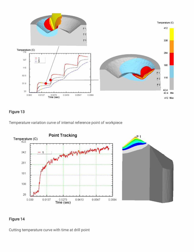
Figure 13
Temperature variation curve of internal reference point of workpiece
Figure 14
Cutting temperature curve with time at drill point

Figure 15
Comparison of cutting temperature and cutting speed under different feed speed
Figure 16
Comparison of diameter of hole inlet and outlet and cutting speed (a), feed speed (b) and oil pressure (c)

Figure 17
Comparison of diameter difference between inlet and outlet and cutting speed (a), feed speed (b) and oilpressure (c)
Figure 18
Comparison of roundness of hole inlet and outlet and cutting speed (a), feed speed (b) and oil pressure(c)

Figure 19
Comparison of axis deviation and cutting speed (a), feed speed (b) and oil pressure (c)
Figure 20
Comparison of surface roughness and cutting speed (a), feed speed (b) and oil pressure (c)