research memorandum - nasa memorandum ... and a 180' over-all equivalent confcal angle of...
TRANSCRIPT
RESEARCH MEMORANDUM
https://ntrs.nasa.gov/search.jsp?R=19930090466 2018-07-14T12:42:59+00:00Z

1J NACA RM L53D23
NATIONAL ADVISORY C- FOR AERONAUTICS
F M W DEF'USION IN A CYINSTAJYT-DIAMETER DUCT DOWNSTREAM
By Charles C . Wood and James T. Higginbotham
SUMMARY
A preliminary investigation of the flow properties of a constant- outer-wall annular diffuser i n combination wi th a t a i lp ipe has been con- ducted f o r the purpose of obtaining qualitative information which might lead to a short efficfent configuration applicable to turboJet af'ter- burners. The diffuser has an outer diameter of 21 inches, 831 area r a t i o of 1.9: 1, and a 180' over-all equivalent confcal angle of expansion. Tests were conducted w i t h f u l l y developed pipe flaw at the diffuser- In le t s ta t ion for inlet Mach numbers from 0.15 t o 0.33 Kith corresponding Reynolds numbers from 0.53 x 10⁶ to 1.06 x 10⁶ when based on the i n l e t hydraulic diameter. The e f fec ts on the flow development of rectangular, noncambered vortex generators installed on the center body were deter- mined f o r axial inlet flow and f o r an inlet flow having a 20.6~ mean whirl angle.
- With ax ia l flow a t the dfffuser inlet, a vena contracts region
formed Fmmediately damstream frm the center body terminal and rendered the f irst 1/2 diameter of tailpipe length ineffective. The introduc- t ion of a 2 0 . 6 ~ whirl i n t he i n l e t flow apparently suppressed the vena contracta and resulted, when compared with axial i n l e t flow, i n a 170- percent increase i n the static-pressure r ise and a 28-percent decrease In the total-pressure loss t o the ta i lp ipe station. The ins ta l la t ion of vortex generators on the center body i n the axial-flow case had l i t t l e e f fec t on the vena contracta Tormation but resulted i n s a n e Fmprovernent i n pressure rise damstream from the vena contracta. For 20.6~ i n l e t whirl angle, vortex generators eliminated the favorable effect of whirl and resul ted in an over-dl depreciat ion in the performance.
INTRODUCTION
- The Internal Flow Section of the Cmrpressibility Research Division
a t the Langley Laboratory is engaged in an extensive subsonic diffuser - -

2
research program in which the performance characteristics of annular- diffuser designs applicable to turbojet afterburners are being studied. The program was initiated in &n effort to develop configurations which provide stable flow, uniform diffuser exit-velocity distributions, and efficient performance. These goals were fixed by the desire to obtain better over-all performance frm the power plant by eliminating combus- tion instabilities originating in the diffuser flow, by producing veloc- ity distributions at the afterburner favorable to efficient cambustion, by reducing diffuser losses especially in off-design operation, and by reducing excessive length and weight between turbine discharge and afterburner inlet.
Some data on the performance of annular diffusers are available in the literature in references 1 to 3. References 4 and 5 are the first two reports on FnvestigatFons conducted in the subject program and con- sist of determinations of effective vortex-generator control arrange- ments for a l5O equivalent cone-angle diffuser with axial inlet flow (ref. 4) and xlth various degrees of inlet w h i r l angle up to 21' (ref. 5). Considerable improvements in the l 5 O diffuser performance were obtained through the use of vortex generators for flow control; however, it was desfred to obtain ccnrrperable performance in a diffuser of shorter over- all length.
As a preliminary investigatfon designed to provide qualitative information leading to a short, efficient configuratfon (the extreme case), a cambination abrupt expansion diffuser and tailpipe has been tested and the results are reported herein. Gibson (ref s . 6 and 7) teeted conical and rectangular single-wall diffusers with abrupt expan- sions and presented d a t a in the form of maxlrr~um pressure rise to sane point downstream. The goals of the subject program require, however, data on radial distribution of velocity in the tailpipe and the relation of atatic-pressure rise to tailpipe length. The effectiveness of vortex generators f n accelerating the d i f f u i o n procese and the effect of a whirlfng inlet flow are also required.
The investigation w a s conducted with fully developed pipe flow at the diffuser inlet at mean inlet Mach number varying fran 0.15 to 0.33 with a resulting maxirmrm Reynolds number of approxbately 1.06 x IO6 when based on the i n l e t hydraulic diameter. Tests were made with axial flaw and with R mean inlet w h i r l angle of 20.6~. The 20.6~ whirl angle is typical of a maximum value for most turbojet afterburner installa- tions and is believed adequate to obtain the general effects of the whirling M e t flow on the diffuser performance. Test6 were run with no flow controls and with vortex-generator arrangements used success- fully for the diffuser of references 4 and 5 .

ISACA RM L53D23 3
P
H
x
P
U
U
Y
r
M
P
QC
s ta t ic pressure
t o t a l pressure
w h i r l angle, deg; measured with respect t o diffuser center l i ne
dens it y
coefficient of viscosity
local velocity
maximum velocity across an annular section
perpendicular distance from e i t h e r diffuser inner or outer wall, in .
radius of duct, in.
Mach number
weighted static pressure,
weighted total pressure,
impact pressure, E - p ”

4 NACA RM L53IM3
- X weighted whirl angle, I
D hydraulic diameter, 0.541 f't or 4(Cross-sectional area of duct) Perimeter of duct
R Reynold8 number, piViDi/&
6 boundary-layer thickness
6"
0
boundary-layer displacement thicknesa, (. - :)e
bound&ry-layer mamenturn thickness, s," :(l - E)dy 6*/0 boundary-layer shape parameter
Subscripts:
1 diffuser inlet s ta t ion
e tailpipe station
a axial camponent
I reference to diffuser fnner xall
2 reference to diffuser outer wall

NACA RM L53D23 5
Test Equipnent
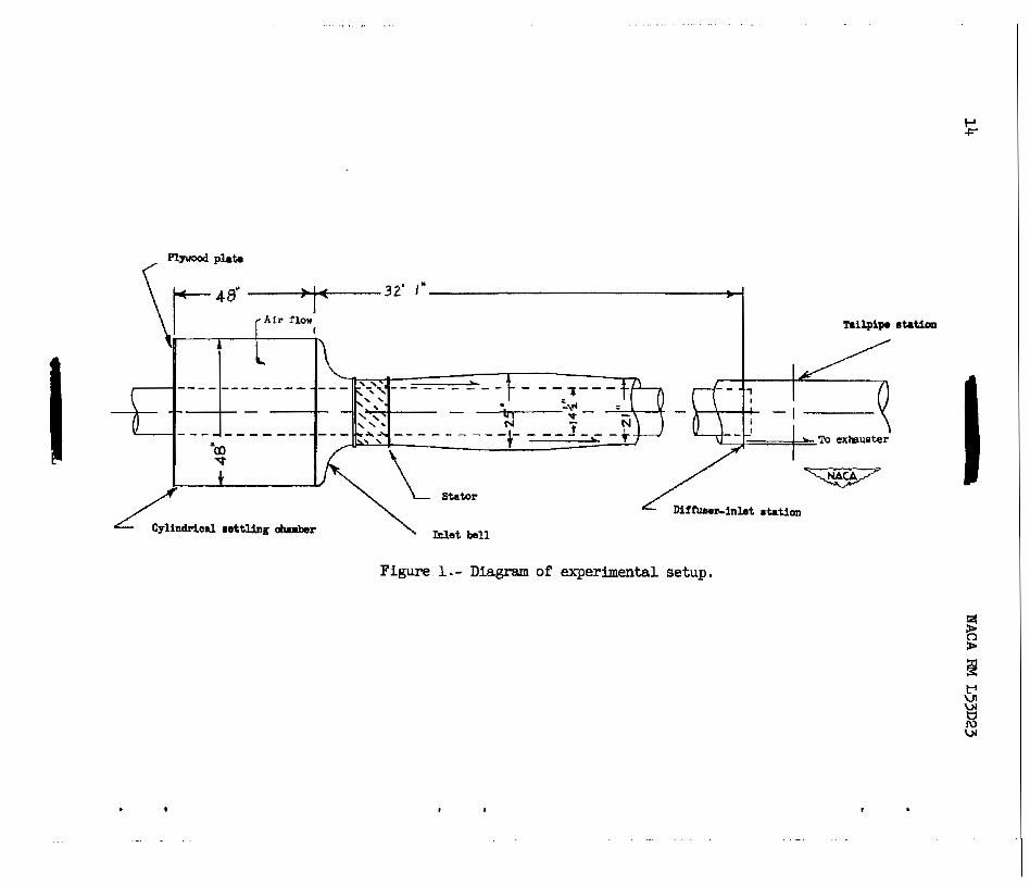
A diagram of the experbental setup is sham in f i gu re 1. A more detailed diagram of the immediate area of the difflrser is sham i n figure 2.
The setup consisted of an annular diffuser and t a i lp ipe of constant outer diameter preceded by a section of annular ducting approximately 27 f e e t long. The diffuser had an outer dfameter of 21 inches, an area r a t i o of l .g : l , and a 180° over-all equivalent conical angle of expan- sion. The upstream snnulsr ducting had a constant inner diameter of
inches and an outer diameter of 21 and 25 inches. All internal sur- 2
faces for several f e e t upstream of the diffuser inlet were f i l l e d and polished. Air entered the test apparatus through a 48-inch-diameter, 48-inch-long cylindrical chamber which was covered v l th c lo th mesh. From this chamber air f la red through a 48-fsch-dismeter i n l e t b e l l , through the s ta tors which established counterclockvfse w h i r l i n g action, as seen facing upstream, and through 27 f e e t of ann- ducting t o the di f fuser in le t . The quantity of air passing through the experimntal setup a s controlled by an exhauster connected m e r ex i t .
Inst-nktion
Stream t o t a l pressures, stat ic pressures ,
downstream of the dif -
and w h L r l angles were measured by remote-controlled survey ins t rments at both the diffuser i n l e t and ta i lpipe s ta t ions, 4 inches upstream and 22L inches down-
stream, respectively, of the end of the center body. (See f ig . 2.) These s ta t ions are identical with those of references 4 and 5 , and, therefore, permit a direct canparison of the performance of the two diffusers. A sketch of one of the survey i n s t m n t s used i n obtaining these measurements i s sham in figure 3 . Flow surveys were made at only one s ta t ion st a t h e so that there were no instruments i n t h e stream ahead of the measuring s ta t ion. These surveys were made at four positions on the circumference of the duct, at each of the survey stat ions.
2
Static orifices extending from upstream of the diff’user inlet sta- t ion t o a point 21 inches damstream of the ta i lpipe s ta t ion were installed along a single generatrix on the outer wall of the diffuser i n order that an indication of the change i n the flaw pattern with dif- fuser length could be obtained.

6 NACA RM L53D23
Small tufts were used t o observe the flow i n the diffuser. These tufts were faetened along four generatrices approximately 90° apart on the outer vall of the diffuser. The tufts could be viewed through trans- parent windars in the outer w a l l of the diffuser.
Vortex Generators
NACA 0012 airPoi ls were used both for controlling separation and for straightening the flow. Regardless of the manner i n which the air- f o f l was intended t o function, it i s referred to as a vortex generator. The angle set t ing of a vortex generator refers t o the angle the center l i n e of the vortex generator makes with the axis of the duct, When the angle between the diffuser center l ine and the vortex-generator center l i ne lays in the same quadrant as the angle between the diffuser center l i ne and the direction of flow, the angle setting is referred t o as pos- i t fve ; when the angles lay in different quadrants, the angle se t t ing i s referred t o as negative. Vortex-generator arrangements which had adja- cent generators a t the same angle se t t ing are r e fe r r ed t o as corotating arrangements; those arrangements which had adjacent generators a t oppo- site angles are referred to as counterrotating arrangements. The longi- tudinal position of the vortex generators is referred t o a plane passing through the 30-percent-chord station.
Two vortex-generator arrangements were tested; one arrangement for an inlet flow whirling a t 20.6~ and tbe other for &a1 flaw. The two vortex-generator arrangements had been used previously in tests of the l5O diffuser of reference 5 Etnd were responsible for appreciable improve- ment in diffuser performance. The arrangement used f o r axial f la r con- s i s ted of twenty-four 3-inch chord, l/2-inch-span generators set counter- ro t a t ing a t an angle setting of f l 5 O , whereas the arrangement f o r s .. whirling W e t flow consisted of twenty-four 3-inch-chord, 1--inch- Y
16 span generators set corotating a t -4'. mere configurations of refer- ence 5 are mentioned, these two arrangements are those t o which refer- ence is made. The generators were located on the Inner wall 5 inches upstream of the inner-body terminal; this position w a s several inches upstream of the location used i n tests of the 15O diffuser of refer- ences 4 and 5 . Thfs change i n location was necessary t o prevent the vortex generators from overhanging the inner wall and, consequently, resu l t ing in a serious reduction i n their effectiveness.
The description of the flow d e v e l p n t snd the effectiveness of each vortex-generator arrangement i n promoting diffusion 1s presented

NACA RM L53D23 7
- in terms of the longitudinal distributions of static-pressure coeffi- P -
- cient - pi,' the radial distributions of total-pressure coeffi-
cient Hi - - He, the static-pressure coefficient 'e - - pi, the w h i r l
angle X, and the velocity ratio u/U. The mean static-pressure coeffi- cient G/ci, the mean diffuser-loss coefficient qCi , and the m e a n flow angle at the tailpipe station are also presented.
Qci -
Qc i qci
RESULTS AND DISCUSSION
Before the flow developnent in a diffuser can be studied, the nature of the flow entering the diffuser m u s t be ham. Data from the four survey instruments spaced about the circumference at the M e t station are presented in terms of the average total-pressure coeffi- cient, the static-pressure coefficient, and the whirl angle in figure 4. Data are presented for an inlet pressure ratio 5fiia of approximately 0.95 for both axial flow and for a whirling inlet flow. Practically no variation in the distribution of the various parameters was observed with variation of inlet-pressure ratio. The inlet velocity profiles and associated boundary-layer properties at each of the four circumferential positions for the diffuser having axial inlet flaw are presented in figure 5 -
Axial Inlet Flow
Small tufts ,on the outer wall of the diffuser remained steady and axial for all tests.
Longitudinal static-pressure distributions.- In figure 6 are plots of the longitudinal distribution of static-pressure coefficient along the outer w a l l for the diffuser with and without vortex generators. Certain limited observations and conclusiona can be made from these plots, although the radial distributions (see next section) indicate these pressure rises to be higher than the m e a n pressure rise. These curves indicate gradual decreases in static pressures, beginning at the inlet s~tion and continuing damstream for approximately 16 inches, to values well below those present at the inlet station. No diffusion
approxhately the first 1/2 diameter of length dametream of the inner- body terminal. The effect of the vor%ex generators was to establish
- (pressures above those present at the inlet station) w a s realized for -

0 NACA RM L53D23
lower static pressures within the first 16 inches downstream of the inlet station and t o accelerate the rate of diffusion ccarnnencing approximately 3 inches upstream of that noted rlthout vortex generators. After about 12 t a i lp ipe diameters downstream of the inner-body terminsl, the vortex
generators result i n l i t t l e improvement in s t a t i c p re s su re . The curves realized w i t h and without generators both appear t o be approaching the theoret ical or Borda-Carnot value of static-pressure coefficient (O.w), which (see ref. 6 ) should be realized within 5 tailpipe diameters Arm the inner-body terminal.
4
The init ial decrease in s t a t i c p re s su re I s indlcatlve of an effec- t i v e flaw-area reduction or the formation of a vena contracta. The flow pattern considered responsible for the vena cmt rac t a e f f ec t is illus- trated i n figure 7. The vortex generators had l i t t l e e f fec t on the mag- nitude of the vena contracta, but did pram& an e a r l i e r and more rapid rate of mixing, as evidenced by greater static pressures, downstream fram the vena contracta. (See f i g . 6.) Downstream f'rm the vena con- tracts the rate of s ta t ic-pressure r iee per inch of ducting f o r this diffuser wfthout generators canpares favorably with that of the 15' dif - fuser without generators. If the vena contracta effect could be elimi- nated by a l t e r ing the design of the center body terminal, reasonably high static-pressure coefficients in lengths e q a d e n t t o the 1 5 O diffuser probably could be rea l lzed in the absence of the center body cone, with the advantage of an effect ive weight reduction.
Radial distributions.- Radial distributions of total pressure, s ta t ic pressure, w h i r l angle, and veloci ty ra t io a t the ta i lp ipe s ta t ion fo r the diffuser wlth and without vortex generators are sham i n f i g - ure 8. ALSO included are the distributions observed a t the diffuser i n l e t .
The distributions indicate a typical, abrupt, diffuser to t a l - pressure-loss pattern for the diffuser without flow control; that is, extremely high losses of total pressure in E large region, approximately one-half of the cross-sectional area, near the center of the diffuser. In this region a substantial decrease In s ta t ic pressure below that present near the outer w a l l is also observed. A center core, repre- senting approximately 6 percent of the area, has no measurable velocity. The flow a t the ta i lp ipe s ta t ion had a small angle of whirl which did not change appreciably across the duct.
The ef fec ts of the vortex generators on the distributions were t o decrease substantially the magnitude of total-pressure losses in the region near the duct center, to establish smal l increases in t o t a l - pressure losses in a region near the outer w a l l , t o decrease the static- pressure variation, and to increase the s ta t ic pressure across the ex i t . These changes i n t o t a l - and s ta t ic -pres~ure d i s t r ibu t ions , by the m e of

2J NACA RM L53D23 9
vortex generators, are sufficient to establish same improvement in veloc- ity profiles in the region near the center of the duct. This improvement in velocity distribution was accmplished with practically no change in u/U near the outer wall. The maximum velocity w a s reduced approximately 13 percent; this reduction indicates that vortex generators produce a more uniform velocity distribution by m o v i n g the air radial ly inward toward the center of the duct.
A comparison of the velocity distribution in the same measuring plane for the diffuser with vortex generators and for the diffuser having a l5O equivalent conical-expansion angle and no vortex generators (ref. 5) is given in figure 9 for each circumferential survey position. Although the curves for the four positions are not exactly symnetrical, they indi- cate the abrupt-diffuser-tailpfpe combination to have a more favorable distribution near the outer w a l l and less favorable distribution near the center portion of the diffuser. The velocity distributions of the two diffusers, however, are equally poor.
Mffuser performance.- The static-pressure coefficient, diffuser- loss coefficient, and w h i r l angle at the tailpipe station are presented in figure 10 as a function of the inlet-pressure ratio for the diffuser with and without vortex generators. Increasing inlet-pressure ratio has a slightly adverse effect on the diffuser performance. The reason for the slightly negative angles of whirl is not known.
Calculated values of static-pressure and diffuser-loss coefficients as obtained by the Borda-Carnot relation (see ref. 6) can be compared directly with the no-control data, and have been noted in figure 10 at a value of pJHia of 1 .OO since the relation is for incompressible flow. It has been determfned experimentslly that tailpipe lengths equivalent to about 5 tailpipe diameters are required to realize these theoretical coefficients. The measurements in this investigation were taken at a tailpipe length of about 1 diameter. It appears probable, since the total-pressure loss realized at the 1-diameter station is somewhat greater than that predicted, that the total-pressure loss between the 1- and ?-diameter stations will be of sufficient magnitude to establish over-all losses substantially greater than predicted, and that the static-pressure rise between the 1- and 5-diameter stations will be of sufficient magnitude to establish static pressures at the 5-diameter station equal to those predicted. This condition is substan- tiated by the longitudinal pressure variation given in figure 6 and the large radial variation of velocity presented in figure 8.
"
Vortex generators result in substantial increases in both the static-pressure and loss coefficients over the entire Mach number range of the test. Increases in the respective coefficients of 77 and 22 per- cent above those obtained without generators were realized. The action

10 NACA RM L53D23
of the vortex generators was not strong enough, however, to accelerate the mixing process to the point w h e r e eff ic ient di f fusion was obtained.
Data fo r compEtrison of the performance of this diffuser wi th that of an equivalent 15' diffuser are also presented i n figure 10. Measure- ments were taken a t the s= measuring s t a t ions , t k reby permitting direc t ccanparieon of resul ts . The abrupt diffuser without generators accomplishes only 23 percent of the static pressure realized for the 15' diffuser; the abrupt diffuser w i t h vortex generators acccrqplishes
of the abrupt diffuser, w i t h o r without vortex generators, is much greater than that for the 15O diffuser. It is obvious fran the stand- point of performance o r when a savlng i n weight is not highly essential that continuation of the inner body, a t least to the extent of elimi- nating the vena contracta region, w h e t h e r operating without generators or w i t h the present means of control, i s important.
percent of that rea l ized for the 15' diffuser. The 106s coefficient
Whirling I n l e t Flaw
Small tufts located on the outer w a l l of the diffuser revealed the flow on the outer w a l l t o remain attached and the whirling motion t o increase w i t h increasing distance damstream frm the in le t s ta t ion ; this condition w a s expected and noted a lso for the l 5 O diffuser of reference 5 .
Longitudinal static-pressure distributions.- In figure 11 are plots of the longitudinal outer-wall static-pressure dfstributions for the diffuser w i t h and without vortex generators. A s f o r axial flow the outer-wall static-pressure rise is greater than the mean. (See the fo l - lowing sections.) Examination of the curves indicates that minor changes in static pressure occurred upstream of the inner-body terminal, and that actual diffusion near the outer wall began only a short distance dawnstream. It i s Fmpossible t o determine w h e t h e r an actual reduction in e f f ec t ive flow area darnstream of the cercter body occurred because of the large radial pressure gradient across the duct. It appears probable that the whirling flow tended t o eliminate the vena contracta region and, consequently, t o reduce the turbulence losses associated with the flow over the sharp corner terminsting the center body; thus, the wbirling flow effect ively reduced the length of pipe required for diffusion. The e f f ec t of the vortex generators was t o e s t ab l i sh greater pressure on the outer w a l l t o t% point 10 inches downstream of the inner-body terminal and a lower pressure i n the remainder of the tailpipe.
%dial tllstributions.- Radial distributione of total pressure, s ta t ic preseure, w h i r l angle, and velocity ratio a t the tai lpipe sta- t ion for the diffuser w i t h and without vortex generators are presented in figure 12. Also included are the distributions observed a t the diffuser-inlet station.

NACA Rfii L53D23 11
Comparison of the no-control case with that of axial flow indicates that, in the region near the outer w a l l where most of the flaw was con- centrated, the whirling inlet flow produced less total-pressure loss and more static-pressure rise than axial flow. The velocity distribution is more nearly uniform than for axial flow. These resul ts are bel ieved to be due t o t h e same effect described in the preceding section; that is, the whirl ing flow near the inner w a l l i n the region of the center body terminal effectively regulates the flow darnstream of the terminal and, thus, reduces the length of the vena contracta region and the turbulence losses.
The e f fec t of the vortex generators, set a t an angle of at tack of -bo, was to eliminate the favorable effect of w h f r l along the inner w a l l by reducing the w h i r l near the center body and thus create higher to t a l - pressure loss and luwer static-pressure r ise a t the ta i lp ipe s ta t ion . The generators reduced the radial static-pressure variation and reversed the direction of w h i r l near the center of the diffuser. The changes i n t o t a l and s ta t ic pressure and i n w h i r l angle ccanbined t o produce a less favorable velocity distribution than for no control.
Comparison of the velocity distribution in the same measuring plane for the diffuser with vortex generators and f o r the 15O diffuser of ref- ence 5 having the sane vortex-generator arrangement (see f i g . 13) indi- cates that the prof i les for the abrupt diffuser are more favorable than for the l 5 O diffuser along the outer w a l l and i n a small core near the center of the duct. However , the profiles for both diffusers are poor.
Diffuser performance.- The static-pressure coefficient, diffuser- loss coefficient, and w h i r l angle a t the t a i lp ipe s ta t ion are presented in f igure 14 as a function of the inlet -pressure ra t io for the diffuser wi th and without vortex generators. The influence of inlet Mach number on the coefficients i s minor for the Mach number range investigated.
For no control a whirling inlet flow increased the static-pressure coefficient about 170 percent re la t ive to axial flow (see figs. 10 and 14) and reduced the loss coefficient about 28 percent for reasons discussed i n the previous section. Vortex generators result i n decreases and increases in the pressure and loss coefficient, respectively, when canpared with the coefficients realized without vortex generators.
CONCLUSIONS
A preliminary investigation of t h e flow properkies of a s t ra ight outer-wall, annular diffuser, tailpipe combination and the influence of vortex generators on the flow properties has been conducted fo r the purpose of obtainin5 qualitative information which might lead t o a short eff ic ient configxatioa applicable to turbojet afterburners. The diffuser has 813 -

outer-wall diameter of 21 inches, an area ratio of 1.9: 1, and a 180' over- all equivalent conical angle of expansion. The tests were conducted with a fully developed pipe flow both for an axial M e t flow and for a 20.6' whirling inlet flow. The following conclusion6 are presented:
1. For the axial-flow case, immediately downstream from the center body terminal the flow forms a vena contracts region which renders the first 1/2 diameter of tailpipe length ineffective.
2. A cmgaxison of the measured coefficients with those calculated by the Borda-Carnot relation, a relation for axial flow which has been found experimentally to apply to sudden-expansion diffusers followed by tailpipe lengths equal to 5 tailpipe diameters, indicates in the axial- flow case that, within about 1 diameter of tailpipe length, the maJor portion of the total-pressure loss has developed but only about 30 per- cent of the possible static-pressure rise has been produced because of the distortion still remaining in the velocity profile.
3. The vortex-generator installation has little effect on the nmg- nitude of the vena contracta region in the sxial-flow case and, although the installation pranotes more rapid diffusion downstream from the first 1/2 diameter of tailpipe length, the performance up to the 1-diameter station is relatively inefficient.
4. The inlet flow whirling at 20.6~ improves the static-pressure coefficient approximately 170 percent and decreases the loss coefficient about 28 percent relative to the values for axial flow. T h f s improve- ment is attributed to an apparent suppression of the vena contracta formation and a consequent reduction in the turbulence losses associated with the flow over the sharp corner terminating the center body.
5 . The installation of vortex generators straightens the flar near the inner wall and, thus, eliminates the favorable effect of rotation in this region and results in an over-& depreciation in the performance.
Langley Aeronautical Laboratory, National Advisory Cannnittee for Aeronautics.,
Langley Field, Va., April 17, 1953.

NACA RM L53D23 13
1. Nelson, William J., and Popp, Eileen G.: Performance Characterist ics of Two 6 O and Two 12' Diffusers at High Flow Rates. W A RM LgEOg , 1949
2. B o b , H., and Koppe, M.: The Influence of Frfction on Steady D i f - fuser Flows a t High Speeds. Joint Intelligence Objectives Agency (Washington), July 23, 1946.
3. Schwartz, Ira R. : Investigations of an Annular Diffuser-Fan Cumbina - t ion Handling Rotating Flow. W A F M ~ 9 ~ 2 8 , 1949.
4. Wood, Charles C.: Preliminary Investigation of the Effects of Rec- tangular Vortex Generators on the Performance of a Short 1.9:l Straight-Wall Annular Diffuser. NACA RM L51GO9, 1951.
5. Wood, Charles C., and Higginbotham, James T.: The Influence of Vor- tex Generators on the Performance of a Short 1.9:l Straight-Wall Annular Diffuser With a Whirling M e t Flow. NACA RM L52LOla, 1953
6. Gibson, A. H. : On the Flow of Water Through Pipes and Passages Having Converging o r Diverging Boundaries. Proc. Roy. SOC . (London), se r . A, vol. 83, no. 563, Mar. 2, 1910, pp. 366-378.
7. Gibson, A. H.: On the Resistance t o Flow of Water Through Pipes or Passages Havlng Divergent Boundaries. T r a n s . Roy. SOC. Edinburgh, vol. 48, pa r t I, no. 2, 1911, pp. 97-U3.
I
. .. .
Figure 1.- Diagram of experimental setup.

F i W E 2.- Diagram of the diffuser tested. All dimensions are i n inches.

16 NACA RM L53D23
Figure 3 . - Sketch of a typical survey instrument.

. .
*
P
Inlet angle of whir l a 0 6
20.6'
M
- 1 2 3
Fiwre 4.- Radial variations of total-pressure coefficient, static- pressure coefficient, and whirl ansle at the diffuser inlet for two inlet-whirl m e a . Fi/Tfh 2 o .95. -1
P

.- L3 .%
.4
0
l" t
6.0.096 0 = .087
6% =I. IO3
"_ 5==
5 .6 .7 .8 .9 1.0, Ratio of local velocity to peak velocity,u/U
Figure 3.- Velocity profilee at four equal9 spaced sections around the diffuser-idet 5tatim1. = o ; z o .95.

Tnnsr "11
7

h I \ */II \
I / "
,,,, /,//,/,,
Figure 7.- Apparent flow pattern for the diffueer with axla1 flow. All dimensions are i n inches.
. . . . . . . . .

. . . . . . .
-2- 0 2 1 6 6 1 0
. 3 t
0
-5 I I I 0 1 2 7
o r
0 2 4 6 8 1 0
Figure 8.- Radial variation of total-pressure coefficient, static- pressure coefficient, whirl m e , and velocity ratio for the diffuser with no c o n e l and with vortex generators for control. is, = 0’; - Pi&a x 0 -95 -
. . . . . .

0 -
.2 -
.4 -
( .6
I -0 i
1.OL 0 2
I 'p
;kf, I , I
b 6 8
d
"" With vortex generators
P
0 2 4 6 8 0 2 4
M@tenaa f m m outer d l , in.
6 8 0 2 b
Figure 9.- Velocity profiles at the four circumferential s w e y positions at the tail pipe station. Fl = 0'; ;i/iik =: 0.95.
6 8

1.00 -96 .92 1.w -96 l.w .96 -92
Fiwre 10.- Variation of static-pressure coefficient, diffuser-loss coefficient, and whirl angle with inlet pressure ratio. Fl = 0'.
I
10 w
. .

-No control ---D-With m r t e x generators I
a 0 2 3

-2 0 2 4 6 9 l U
. . . . . . .
0 2 4 6 ' J L C
Diatanct h outer d l , In.
.5
.7
.d
I .o o ~ 4 6 8 1 a
Figure 12.- Radial variation of total-pressure coefficient, statlc- pressure coefficient, whirl angle, and velocity ratio for the diffuser with no control and with vortex generators for control. Ti = 20.60; &&* 0.95 -

. .
With m r t e x generators
diPfuser of reference 5 - " D - - & I o d i f l
i ' P
. . . . . . . .

1.M) .96 m92
0 15' dlffuser of reference 5 0 180' diffuser
No control - - - -With vortex generators
.. . . ,
1.00 .96 -92
. .

. .
R i " . 'i' I
Y
CON Fi DENTIN