research memorandum - digital library/67531/metadc58634/m2/1/high...copy y$ r&l l5q27. -..—...
TRANSCRIPT

copy y$
R&l L5q27. -..—
RESEARCH MEMORANDUM
STABIIJTY AND CONTROL CHARACTERISTICS&
A ~ -SCALEi ELL X-5 AIRPLANE MODELr
IN THE P ING CONFIGURATION
,
ljlyRobert E. Becht
Langley :Aeronauti.cal LaboratoryLangley Air Force Base, Va.
Wm?E’m!$~U261FI=DDa’inAiri-r
(IF
Umtmmm
Q& 29s a?%...
NATIONAL ADVISORY COMMITTEEFOR AERONAUTICS
WASHINGTON
.—
—
___

TECHLIBRARYKAFB,NM
NACA RM L50J27 CONFIDENTIAL
Illlllllllillllllllliillllllllllllll‘-lli43755” .-
NA’TIONALmISORY COMMITTEE FOR AERONAUTICS
RESEARCH MEMORANDUM
STABILITY AND CONTROL CHARACTERISTICS
REU X-5 AIRPLANE MODEL
IN THE LANDING CONFIGURATION
By Robert E. Becht
OF
An investigation was1acteristics of a - - sc~ek
made of the static stability and control char-
model of a preliminary Bell X-5 airplane design-
in the landing corifigurationwith and without dive brakes. The changesin trim produced in goi!lgfrom the clean to the landing configuration
* would necessitate the use ‘ofa ccm?pensatingelevator deflection of about-5.7. Adequate elevator effectiveness was available to trim to themaximum lift coefficients attainable in the landing configuration. Theuse of plug-type fuselage dive brakes caused an unstable stall,,but thiscondition could be corrected by use of a small wing spoiler. On theother hand, flap-type fuselage dive brakes produced a stable stall, andalso a general reduction in longitudinal stability over the lLbL-coefficient range @th slight instability at the intermediate lift coef-ficients of botli20° and 66°
An investigation of the.
wing sweep ‘~es. .-
IN’’I!ROlXJCTION
static stability and control
.
characteristics
at low speed of a ~ -scale model of a prelimina~ Bell X-5 airplane design4
has been conducted in the Langley 300 MPH 7- by 10-foot tunnel. TheBell X-5 airplane is a proposed research airplane whose sweepback anglecan be varied continuously between 20° and 60°. Provision for longi.tudinal translation of the wing with respect to the fuselage is also made.
.
u
The results of thecontrol characteristicspresented in references
previous investigations of the stability andof the %11 X-5 airylane model at low speed are1 to 3. The pr&ent paper contains the results
CONFIDENTIAL

2 colmIDENrIAL mm m L50J27● -
of an investigation of the stability and control characteristics of themodel in the lading configuration with dive brakes retracted and extende~
.
The resultsthrough the
of exploratory tests made to determine the effect offuselage at the wing root are also Included.
SYMBOLS
Thepositive
CL
Cx
%
c~
cm
Cn
x
Y
z
L
M
1’.
!l
s
F
~50cl
c
system of-axes employed, together with an indication offorces, moments, ‘&d-an&les~ is presented in fi~e 1.
lift coefficient (Lift/qS)
longitudinal-force coefficient (X/qS)
lateral-force coefficient (Y/qS)
rolling-moment coefficient (L/qSb)
pitching-moment coefficient (M/qSc~)
-moment coefficient (N/qm)P--.
longitudinal force along X-ads, pounds
leakage
the
—
w “-—
lateral force along Y-axis, pounds
force along Z-axis, pounds (Lift =-Z)
rolling moment about X-axis, foot-pouuds
pitching moment-about Y-axis, foot-pounds
yawing moment about Z-axis, foot-pounds. . .
free-stream dynamic pressure, pounds per square foot (pV2/2)
wing area, square feet
wing mean aerodynamic chord (based on plan forms shown infig. 2), feet
mean aerodynamic chord at W“ sweep, feet
streamwise wing chord, feetu
wing chord perpendicular to quarter-chord line-of unsweyt @rig, “feet
CONFIDENTIAL —

NACA RM L50J27 CONFIDENT 3
wing span, feet
free-stream velocity, feet per second
aspect ratio (b2/S)
mass density of air, slugs per cubic foot
angle of attack of thrust line, degrees
angle of yaw, degrees
angle of incidence of stabilizer with respect to thrust line,degrees
control-surface deflection measured in a plane perpendicularto hinge line, degrees
A angle of sweepbackdegrees
Subscripts:
e elevator
f flap
of quarter-chord line of unswept wing,
‘+ denotes partial derivative of
( )
ti~yaw example: Cz$ =’F
a coefficient with respect to
JWPARATUSAND MEIEODS
Description of Model
The model Used in this investigation ~S a ~-scale model of a
preU~~rY *U X-5 airplane design and must, therefore, be consideredonly qualitatively representative of the Bell X-5 airplane.
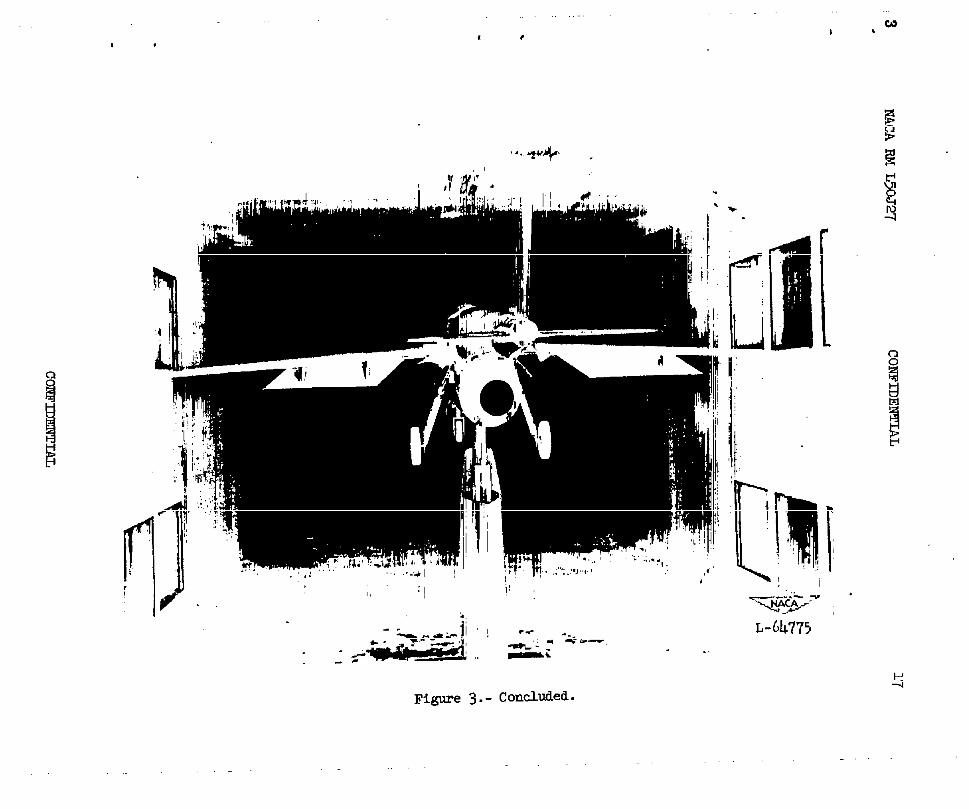
Physical characteristics of the basic model are presented in fig-ure 2 and photographs of the model on the support strut are given infigure 3. Figure 4 presents the details of the landing gears and doors.and figure 5, the details of the flaps and slats as used in this investi-‘gationo The details of the plug-type and the flap-type fuselage divebrakes are given in figure 6 along with a sketch of the gap at the wingw
CONFIDENTIAL

—
4 confidential NACA RM L5a27.
root. Details of the wing spoiler as used in this investigation are alsogiven in this figure. / -. .- 4.
The wings were pivoted about axes normal to the wing chord planes...T
The wing incidence measured in a streamwise direction yas zero for allsweep angles. At all sweep angles, the wing was located so the quarterchord of the mean aerodynamic chord fell at a fixed fuselage station.The moment reference center was located at this same fuselage station.(See fig. 2.)
The jet-engine ductingwas simulated on the model_by the use of anopen tube having an inside diameter equal to that of the jet efit andextending from the nose to the jet exit.
Tests
The tests were conducted in the Langley 300 MPH 7- by lo-foot tunnelat a dynamic pressure of 34.15 pounds per square foot whit
(?corresponds
to a Mach number of 0.152 and a Reynolds number of 2 x 10 based on the“ mean aerodynamic chord of the wing at 50° sweep for average test conditions.
During the tests, no control was.imposed on the flow quantity throughthe jet duct. Measurement= of the flow quantity indicated that the inlet-velocity ratio varied between 0.78 and 0.86, the higher values beingobserved at low angles of attack.
v
.—
Longitudinal tests were made through the single-of-attackrange byo
utilizing three tail configurations, tail off and tail incidence of -2
and -5°.
Two types of tests were employed for”detemnining the lateral char-acteristics of the model. The parameters, %# %9> and %* ‘ere
determined from test+ through the angle-of-attack range at yaw anglesof 0° and 5°. The lateral .characteridics were also determined from
,
tests through a range of yaw angles at cmst=t..angle of attack, —.
Corrections
The angle-of-attack, drag) ad pittiing-moment results have beencorrected for jet-boundary effects computed on the basis of unsweptwings by the methods of reference 4. Indep&ident calculation have
shown that the effects of sweep on these corrections are negligible.All coefficients have been corrected for blocking by the model and itswake by the method of reference 5.
coNFIDmIAIl
—
. .

NACA RM L50J27 commtuu 5.
Corrections for the tare forces and moments produced by the support. strut have not been applied. It is probable, however, that,the signifi-
cant tare corrections would be limited to small increments in pitchingmoment and drag.
Vertical buoyancy onand longitudinal-pressureof the test data.
the support strut, tunnel air-flow misalinementgradient have been accounted for in computation
RESULTS AND DISCUSSION
Presentation of Results
The longitudinal aerodynamic characteristics of the model with20° wing swee~ having both slats and flaps retracted and extended arepresented in figures 7 and 8, respectively. These data were obtainedfrom retests of the model to allow for comparison with the aerodynamiccharacteristics of the model in the various configurations to follow.The original data for these configurations, as given ti references 1
b, and 3, were not used inasmuch as the wing of the test model tis refinished
at the conclusion of the investigation reported in reference 3. Closeagreement, however, was obtained with the data presented in reference 34 and reference 1 for the same model configurations.
The principal results of the imestigation are presentedas follows:
Figures
Effect of landing gear and gear doors:Longitudinal Characteristics . . . . . . . . . . . . . . . ..9to12 “Longitudinal control. . . . . . . . . . . . . . . . . . . . . . . 13Lateral and directional characteristics . . . .. . . . . . . . . 14
Effect of dive brakes:Longitudinal characteristics . . . . . . . . . . . . . . . . .15 to 19Lateraland directional characteristics . . . . . . . . . . . . . 20
Effect of air gap around wing root:Longitudinal characteristics . . . . . . . . . . . . . . . ... . . 21Lateral and directional characteristics . . . . . . . . . . . . . 22
The aerodynamic coefficients presented herein are based on the wingarea and span of the sweep configuration in question and on the mean aero-
. xc chord of the wing at ~“ sweep. Thus, the pitching-moment coef-ficients are based on a reference length which is fixed with reSpeCt tOthe fuselage ,pmdis independent of sweep angle, whereas all other coeffi-
. cients are of the usual form.
CONFIDENTIAL
.

6 NAcA m L50J27 ““‘.
The Effect of Slats, Flaps, Landing Gear, and Gear Doors.
Characteristics in pitch.- In order to-provide an index of thechange in stability, the change in trim, and the change in drag coeffi-”cient produced by the various modifications, the parameters, aCm)bCL,cm> and Cx have been evaluated at a.lift coefficient of 0.6 and are
tabulated in the fQllowing table. The elevator deflection required to-.
.-
30 tail settingis also included.trim the model at CL = 0.6 with a - ~
me lift coefficient of 0.6 was chosen as the value at which flaps, slats,and landing gear might be extended.
—
M!&-
Wm~ —
Configuration(:; &=.~) p:-,) @t?- ~) @:- ~) betrti
:lean 0.024 -0.063 -0.068 -0.042 -0.044 -4.~
‘l::e::dflap s 0.033 -0.059 -0.093 -0.082 -0.123 ------
leardown anddoors on
0.019 -0.042 -0.047 -0.048 -0.077 ------
leardown anddoors off
0.035 -0.063 -0.073 -0.052 , -0.077 ------
Lats and flapsextended, geardown and doors 0.028 -0.066 -0.071 -0.084 -0.160 -10.2on (landingconfiguration)
,latsand flapsextended, geardown, doors
0.042 -0.074 -0.om -0.092 -o.~56 ------
off
The landing configuration is defined as slats extended, flaps defle=+ed; .
lading gear down, and gear doors left on.
.
CONFIDENTIAL
.

I?ACARM L50J27 CONFIDENTIAL
It can be seen in the preceding tableencountered in going from the clean to theno greater than 3 percent am ● The model
7.
that the stability changeslanding configuration wereeihibited the least stability
with slats and flaps retract&d, landing gear extended, and gear doorsleft on.
A nose-down trim change was experienced in all intemuediate con-figurations leading to and including the landing configuration regardlessof whether slats and flaps were deflected first or last. The landingconfiguration had a increase in drag coefficient of about 0.116 overthat of the clean model. Of this dxag increase, about 0.079 was due toextending the slats and flaps. The lift-curve slope at CL = 0.6remained essentially constant for all tail-on configurations listed inthe preceding table and had a mean value of 0.085.
Longitudinal control.- The effect of elevator deflection on thelongitudinal aerodynamic characteristics of the model is presented infigure 13. The elevator deflection required to trim the test model at
a lift coefficient of 0.6 with a stabilizer setting of - $0 is listed
in the preceding table as -4.5° for the clean configuration andThe data required to compute the-%ofor the landing configuration.
elevator deflection of the clean configuration was obtained from refer-ence 1. It was noted that adequate el&rator effectiveness was availableto trim the model over the lift coefficients obtainable in eitherconfiguration.
Characteristics in yaw.- Figure 14 shows that the directionalstability of the clean model was essentially constant through the lift-coefficient range up to about
C%ax”The use of slats and flaps extended -
the stability to higher lift coefficients because of the increased maximumlift attainable. Directional instability was experienced after or very
‘ear ‘he Ckxof the model configuration in question. b general, good
agreement was obtained with the data presented in reference 2 for theclean model and for the configuration utilizing slats and flaps. Extendingthe landing gear and leaving the gear doors open resulted in a decrease indirectional stability from that of the configu=tion with slats and flapsextended althou@ this decrease became less evident at high liftcoefficients.
The effective tiedral of the clean model was increasedby a fairlyconstant amount through the lift-coefficient range when slats ~d flapswere used. The extended landing gear and the open gear doors, however,
. tended to nullify this increase.
.
.CONFIDENTIAL

8 CONFIDENTIAL
The Effect of Dive Brakes
Characteristics in pitch.- Althou@ the effect of thebrakes on the stability”characteristics of the clean model
.,.—.
mcA m L5w27-“
.
..”.
plug-type dive -was satis-’ -—
.factory (see reference-3), figure 15 shows that an unstable stall isexperienced if this type brake is used in conjunction “withthe landingconfiguration. Inasmuch as the unstable stall is evidenced in the tail-off pitching-moment curve, it can be assumed that the tail did not con-tribute significantly to this instability. In attempting to determinethe cause of the unstable stall, tests were made with the rear landing-gear doors removed to simulate-their being closed after the gear was down.The results presented ‘infig@e 16 indicate that the rear landing-geardoors did not contribute fundamentally to the instability at the stall.As a means of evaluating the effect of the rear doors without the divebrakes, tests were made of this configuration and the results are presentedin figure 17. .
With the tail and the rear landing-gear doors eliminated as theprimary cause of the unstable stall of the model In the landing con-figuration with dive brakes extended, tuft studies of the flow on thewing were made. With dive brakes extended,.% appreciihle section ofthe wing inboard riearthe wing-fuselage juncture remained unstalled after a
flow separation of the rest of the wing was fairly complete. By inducinga premature separation in this region with R small spoiler located asshown in figure 6, a stable stall could be obtained. (See fig. 18.) In ‘.addition to the stable sta~, some increase in longitudinal stabilityand drag was realized over the configurationwithout the spoiler.
If the plug-type Mve-%rake design were changed to that of the flaytype having approximately the same frontal area, the flap-type dive brakewould provide higher drag than that of the plug-type dive brake andspoiler. (See fig. 18.) A somewhat reduced stability resulting inslight instability above .CL = 0.9 was obtained for the center-of-gravity
—
and wing locations assumed. A stable stall, however, was experienced.
In view of the stable stall at 20° wing sweep, the effect of theflap-type dive brakes at 600 wing sweep was considered of interest.Figure 19 shows that a reduction in longitudinal stability was againobtained with very slight instability occurring near a lift coefficientof 0.7 when the flap-type dive -brakeswere used on the clean configurationwith a 600 swept wing. At CL = 0.8, stability was again evident up to
and beyond the stall. The mximum lift coefficient as well as the lift-curve slope was reduced when the flap-type bz%lseswere used. The dragcoefficients at low lif’tcoefficients were increased about 0.025 overthose of the clean model. .
Characteristics in yaw.- In view of the almost nonexistent effectof the plug-type dive brakes on the lateral-stabilityparameters of the w“”
clean configuration with 20° wing sweep,(reference 3), tests of the —
CONFIIIENTIAL

2 NACA RM L50J27 CONFIDENTIAL 9.
.
.
flap-type dive brakes on this configuration were not undertaken. Whenthe flap-type dive brakes were used on the clesm configuration with60° sweep, an appreciable reduction in directional stability in themoderate lift-coefficient range was observed. (See fig. 20.) Directionalinstability occurred at a lift coefficient 0.17 below C
kcompared to
instability at a lift coefficient 0.23 below C&x for ~he clean model
configuration. The instability of the model with dive .brakesoccurred,however, at a lower lift coefficient because of a reduction in C
%ax”Increases in the effective dihedral of varying magnitudes up to stallwere observed when flap-type dive brakes were used, and, at the stall,values less negative than those of the clean configuration were encountered.
Effect of Gap at Wing Root
Characteristics in pitch.- The contemplated Bell X-5 airplane designincludes a sliding fillet arrangement at the wing root that translatesalong the outside of the fuselage in conjunction-with the wing. -Asameans of evaluating the effect of leakage through the fuselage at thewing root of the configuration with 20° wing sweep with slats and flapsextended, a few exploratory tests were made with a gap of roughly 1/2 incharound the wing root as shown in figure 6. This gap should produce muchmore extreme leakage than would be anticipated on the full-scale airplaneand its effect on the test model would more than likely represent theouter boundary of the effect on the full-scale airplane. “The over-alleffect of the gap on the test model was what might be expected from theuse of a wing of lower asyect ratio. The increase in longitudinal sta-bility of the model with the gap open indicated an outward and rearwardshift in the aerodynamic center due to unloading at the wing.root (fig. 21).Although no tall-off tests were made, some reduction in downwash at thetail may have contributed to the longitudinal-stability increase. Thelift-curve slope was reduced and the increase in drag became greater withincreasing lift coefficient.
Chaza,cteristicsin yaw.- The directional stability was again fairlyconstant with lift coefficient with some slight decrease noted over thatof the configuration having the gap closed (fig. 22). The effective-dihedxal variation with lift coefficient followed essentially the sametrends as observed with the gap closed only with some slight decreasesparticularly in the high lift-coefficient range.
.
CONCLUSIONS
An investigation of the static stability and
at low speed of a ~- scale model of a preliminary4
CONFIDENTIAL
control characteristics
Bell X-5 airplane

-.
10 CONFIDENTIAL NACA RM L50J27
design in the landing configuration has been conducted and the followingconclusions have been drawn: .
1. Changes in trim produced in going from the clean to the lamtingconfiguration would necessitate the use of a compensating elevatordeflection of.about -5.7°. The longitudinal-stability changes encounteredin going to the landing configuration were no greater than 3 percent ofthe mean aerodynamd.cchord at 50° sweep.
--
2. Adequate elevator effectiveness was available to trim to themaximum lift coefficients attainable in the landing configuration.
3. The use of plug-type fuselage dive brakes Cauged an unstable ..” ..— “- .stall in the landlng configuration but a stable stall could be obtainedby addition of a small wing spoiler.
k. The use of flap-t~e fuselage dive brakes produced a stable stall,and also a general reduction in longitudinal stability over the lift-coefficient range tith slight instability at the intermediate lift coef-ficients for both the 20° and 60° wing sweep angles.
5. Leakage through the fuselage at the wing root of the configuration -with 20° sweep with slats and flaps extended increased the longitudinalstability and drag and, also, reduced the lift-curve slope. b.
Langley Aeronautical LaboratoryNational Advisory Committee for Aeronautics
Langley Air Force Base, Va..-
,
.
CONFIDENTIAL

.
.
NACA w L50J27 CONFIDENTIAL 11
REFERENCES
1. Kemp, William B., Jr., Becht, Robert E., and Few, Albert G., Jr.:
Stability and Control Characteristics at Low Speed of a ~-Scale
BelJ X-5 Airplane Model. Longitudinal Stability and Control.NACA RM L9K08, 1950.
2. Kemp, William B., Jr., and Becht, Robert E.: Stability =d Control
Characteristics at Low Speed of a ~-4
Scale BellX-5 Airplane Model.
Lateral and Directional Stability and Control. NACA FM L50C17a,1950.
3. Becht, Robert E.j and Few, Albert G., Jr.: Stability Characteristics
at Low Speed of a l-Scale Bell X-5 Airplane Model with VariousF
Modifications to the I!asicModel Configuration. NACA RM L50F23,1950.
4. Gillis, Clarence L., Polhamus, Edward C., and Gray, Joseph L., Jr.:Charts for Determining Jet-Boundary Corrections for Complete Modelsin 7- by 10-Foot Closed Rectangular Wind Tunnels. NACA ARR L5G31,1945.
5. Herriot, John G.: Blockage Corrections for Three-Dimensional-FlowClosed-Throat Wind Tunnels, with Consideration of the Effect ofCompressibility. WCA RMA7B28, 1947.
.
.
CONFIDENTIAL

—u.. . CONFIDENTIAL NACA RM L50J27
.
.—
x
E
Reiotive wind
*-
.——
*
.. . ..-
. .- .r—
.-
Vi”ewA-A
Figure l.- System of axes andvalues of forces, moments,
control-surface deflections. Positiveand angles are indicated by arrows.
.
“.--. —.
coNFmw —.

NACA RM L50J27 CONFIDENTIAL 13.
.
w“.558 I
a?
49
..
PRYSICAL C~ISTIS
ui~.Sweep,deg.....hen, aq ft . . .,. 10.: 10.?; 10.% 11.:Aspect ratio . . . . 5.76 4.% 2.93 1.92Span,ft...... 7.72 6.90 5.67 4.66”Keen aerodynm.fc
ChOrd, ft.... 1.3961.579 1.985 2.5%Incidmce, deg . . . . . . . . . . . . .Dihedral, deg..... . . . . . ...-2Airfoil sectlm perwndia.ilOr to 0. ~c:
Root . . . . . . . . . . WA &q~o)-O1O. 3Tip . . . . . . . . . . . . . HACA6bO08
Eorizontd tan:kea, nq ft . . . . . . . . . . ...1.94hpect ratio . . . . . . . . . . ...2.89
Vertical tail:Area,sift ......... . ...1.33Aspect r8ti0 . . . . . . . . . . ...1.116
Figure 2.. General arrangement of test model.
corTmmN’rIAL

I
________
unSW.2pt wing
1
0 .?0~
Scafe, imhes
1- —-
-~-—-
~ feuding ed~’of fillet swept
53” for WI wing SWeeps.
v
M-=1675
‘ ‘ 20”
y
\bJ.,.
‘Lo;-_ ,......,
,, .,, ,,,
I
j! I
i ,
1
C*’
“1 ,,’1 ‘,

1 i ,
Figure 3.. Views of test model mounted in tunnel.

.
.-
.●
✎�
.
.
.
‘ rw
, ,
,
“,++ .
/’.-.
..
I
ii
i
y’ pj .,,’”,. -,’4
1!
,.,<”
..,- .-: . -’r---
=i
U!l
.->.
L-~4775
.
(!oncluded.

,. .
.
.
.
.

.
.
.
NACA RM L50J27 CONFIDtiIAL19
Nose-gear door angular dispbcement 90°
4.00
2A’
Elevation projection of bndinggeor doors.DOOrS flush in closed posifionj angulardisplocemenrs for full open positions ore: ‘forward door 39°aft door 550
=!s=’
‘ o~,o
Scale, inches
Figure 4.- i)etailsof the landing gear ati doors.
coIO?mENTIAL

I-’’’’+’”-l ‘3
\
025 CM of wxwept wing
L bise&@? h? at A =20°
Fuselqe line at A =60°
T0.30C
Y
Split flap
Section A-A
Section 8-B
Fl&swe f).- Details of flap aml slat.
I
o 10-m-, ,,,qo
Scale, inches
:, 1
\ I
1,., . .,,.
,, l,’
L
~.:. \

, . . t s
&/m
qmtkr
3.30
Q-
2.30Plug dive broke
o /0 ‘?’0
Scale, inches
.—-— -—-
~ PIIKJ divebmke
.
Figure 6.- Details of dive brakeB, air gap, and spoiler.
I
I

.
22
24
20
-4
CONFIDENTIAL NACA FM L’jOJ2T.
t-t o- ‘%4 tt+-1
—...
. .
-$ 22 0 .2 4 .6 .8 /.0
Lift coefficient CL .
Figure 7.- The effect of tail incidence on the aeromc characteristics .of the test model. A = 20°; slats retracted; Bf”= O“j landing gear andgear doors off.
NACA RM L50J27 CONFIDENTIAL 23
.
.
8
‘
.
I I I I I I ! I I I~?..
1
I I I , I ps%I I I I I t I
o .2 # ●6 .8 /.0 i2 /.4 /.6 18~iff ~fficien~, CL
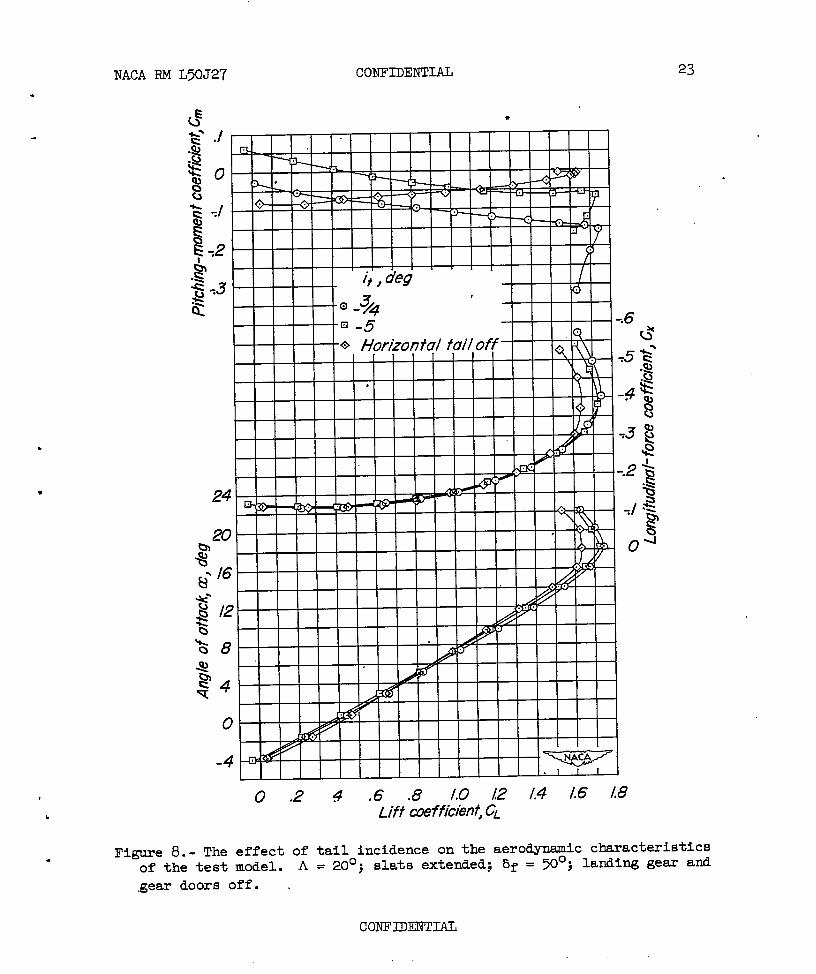
Figure 8.- The effect of tail incidence on the aerodynamic characteristicsof the test model. A = 20°; slats extended; bf = ~“; landing gesx and
gear doors off. .

------
24 CONFIDENTIAL NACA
24
20
-4
●
-4 :2 0 .2 4 .6 .8 10Lift coefficient CL
RM L50J27
:gure 9.- The effect of tail incidence on the aerodynamic charactof the test model. A = 20°; slats retracted; bf = OO; landingextended and gear doors open.
—,
ieristicsgear
..
.
.

4.
NACA RM L50J27 CONFIDENTIAL
.
I w I
I 1 I I I I I
! I I I I I
1 I I
~, degI I IL
20
$ /6
o
-4
-4 :20.2~.6”8~0h’fi ~f?%cient,CL
25
.
.
characteristicsFigure 10.- The effect of tail incidence on the aerodyn@cof the test model. A = 20°; slats retracted; bf = O ; landing gear
extended and gear doors off. ‘
co~nmw ,

24
-&4
o
-4
RM L50J27
.
.
.- .”:.
-.6
0 .2 4 .6 .8 /.0 L2 L4 Lt5 /.8Lift coefficient CL
Figure 11.- The effect of tail incidence on the aerodynamic characteristicsof the test model. A= 20°; slats extended; bf = 50°; landi~ gear
extended and gear doors open.
●
✎
—.
coNFmI#iL

.
NACA
Figure
RM L’X)J2T CONFIDENTIAL
24
20
@ /6
JQ4s?
‘o
-4
o .2 g .6 .8 /.0 /2 /.4 /.6 lw8~ift coefficient, c’
12.- The effect of tail incidence on the
27
.
of the test model, A = 20”j slats extended;
extended and gear doors off.
CONFIDENTIAL
aerodynamic characteristics13f= ~“; landing gear

—
28 CONFIDENTIAL NACA RM L50J27
I
.gS-.z
“$
24
20
:4
0- n
1 1
II 1 1
i
I I 1 1 1 I I 1 f 1 1 I
1
.-
.
.
.—.—
,-
.—
-
.,
-.6Q*
0 .2 4 .6 .8 10 /2 /,4 /6 /8Lift cmfficient, CL
Figure 13. - The effect of elevator deflection on-the aeromic character-
istics of the test model. A = 20°; slats extended; ~f”= no; landinggear extended and gear doors open.
-.
..
—
*
..
—
.-.,:
coITFIIENTm

NACA RM L50J27*
CONFIDENW 29
.
Lift wefticiem’, CL
Figure 14.- The effect of slats and flaps, and the landing configurationon the lateral-stability parameters of the clean model. A = 20°.
coI’w’IDmIAL

30
o .2 4 .6 .8 loLift aeffichnt,~
Figure 15.- The effect of’tail incidence on theof the test model. A = 20°; slats extended;‘extended; gear doors open and plug-t= dive
CONFDENTW
—
J27=
——
.
.—
.
.
.
—
aeroQmamic.characteristic6bf = 50°; landing gem a
L -.brakes extended.

NACA RM L50J27 CONFIDENTIAL 31
s
—,o .2 4 .6 .8 10 /2 /,4 /.6 /8
Lift coefficient,c’
.
Figure 16. - The effect of the rear landing-gear doors on the aerodynamic
characteristics of the test model. A= 3°20°; it = -q ; slats extended;
Gf = X“; landing gear extended; nose wheel doors and front main gear
doors open; and plug-type dive.brake extended..
COIW’lDENT121L

32 CONFIDENTIAL I -- NACA RM L50J27
.UE2’“s?
.—
24 a.fi # , 1 1 1 I 1 t 1 , , , , t 1
o .2- 4 .6 .8 10 /2 /.4 /.6 /8
0
—
Figure 17. - The effect of
characteristics of the
af . ~“; landing gear
Liffcoeffici?nf,c,
the rear landing-gear doors on the aerodynamic
test model. A = 200; it = 3°- ~ ; slats extended; _
extended; nose wheel doors and front main gew”
doors open; plug-type dive brakes off.
#
—.. --.
..-
. .
.,
.
.a..–
,-.--.:.-
CONFIDEMTIAL ..

5.
.
NACA RM L50J27 . CONFIDENTIAL 33
1 1
I
‘l-
1
I I
-4 WI I I 1 I I
‘O .2 4 .6 .8 /.0 12 /.4 /.6 18Lift coefficient,CL
o
Figure 18. - The effect of dive brakes on the aerodynamic characteristics
of the test model. A= 20°; it = -:O; slats extended; bf = m“;
landing gear extended; and gesr doors open.
coNIKtOENTIAIl

34 CONFIDENTIAL .NACA RM L50J27’
36
32
28
4
0
-4.
I
I
.
72 0 .2 4 ..6.8 10 !2 /.4Lift cMfficient)CL
..
.
.
. ..
Figure 19. - The effect of the flap-t~e dive brakes on the aerodynamic
3°characteristics of the clean model. A = @; it = - - .4
colwumv’TIAL >. --,-.

NACA RM L50J27 CONFIDENTIAL
.
.
78u“
\\.7\&.6
o:2 0 .2 4 96 .8 /.0 [2 /.4
Liftcoefficient,CL
Figure 19. - Concluded.
coNFIDmm

36 CONT’IDENTIAL NACA RM L50J27.
.0/4
.0/2
.0/0
.009
.aw
.004?002
0
-.002
.004
a%
.004
.W2
o
.002
-.004
-.026
.
L
/‘4
0 Ckw7 cohfiuumtion
[
, , ,, ,E Flap-type dive brakes extended II I
I I I I I I !HI 1“1
. .—
.-
;2 O .2 4 .6 .8 10 /!2 /.4Lift awffkien~ G“
. —
Figure 20. - The effect of the flap-t~e dive brakes on the lateral.
sostability characteristics of the clean model. A = 6U”; it = - - .
4
CONFIDENTIAL .-A

NACA RM L50J27 CONFIDENTIAL 37
*
●
.
.
24
20
o
-4
0 .2 4 .6 .8 LO L2 /.4 /.6 18Lift coefficie/?(CL
-.6(,$*
4
0
-*
Figure 21.- The effect of the air gap in the fuselage on the aerodynamiccharacteristics of the test model. A = 20°; slats extended; bf = 50°. ●
coNFIDENm

!
38
.—. , . .—-..- -.
CONFIDENTIAL.
—
—~ NACA RM L50J27
-.
.--
0 .2 $ .6 .8 /.0 12 /,4 /.6 18Lf’ff coefficient G’
.02cYfi
o
Figure 22. - The effect of the air gap “inthe ““fuselageO% the latera,l-
stability parameters of t~ test model. A = 20°; it-= - So; slata4
extended; &f = ~“.
.
b
,
*
.
.
●
NACA-Langley -12-18-50 -900