,research memorandum/67531/metadc63682/m2/1/high_res… · autopilot, and an airplane are...
TRANSCRIPT

,RESEARCH MEMORANDUM , ,
. ,
ANALOG COMPUTER STUDY O F SOME FILTERING, COMMAND-COMPUTER,
SUPERSONlC INTERCEPTOR
By Windsor L. Sherman

NACA RM L57G23
NATIONAL ADVISORY COMMITTEE FOR AERONAUTICS
RESMCH MEMORANDUM
ANALOG COMPUTER STUDY OF SOME FIECERING, COMMAND-COMPUTER,
AND AUTOMATIC-PILOT PROBW CONNECTED WITH THE ATI'ACK
PHASE OF THE AUTOMATICALLY CONTROLLED
SUPERSONIC INTERCEPTOR
By Windsor L. Sherman
SUMMARY
Presented herein are the resul ts of a study of some of t he problems assoc ia ted wi th the c ross - ro l l f i l t e r , command computer, and g-limiter of an automatic interceptor system. The evaluation of these components w a s made with s t ra ight-f lying targets and t a r g e t s t h a t made a k2g ver t ical- plane maneuver. The interceptor system used assumes lead-col l i s ion f i re - control computing and an armament of unguided rockets. This interceptor system i s described i n NACA RM ~ 5 6 ~ 0 8 .
The r e su l t s , which are presented as time h i s t o r i e s of the airplane and control-surface motions, show tha t c ross - ro l l cor rec t ions are most desirable when f i l t e r i n g i n a rotating coordinate system and tha t , when an inner-loop integrator i s included in the longi tudinal control system, the best operation of the command type of g-limiter i s obtained. In addi t ion , the resu l t s for the command computer show that al though the present computer provided adequate control for this s tudy, more study i s needed on the problem of roll-command computation. Also, t h e r e s u l t s f o r t h e maneuvering t a rge t i nd ica t e t ha t a high-gain longitudinal control system i s necessary when tracking a maneuvering t a r g e t .
INTRODUCTION
One means of defense,against s t ra tegic bombers i s the manned i n t e r - ceptor. A t present these interceptors are equipped with fire-control apparatus but m u s t , i n general, be flown by a p i l o t . The projected development of t h i s type,,,of.,,w.e,apons system i s t o make the a t t ack phase of the interceptor compl;e$e;li: a ,~~?~ t~~cc ' : : :~~ i : s , , , phase begins with the
I . .-, . ., :,,.\ .j)
" , ,, . . . . I , , . . . ,I . ,
;.,~ i.",'.. . I , . :,. > ,. : i . . ' - ,. . , , .',!> b , I .
-. : '.;.:; , .
I., , . . . .

2 NACA RM L57G23
airborne intercept radar lock on and ends with the firing .of the inter- ceptor armament. Reference 1 is a report of an'investigation of the flight maneuvers of an interceptor during the attack phase and of the manner in which the response of the interceptor was affected by nonlinear aerodynamics and changes in the dynamic representation of the interceptor.
In addition to the airplane and fire-control equipment, an automatic interceptor system has an error filter system, a command computer, and an automatic pilot. The method of filtering and computing and the choice of gains in these three components can and do influence the response of the interceptor. The purpose of the investigation reported herein was to study the effects of certain changes in computing and gains on the response of the interceptor described in reference 1. For this purpose the effects of cross-roll corrections in the filter system, changes in the roll-command computing, the command g-limiter, and gain changes in the longitudinal control system were studied. This study was conducted concurrently with the investigation reported in reference 1 on the typhoon computer at the U. S. Naval Air Development Center, Johnsville, Pa.
In this study the assumption was made that a Mach number 2.2 inter- ceptor executed a forward-hemisphere attack against a Mach number 1.4 target that was flying a straight-line course or making a f2g vertical- plane maneuver that started at radar lock on. Results are presented in the form of time histories obtained from an analog computer. The results illustrate the effects of the aforementioned changes. Representative results are included to show the effectiveness of the airplane-autopilot combination against the maneuvering target. Au. results presented in this paper were obtained under the basic assumption that the interceptor armament consisted of unguided rockets.
SYMBOLS
n
M - C
linear airplane velocities along the x,y, z body axes, ft/sec
angular airplane velocities about the x,y,z body axes, radians/sec
acceleration of gravity, 32.18 ft/sec 2
normal acceleration
Mach number, a v
mean aerodynamic chord
missile velocity vector with respect to airplane, ft/sec

1-
NACA RM L57G23 3
airplane velocity vector, IvI1 = {u' + v2 + w2, f t / s e c
target veloci ty vector , f t /sec
free-stream velocity of sound, f t / s ec
target accelerat ion vector , f t /sec
azimuth miss distance, f t
elevation miss distance, f t
2
range vector, f t
future range
to t a l vec to r miss distance ( M = l ( 0 ) + JM, f k&), f t -9 3 3
unsmoothed azimuth and e leva t ion s teer ing e r rors
time
time t o go, sec
Laplace transform variable
direction cosine between airplane and space vertical axes
rolling-moment coeff ic ient
pitching-moment coeff ic ient
yawing-moment coeff ic ient
l i f t c o e f f i c i e n t i n body axes
altitude, f t
transfer function f/Se of airplane
f l ight-path angular rate ( 6 - &)
transfer function q/Se of airplane , .

NACA RM L37G23
gain constants
t o t a l smoothed s teer ing error (E = ca2 + ge2)
smoothed azimuth s teer ing error , radians
smoothed elevation steering error, radians
Euler angle and airplane pitch angle
control-surface deflection, deg
angular velocity vector of l i n e of s igh t of radar, (w' = I p + Tq + &> , radians/sec
unit vectors
time of missile f l ight, sec; or control-system time constant, sec
bank angle
s idesl ip angle (p = ;), radians
rudder deflection
ai leron def lect ion
angle of a t tack (a - ;), radians
wing area
azimuth and elevation gimbal angles, radians
N e r angle and airplane yaw angle
with another symbol, indicates perturbation of attached symbol

NACA RM L57G23 5
A dot over a symbol denotes the derivative with respect to t ime.
Subscripts :
0
c r
C
d
e
f
1
s s
i nd ica t e s i n i t i a l cond i t ion or output
c r i t i c a l
command
dynamic pressure
limit value of variable
f i l t e r t i m e constant
input
l i m i t
steady state
S TMULATION AND DESCRIPTION OF THE CONTROL SYSTEM
The analog setup for the Typhoon Computer which was used i n t h i s study i s descr ibed fu l ly in re fe rence 1.
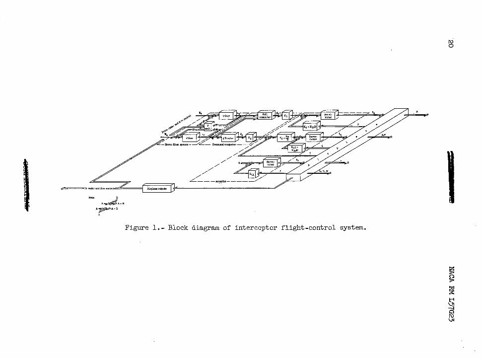
Figure 1 i s a block diagram of the f l igh t -cont ro l system, the por- t i o n of the in te rceptor sys tem cons idered in de ta i l in th i s repor t . A s ind ica ted in figure 1, an e r ror f i l t e r system, a command computer, an autopi lot , and an airplane are considered. The f i l t e r system consists of two f i r s t -o rde r f i l ters, one f o r t h e lateral command and one fo r t he longi tudinal command, with a r o l l mult ipl ier for cross-rol l correct ion. The command computer consis ts of a g- l imiter , and a rol l -order computer. Manually adjustable gains . K3 and are appl ied to the ou tput of t he roll-command computer and g-limiter before these outputs are f e d t o t h e automatic pilot .
I
6 - NACA RM L57G23
The automatic pilot provided proportional type control and had rate and acceleration feedbacks in the roll-control and flight-path-control loops, while the rudder is controlled by a yawing velocity or sideslip angular-rate feedback. The servomotors in the autopilot were represented " by first-order equations, with rate and displacement limiting added to the simulation. These autopilots were analyzed on the analog computing equip- ment at the Langley laboratory to determine their suitability for use in this study. The results of these studies are reported in references 2 and 3 .
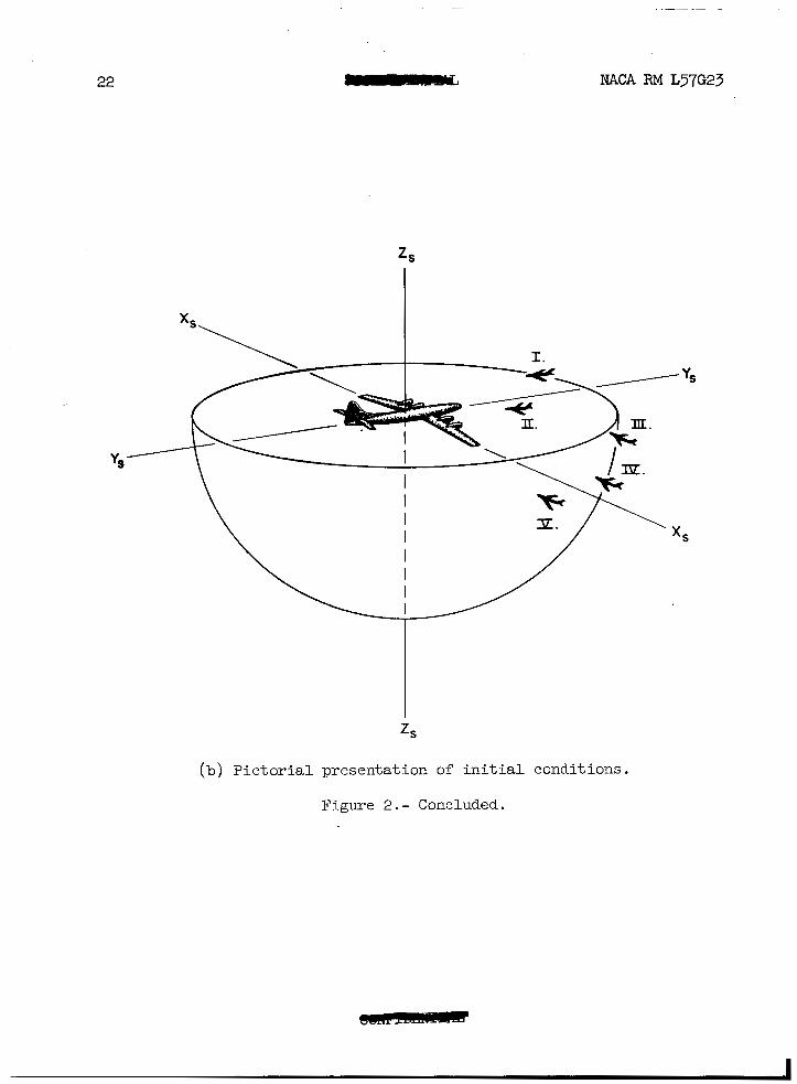
The fnterceptor used was a high-speed airplane of advanced desim. The basic aerodynamics were calculated by the use of linear theory, and the results are given in reference 4. These data were then modified, as indicated in reference 1, so that the nonlinear variations of the aero- dynamic forces and moments with angle of attack were accounted for in the simulation. Drag data and control-surface effectiveness were obtained from wind-tunnel tests. In this study the airplane was always represented by the six-degree-of-freedom equations of rigid-body motion referred to principal body axes. The same sets of initial conditions were used for the current study as were used in the study reported in reference 1. For convenience, these conditions are repeated in table I and figure 2.
The table of initial conditions contains no initial values for G, 4 - M, Rf, ea, ee, and gC. The initial value of each of these parameters is automatically determined if the values from table I are substituted in the equations of the interceptor system which are presented in appen- dix A of reference 1.
In these attack runs it was assumed that the radar had been tracking the target long enough so that the fire-control computer had completely charged the filters before commands were fed to the autopilot. Because of this assumption the following initial conditions were imposed upon the error filter system.
Ga(0) = Ea(0) ta(0) = 0 ~ ~ ( 0 ) = Ee(0) 6,(0) = 0
In addition, the servomotors following initial condition.
6,(0) = 0
for the autopilot were programmed with the
w ( 0 ) 6 , = - TS

NACA RM ~ 5 7 ~ 2 3 - 7
RESUITS AND DISCUSSION
The Cross-Roll Filter D
Because a tracking radar output consists of a t rue s ignal plus some I random-noise s igna l and because of the dynamics of t h e computers, the
information signals m u s t be smoothed before they are combined and used as s teer ing s igna ls for the a i rp lane . This smoothing or f i l t e r i n g may be appl ied to e i ther the t a rge t ve loc i ty , which under the assumptions of a f i rs t -order f i re-control system i s essent ia l ly time invariant , or t o t he ou tpu t of the f i re -cont ro l computer. In the system considered i n t h i s r e p o r t , t h e f i l t e r i n g i s appl ied to the output of t h e f i r e - control computer which i s essent ia l ly the lead-angle error . The computer output i s the vector error 3, and
-33 "f "f
E = i ( 0 ) + j E a - kEe
which i s a two-component vector. There i s no i component as t h i s com- ponent was driven to zero in obtaining a+solution of the f i re -cont ro l equations. In this interceptor system E i s smoothed by a f i r s t -order f i l t e r . This filter i s represented by the equation
- + + .E = E + T ~ D E
"f
where E" i s the smoothed value of E and E" = 30) + j E a - kc e. If the f i l t e r ing takes p lace in iner t ia l coord ina tes , equa t ion ( 2 ) provides a correct E ; however, i f t he ax i s system i s rotat ing, 2 i s dependent upon the angular ra te and posi t ion of the coordinate system in which the f i l t e r ing takes p lace . If t h e t o t a l d e r i v a t i v e of 2 i s taken with r e spec t t o i ne r t i a l space and the corresponding terms are fed back to the input of t h e f i l t e r , t h e dependence upon the angular motion of the coor- dinate system i s eliminated. Thus the f i l t e r equa t ion becomes
-3 "f "f
"f
where 2~ i s the angular-velocity vector of the interceptor. Equation (3) represents a f i l t e r tha t co r rec t s fo r angular veloci ty but s t i l l f i l ters the l i nea r motions of t he i n t e rcep to r . I n t h i s former respect, this f i l - ter i s similar to-the vector f i l t e r proposed In reference 5. Under the assumption that E: i s a two-component vector, the f i l t e r equations used
P i n th i s s tudy are as f o l l w s :
. . .

8
The assumption of t i o n s i n and
a two-component 2 eliminates the q and r correc- In add i t ion , t h i s f i l t e r neglects a correction
term ( -qEe - .Ea) which could conceivably a f f e c t t h e assumption of a zero i component of E. Since q and r a r e small, and i n this invest igat ion were of opposi te s ign during the cr i t ical phase of the a t t ack run, the error introduced by the neglect of these terms i s thought t o be negligible.
+
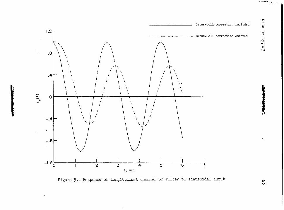
I n o r d e r t o i l l u s t r a t e t h e e f f e c t of the ro l l i ng co r rec t ions i n t he c ross - ro l l f i l t e r , equa t ions (2) and (4) were used to ca l cu la t e t he response of a simple f i l t e r and of a f i l t e r i n which the c ross - ro l l correct ion was used. It was assumed that an error f ixed in space was viewed from a s teadi ly ro l l ing in te rceptor ; thus ,
"f 3 3 "f
E(%) = i ( 0 ) + j E a ( t ) - U,(t)
where the e leva t ion and azimuth components of the error are given by E e ( t ) = Eeo cos p t and Eao( t ) = -Eeo s i n p t because of t he ro l l i ng veloci ty of the interceptor . In addi t ion, it w a s assumed t h a t the f i l t e r w a s i n i t i a l l y charged, which gave Eeo(0) = Eeo(0) and Eao(0) = Eao(()) = 0. When these inputs and in i t i a l cond i t ions are used, the solut ion for e leva- t ion channel of the simple f i l t e r i s
where 0 = tan-'(,p). This equation clearly shows the dependence of E e ( t ) on the in te rceptor ro l l ing ve loc i ty and f i l t e r time constant. When the cross-rol l correct ion i s included i n equation (k), the so lu t ion for E e ( t ) i s
E e ( t ) = E, COS p t ( 6 ) 0
which i s the unmodified input of t he f i l t e r . Th i s so lu t ion i s obtained under the assumption of an i n i t i a l l y charged f i l t e r where the t r ans i en t so lu t ion goes t o zero and leaves only the steady-state solution.

NACA RM L57G23 - 9
For purposes of comparing these solutions, equations ( 5 ) and (6) have been plot ted in f igure 3 f o r a uni t E, and a value of p of 2.5 radians
attenuated and lags the input by the angle 8; whereas, when the cross- r o l l correct ion is included, the output of the f i l t e r system i s the same as the input. The attenuation and phase l a g of the output of the simple f i l t e r a r e caused by the smoothing of t he changes i n E, tha t ase due t o motion of the interceptor . The cross-roll correct ion appl ied in the cross- r o l l f i l t e r compensates f o r t h e changes i n E, due t o i n t e r c e p t o r motion and thus eliminates the attenuation and phase lag.
I per second. These r e s u l t s show that the output of t he s imp le f i l t e r i s
j
Figure 4 presents the e f fec t of omit t ing the cross-rol l correct ion i n t h e f i l t e r on the response of the interceptor . The main e f f ec t of the cross-rol l correct ion i s t o smooth the o sc i l l a t ions t ha t occu r i n the airplane response. This smoothing may be of importance i n t h e r o l l response as it i s the roll response that determines the magnitude of t he sidewise acceleration impact on t h e p i l o t ' s head during the maneuver. The data obtained in th i s s tudy d id no t ind ica te a s ignif icant dif ference in the predicted terminal miss dis tances when the c ross - ro l l cor rec t ion w a s omitted.
The Command Computer
The function of the command computer i s t o convert the f i l tered s teer ing e r rors (E, and ee) to automatic-pilot commands. As €e represents a f l igh t -pa th e r ror , no further modification of th i s quant i ty wa.s necessary, and the value of the e r ror was passed on t o the g- l imiter and automatic p i lo t . In the case of t h e r o l l command, i t was des i r ed t o command a roll ra te tha t var ied d i rec t ly wi th the magnitude of the bank- angle error. The desired change i n bank angle $, was defined by the equation
pl, = t a n - -1 E a
€e
which neglects the effect of gravi ty on the magnitude of t he bank angle. One r e s u l t of omitting gravity considerations i s the introduction of large r o l l o r d e r s f o r a f i n i t e as €e +O. When the low-gain fl ight-path- control system of reference 1 was used to con t ro l t he l ong i tud ina l motion of the a i rp lane , sa t i s fac tory roll control was obtained (see f ig. 5 ) . A s shown i n f i g u r e 5 ) however, subs t i tu t ion of the high-gain flight-path- cor$rol system caused unsatisfqctory r o l l response. The time h is tory of
> '"'e for the high-gain flight-path-control systems changes sign several t, + T
€5 t imes while that for the low-gain flight-path-control system does not change sign. As E e i s the smoothed value of %, which by def in i t ion
I- -
10 a- NACA RM L57G23
M, tg + r M,
i s , changes i n t h e s i g n of generally produce cor- 'm tg + 7
'3' + tg + T responding changes i n s i g n i n ee. These sign changes i n m e t h e cause of the v io len t ro l l ing motions shown i n f i g u r e 5.
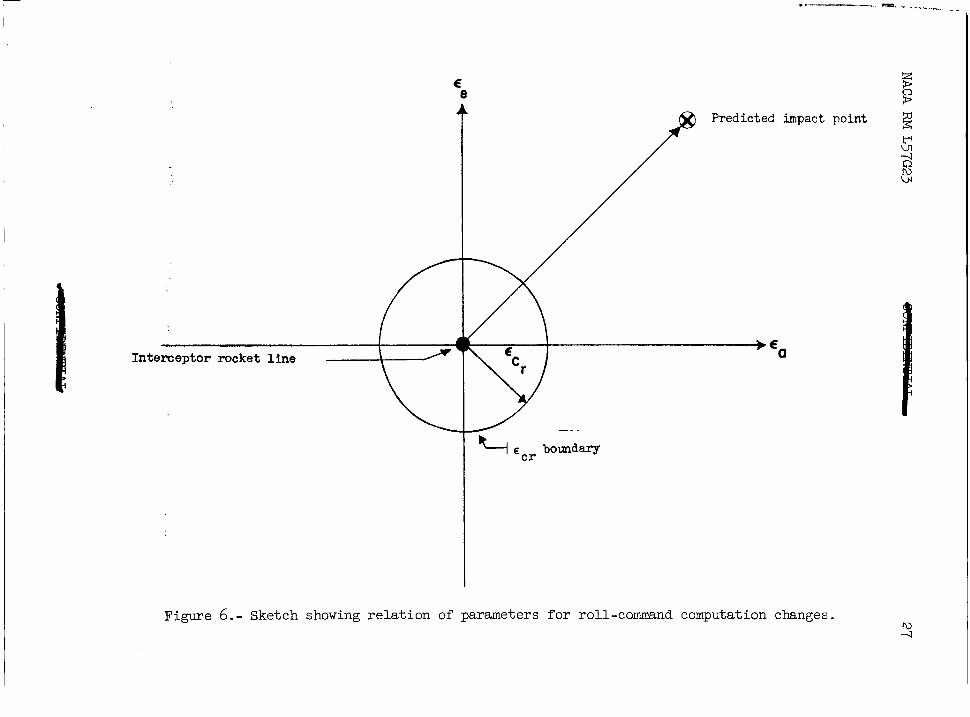
Three modifications of the mc tangent roll-command computation were studied to determine if the l a rge ro l l ing motions could be eliminated. Figure 6, which presents a sketch of the command-computer output, i s used in the d i scuss ion of these modifications. The axes of the computer a r e ' coincident with the reference axes of the interceptor , and the predicted impact point may appear i n any one of the four quadrants. The predicted impact point i s displaced from the or igin by the s teer ing e r rors
(along the Y axis) and Ee (posftive along the negative Z axis of the Interceptor) . The circle centered at the origfn wlth a radius of cCr i s cal led the E C r boundary. The value of cCr i s a predetermined value of E which is t h e t o t a l s t e e r i n g e r r o r and i s defined as
E = + €e2. As the interceptor maneuvers t o reduce t h e s teer ing e r r o r s t o zero, the predicted impact point and the o r ig in , which repre- sents the rocket l ine of the interceptor move towards each other. When
-~
E = /" 5 Ecr, the predicted impact point appears within the E C r boundary. .
The f i r s t modi f ica t ion of the roll command used the dead-zone con- cept, and no-rol l control was provided within the cCr boundary. The value of cCr was based on the maximum acceptable miss distance for a k i l l which gave an cCr of about 0.01667. T h i s method proved completely unsatisfactory because the interceptor did not f l y so as to hold the s teer ing error within the E C r boundary. Very e r r a t i c motions occurred whenever the cCr boundary was crossed. In the second modification of
the roll command, the computation was changed from 31, = t a n - t o €e gC = K E a inside the E C r boundary. This modification gives control
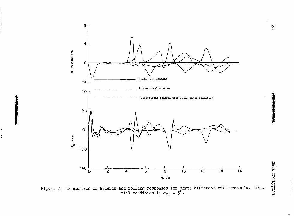
proport ional to the azimuth steering error. Several runs were made t o determine a reasonable value of K and the s ize of the proportional control zone. It was found that values of K = 16 and eCr = 0.03 pro- vided good but not optimum control. As shown i n f i g u r e 7, t h i s modified r o l l command considerably decreased the very large rolling velocities t h a t occur when €e passes through zero; however, the interceptor did n o t f l y s o as to hold the s teer ing error within the proport ional control zone, and re la t ive ly l a rge ro l l ing ve loc i t ies s t i l l developed when the
boundary was crossed. The frequency of the crossings was much l e s s
-1 ea

11
than i n t h e f i rs t modification. The t h i r d and f inal modif icat ion of t he
t h a t i s , the select ion of the smallest of the two possible bank angles
the s teer ing error dot appears in the fourth quadrant of f igure 6, t he interceptor can roll t o t h e r i g h t through a bank angle greater than 90' o r r o l l l e f t through a small bank angle and use negative normal accelera- t i o n t o c l o s e on the t a rge t . The third modification i s the same as the second except t h a t when i s negative the bank-angle command p(c i s multiplied by -1. It should be noted tha t th i s modi f ica t ion ( the m u l t i - p l ica t ion by -1) occurs only within the cCr boundary. As the r o l l con- t r o l i s proport ional to the azimuth s t ee r ing e r ro r i n t h i s r eg ion , t he negative of t h e t r u e azimuth s teer ing e r ror w i l l cause the airplane to r o l l through the smallest bank angle and push d m on the target . This third modification of t h e r o l l command caused t h e i n t e r c e p t o r t o f l y s o t h a t t h e s t e e r i n g e r r o r was held within the proportional control zone. A s shown i n f i g u r e 7, the amplitude of t h e r o l l i n g motions i n t h e last p a r t of the attack run has been considerably reduced, when compared t o those obtained with the other r o l l commands, and a smoother r i d e f o r t h e p i l o t i s obtained. It i s in t e re s t ing t o no te t ha t w i th t h i s last roll- command modification, the smallest predicted terminal miss distances were obtained. It should be noted that this decrease in the miss distance was not significant in determining the success or failure of the attack run.
d. roll-command computer introduced the concept of small bank-angle selection,
I s t h a t e x i s t f o r a given s i tuat ion, in the proport ional control zone. If
The use of t he small bank angle introduced a new problem. Whenever the in te rceptor ro l led to the smal les t bank angle, i t r o l l e d and side- sl ipped in such a manner t h a t it assumed an inverted posi t ion below t h e t a r g e t and completed the run by pulling up with negative normal accelera- tion. This condition, which may have been caused by the omission of gravity considerations i n t h e roll-cormnand computation, i s i l l u s t r a t e d by the t ime his tor ies of normal acceleration and the direct ion cosine shown i n figure 8. n3
The g-limiter
A g-limiter was used i n t h i s study t o r e s t r i c t t h e normal accelera- t i o n of the in te rceptor to rea l i s t ic va lues . No attempt w a s m a d e t o study the overal l g- l imit ing problem; however, during the course of this inves- t i g a t i o n some rather interest ing information w a s obtained on g-limiting.
Some preliminary simulator f l ights were made with a feedback type of g-limiter. With th i s type of l imi te r , the normal accelerat ion of t he
case 5g or -2g, a signal was f e d d i r e c t l y t o t h e e l e v a t o r s e r v o t o reduce the normal acceleration. Because t h e normal accelerat ion had t o develop before the limiter could r e s t r i c t it, large overshooting developed due t o t h e time l a g between the action of the e levator and the change i n normal acceleration.
, @ a airplane was measured and when it exceeded a predetermined value, i n t h i s
12 wmmmwmb NACA RM L57G23
As shown i n f i g u r e 1, the command g-limiter operates on the incoming command so that the comnded s teady-state normal acceleration never exceeds the desired value. As the charac te r i s t ics of the a i rplane and automatic pilot influence the sett ing of the g-l imiter, a l inear analysis was made for longi tudinal control systems w i t h and without inner-loop integrators to determine the important parameters for the g-limiter se t t ing . The transfer function for ?/€e of this control system (see f i g . 1) i s
where F(s) and H(s) are the airplane transfer functions q/6, and ?/tie, respectively, based on a representation of the motion of the a i r - plane by the pitching-moment and normal-force equations. The two cases t h a t were considered corresponded t o an inner-loop integrator included (Q # 0) and the inner-loop integrator deleted from the control system (Kg = 0). The steady-state ?/€e for a step input of €e is obtained from equation (8) by l e t t i n g s approach zero. Thus, f o r K 8 # 0
and f o r K 8 = 0
where C i s a constant, and
The above steady-state expressions were used t o determine g-limiter se t t ings . When the integrator was included, (Q # 5 ) , the g-l imiter s e t t i n g i s given by

NACA RM L57G23
and when the integrator w a s deleted ( K 8 = 0) , by
13
I Equations (12) and (13) show tha t the a i rp lane and autopilot chasacter-
integrator i s included i n t h e c o n t r o l system but tha t the a i rp lane automatic-pilot characterist ics must be accounted fo r i n t he g - l imi t e r s e t t i n g when the inner-loop integrator i s omitted from the longitudinal- control system.
i i s t i c s do not influence the sett ing of the g- l imiter when the inner-loop 3
I,
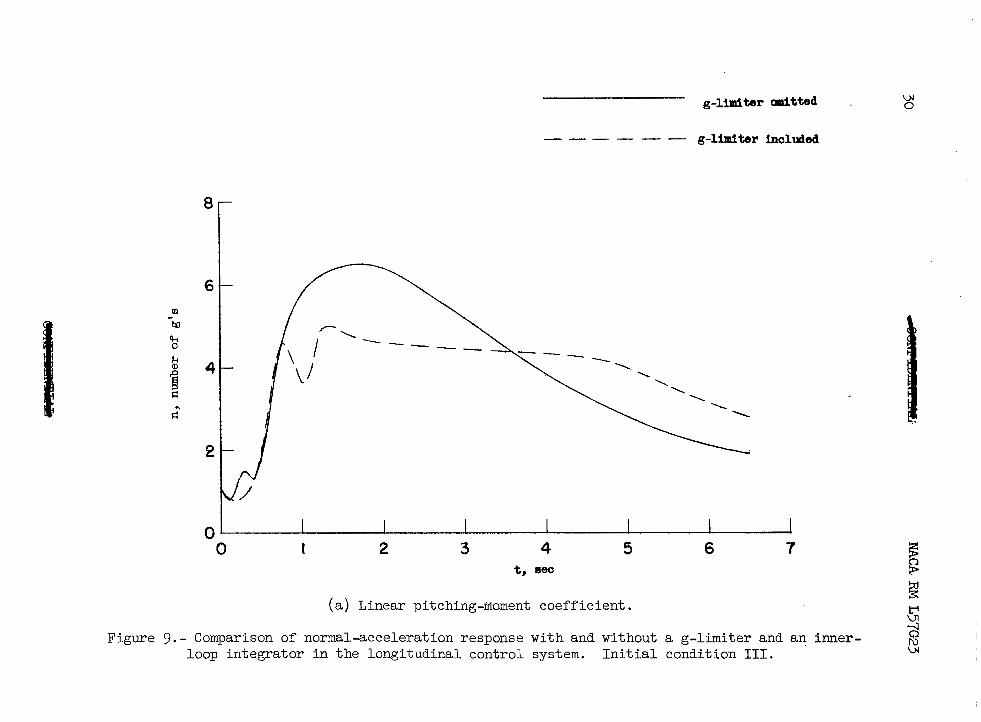
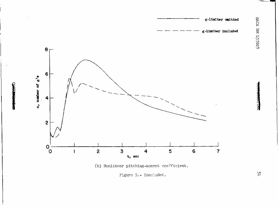
Figure 9 shows the norinal acceleration response of the control system with the inner-loop integrator included in the control system. Figure 9(a) shows the ' limited and unlimited normal-acceleration responses for init ial condition 111 with a l inear pi tching moment. A s can be seen, the unlimited case i s completely unsatisfactory; whereas, the limited case remains below t h e 5g limit. Figure 9(b) shows the same responses when the pitching moment i s nonlinear. Again the unlimited response i s much too h igh to be sat isfactory. With the g-l imiter in operation, the normal acceleration has a maximum overshoot of about 0.5g, but the average normal acceleration i s about 5g. Figure 10 shows the case where the inner-loop integrator i s omitted from the control system. When the pitching moment was l inear the m a x i m u m overshoot was about 1.4g, and, when the pi tching moment was nonlin- ear, the m a x i m u m overshoot was about 2.8g. No runs for unlimited accelera- t ion are usable for these cases as a severe limiting condition rendered the resul ts quest ionable . The extreme overshoots i n t h e c a s e of the non- l inear p i tch ing moment were probably caused by t h e f a c t t h a t C% was assumed t o be constant i n determining the g-l imiter sett ing but Cm was varied as a function of angle of a t tack and Mach number in the pi tching- moment equation. The g-limiter response, when the inner-loop integrator i s omitted, i s considered unsatisfactory, even though the average normal acceleration i s about 5g with a l inear pi tching moment, because of the magnitudes of t h e i n i t i a l overshoots which could severely overload an airplane.
It should be noted that the automatic-pilot gains were d i f f e ren t fo r t he two cases considered; however, th i s d i f fe rence in ga in does not affect t he results as far as the in tegra tor i s concerned because the same value of the gains was used in the automatic-pi lot se t t ing and in t he g - l imi t e r s e t t i ng .
The Maneuvering Target
In order to understand the problems involved i n developing a control system f o r an interceptor t racking a maneuvering t a rge t , it i s necessary

t o understand how the orders suppl ied to the control system are obtained. The vector equation
presents a f i rs t -order s imulat ion of the miss-distance prediction for +cad-collision f i r e c o n t r o l . When the t a rge t ve loc i ty remains unchanged (G i s zero), this equation provides an accurate solution of t he f i r e - control problem. If the target develops an acceleration, this equation no longer gives an accurate solution as there are no acceleration terms included in the p red ic t ion ; however, there i s an e f f ec t on the prediction due t o t h e h i s t o r y of ta rge t motion. A s the target veloci ty vector VT changes under the influence of the target accelerat ion, d i f ferent miss- distances are predicted which cause the interceptor to change from st'eady to accelerated flight. Equation (14) shows, and analog studies substan- t i a t e , t ha t t he i n t e rcep to r develops an acceleration approximately pro- po r t iona l t o t ha t of the target ; however, i n order t o develop and hold this accelerat ion, for the formulat ion of the f i re -cont ro l problem pre- sented in equation (14), a steady-state error must ex is t . In addi t ion to t h i s s t eady- s t a t e e r ro r , an additional error i s introduced which a r i s e s because the target i s accelerating while the rocket i s t ravel ing from the f i r i ng po in t t o t he impact point predicted a t t h e i n s t a n t of f i r i n g (tg = 0) .
It i s most natural to consider the addi t ion of acceleration terms t o f i r s t -order computer as a so lu t ion t o t h i s problem. Unfortunately, accel- eration terms are hard to ob ta in from the airborne intercept radar, and to da t e l i t t l e success has been at ta ined w i t h second-order computers, primarily because of the noise associated with acceleration information.
There a re two other methods available for reducing the steady-state tracking error. One method i s t o introduce a t racking integrator which adds an in t eg ra l of the s teer ing er ror to the input of the g-l imiter.
' The second method i s to increase the forward-loop gain, n/ce, of the longitudinal control system. Simply s t a t e d , t h i s l a t t e r method means tha t t he amount of normal acceleration ordered per degree of s teer ing e r ror i s increased. Neither of these methods affects the error introduced by target acceleration during the time of f l i g h t of the rocket. Unless second-order computing is used, t h i s i s an e r ro r t ha t must be tolerated; however, it can be kept small by using short times of rocket flight. Both of these methods are discussed in reference 6 for the vertical-plane problem. As shown in re fe rence 6, the tracking integrator reduces the steady-state tracking error to zero when optimumized f o r a specific case; however, the resu l t s of reference 6 appear to indicate that the t racking- integrator gain should be a nonlinear function of s teer ing e r ror or miss

NACA RM L57G23 - 15
distance for the t racking integrator to funct ion equal ly wel l for a l l conditions. The problem of a nonlinear gain i s thus introduced. The second method, which increases the n/ce of the airplane-autopilot com- bination, does not eliminate the steady-state tracking error but reduces th i s e r ro r t o accep tab le magnitudes. This condition occurs because some e r ro r i s needed i n order t o cause the interceptor to maintain normal acceleration to track the target. Generally speaking, control-system s tab i l i ty cons idera t ions w i l l d i c t a t e t h e m a x i m u m forward-loop gain that can be used which, i n t u r n , w i l l determine the tracking error.
I n order t o avoid the complexity of a nonlinear gain, a high-gain longitudinal control system w a s used i n t r a c k i n g runs against the maneu- ver ing target . The forward-loop gain of t h i s con t ro l system was adjusted s o t h a t a value of n/Ee of 1.4 was obtained for the airplane-autopilot combination.
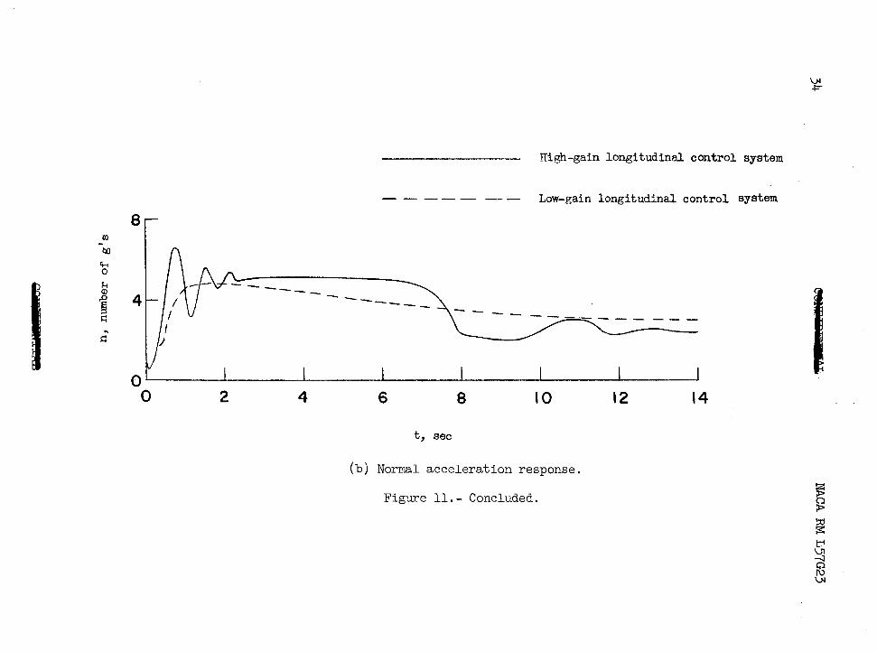
In o rder to ob ta in some idea of t he e r ro r s t ha t occw when a con- t r o l system found satisfactory against nonmaneuvering t a rge t s i s used t o t r a c k a maneuvering target, tracking runs were made against a maneu- vering target with the two longitudinal control systems used i n t h i s study. Time h i s to r i e s of the interceptor t racking a nonmaneuvering tar- get using these longitudinal control systems, a low-gain one and a high- gain one, are presented in reference 1.
Figure 11 compares the t r ack ing ab i l i t y fo r t he low-gain and high- gain longitudinal control systems when the t a rge t was making a 2g pull-up. The low-gain control which has a value of n/ee of 0.4 gives a miss distance of approximately 403 f e e t , and the high-gain control system which has a value of n/ce of 1.4 gives a miss distance of about 115 feet which, for purposes of t h i s study, was considered t o b e an acceptable m i s s distance.
The use of a high-gain control system and a comand g-limiter pre- sent an interest ing problem i n system requirements. The use of an inner- loop integrator with the command type of g-limiter i s most desirable as it i s an important factor in obtaining an accurate normal acceleration res t r ic t ion ; however, when the forward-loop gain i s increased t o o b t a i n good tracking of a maneuvering target, the presence of the in tegra tor introduces an oscillation which has a period of approximately 30 seconds and damps t o one-half amplitude i n about 34 seconds. The removal of t h e integrator e l iminates this osci l la t ion. The problem presented i s t h a t of obtaining a compromise which provides enough in tegra t ion to g ive acceptable g-limiting and a t the same time introduces no unacceptable osc i l l a t ions when a high forward-loop gain i s used. As would be expected, t h e combination of high gain and the continuous d e m d for normal accel- e ra t ion resu l t ing from the maneuv$r of t h e t a r g e t produced a most undesir- able rate l imi t ing condi t ion in 6,. The use of the nonlinear pitching moment in the a i rplane representat ion aggravated the rate limiting condi-

16 NACA RM L57G23
t i o n and increased the roughness of the r ide. A pitching-acceleration feedback loop w a s added to t he con t ro l system i n an attempt t o a l l e v i a t e the rate l imiting condition. Figure I2 shows t he e f f ec t of a pitching- acceleration feedback w i t h a gain of 0.1when a nonlinear pitching moment was used. The inclusion of this feedback completely eliminates the rate- l imit ing osci l la t ion in the control-surface motion. The control of this osc i l l a t ion smooths the response of the airplane. Figure 12 a lso ind ica tes tha t the ra te - l imi t ing osc i l la t ion does not a f fec t the ab i l i ty of the interceptor system t o reduce the elevation steering errors.
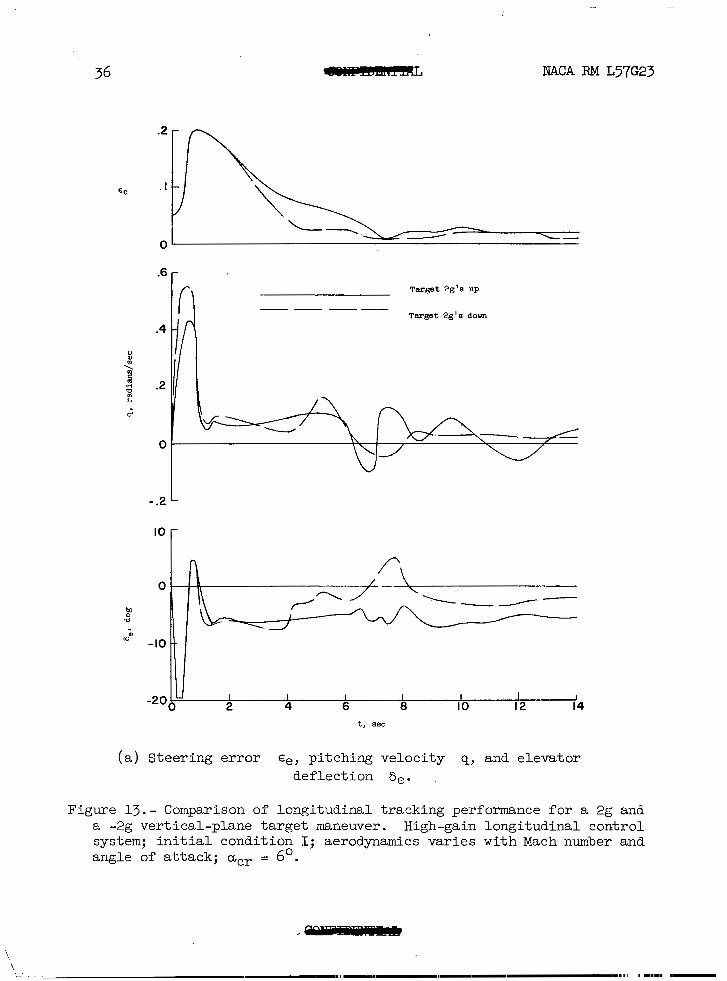
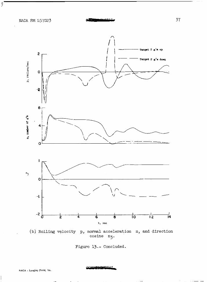
The study also included the case of a t a rge t performing a 2g push- down maneuver. As the interceptor normally starts below the t a rge t , the interceptor starts t o p u l l up towards the predicted interception point. In the case of target pull-up, the interceptor keeps pulling up; however, when the target executes a push-down maneuver, the downward motion of the ta rge t and the upward motion of the interceptor cause the predicted impact point to appear below the f l i gh t pa th of the interceptor . %e interceptor m u s t , therefore, reverse i t s d i rec t ion e i ther by r o l l i n g t o p u l l down on the predicted impact point or by ro l l i ng through a small angle and pushing down. It was ant ic ipated tha t t h i s change i n d i r e c t i o n might cause deteri- oration of the interceptor t racking performance. Figure 1.3 compares the tracking of the in te rceptor for a 2g pull-up and a 2g push-down by the ta rge t t h a t s t a r t ed a t r ada r l ock on. In the 2g push-down maneuver the interceptor rolls onto i t s back and pulls d a m on the target . Also f ig - ure 13 shows that this la rge ro l l ing maneuver causes l i t t l e or no d i f f e r - ence in the t rack ing performance of the interceptor.
SUMMARY OF RESULTS
With the use of an automatic interceptor system i n which gravity considerations were omitted i n t h e roll-command computation, the func- t ioning of t h e e r r o r f i l t e r system with cross roll, the command computer, and the g-limiter have been studied. The two target conditions studied were a s t ra ight - f ly ing ta rge t and a t a rge t t ha t made a f2g vertical-plane maneuver. The r e su l t s of the investigation showed the following:
1. The inclusion of the cross-roll correction when f 5 l t e r i n g i n a rotating axes system i s desirable. This correct ion tends to reduce rol l ing accelerations and the amplitude of the ro l l ing ve loc i t ies which determine, t o a large degree, the side forces acting on t h e p i l o t ' s head and the roughness of the motion experienced by the p i lo t .
2. The method used t o compute the f l ight-path command proved s a t i s - factory. However, the roll"command computation deteriorated as the smoothed elevat ion s teer ing error approached zero. The two methods t r i e d for the correction of this d i f f i c u l t y were only partially successful; how-

NACA RM L57G23 I I
17
! ever, the trends shown in these resul ts appear to indicate that a s a t i s - factory method of determining roll commands when gravity considerations are omitted from the command computation can be developed.
; 3. For the conditions of this study, the command type of g-limiter proved more satisfactory than the feedback type of g-limiter. The r e su l t s obtained indicate that the operation of the command type of g-limiter i s be t t e r when the longitudinal control system contains an inner-loop inte- grator than when the integrator i s omitted.
4. The high-gain longitudinal control system provided acceptable tracking against targets performing +2g vertical-plane maneuvers; how- ever , the total error was beginning t o approach unacceptable magnitudes.
3. The high-gain longitudinal control system and the g-limiter pre- sent conflicting requirements. The response of the former i s b e t t e r without the inner-loop integrator while the latter requires the inner- loop integrator in order to obtain an accurate normal acceleration res t r ic t ion .
Langley Aeronautical Laboratory, National Advisory Connnittee for Aeronautics,
Langley Field, Va., July 16, 1957.
"

18 NACA RM L57G23
1. Sherman, Windsor L., and Schy, Albert A. : Theoretical Investigation of the Attack Phase of an Automatic Interceptor System at Supersonic Speeds With Particular Attention to Aerodynamic and Dynamic Repre- sentation of the Interceptor. NACA RM ~56~08, 1957.
2. Schy, Albert A., and Gates, Ordway B., Jr.: Analys.is of Effects of Airplane Characteristics and Autopilot Parameters on a Roll-Command System With Aileron Rate and Deflection Limiting. NACA RM L55E18, 1955.
3. Woodling, C. H., and Gates, Ordway B., Jr.: Theoretical Analysis of the Longitudinal Behavior of an Automatically Controlled Supersonic Interceptor During the Attack Phase Against Maneuvering and Non- maneuvering Targets. NACA RM ~55~18, 1955.
4. Margolis, Kenneth, and Bobbitt, Percy J.: Theoretical Calculations of the Stability Derivatives at Supersonic Speeds for a High-speed Airplane Configuration. NACA RM L53G17, 1953.
5. Anon. : Integrated Fire Control - Flight Control System IIN. Interim Engineering Rep. EM-185-7 (Contract No. NOas-52-222-C), North American Aviation, Inc., July 1, 1952, pp. 23-41.
6. Schy, Albert A., Gates, Ordway B., Jr., Woodling, C. H., Sherman, Windsor L., and Sternfield, Leonard: Simulator Studies of the Attack Phase of an Automatically Controlled Interceptor. I - Preliminary Studies of the Lateral and Longitudinal Control Systems, by Schy, Gates, and Woodling. I1 - Some Results of a Study Performed on the Typhoon Computer, by Sherman and Sternfield. NACA RM L55E27a, 1955

I " - 19 NACA RM L57G23
TABLE I
INITIAL CONDITIONS FOR THE ATTACK PROBLEM
All angles in rad ians , a l l d is tances in feet, a l l v e l o c i t i e s i n fee t per second or radians per second
Angle rotation order: Euler angles qJ 8, reference space Gimbal angles ea, 8, reference body 1 L J
I1 V I In i t i a l cond i t ion I V
0
0.0332
0
2136
2135
0
70 52
60,000
-0.7854
0.2618
111
0
0.0332
0
2136
2135
0
70 52
60,000
-0 7854
0
I
li "
2
0.0332
0
2136
2135
0
70.52
60,000
-0.08275
0
li 2
0
I 8 0 0.0332 0.0332
0 0
2136 I 2136
2135 2135 UO
0 0 vO
70.52
6oJ 000
wO
I RO
l e &O -0.2618
0.2618
All z e r o i n i t i a l l y
I vT
1359 fo r all i n i t i a l cond i t ions VI = i( 0 ) + j (1359) + h( 0) i n space
50,000 f o r a l l i n i t i a l cond i t ions
971 f o r a l l i n i t i a l cond i t ions
. .
I HT
Speed of sound
Iu 0
Figure 1.- Block diagram of interceptor f l ight-control system.

w
(a) Geometry of a t tack problem.
Figure 2.- In i t ia l condi t ions .
22
(b) Pictorial presentation of initial conditions.
Figure 2. - Concluded.
I .2
.a
.4
- 0 +" W
-.4
-.E
-1.2
Cross-roll correction included
-""" Cross-rol l correct ion omit ted
I 2 3 4 5 6 7 t, 8ec
Figure 3 . - Response of longitudinal channel of f i l t e r t o s inuso ida l i npu t .

24 NACA RM L27G23
"---
Cross-roll correction mltted
4
-4
""" Cross-roll correction included
L
' r
n &
I I I I I I I 0 2 4 6 0 IO 12 14
t, 8ec
(a) Angular ve loc i t i e s .
Figure 4 . - Comparison of airplane response with and without cross-roll cor rec t ion inc luded in f i l t e r . In i t ia l condi t ion I.

3
-30 OL Cross-roll correction omitted
”” Cross-roll correction included
3
-400-
-800 I I I I 1 2
I 4 6 8 IO 12 14
t, sec
I
(b) Linear veloci t ies .
Figure 4.- Concluded.

26 NACA RM L37G23
4 1 A
Figure 5.- Comparison of behavior of miss distance parameters (&/t + 7 )
and (M3/tg + T) and roll response of the airplane for low-gain and high-gain longitudinal control systems. Initial condition I.
g
€ e
f I
Interceptor rocket l ine
Figure 6.- Sketch showing relation of parameters for roll-command computation changes.
*r
!a
-4 L" Basic roll ccnnnand
40
20
0
Y 2 a ..
-20
- - - - - Proportional control
- 40 I I I I I I I I 0 2 4 6 0 I O 12 14 16
t, 8EC
- - - - Proportional control with small angle s e l e c t i o n
t, 8EC
Figure 7.- Comparison of a i le ron and roll ing responses for three different r o l l commands. t i a l condition I; acr = 3 . 0

-4 L
“3
I I I I I 0 2 4 6 8 IO 12 14
t, BBC
Figure 8.- Time histories of normal acceleration n and direction cosine n3 obtained for a proportional roll command with small bank selection. Initial condition I.
v3 N
g-limiter araitted
g-limiter included “””
w 0
0 I 2 3 4 5 6 7 E t, 8eC
h P
(a) Linear pitching-Moment coefficient . Figure 9.- Comparison of normal-acceleration response with and without a g-limiter and an inner-
I? UI “1 8
loop integrator in the longitudinal control system. Initial condition 111. w
g-linaiter m l t t e d
""" g -limiter included
I I 2 3 4 5 6 7
t, 8BC
(b) Nonlinear pitching-moment coefficient.
Figure 9. - Concluded. w P

8 -
6-
4-
2-
Linear C,
- - - - - - - Nonlinear Cm
w Iu
t, sec
Figure 10.- Normal acceleration response of airplane with a command g-limiter and no inner-loop integrator in the longi tudinal control system f o r l i nea r and nonlinear pitching moments. Ini t ia l condi t ion 111.

i
i NACA RM L57G23 33
.2
E .I
0 ""
Low-gain longitudinal control system
M a a
e LD
"
"
I I I I I I
0 2 4 6 8 IO 12 14 I I I I I I
0 2 4 6 8 IO 12 14 t, sec
(a) Steer ing e r ror €e, pi tching veloci ty q, and elevator def lect ion 6,.
Figure 11. - Comparison of longitudinal tracking abi l i ty of low-gain and high-gain longitudinal control systems t a r g e t 2g vertical-plane maneu- ver. Attack run defined by in i t i a l cond i t ion I.
w ?=
High-gain longitudinal control system
""-" Low-gain longitudinal control system
t, sec
(b) Normal acceleration response.
Figure 11. - Concluded.
. .

I
NACA RM L57G23 - 35
.2 -
," .I
J
-
0
.8
.4
U
- .4
- .8
20
Pi tch ing-acce lera t ion feedtack ga in = 0
"" Pitching-accelerat ion feedback r a i n = 0.1
E I
i a $ 0
I
.. m lo
- 20 '. 0 2 4 6 8 10 12 14
t, 8eC
Figure 12.- Effect of pitching-acceleration feedback on longitudinal tracking performance. Target 2g vertical-plane maneuver. Interceptor initial condition I; nonlinear aerodynamics; a,, = 6 O .
36 NACA RM L57G23
.2
Be . I
0
IO
0
W \-/ -
'c)
m In -10 "
-200- 2 I 4 I 6 I I I I I 8 IO 12 14 t, aec
(a) Steering error €e, pitching velocity g, and elevator deflection 6e. ,
Figure 1 3 . - Comparison of longitudinal tracking performance for a 2g and a -2g vertical-plane target maneuver. High-gain longitudinal control system; initial condition I; aerodynamics varies with Mach number and angle of attack; acr = 6'.
NACA RM L57G23
/ I I I" Targe t 2 g's d m
T a r g e t 2 g'e up -
37
2
n.
-2
0
-1 I y r
I
"3
0
- I
-2 I I I 2 4 6
I I I a
I IO 12 14
t, sec
(b) Rolling velocity p, normal acceleration n, and direction cosine n3.
Figure 13. - Concluded.
NACA - Langley Field, Va.
