research field: structural glass departmentof steel and ... · experimental research at the...
TRANSCRIPT

M. SLIVANSKÝ
EXPERIMENTAL VERIFICATION OF THE RESISTANCE OF GLASS BEAMS
KEY WORDS
• structural glass,• laminated glass,• beams• reinforcement,• post – breakage structural capacity.
ABSTRACT
Experimental research at the Department of Steel and Timber Structures at SUT in Bratislava focused on the verification of the behavior of modern glass structures. Four types of glass beams were tested - laminated beams made of annealed (ANG) and fully tempered glass (FTG) in interactions with or without steel elements (as reinforcement). The results of the experimental research were also compared with theoretical models using FEM calculations.
Miloš SLIVANSKÝemail:[email protected]:structuralglass
Address:DepartmentofSteelandTimberStructures,FacultyofCivilEngineering,SlovakUniversityofTechnology,Radlinského11,81368Bratislava
Vol. XX, 2012, No. 1, 21 – 28
1. INTRODuCTION
The nature of unpredictable and brittle failures is the crucialdisadvantageoftheuseofglassasastructuralmaterial.Improvingthe resistance of glass elements has often been realized bymulti-layeringglasssheetswithPVBfoilinthepast,anditwasessentialto overdimension the glass structure. The load-bearing capacityof the partly damaged laminated glass element at a reduced levelof stress was considered. Fully tempered glass was usually used,becauseasaresultofheattreatment,itdemostratesahighertensilestrength[8],[2].Theconceptof reinforcedglassbeams focusesonways toensurethe plastic (ductile) failure behaviour of the element.This ductilefailure behaviour is obtained by bonding a reinforcement profilein the tensile zone along the edge of the glass beam. Exceedingthe tensile strength of glass causes the initial formation of tensilecracks,butthegrowthofthecracksislimited.Thefracture‘senergy
ispartlyusedfordeformationofthereinforcement,whichtransfersthe tensile forces at the point of the crack. Together with thecompressionforcesintheuncrackedglass,aninternalcouplingoftheforces iscreated,and thereinforcedbeamisstillable tocarrytheload.Therehavebeenseveralresearchprojectsrealizedabroaddedicatedtoreinforcedorcompositeglassbeams.Exceptforsteelreinforcement
Fig. 1.1 Schematic overview of the distribution of the force after the failure of glass [8].
2012 SLOVAK uNIVERSITY OF TECHNOLOGY 21

22 EXPERIMENTAL VERIFICATION OF THE RESISTANCE OF GLASS BEAMS
2012/1 PAGES 21 — 28
profiles,acombinationofglasswithothermaterialshasalsobeenused.AbriefoverviewofthemostrecentworksisgiveninFig.1.2.Theseworksexaminedglassbeamsreinforcedwithsteelstrapsorprofiles [8], [9], carbon-fiber reinforced glass beams [10], glass-concrete composite beams [4], glass-timber composite beams [7],[6],andalsoglassbeamswithsteelflanges[11],[3],[5].
2. TYPES OF BEAMS, MATERIAL AND GEOMETRY
The first part of the experimental research focused on the basicmechanical properties of glass as astructuralmaterial. The effectoftheheattreatmentofglass(tempering)onitsstrengthintensionandtheimprovementof thebendingresistanceof theglassbeamswereexamined.In the second part of the experimental research the behavior ofglassbeams reinforcedwith stainless steelprofiles (as strips)wasexamined. Reinforcing profiles were attached to the bottom edgeon both surfaces of the glass by means of an epoxid glue. Theexperimental resultswere evaluated in terms of the nature of thecollapse at different stress levels and the different states of theoperationofthereinforcedglassbeam.
The glass beam specimens had dimensions of 1500 x 130 mm,and laminated glass (annealed or fully tempered) was used fortheirproductionwithasheetthicknessof5mmandPVBfoilwithathicknessof0.76mm.Thetheoreticalthicknessofthelaminatedglasspanewastherefore10.76mm.AstainlesssteelprofileoftheEN1.4301material‘squality,respectivelySTN17240,wasusedasareinforcingprofile.Aprofileof15x3mmwasattachedtobothsurfaces of the glass pane along the tension edge. Details of thereinforcedglassbeamwithastainlesssteelprofileareshowninFig.2.1.The two-component LoctiteHysol 9466 epoxy adhesivewasusedforbondingthereinforcingprofile.
2.1 Preparation of the experiment
All the types of glass beamswere tested using a4-point bendingtest.Thetheoreticaldistancebetweenthesupports(span)was1400mmwith1500mmasthetotallengthofthebeams.Thespecimenswere loadedsymmetricallyat twopointsatadistanceof200mmfrom the middle of their spans. The total distance between thesupportsoftheloadinggirderwastherefore400mm.Theloadinggirder and the test samples were fitted together in aZDMU 30stationaryhydraulictestingmachinewithamaximumloadingforceof100kN(Fig.2.2).ThecourseoftheloadingtestwasrecordedusingaHBMSpider8measuringstation,andthedatawerestoredinaPC(notebook)viatheCatman utility software.Themeasured datawere exported toaMicrosoftExcelfileformataftertheloadingtesthadfinished.Thefollowingdataweremeasured:• verticaldeformationoftheglassspecimen 5x• horizontaldeformationoftheglassspecimen 1x• trajectoryofthetestingmachinejack 1x• loadingforce 1x• strainmeasurementoftheglassspecimen 4x
3. EVALuATION OF THE MEASuREMENTS
Sixteen glass beam samples were tested in the laboratory of theDepartment of Steel andTimber Structures at SUT in Bratislava.Thespecimensweresortedaccordingtothetypeofglass(ANGfloatglassorFTGfullytemperedglass)andthebeamtype(unreinforcedorreinforced=Reinforced)into4basicgroups.
3.1 Testing of the unreinforced beams
Thebrittlebreakingbehaviorof theglasselements forboth typesof beams (ANG and FTG) occurred through their total collapse,whichhadnotbeenprecededbyanynoticeableformationofcracks,
Fig. 1.2 Similar structural glass composite beam concepts [8].
Fig. 2.1 Glued reinforcing profile (detail), scheme and actual performance.

2012/1 PAGES 21 — 28
23EXPERIMENTAL VERIFICATION OF THE RESISTANCE OF GLASS BEAMS
so the beams suddenly failed. For the beamsmade of float glassthe final damagewas strictly of alocal character (one crack andintact compact parts); the beams made of fully tempered glasswerebrokenintomanysmallpiecesduetotheheattreatment,andsomeofthefragmentswereejectedforquiteadistance.Thebrokenspecimens showedno residual resistance,despite the fact that thebrokenpartswereconnectedbyPVBfoil.
3.2 Testing the reinforced beams of float glass
Themainobjectiveoftheexperimentalresearchpreparedwastestingthereinforcedbeamsmadeoffloatglass.Themeasurementresultsprovedtherelationshipbetweentheloadandverticaldeflectionuntilthecrackformsisalmostperfectlylinear.Theextensionofthesizeandnumberofcracksresultsinadecreaseinthebendingstiffnessandanincrease
Fig. 3.1Typical breaking behavior of ANG (left) and FTG specimens (right).
Fig. 2.2Loading girder, scheme and installation of the hydraulic testing machine.
24 EXPERIMENTAL VERIFICATION OF THE RESISTANCE OF GLASS BEAMS
2012/1 PAGES 21 — 28
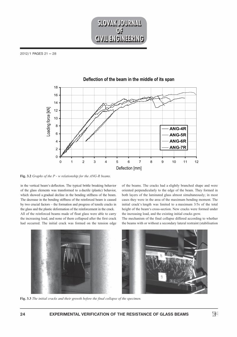
in theverticalbeam‘sdeflection.Thetypicalbrittlebreakingbehaviorof the glass elementswas transformed to aductile (plastic) behavior,whichshowedagradualdecline in thebendingstiffnessof thebeam.Thedecreaseinthebendingstiffnessofthereinforcedbeamiscausedbytwocrucialfactors–theformationandprogressoftensilecracksintheglassandtheplasticdeformationofthereinforcementinthecrack.Allofthereinforcedbeamsmadeoffloatglasswereabletocarrytheincreasingload,andnoneofthemcollapsedafterthefirstcrackhad occurred. The initial crack was formed on the tension edge
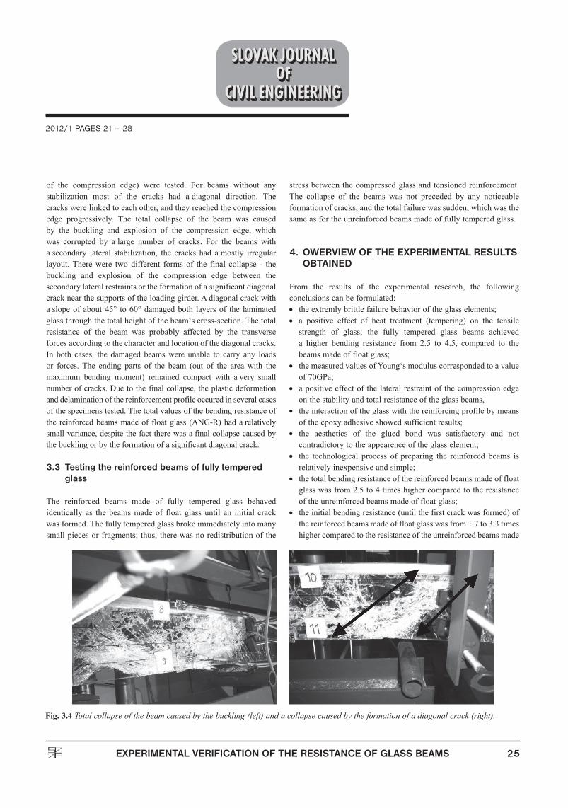
of thebeams.The crackshad aslightlybranched shape andwereorientedperpendicularly to theedgeof thebeam.Theyformed inboth layersof the laminatedglassalmost simultaneously; inmostcasestheywereintheareaofthemaximumbendingmoment.Theinitial crack‘slength was limited to amaximum 3/5s of the totalheightofthebeam‘scross-section.Newcrackswereformedundertheincreasingload,andtheexistinginitialcracksgrew.Themechanismofthefinalcollapsedifferedaccordingtowhetherthebeamswithorwithoutasecondarylateralrestraint(stabilisation
Fig. 3.2Graphs of the P - w relationship for the ANG-R beams.
Fig. 3.3The initial cracks and their growth before the final collapse of the specimen.
2012/1 PAGES 21 — 28
25EXPERIMENTAL VERIFICATION OF THE RESISTANCE OF GLASS BEAMS
of the compression edge) were tested. For beams without anystabilization most of the cracks had adiagonal direction. Thecrackswerelinkedtoeachother,andtheyreachedthecompressionedge progressively. The total collapse of the beam was causedby the buckling and explosion of the compression edge, whichwas corrupted by alarge number of cracks. For the beams withasecondary lateral stabilization, the cracks had amostly irregularlayout.Therewere twodifferent formsof the final collapse - thebuckling and explosion of the compression edge between thesecondarylateralrestraintsortheformationofasignificantdiagonalcracknearthesupportsoftheloadinggirder.Adiagonalcrackwithaslopeofabout45° to60°damagedboth layersof the laminatedglassthroughthetotalheightofthebeam‘scross-section.Thetotalresistance of the beam was probably affected by the transverseforcesaccordingtothecharacterandlocationofthediagonalcracks.In both cases, the damaged beamswere unable to carry any loadsor forces. The ending parts of the beam (out of the area with themaximum bending moment) remained compact with avery smallnumberofcracks.Duetothefinalcollapse,theplasticdeformationanddelaminationofthereinforcementprofileoccuredinseveralcasesofthespecimenstested.Thetotalvaluesofthebendingresistanceofthe reinforcedbeamsmadeof floatglass (ANG-R)hadarelativelysmallvariance,despitethefacttherewasafinalcollapsecausedbythebucklingorbytheformationofasignificantdiagonalcrack.
3.3 Testing the reinforced beams of fully tempered glass
The reinforced beams made of fully tempered glass behavedidenticallyas thebeamsmadeof floatglassuntil an initial crackwasformed.Thefullytemperedglassbrokeimmediatelyintomanysmallpiecesorfragments;thus,therewasnoredistributionofthe
stressbetweenthecompressedglassandtensionedreinforcement.The collapse of the beams was not preceded by any noticeableformationofcracks,andthetotalfailurewassudden,whichwasthesameasfortheunreinforcedbeamsmadeoffullytemperedglass.
4. OWERVIEW OF THE EXPERIMENTAL RESuLTS OBTAINED
From the results of the experimental research, the followingconclusionscanbeformulated:• theextremlybrittlefailurebehavioroftheglasselements;• a positive effect of heat treatment (tempering) on the tensilestrength of glass; the fully tempered glass beams achieveda higher bending resistance from 2.5 to 4.5, compared to thebeamsmadeoffloatglass;
• themeasuredvaluesofYoung‘smoduluscorrespondedtoavalueof70GPa;
• apositiveeffectofthelateralrestraintofthecompressionedgeonthestabilityandtotalresistanceoftheglassbeams,
• theinteractionoftheglasswiththereinforcingprofilebymeansoftheepoxyadhesiveshowedsufficientresults;
• the aesthetics of the glued bond was satisfactory and notcontradictorytotheappearenceoftheglasselement;
• the technological process of preparing the reinforced beams isrelativelyinexpensiveandsimple;
• thetotalbendingresistanceofthereinforcedbeamsmadeoffloatglasswasfrom2.5to4timeshighercomparedtotheresistanceoftheunreinforcedbeamsmadeoffloatglass;
• theinitialbendingresistance(untilthefirstcrackwasformed)ofthereinforcedbeamsmadeoffloatglasswasfrom1.7to3.3timeshighercomparedtotheresistanceoftheunreinforcedbeamsmade
Fig. 3.4Total collapse of the beam caused by the buckling (left) and a collapse caused by the formation of a diagonal crack (right).

26 EXPERIMENTAL VERIFICATION OF THE RESISTANCE OF GLASS BEAMS
2012/1 PAGES 21 — 28
offloatglass,butonly50to100%ofthetotalbendingresistanceoftheunreinforcedbeamsmadeoffullytemperedglass;
• allofthereinforcedbeamsmadeoffloatglassdidnotcollapseafterthefirstcrackhadoccurred;thus100%ofthepost-breakageload-bearingcapacitywasreached;
• theredistributionofthestressbetweenthecompressedglassandtensioned reinforcement developed after the crack‘s formation;amoresignificantincreaseinthenormalstresswasmeasuredinthereinforcement(stainlesssteelprofile);
• the typical brittle breaking behavior of the glass elementstransformed into ductile (plastic) behavior, which showedagradualdeclineinthebendingstiffnessofthebeam;
• a decrease in the bending stiffness of a reinforced beam iscausedby two crucial factors - the formation and extensionof
tensile cracks in the glass and the plastic deformation of thereinforcementatthepointofthecrack;
• noneofthespecimensfailedduetothedelaminationorruptureofthereinforcementprofile;allofthemcollapsedafterthefailureoftheglasspart,whichwascorruptedbyalargenumberofcracks;
• theapplicationofthereinforcementincombinationwiththefullytemperedglasswasineffectiveandhadnopracticalimportance;
• the increase in the total bending resistance of the reinforcedbeams compared to the unreinforced beams made of fullytemperedglasswasnegligibleinthetests(maximum10%);
• the total bending resistance of the reinforced beams made offully tempered glass compared to the reinforced beams of thefloatglasswasapproximately30%higher(thepositiveeffectoftemperingonthetensilestrengthoftheglass).
Fig. 4.2Maximal loading of the beams by total collapse (total resistance).
Fig. 4.1Total loading of the beams by the initial crack formation (initial resistance).

2012/1 PAGES 21 — 28
27EXPERIMENTAL VERIFICATION OF THE RESISTANCE OF GLASS BEAMS
5. THEORETICAL ANALYSIS
5.1 FEM models
Atotalof16modelswasanalysed in theFEMcalculationsusingtheDlubalRFEM4software.Thebehaviorofabeamwasanalysedboth in terms of the extent of abeam‘sdamage (without acrack,onecrack,anumberofcracks)andintermsoftheworkingdiagramofthereinforcementmaterial(thelinearandnon-linearrelationshipofσ - ε).Thenon-linearmaterialmodeloftheEN1.4301stainlesssteelusedasimplifiedworkingdiagramaccordingtoEC1993-1-4:2006(E).The original continuous dependence ofσ - ε was replaced in theFEMcalculationsbyapolygonal.ThelayerednatureofthelaminatedglasswasignoredintheFEMmodels; the laminatedglassandalso thereinforcingprofileswerereplacedbyashell element.Both theglass and reinforcement laytogetherononecommonplane.Inthecaseofthecrackedglassbeams,thetensilecrack/cracksweredefinedasFEMelementswith thenon-linearworkingdiagramoftheglassofawidthof5mm.Exceedingthenormalstressintensionover 1MPa caused arupture of the material, and these elementswerenolongercapableofcarryinganytensionforces.Inthecaseofnormalstressincompression,theunlimitedlinearbehaviorofthematerialwasdefined.
5.2 Overview of the theoretical results
The evaluation of the FEM calculations focused primarily onacomparisonoftheverticaldeflectionUz,thenormalstressSigmax
andthedistancebetweenthecompressionedgeandtheneutralaxisx.SeveralofthegraphicoutputsfromtheRFEM4softwareareshowninFig.5.1toillustratethetheoreticalresultsoftheFEMmodels.
5.3 Comparison of the results
The results of the FEM calculations proved that the number andextensionofcracksdonotaffectthebendingstiffnessofareinforced
Fig. 5.2Diagrams of the P – w relationship of the reinforced glass beams, a comparison of the theoretical and experimental results.
Fig. 5.1-Normal stress Sigmax in the glass and vertical deflection Uz for loading force P = 18kN (one crack, non-linear material model of the reinforcement).

28 EXPERIMENTAL VERIFICATION OF THE RESISTANCE OF GLASS BEAMS
2012/1 PAGES 21 — 28
glassbeamsignificantlyinthecaseoftheunlimitedlinearbehaviorofthereinforcementmaterial(thedashedtracesshowaslightvariance,Fig.5.2).Ontheotherhand,theeffectofthenumberandextensionofthecracksinglassisstronglymanifestedforanon-linearmaterialmodel of the reinforcement (continuous traces).Aglass beam hasavery smallbending stiffness, and theverticaldeflection increasesbecauseoftheplasticdeformationofthereinforcementinthecrack.Thecomparisonofthetheoretical(FEManalysis)andexperimentalresults indicates aplastic deformation of the reinforcement duringtheexperimentafterthecrackswereformed;otherwise,theductile(plastic) P – w relationship of the real diagram (with an almosthorizontalsecondarypartition)isnotpossible(Figs.3.2and5.2).Inmostcasesthereinforcementworkselasticallybeforetheinitialcrackformation;therefore,theresultsofthetheoreticalandexperimentalresearchonthereinforcedglassbeamswithoutcracksaresimilar.
6. CONCLuSION
Theissueofglassbeamsisarelativelynovelfieldforload-bearingstructures. Experimental research at the Department of Steel andTimberStructureshasshownthatthereliabilityofglassstructurescan be significantly improved by means of combinations withmetallic materials. Reinforcing glass with aglued stainless steelprofile increases its total resistance and supplies avery importantresidual resistance to the damaged glass structure (post-breakageload-bearing capacity). The application of the reinforcing profile
bymeansofepoxyadhesivesistechnologicallyaverysimpleandrelativelyinexpensiveprocess,whichisnotcontradictionarytotheappearance of aglass element. The unpredictable and dangerousbrittlebreakingbehavioroftheglasselementsismodifiedtowardstheductile (plastic)behavior.The significantdamageof theglassand large deformations is noticeable before the final collapseof the reinforced glass element occurs. The application of thereinforcement in combination with fully tempered glass has nopractical importance, because it immediately breaks into manysmallpieces;thus,thereisnopossibleredistributionoftheinternalforces, which leads to asudden failure of the beam without anypost-breakageload-bearingcapacity.Thetheoreticalanalysisprovidedhelpsinunderstandingtheoperationofreinforcedglassbeamsinageneralway.ThedeviationsbetweentheresultsoftheFEMcalculationsandtheexperimentaldatamainlyoccur because the mechanical material properties of the stainlesssteelwereconsideredaccordingtothetheoreticalECvalues,andtherealworkingdiagramof the reinforcementwasnotexperimentallytested.TheresultsoftheexperimentaltestingofthereinforcedglassbeamsshowedthattherealelasticworkingintervaloftheEN1.4301stainlesssteelusedwasprobablyhigherthanthetheoreticalnominalvalueoftheyieldstrengthfy=210MPa,accordingtotheEC.ThecomputationalFEMmodelsusedaregenerallyapplicableinthedesignofreinforcedglassbeamsdespitethedeviationslistedabove.Usingthenominalmaterialproperties,thetheoreticalresults(totalbendingresistance,verticaldeflection,normalstress)representsafevalues.
REFERENCES
[1] Slivanský, M.: Experimental and theoretical verification oftheresistanceofglassbeams.DissertationworkSvF-3237-3702,CivilEngineering,SUTBratislava2010
[2] Bos, F. P.: Towards acombined probabilistic/consequence-based safety approachof structural glassmembers,HERONVol.52,No.1/2,2007
[3] Flinterhoff,A.:Loadcarryingbehaviourofhybridsteel–glassbeams inbending,Master‘sThesis,UniversityofDortmund,InstituteofSteelConstruction,2003
[4] Freytag, B.: Glass – Concrete Composite Technology,StructuralEngineeringInternational2/2004,pp.111-117
[5] Grotepaß, B.:Application of hybrid steel – glass beams inmodernarchitecture,Master‘sThesis,UniversityofDortmund,InstituteofSteelConstruction,2006
[6] Hamm, J.:Tragverhalten vonHolz undHolzwerkstoffen imstatischenVerbundmitGlas,PhD.ThesisNo.2065, IBOIS/EPFL,2000
[7] Kreher,K.:TragverhaltenundBemessungvonHolz–GlassVerbundträgernunterBerücksichtigungderEigenspannungenimGlas,PhD.ThesisNo.2999,IBIOS/EPFL,2004
[8] Louter, C.: Adhesively bonded reinforced glass beams,HERONVol.52,Nos.1/2,2007
[9] Ølgaard, A. B., Nielsen, J. H., Olesen, J. F., Stang, H.:Properties of anAdhesive for StructuralGlassApplications,ChallengingGlass,ConferenceonArchitecturalandStructuralApplicationsofGlass,2008
[10] Palumbo, M.:ANew Roof for the XIIIth Century “LoggiadeVicari”BasedonStructuralGlassTrusses:ACaseStudy,GlassProcessingDays2005
[11] Wellershoff, F., Sedlacek, G.: Structural Use of Glass inHybridElements,Steel–GlassBeams,Glass–GFRPPlates,GlassProcessingDays2003,pp.268-270