research article home electrical appliances...
TRANSCRIPT

S. H. Husin et al., International Journal of Computer Science and Mobile Computing, Vol.2 Issue.9, September- 2013, pg. 85-91
© 2013, IJCSMC All Rights Reserved 85
Available Online at www.ijcsmc.com
International Journal of Computer Science and Mobile Computing
A Monthly Journal of Computer Science and Information Technology
ISSN 2320–088X
IJCSMC, Vol. 2, Issue. 9, September 2013, pg.85 – 91
RESEARCH ARTICLE
Home Electrical Appliances Smart System
S. H. Husin1, A. A. Ngahdiman2, N. M. Z. Hashim3, Y. Yusop4, A.S Ja’afar5 1, 2, 3, 4, 5 Faculty of Electronics & Computer Engineering, Universiti Teknikal Malaysia Melaka,
Malaysia [email protected]; [email protected]; [email protected]; [email protected];
[email protected] Abstract— A Smart Home is designed for the future home system that will be equipped with latest technology and given leisure for people. Hence the Smart Home will give a big impact in home design and will be the main target in a research and development (R&D) and business in the future. In this project Programmable Logic Controller (PLC) will be rolled as the primary control unit of the whole system. The main idea is about the new generation of homes. Smart homes are actually ordinary homes turned extraordinary using the latest technology. A smart home is nearly fully automated and it ensures safety, security and comfort for everyone under its roof. By utilizing advance and complex technologies, life is made easier and simpler. As a conclusion, this project was actually significantly can prevent problems that happened to present home automation system. This system will enable user to control their home appliances by using SMS. A web cam or CCTV for the capturing real time video are recommended to be in the future work as the user can also see the video from the distance. Keywords— Global System for Mobile Communications (GSM); Home Electrical Appliances, Programmable Logic Controller (PLC); Smart System; Short Messaging System (SMS)
I. INTRODUCTION In this communication technology era, many researches have been done to create a new technology that will
match to their needs in current lifestyle. The cost of the device might be influenced people before purchasing it. However there are some people who do not care about the price but always looking for its technology and the benefit of the product. As the people are now busy with their work and rarely have time at their home, a good monitoring system will the solution for this issue.
A Smart Home is designed for the future home system that will be equipped with latest technology and given leisure for people. Hence the Smart Home will give a big impact in home design and will be the main target in a research and development (R&D) and business in the future. In this project PLC will be rolled as the primary control unit of the whole system. The main idea is about the new generation of homes. Smart homes are actually ordinary homes turned extraordinary using the latest technology. A smart home is nearly fully automated and it ensures safety, security and comfort for everyone under its roof. By utilizing advance and complex technologies, life is made easier and simpler[1].
This project is proposed to develop a smart controlling system for home appliances by using Global System for Mobile Communications (GSM) [2], [3] and Programmable Logic Controller (PLC). The system is connected to the GSM modem by using communication interface. Input of the PLC is from the home main
S. H. Husin et al., International Journal of Computer Science and Mobile Computing, Vol.2 Issue.9, September- 2013, pg. 85-91
© 2013, IJCSMC All Rights Reserved 86
switch and the output is several of the home appliances [4], [5]. The GSM Modem is used for enabling people to remotely control the switching via Short Messaging System (SMS)[6].
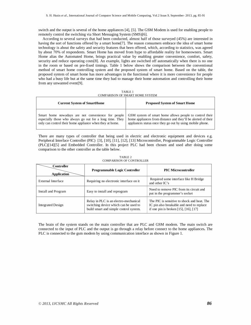
According to several surveys that had been conducted, almost half of those surveyed (45%) are interested in having the sort of functions offered by a smart home[7]. The reason consumers embrace the idea of smart home technology is about the safety and security features that been offered, which, according to statistics, was agreed by about 70% of respondents. Smart Home has moved from hype to affordable reality for homeowners. Smart Home alias the Automated Home, brings practical value by enabling greater convenience, comfort, safety, security and reduce operating costs[8]. An example, lights are switched off automatically when there is no one in the room or based on pre-fixed timings. Table 1 below shows the comparison between the conventional method of smart home controlling system and the proposed system of smart home. Based on the table, the proposed system of smart home has more advantages in the functional where it is more convenience for people who had a busy life but at the same time they had to manage their home automation and controlling their home from any unwanted event[9].
TABLE 1
COMPARISON OF SMART HOME SYSTEM
Current System of SmartHome
Proposed System of Smart Home
Smart home nowadays are not convenience for people especially those who always go out for a long time. They only can control their home appliance when they at home.
GSM system of smart home allows people to control their home appliances from distance and they’ll be alerted of their appliances status once they go out by using mobile phone.
There are many types of controller that being used in electric and electronic equipment and devices e.g. Peripheral Interface Controller (PIC) [3], [10], [11], [12], [13] Microcontroller, Programmable Logic Controller (PLC)[14][5] and Embedded Controller. In this project PLC had been chosen and used after doing some comparison to the other controller as the table below.
TABLE 2
COMPARISON OF CONTROLLER
The brain of the system stands on the main controller that are PLC and GSM modem. The main switch are connected to the input of PLC and the output is go through a relay before connect to the home appliances. The PLC is connected to the gsm modem by using communication interface as shown in Figure 1.
Controller
Application Programmable Logic Controller PIC Microcontroller
External Interface Requiring no electronic interface on it Required some interface like H Bridge and other IC’s
Install and Program Easy to install and reprogram Need to remove PIC from its circuit and put in the programmer’s socket
Integrated Design Relay in PLC is an electro-mechanical switching device which can be used to build smart and simple control system.
The PIC is sensitive to shock and heat. The IC pin also breakable and need to replace if one pin is broken [15], [16], [17]

S. H. Husin et al., International Journal of Computer Science and Mobile Computing, Vol.2 Issue.9, September- 2013, pg. 85-91
© 2013, IJCSMC All Rights Reserved 87
Fig. 1 Layout design of smart home automation by using GSM Modem
Fig. 1 shows that the current are flowed from the switch to the input of the PLC. Then, GSM modem will process the signals from user’s phone and send the data to the communication interface. The communications interface will process the signal and send to PLC. After the program is executed the PLC it will permit the current to go through the output and to the relay coil. Then the relay coil will trigger the current into the load.
The aim of this project are to develop a system that notify user the current status of electrical appliances by using GSM communication , to help the user by avoiding any cases of accident caused by electrical appliances, and to improve the available system in market [18], [19], [20].
II. METHODOLOGY A. Overall Flow Chart
Project is implemented by several processes as shown in Fig. 2 below.
Fig. 2 Flowchart of Smart Home Automation by Using GSM

S. H. Husin et al., International Journal of Computer Science and Mobile Computing, Vol.2 Issue.9, September- 2013, pg. 85-91
© 2013, IJCSMC All Rights Reserved 88
B. Design Development 1) Testing the Circuit Connection
After the layout of the circuit is completed, the circuit is tested in order to confirm the circuit is in good the
condition or not. There are two ways to do the circuit testing:
a) Physical appearance checking and testing
By using this method, the connection of the hardware can be determined whether complete or not and the jumper and cable are placed at its proper place.
b) Using the multimeter
This method is to see clearly the connection by touching the probes at the circuit track for testing. Usually the
unit at multimeter is set at x 1 ohm. If the circuit has the connection, the meter reader show at the zero while if no connection, the multimeter will show to the infinity. C. Software Development
The Multisim, Trilogy Programmer and Zelio RTSR programmer software are been used in this project. Multisim is used to design the layout for the Hardware. After the ladder program is done, the coding is compiled and programmed into the PLC. In this process the Trilogy Programmer and the Zelio RTSR programmer will be used.
III. RESULT A. Hardware Result
All the components for the circuit are installed properly according to its position. After the installation was
completed, the components are connected by using jumper and three core cables as shown in Fig. 3 below.
Figure 3 Relay that will trigger load with high current For the model, the parts that been used to completed this project are Lamp, Switch, GSM Modem, PLC and
Communication Interface and 24V Relay.

S. H. Husin et al., International Journal of Computer Science and Mobile Computing, Vol.2 Issue.9, September- 2013, pg. 85-91
© 2013, IJCSMC All Rights Reserved 89
Fig. 4 Completed project model Fig 4 shows the completed project model for the system. From the switch, the current will be flow into the
control box. The control box which contains the PLC, communications interface, GSM modem and relay coil will trigger the current to the load when receives the signal from the user.
B. Software Result
Ladder logic programs mimic the electrical circuit diagrams used for wiring control systems in the electrical
industry. The basic purpose of an electrical control system is to determine whether a load should be turned ON or turned OFF, under what circumstances and when it should happen. The fundamental element of a ladder diagram is a "Contact". A contact has only two states that are open or closed. An open contact breaks the current flow whereas a closed contact allows current to flow through it to the next element. The simplest contact is an ON/OFF switch, which requires external force (e.g. the human hand) to activate it. Limit switches are those small switches that are placed at certain location so that when a mechanical device moves towards it, the contact will be closed and when the device moves away from it, the contact will be opened. If a contact is connected to a load and the contact is closed, the load will be turned ON. For this project, the connection from the switch to the load is illustrated by ladder diagram as follow:
Fig. 5 Ladder diagram for the switch and load
In Fig. 5 the vertical line on the left is the "Power" line; current must flow through the "Switch" contact in
order to turn ON the load "Lamp". Here the user has the two way controlling system that can send the SM to them. Three switches should be
working together in order to control the lamp. A Master switch must be ON, and also one of the two control switches "controlsw1" and "controlsw2" must be ON while the other must be OFF in order to turn ON the lamp. All 3 switches are wired to 3 inputs of the PLC and the lamp to the output of the plc. The ladder program to perform this task is shown in Fig. 6 below.
Fig. 6 Ladder diagram for two way controlling system
In Fig. 6 a contact with a "/" across its body is a Normally-Closed (N.C.) contact which the ladder program is
using the "inverse" of the logic state of the input to interpret the diagram. Hence in the above ladder diagram, if "Master" and "controlSW1" are turned ON but "controlSW2" is turned OFF, the lamp will be turned ON since

S. H. Husin et al., International Journal of Computer Science and Mobile Computing, Vol.2 Issue.9, September- 2013, pg. 85-91
© 2013, IJCSMC All Rights Reserved 90
the inverse logic state of an OFF state "controlSW2" is true. Think of an imaginary current flowing through the "Master" contact, then through the "controlSW1" and finally through the normally-closed "controlSW2" contact to turn ON the lamp.
On the other hand, if "controlSW1" is OFF but "controlSW2" is ON, the lamp is also turned ON because the current could flow via "Master" and then through the lower parallel branch via N.C. "controlSW1" and the N.O. "controlSW2". A contact can also be activated by the presence of an electrical current. This makes it possible for a control system to control the turning ON or OFF of a large load by using electrical current to activate a switch that can conduct high current. The simplest form of this type of contact is a relay. Ladder Logic programming language borrows some of those terms used to describe the electromagnetic relay for its own use. The user connects a relay coil to the right end of the ladder diagram just like an output, as shown in Fig. 7.
Fig. 7 Ladder diagram to trigger relay coil In traditional electromagnetic relay, a coil of wire is wound around an iron core that turns it into an
electromagnet. When current passes through the "coil" the magnet is "energized" and the force is used to either close a contact or open it (that will be a normally-closed contact since it is closed when not energized).
IV. CONCLUSIONS As a conclusion, this project was actually significantly can prevent problems that happened to present home
automation system. This system will enable user to control their home appliances by using SMS. Cost would not be a problem to users because if this product became commercial, the cost will be lower than this project cost due to the research and development and the hardware pricing that always decreased from time to time. As for future improvement, some futures should be added are e.g. to have visual connection to the user by sending the multimedia messages (MMS) by sending the picture or video about what are really happens at home when they are out from home. This is because nowadays the 4G technology are widely used and most area in this country has the coverage. Hence it will be more practically used as a webcam or CCTV for the capturing real time video as the user can also see the video from the distance. The function of the sensor also should be implemented in this system. The sensor will detect unwanted events like fire or smoke and flood. As a result when the house on a fire or there were water pipe leaking of flood, it will notify the user as soon as possible to enable user respond quickly before it become worst.
ACKNOWLEDGMENT We are grateful to Universiti Teknikal Malaysia Melaka (UTeM) for their kind help for supplying the
electronic components and giving their laboratory facility to complete this study.
REFERENCES [1] Advance Electronic Project for your home and Automobile, Second. PROMPT Publication, 1998, pp. 67–
70. [2] “GSM Technologies.” [Online]. Available: http://en.wikipedia.org/wiki/GSM. [3] N. M. Z. Hashim, N. B. Hamdan, Z. Zakaria, R. A. Hamzah, and A. Salleh, “Flood Detector Emergency
Warning System,” International Journal Of Engineering And Computer Science (IJECS), vol. 2, no. 8, pp. 2332–2336, 2013.
[4] S. K. Subramaniam, S. H. Husin, S. A. Anas, and A. H. Hamidon, “Multiple Method Switching System for Electrical Appliances using Programmable Logic Controller,” vol. 4, no. 6, pp. 243–252, 2009.
[5] N. M. Z. Hashim, N. M. T. N. Ibrahim, Z. Zakaria, F. Syahrial, and H. Bakri, “Development New Press Machine using Programmable Logic Controller,” International Journal Of Engineering And Computer Science (IJECS), vol. 2, no. 8, pp. 2310–2314, 2013.

S. H. Husin et al., International Journal of Computer Science and Mobile Computing, Vol.2 Issue.9, September- 2013, pg. 85-91
© 2013, IJCSMC All Rights Reserved 91
[6] M. Sikandar, H. Khiyal, A. Khan, and E. Shehzadi, “SMS Based Wireless Home Appliance Control System ( HACS ) for Automating Appliances and Security Preliminaries Home Appliance Control System ( HACS ),” Issue s In Science and Information Technology, vol. 6, pp. 887–894, 2009.
[7] “Market study shows positive demand for Smart Home Solutions.” [Online]. Available: http://smarthomepartnering.com/cms/?p=63.
[8] S. K. Subramaniam, S. H. Husin, R. S. S. Singh, and A. H. Hamidon, “Industrial Shop Floor Performance,” vol. 3, no. 1, pp. 28–35, 2009.
[9] “Smart Home.” [Online]. Available: http://en.wikipedia.org/wiki/Smarthome. [10] Martin P. Bates, PIC Microcontroller. An Introduction to Microelectronic, Third. ELSVIER, p. 289. [11] N. M. Z. Hashim, N. A. Ali, A. S. Jaafar, N. R. Mohamad, L. Salahuddin, and N. A. Ishak, “Smart
Ordering System via Bluetooth,” International Journal of Computer Trends and Technology (IJCTT), vol. 4, no. 7, pp. 2253–2256, 2013.
[12] N. M. Z. Hashim, N. A. Ali, A. Salleh, A. S. Ja, and N. A. Z. Abidin, “Development of Optimal Photosensors Based Heart Pulse Detector,” International Journal of Engineering and Technology (IJET), vol. 5, no. 4, pp. 3601–3607, 2013.
[13] N. M. Z. Hashim, S. H. Husin, A. S. Ja, and N. A. A. Hamid, “Smart Wiper Control System,” International Journal of Application or Innovation in Engineering & Management (IJAIEM), vol. 2, no. 7, pp. 409–415, 2013.
[14] PLC Beginners Guide, 1st ed. Omron Asia PAcific Pte Ltd, 1999, pp. 1–4. [15] N. M. Z. Hashim, A. F. Jaafar, Z. Zakaria, A. Salleh, and R. A. Hamzah, “Smart Casing for Desktop
Personal Computer,” International Journal Of Engineering And Computer Science (IJECS), vol. 2, no. 8, pp. 2337–2342, 2013.
[16] N. M. Z. Hashim, A. S. Jaafar, N. A. Ali, L. Salahuddin, N. R. Mohamad, and M. A. Ibrahim, “Traffic Light Control System for Emergency Vehicles Using Radio Frequency,” IOSR Journal of Engineering (IOSRJEN), vol. 3, no. 7, pp. 43–52, 2013.
[17] N. M. Z. Hashim and M. S. Sizali, “Wireless Patient Monitoring System,” International Journal of Science and Research (IJSR), vol. 2, no. 8, pp. 250–255, 2013.
[18] N. M. Z. Hashim and N. A. M. M. Arifin, “Laboratory Inventory System,” International Journal of Science and Research (IJSR), vol. 2, no. 8, pp. 261–264, 2013.
[19] N. M. Z. Hashim, N. H. Mohamad, Z. Zakaria, H. Bakri, and F. Sakaguchi, “Development of Tomato Inspection and Grading System using Image Processing,” International Journal Of Engineering And Computer Science (IJECS), vol. 2, no. 8, pp. 2319–2326, 2013.
[20] N. M. Z. Hashim and S. N. K. S. Mohamed, “Development of Student Information System,” International Journal of Science and Research (IJSR), vol. 2, no. 8, pp. 256–260, 2013.