research article effect of modified pin profile and
TRANSCRIPT

Research ArticleEffect of Modified Pin Profile and Process Parameters onthe Friction Stir Welding of Aluminum Alloy 6061-T6
J. C. Verduzco Juárez,1 G. M. Dominguez Almaraz,1
R. García Hernández,2 and J. J. Villalón López1
1Facultad de Ingenierıa Mecanica, Universidad Michoacana de San Nicolas de Hidalgo (UMSNH), Santiago Tapia No. 403,Col. Centro, 58000 Morelia, MICH, Mexico2Instituto de Investigaciones Metalurgicas, UMSNH, Edificio U, Ciudad Universitaria, Gral. Francisco J. Mugica S/N,Felicitas del Rıo, 58030 Morelia, MICH, Mexico
Correspondence should be addressed to G. M. Dominguez Almaraz; [email protected]
Received 10 August 2016; Revised 27 September 2016; Accepted 4 October 2016
Academic Editor: Hongchao Kou
Copyright © 2016 J. C. Verduzco Juarez et al. This is an open access article distributed under the Creative Commons AttributionLicense, which permits unrestricted use, distribution, and reproduction in any medium, provided the original work is properlycited.
This work deals with the effect of a new “bolt-head” pin profile on the friction stir welding performance of the aluminum alloy6061-T6, compared to traditional pin profiles. Friction stir welding parameters such as the tool rotation speed and the weldingspeed were investigated together with the different pin profiles; the results show that the new “bolt-head” pin profile leads to bettermechanical properties of welded specimens.The pin profiles used in this work were the straight square (SS), straight hexagon (SH),taper cylindrical (TC), and the straight hexagon “bolt-head” (SHBH). It was found that the last pin profile improves the materialflow behavior and the uniform distribution of plastic deformation and reduces the formation of macroscopic defects on the weldedzone. Mechanical tensile tests on welded specimens were performed to determine the tensile strength: the specimens welded withthe SHBH pin profile have shown the highest mechanical properties. An approach is presented for material flow on this aluminumalloy using the SHBH pin profile, which is related to the improvement on the resulting mechanical properties.
1. Introduction
The alloy 6061-T6 is the most popular and used of allaluminum alloys; it presents an adequate balance of mechan-ical properties, cost, and weight. This alloy is used foraerospace and automotive industries under joining andwelding requirements [1–4]. The traditional fusion weldingmethods, such as MIG and TIG, are characterized by highheat dissipation and the transformations of microstructuralphases, leading to a number of defects (microporosities, lessfine equiaxed recrystallized grain) and thermic instabilities(hardening precipitates), on the joining elements [5, 6].For aeronautical application of the 6061-T6 alloy, the laserwelding leads to high mechanical properties (reduction ofFZ and HAZ, even if porosity may be promoted) and goodfinishing [7, 8]; however, the cost is a principal constraint forthis welding method.
Friction stir welding is a solid state welding techniquewhich has been developed at the end of 1991 by “TheWeldingInstitute” in the United Kingdom [9]. A nonconsumablerotating tool communicates energy to the two facing surfaces,which may be of the same metallic alloy or different metal-lic alloys. The rotating movement and the related frictiongenerate heat dissipation between the two facing surfaces,leading to softening of this region and facilitating the highshear plastic deformation and mixing of the material [10–12].
It has been recognized that the principal parametersaffecting the bonding strength of FSW and the resultingmicrostructure are the rotational speed of tool, the weldingspeed, the axial tool force, and the angle of tool in regard tothe welding surface (tilt angle) [13, 14].
The application of this joining technique has been widelyused for the aluminum alloy 6061-T6 [15–19]; nevertheless, inthis work is presented the effect of a new profile of the pin tool
Hindawi Publishing CorporationAdvances in Materials Science and EngineeringVolume 2016, Article ID 4567940, 9 pageshttp://dx.doi.org/10.1155/2016/4567940
2 Advances in Materials Science and Engineering
to improve the mechanical properties on this material, afterthe friction stir welding.
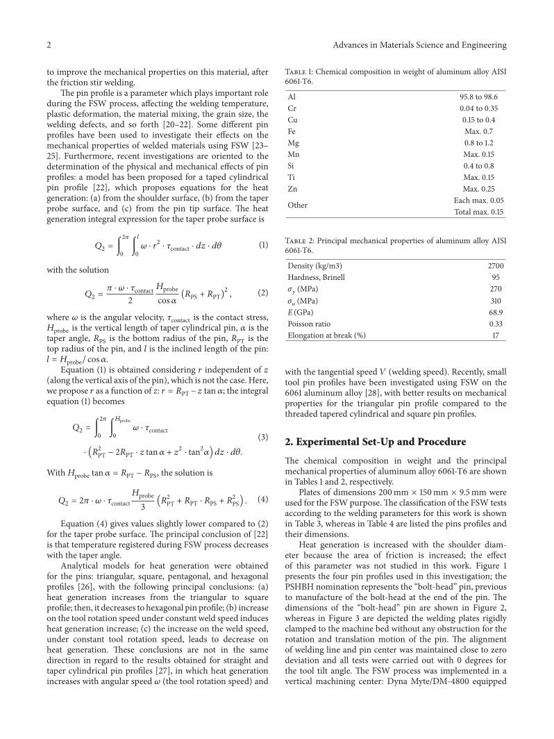
The pin profile is a parameter which plays important roleduring the FSW process, affecting the welding temperature,plastic deformation, the material mixing, the grain size, thewelding defects, and so forth [20–22]. Some different pinprofiles have been used to investigate their effects on themechanical properties of welded materials using FSW [23–25]. Furthermore, recent investigations are oriented to thedetermination of the physical and mechanical effects of pinprofiles: a model has been proposed for a taped cylindricalpin profile [22], which proposes equations for the heatgeneration: (a) from the shoulder surface, (b) from the taperprobe surface, and (c) from the pin tip surface. The heatgeneration integral expression for the taper probe surface is
𝑄2 = ∫2𝜋
0∫𝑙
0𝜔 ⋅ 𝑟2 ⋅ 𝜏contact ⋅ 𝑑𝑧 ⋅ 𝑑𝜃 (1)
with the solution
𝑄2 = 𝜋 ⋅ 𝜔 ⋅ 𝜏contact2𝐻probecos𝛼 (𝑅PS + 𝑅PT)
2 , (2)
where 𝜔 is the angular velocity, 𝜏contact is the contact stress,𝐻probe is the vertical length of taper cylindrical pin, 𝛼 is thetaper angle, 𝑅PS is the bottom radius of the pin, 𝑅PT is thetop radius of the pin, and 𝑙 is the inclined length of the pin:𝑙 = 𝐻probe/ cos𝛼.
Equation (1) is obtained considering 𝑟 independent of 𝑧(along the vertical axis of the pin), which is not the case. Here,we propose 𝑟 as a function of z: 𝑟 = 𝑅PT −𝑧 tan 𝛼; the integralequation (1) becomes
𝑄2 = ∫2𝜋
0∫𝐻probe
0𝜔 ⋅ 𝜏contact
⋅ (𝑅2PT − 2𝑅PT ⋅ 𝑧 tan𝛼 + 𝑧2 ⋅ tan2𝛼) 𝑑𝑧 ⋅ 𝑑𝜃.(3)
With𝐻probe tan𝛼 = 𝑅PT − 𝑅PS, the solution is
𝑄2 = 2𝜋 ⋅ 𝜔 ⋅ 𝜏contact𝐻probe3 (𝑅
2PT + 𝑅PT ⋅ 𝑅PS + 𝑅2PS) . (4)
Equation (4) gives values slightly lower compared to (2)for the taper probe surface. The principal conclusion of [22]is that temperature registered during FSW process decreaseswith the taper angle.
Analytical models for heat generation were obtainedfor the pins: triangular, square, pentagonal, and hexagonalprofiles [26], with the following principal conclusions: (a)heat generation increases from the triangular to squareprofile; then, it decreases to hexagonal pin profile; (b) increaseon the tool rotation speed under constant weld speed inducesheat generation increase; (c) the increase on the weld speed,under constant tool rotation speed, leads to decrease onheat generation. These conclusions are not in the samedirection in regard to the results obtained for straight andtaper cylindrical pin profiles [27], in which heat generationincreases with angular speed 𝜔 (the tool rotation speed) and
Table 1: Chemical composition in weight of aluminum alloy AISI6061-T6.
Al 95.8 to 98.6Cr 0.04 to 0.35Cu 0.15 to 0.4Fe Max. 0.7Mg 0.8 to 1.2Mn Max. 0.15Si 0.4 to 0.8Ti Max. 0.15Zn Max. 0.25
Other Each max. 0.05Total max. 0.15
Table 2: Principal mechanical properties of aluminum alloy AISI6061-T6.
Density (kg/m3) 2700Hardness, Brinell 95𝜎𝑦 (MPa) 270𝜎𝑢 (MPa) 310E (GPa) 68.9Poisson ratio 0.33Elongation at break (%) 17
with the tangential speed 𝑉 (welding speed). Recently, smalltool pin profiles have been investigated using FSW on the6061 aluminum alloy [28], with better results on mechanicalproperties for the triangular pin profile compared to thethreaded tapered cylindrical and square pin profiles.
2. Experimental Set-Up and Procedure
The chemical composition in weight and the principalmechanical properties of aluminum alloy 6061-T6 are shownin Tables 1 and 2, respectively.
Plates of dimensions 200mm × 150mm × 9.5mm wereused for the FSW purpose.The classification of the FSW testsaccording to the welding parameters for this work is shownin Table 3, whereas in Table 4 are listed the pins profiles andtheir dimensions.
Heat generation is increased with the shoulder diam-eter because the area of friction is increased; the effectof this parameter was not studied in this work. Figure 1presents the four pin profiles used in this investigation; thePSHBH nomination represents the “bolt-head” pin, previousto manufacture of the bolt-head at the end of the pin. Thedimensions of the “bolt-head” pin are shown in Figure 2,whereas in Figure 3 are depicted the welding plates rigidlyclamped to the machine bed without any obstruction for therotation and translation motion of the pin. The alignmentof welding line and pin center was maintained close to zerodeviation and all tests were carried out with 0 degrees forthe tool tilt angle. The FSW process was implemented in avertical machining center: Dyna Myte/DM-4800 equipped

Advances in Materials Science and Engineering 3
Table 3: Classification of FSW tests, according to the welding parameters.
Nominationtest
Toolrotational
speed (rpm)
Weldingspeed
(mm/min)
Penetrationspeed
(mm/min)
Axial force(kN)
Used pinprofile
C1 800 40 3 8 SS, SHBHC2 1000 90 9 8 TC, SHBHC3 1200 90 9 8 SH, SHBH
Table 4: Models for the pins according to the tool profile, the material, and dimensions.
Models Pin profile Shoulder surface Material Pin length (mm) Shoulder diameter (mm)M1 SS Flat Steel 4140 9 19M2 TC Flat Steel 4140 9 19M3 SH Flat Steel 9840 9 25.4M4 SHBH Flat Steel H-13 9 25.4
TC SS SH PSHBH SHBH
Figure 1: Manufactured pin profiles for the FSW process.
409
34
33.5
∅11
8
2.2
4.08
AA
E
Sect
ion
A-A
Det
ail E 12
R10.50
∅25.40
Figure 2: Dimensions (mm) for the “bolt-head” pin profile.
with Mitsubishi controls and a maximum tool rotation of6000 rpm.
The testing specimens were obtained from the weldedplates in perpendicular direction in regard to the FSWline for the tests: tensile, hardness, and the microstructuralobservation by optical microscope. Tensile specimens weremanufactured according to the norm ASTM-E8M, with agauge length of 64mm, a gauge width of 6mm, and athickness of 9.5mm, as shown in Figure 4.
All tensile tests were carried out on a tension machinemodel Zwick/Roell Z100 with 100KN of maximum testload and at constant test displacement of 6mm/min. Themicrohardness Mitutoyo model HM 200 was used to obtainthe hardness profiles along the welding zone with an applied
load of 0.1 Kg and 10 sec of time application. In addition,the FSW welding process was obtained under the followingcondition: the distance between the tip of pin and the bottomof the welding workpiece was 0.3mm.
3. Results and Discussions
Plates of thickness 9.5mm of aluminum alloy 6061-T6 werejoined by FSW technique using classical pin profiles (SS, SH,and TC) and the new pin profile “bolt-head” to comparethe results on welding and mechanical properties [29]. InFigure 5 are illustrated the different zones, from 1 to 8, alongthe welding line from which the tensile specimens have beenmachined. This figure shows the welding direction as well as
4 Advances in Materials Science and Engineering
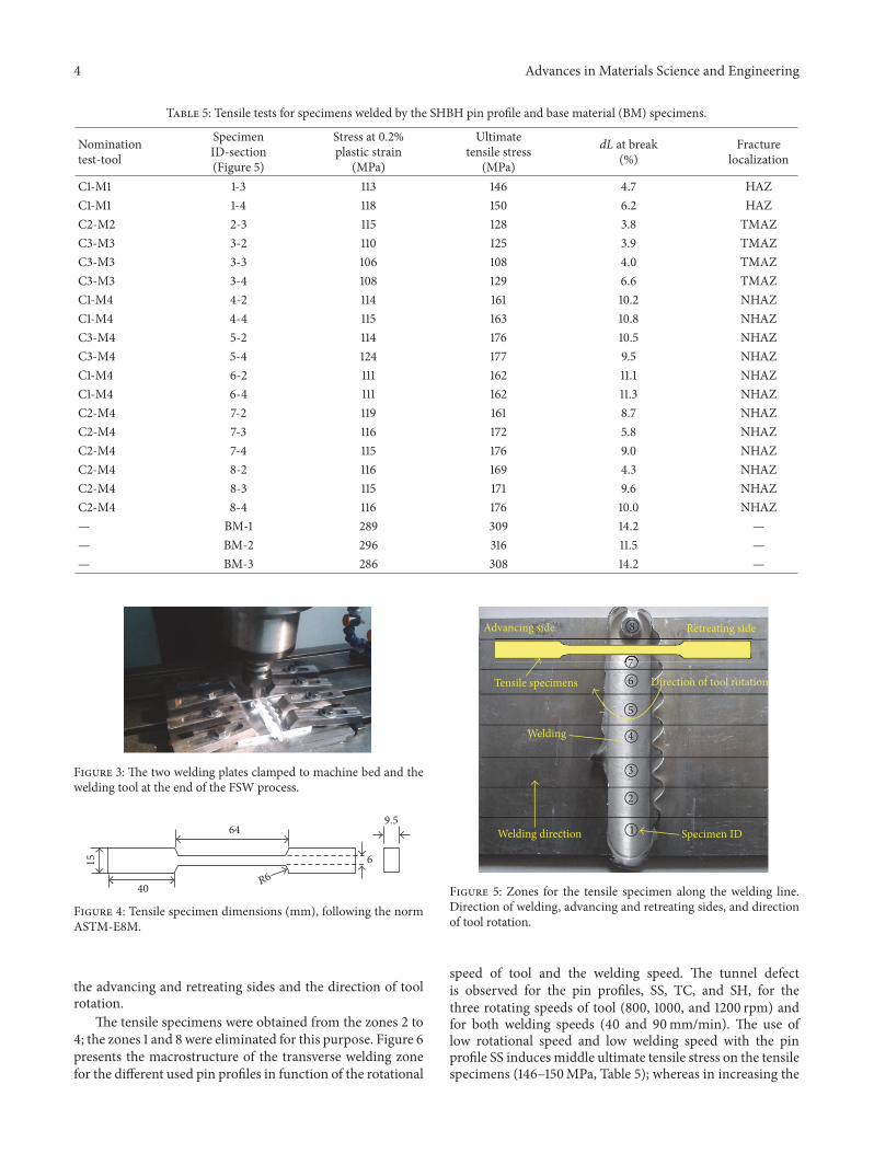
Table 5: Tensile tests for specimens welded by the SHBH pin profile and base material (BM) specimens.
Nominationtest-tool
SpecimenID-section(Figure 5)
Stress at 0.2%plastic strain
(MPa)
Ultimatetensile stress
(MPa)
dL at break(%)
Fracturelocalization
C1-M1 1-3 113 146 4.7 HAZC1-M1 1-4 118 150 6.2 HAZC2-M2 2-3 115 128 3.8 TMAZC3-M3 3-2 110 125 3.9 TMAZC3-M3 3-3 106 108 4.0 TMAZC3-M3 3-4 108 129 6.6 TMAZC1-M4 4-2 114 161 10.2 NHAZC1-M4 4-4 115 163 10.8 NHAZC3-M4 5-2 114 176 10.5 NHAZC3-M4 5-4 124 177 9.5 NHAZC1-M4 6-2 111 162 11.1 NHAZC1-M4 6-4 111 162 11.3 NHAZC2-M4 7-2 119 161 8.7 NHAZC2-M4 7-3 116 172 5.8 NHAZC2-M4 7-4 115 176 9.0 NHAZC2-M4 8-2 116 169 4.3 NHAZC2-M4 8-3 115 171 9.6 NHAZC2-M4 8-4 116 176 10.0 NHAZ— BM-1 289 309 14.2 —— BM-2 296 316 11.5 —— BM-3 286 308 14.2 —
Figure 3: The two welding plates clamped to machine bed and thewelding tool at the end of the FSW process.
40
15
64
R6
6
9.5
Figure 4: Tensile specimen dimensions (mm), following the normASTM-E8M.
the advancing and retreating sides and the direction of toolrotation.
The tensile specimens were obtained from the zones 2 to4; the zones 1 and 8 were eliminated for this purpose. Figure 6presents the macrostructure of the transverse welding zonefor the different used pin profiles in function of the rotational
1
3
4
6
5
7
8
2
Advancing side Retreating side
Tensile specimens
Welding direction Specimen ID
Direction of tool rotation
Welding
Figure 5: Zones for the tensile specimen along the welding line.Direction of welding, advancing and retreating sides, and directionof tool rotation.
speed of tool and the welding speed. The tunnel defectis observed for the pin profiles, SS, TC, and SH, for thethree rotating speeds of tool (800, 1000, and 1200 rpm) andfor both welding speeds (40 and 90mm/min). The use oflow rotational speed and low welding speed with the pinprofile SS induces middle ultimate tensile stress on the tensilespecimens (146–150MPa, Table 5); whereas in increasing the

Advances in Materials Science and Engineering 5
W1
W2
W3
W4
W5
W6
M4M1
C1
C2
C3
M2 M4
M3 M4
1 cm
Figure 6: Tunnel defect for welding specimens using different pin profiles, for three tool rotating speeds and two welding speeds.
last two velocities and using the pin profiles TC and SH, theultimate tensile stress decreases as shown on the same table.The maximum ultimate tensile stress is obtained with theSHBHpin profile (176-177MPa), using high values for the twoweld speeds.
Concerning the tunnel defect in the welded specimens,it is present for the three pin profiles, SS, TC, and SH, asshown in Figure 6; nevertheless, this defect is eliminatedusing the SHBH pin profile for all rotating and weldingused speeds, as depicted in the same figure. An attemptto explain the causes that induce the elimination of tunneldefect with the use of SHBH pin profile is undertaken in thelast section. These results seem to agree with the physicalconditions close to the contact zone between the pin andthe welding material: the heat generation increases when thetool rotation speed increases; then, the flow ofmaterial acrossthe welding thickness increases too. For tapered pin profilesparticularly, the contact area of pin decreases with the depthof the welding thickness and the flow of material increasesacross the thickness, contributing to tunnel defect.
In Table 5 are listed the tensile tests for the weldedspecimens using the four pin profiles, as well as the tensiletests on the base material (last three specimens in this table).The ultimate tensile stress for the welded specimens rangesfrom 108 to 177MPa, whereas for the base material thesevalues range from 308 to 316MPa [30, 31].
Figure 7 presents the tensile tests graphs for the weldedspecimens and the base material with the following identifi-cation in regard to Table 5: C1-M1 =W1-3 (146MPaUTS); C2-M2 = W2-3 (128MPa UTS); C3-M3 = W3-3 (108MPa UTS);C1-M4 = W4-3 (163MPa UTS); C2-M4 = W5-4 (176MPaUTS); C3-M4 = W6-4 (177MPa UTS). In all cases fortensile tests on welded specimens, the higher values for UTSwere obtained with the SHBH pin profile. Furthermore, thefracture sites under tensile tests of welded SHBH specimenswere located outside the welding zone, as shown in Figure 8.
Figure 9 presents the Vickers microhardness measuredalong theweld cross-section comprising the zones: the nuggetzone (NZ), the thermomechanical heat zone (TMHZ), theheat affected zone (HAZ), and the base metal (BM), for
the welded SHBH specimens. The higher values of thismechanical property have been obtained for low rotationspeed during the FSW process and intermediate values forwelding speed; this tendency has been mentioned by someauthors [32, 33], for aluminum alloys.
Fracture surfaces for the tensile specimens are shown inFigure 10: the corresponding fracture surface for specimenscontaining the tunnel defect is depicted in Figure 10(a),whereas the fracture surface for specimen without the tunneldefect is presented in Figure 10(b). Figure 10(c) shows thefracture surface for the base material. Low plastic defor-mation characterizes the separation of fracture surfaces forspecimens with tunnel defect, revealing that low resistance isopposed to tensile loading: this behavior is represented by thetensile tests W2-3 and W3-3 in Figure 7.
The increase of plastic strain is related to the ductilefracture and the microvoids coalescence, which is observedon this aluminum alloy for tensile specimens presentinghigher resistance, as illustrated on Figures 10(b) and 10(c). Inthis case, the peripheral plastic deformation zone increaseswith the UTS of tensile test on this material, as it is observedin the last two figures. The central zone of fracture surfacesfor specimens without tunnel defect is typified by low or nullplastic deformation and a granular nondeformedmicrostruc-ture [34].
The material flow during the FSW process is a principalfactor influencing the presence of welding defects, suchas cavities, root flaws, and kissing bond [35]. Generallyspeaking, the material flow in FSW is determined by threedifferent motions: (a) the material flow beneath and deeperof the tool shoulder, from and to the root of the probe, (b)the flow of material along the pin surface, downward in thevertical direction, and (c) the material flow from the bottomof pin towards the shoulder, away from the pin surface; thisflow interacts with the two precedents flows [36, 37].
A swirl is present in the advancing side which increaseswith the welding speed and induces the radial motionillustrated, whereas in the retreating side the radial motionis considerably reduced and may change direction accordingto the welding parameters and the testing material [38, 39].

6 Advances in Materials Science and Engineering
Tens
ile st
ress
(MPa
)
Strain (%)0 0
0
50
100
150
0
50
100
150
2 24 48 8 106
W1-3
W2-3
W3-3
Tens
ile st
ress
(MPa
)
Strain (%)
W5-4 W4-3
W6-4
Tens
ile st
ress
(MPa
)
Strain (%)
BM
300
200
100
00 2 4 8 10 12 146
Figure 7: Tensile tests for welded and base material specimens.
Fracture zone outside the weld
UTS
UTS
UTSC2-M4 176 MPa
C2-M4 171 MPa
C2-M4 169 MPa
Figure 8: Localization of fracture under tensile tests for the SHBHwelded specimens.
In Figure 11 are represented the three mentioned flows,contributing to the flow of material during the weldingprocess by FSW.
The flow of material along the pin surface and in thedownwards vertical direction is reduced using the SHBH pin
Mic
roha
rdne
ss H
V
Distance from the weld center (mm)
NZ TMAZ HAZ BM
1101051009590858075706560555045403530
TMAZHAZBM
−7
−6.5
−6
−5.5
−5
−4.5
−4
−3.5
−3
−1.5
−1
−0.5 0
0.5 1
1.5 2
2.5 3
3.5 4
4.5 5
5.5 6
6.5 7
−2
−2.5
1000 rpm, 90mm/min, SHBH (C2-M4)1000 rpm, 90mm/min, SHBH (C2-M4)800 rpm, 40mm/min, SHBH (C1-M4)
Figure 9: Vickers microhardness along the welding zone for theSHBH welded specimens.
profile, whereas the flow from the bottom of pin towardsthe shoulder is moved more away from the pin surface. The

Advances in Materials Science and Engineering 7
(a) (b)
(c)
Figure 10: Fracture surfaces for tensile specimens: (a) with tunnel defect, (b) without tunnel defect, and (c) for the base material.
Retreating side
Flow of material, motion (a)Flow of material, motion (b) Flow of material, motion (c)
Advancing side
Figure 11:Material flows on the SHBHpin profile according to threeprincipal motions.
bolt-head at the end of the pin reduces considerably thematerial flow in vertical direction: themechanical effect is thereduction of discontinuities on the material with the rotatingand the advancingmotion, which leads to reduction of tunneland other defects in this aluminum alloy. The vertical flow isassociated with the continuity of material along the verticaldirection during local FSW stirring; the reduction of thisflow by the pin bolt-head induces the reduction of materialdiscontinuity and hence welding defects.
4. Conclusion
In this work is presented a new pin profile denominated bolt-head, for the friction stir welding of the aluminum alloy 6061-T6. The tensile and hardness tests show that this pin profileimproves such mechanical properties of the welded alloy.Additional conclusions related to this work are as follows:
(a) No tunnel defect was observed on the welded speci-mens using the SHBH pin profile, for the three rotat-ing speeds and two welding speeds of experimentaltesting.
(b) A modified expression is proposed to calculate heatgeneration from the taper probe surface.
(c) The fracture for tensile specimens, using the SHBHpin profile, took place systematically outside thewelding zone.
(d) The Vickers microhardness along the welding zonefor the SHBH welded specimens was higher whenusing low rotational speeds of tool, for the testingwelding speeds [40].
(e) Low plastic deformation is observed for the fracturesurfaces of specimens with tunnel defect, indicatingthat low resistance is opposed during the tensile tests.The fracture surface of tensile specimens withouttunnel defect shows appreciable plastic deformationaround the peripheric rectangular area, indicatingresistance of material to tensile loading.

8 Advances in Materials Science and Engineering
(f) The bolt-head at the end of the pin reduces thematerial flow downward, contributing to reduction orelimination of the tunnel and other defects.
(g) Further investigations will be undertaken in thefuture to assess the effect of the bolt-head profile onthe mechanical properties of joining materials by theFSW method, particularly, the heat generation, thematerial flow, modification of the bolt-head profile,the welding of other materials than aluminum alloys,and so forth.
Competing Interests
The authors declare that they have no competing interests.
Acknowledgments
The authors express their gratitude to the University ofMichoacan in Mexico for the facilities received in the devel-opment of this work. A special mention of gratitude wasmade to CONACYT (The National Council for Science andTechnology,Mexico) for the financial support destined to thisstudy by the Program Grant CB-241117-2014.
References
[1] F. Fadaeifard, F. Gharavi, K. A. Matori, A. R. Daud, M. K.Ariffin, and M. Awang, “Investigation of microstructure andmechanical properties of friction stir lap welded AA6061-T6 invarious welding speeds,” Journal of Applied Sciences, vol. 14, no.3, pp. 221–228, 2014.
[2] L. Liu, H. Nakayama, S. Fukumoto, A. Yamamoto, and H.Tsubakino, “Microscopic observations of friction stir welded6061 aluminum alloy,”Materials Transactions, vol. 45, no. 2, pp.288–291, 2004.
[3] W. S. Miller, L. Zhuang, J. Bottema et al., “Recent developmentin aluminium alloys for the automotive industry,” MaterialsScience and Engineering: A, vol. 280, no. 1, pp. 37–49, 2000.
[4] A. Heinz, A. Haszler, C. Keidel, S. Moldenhauer, R. Benedictus,and W. S. Miller, “Recent development in aluminium alloys foraerospace applications,” Materials Science and Engineering A,vol. 280, no. 1, pp. 102–107, 2000.
[5] S. Jannet, K. Mathews, and R. Raja, “Comparative investiga-tion of friction stir welding and fusion welding of 6061 T6-5083 O aluminum alloy based on mechanical properties andmicrostructure,” Bulletin of the Polish Academy of Sciences:Technical Sciences, vol. 62, no. 4, pp. 791–795, 2014.
[6] R. Adalarasan and R. M. Santhanakumar, “Parameter design infusion welding of AA 6061 aluminium alloy using desirabilitygrey relational analysis (DGRA)method,” Journal ofThe Institu-tion of Engineers (India): Series C, vol. 96, no. 1, pp. 57–63, 2015.
[7] A. El-Batahgy and M. Kutsuna, “Laser beam welding ofAA5052, AA5083, and AA6061 aluminum alloys,” Advances inMaterials Science and Engineering, vol. 2009, Article ID 974182,9 pages, 2009.
[8] D. Narsimhachary, R. N. Bathe, G. Padmanabham, and A.Basu, “Influence of temperature profile during laser weldingof aluminum alloy 6061 T6 on microstructure and mechanicalproperties,”Materials and Manufacturing Processes, vol. 29, no.8, pp. 948–953, 2014.
[9] W. M. Thomas, E. D. Nicholas, J. C. Needham, M. G. Murch,P. Temple-Smith P, and C. J. Dawes, “Friction-stir butt welding,GB Patent No. 9125978.8,” International patent application No.PCT/GB92/02203, 1991.
[10] W. Woo and H. Choo, “Softening behaviour of friction stirwelded Al 6061-T6 and Mg AZ31B alloys,” Science and Technol-ogy of Welding and Joining, vol. 16, no. 3, pp. 267–272, 2011.
[11] P. Zhang, N. Guo, G. Chen et al., “Plastic deformation behaviorof the friction stir welded AA2024 aluminum alloy,” TheInternational Journal of Advanced Manufacturing Technology,vol. 74, no. 5–8, pp. 673–679, 2014.
[12] T. Debroy, A. De, H. K. D. H. Bhadeshia, V. D. Manvatkar,and A. Arora, “Tool durability maps for friction stir weldingof an aluminium alloy,” Proceedings of the Royal Society A:Mathematical, Physical and Engineering Sciences, vol. 468, no.2147, pp. 3552–3570, 2012.
[13] M. Indira Rani, R. N. Marpu, and A. C. S. Kumar, “A study ofprocess parameters of friction stir welded AA 6061 aluminumalloy in O and T6 conditions,”ARPN Journal of Engineering andApplied Sciences, vol. 6, no. 2, pp. 61–66, 2011.
[14] R. Nandan, T. DebRoy, and H. K. D. H. Bhadeshia, “Recentadvances in friction-stir welding—process, weldment structureand properties,” Progress in Materials Science, vol. 53, no. 6, pp.980–1023, 2008.
[15] S. Rajakumar, C. Muralidharan, and V. Balasubramanian,“Establishing empirical relationships to predict grain size andtensile strength of friction stir welded AA 6061-T6 aluminiumalloy joints,” Transactions of Nonferrous Metals Society of China(English Edition), vol. 20, no. 10, pp. 1863–1872, 2010.
[16] W. Woo, H. Choo, D. W. Brown, Z. Feng, and P. K. Liaw,“Angular distortion and through-thickness residual stress dis-tribution in the friction-stir processed 6061-T6 aluminumalloy,” Materials Science and Engineering A, vol. 437, no. 1, pp.64–69, 2006.
[17] W. H. Jiang and R. Kovacevic, “Feasibility study of frictionstir welding of 6061-T6 aluminium alloy with AISI 1018 steel,”Proceedings of the Institution of Mechanical Engineers, Part B:Journal of Engineering Manufacture, vol. 218, no. 10, pp. 1323–1331, 2004.
[18] L. E. Murr, G. Liu, and J. C. McClure, “A TEM study of precip-itation and related microstructures in friction-stir-welded 6061aluminium,” Journal ofMaterials Science, vol. 33, no. 5, pp. 1243–1251, 1998.
[19] S. Rajakumar, C. Muralidharan, and V. Balasubramanian, “Pre-dicting tensile strength, hardness and corrosion rate of frictionstir welded AA6061-T6 aluminium alloy joints,” Materials andDesign, vol. 32, no. 5, pp. 2878–2890, 2011.
[20] R. Palanivel, P. KoshyMathews, N. Murugan, and I. Dinaharan,“Effect of tool rotational speed and pin profile on microstruc-ture and tensile strength of dissimilar friction stir weldedAA5083-H111 and AA6351-T6 aluminum alloys,”Materials andDesign, vol. 40, pp. 7–16, 2012.
[21] K. Elangovan, V. Balasubramanian, and M. Valliappan, “Influ-ences of tool pin profile and axial force on the formationof friction stir processing zone in AA6061 aluminium alloy,”International Journal of Advanced Manufacturing Technology,vol. 38, no. 3-4, pp. 285–295, 2008.
[22] V. S. Gadakh and K. Adepu, “Heat generation model for tapercylindrical pin profile in FSW,” Journal ofMaterials Research andTechnology, vol. 2, no. 4, pp. 370–375, 2013.
[23] M. K. Sued, D. Pons, J. Lavroff, and E. H. Wong, “Designfeatures for bobbin friction stir welding tools: development

Advances in Materials Science and Engineering 9
of a conceptual model linking the underlying physics to theproduction process,”Materials and Design, vol. 54, pp. 632–643,2014.
[24] M. Ilangovan, S. Rajendra Boopathy, and V. Balasubrama-nian, “Effect of tool pin profile on microstructure and tensileproperties of friction stir welded dissimilar AA 6061-AA 5086aluminium alloy joints,” Defence Technology, vol. 11, no. 2, pp.174–184, 2015.
[25] K. Ramanjaneyulu, G.MadhusudhanReddy, A. Venugopal Rao,and R.Markandeya, “Structure-property correlation of AA2014friction stir welds: role of tool pin profile,” Journal of MaterialsEngineering and Performance, vol. 22, no. 8, pp. 2224–2240,2013.
[26] V. S. Gadakh, A. Kumar, and G. J. Vikhe Patil, “Analyticalmodeling of the friction stir welding process using different pinprofiles,”Welding Journal, vol. 94, no. 4, pp. 115–124, 2015.
[27] S. Tikader, P. Biswas, and A. B. Puri, “A study on tooling and itseffect on heat generation and mechanical properties of weldedjoints in friction stir welding,” Journal of The Institution ofEngineers (India): Series C, vol. 2016, 12 pages, 2016.
[28] H. I. Dawood, K. S. Mohammed, A. Rahmat, and M. B.Uday, “Effect of small tool pin profiles on microstructures andmechanical properties of 6061 aluminum alloy by friction stirwelding,” Transactions of Nonferrous Metals Society of China,vol. 25, no. 9, pp. 2856–2865, 2015.
[29] G. M. Dominguez Almaraz, J. C. Verduzco Juarez, R. GarcıaHernandez, and J. J. Villalon Lopez, “Friction stir welding onaeronautical aluminumalloy 6061-T6,” inProceedings of the 25thInternational Materials Research Congress (IMRC ’16), Cancun,Mexico, August 2016.
[30] D. Ortiz, M. Abdelshehid, R. Dalton et al., “Effect of cold workon the tensile properties of 6061, 2024, and 7075 Al alloys,”Journal of Materials Engineering and Performance, vol. 16, no.5, pp. 515–520, 2007.
[31] T. Yokoyama, K. Nakai, and K. Katoh, “Tensile properties ofAA6061-T6 friction stir welds and constitutive modeling intransverse and longitudinal orientations,” Journal of Light MetalWelding and Construction, vol. 53, no. 8, pp. 19–28, 2015.
[32] N. Rajamanickam and V. Balusamy, “Effects of process parame-ters onmechanical properties of friction stir welds using designof experiments,” Indian Journal of Engineering and MaterialsSciences, vol. 15, no. 4, pp. 293–299, 2008.
[33] A. Karam, T. S. Mahmoud, H. M. Zakaria, and T. A. Khalifa,“Friction stir welding of dissimilar A319 and A413 cast alu-minum alloys,”Arabian Journal for Science and Engineering, vol.39, no. 8, pp. 6363–6373, 2014.
[34] A. Dorbane, G. Ayoub, B. Mansoor, R. Hamade, G. Kridli,and A. Imad, “Observations of the mechanical response andevolution of damage of AA 6061-T6 under different strain ratesand temperatures,” Materials Science and Engineering: A, vol.624, pp. 239–249, 2015.
[35] H.-B. Chen, K. Yan, T. Lin, S.-B. Chen, C.-Y. Jiang, and Y. Zhao,“The investigation of typical welding defects for 5456 aluminumalloy friction stir welds,” Materials Science and Engineering A,vol. 433, no. 1-2, pp. 64–69, 2006.
[36] C. Hamilton, S. Dymek, andM. Blicharski, “Amodel ofmaterialflow during friction stir welding,” Materials Characterization,vol. 59, no. 9, pp. 1206–1214, 2008.
[37] Q. Yang, S. Mironov, Y. S. Sato, and K. Okamoto, “Materialflow during friction stir spot welding,” Materials Science andEngineering A, vol. 527, no. 16-17, pp. 4389–4398, 2010.
[38] X. He, F. Gu, and A. Ball, “A review of numerical analysis offriction stir welding,” Progress in Materials Science, vol. 65, pp.1–66, 2014.
[39] R. S. Mishra and Z. Y. Ma, “Friction stir welding and process-ing,” Materials Science and Engineering R: Reports, vol. 50, no.1-2, pp. 1–78, 2005.
[40] J. S. Leon and V. Jayakumar, “Investigation of mechanical prop-erties of aluminium 6061 alloy friction stir welding,” AmericanJournal of Mechanical Engineering and Automation, vol. 1, no. 1,pp. 6–9, 2014.

Submit your manuscripts athttp://www.hindawi.com
ScientificaHindawi Publishing Corporationhttp://www.hindawi.com Volume 2014
CorrosionInternational Journal of
Hindawi Publishing Corporationhttp://www.hindawi.com Volume 2014
Polymer ScienceInternational Journal of
Hindawi Publishing Corporationhttp://www.hindawi.com Volume 2014
Hindawi Publishing Corporationhttp://www.hindawi.com Volume 2014
CeramicsJournal of
Hindawi Publishing Corporationhttp://www.hindawi.com Volume 2014
CompositesJournal of
NanoparticlesJournal of
Hindawi Publishing Corporationhttp://www.hindawi.com Volume 2014
Hindawi Publishing Corporationhttp://www.hindawi.com Volume 2014
International Journal of
Biomaterials
Hindawi Publishing Corporationhttp://www.hindawi.com Volume 2014
NanoscienceJournal of
TextilesHindawi Publishing Corporation http://www.hindawi.com Volume 2014
Journal of
NanotechnologyHindawi Publishing Corporationhttp://www.hindawi.com Volume 2014
Journal of
CrystallographyJournal of
Hindawi Publishing Corporationhttp://www.hindawi.com Volume 2014
The Scientific World JournalHindawi Publishing Corporation http://www.hindawi.com Volume 2014
Hindawi Publishing Corporationhttp://www.hindawi.com Volume 2014
CoatingsJournal of
Advances in
Materials Science and EngineeringHindawi Publishing Corporationhttp://www.hindawi.com Volume 2014
Smart Materials Research
Hindawi Publishing Corporationhttp://www.hindawi.com Volume 2014
Hindawi Publishing Corporationhttp://www.hindawi.com Volume 2014
MetallurgyJournal of
Hindawi Publishing Corporationhttp://www.hindawi.com Volume 2014
BioMed Research International
MaterialsJournal of
Hindawi Publishing Corporationhttp://www.hindawi.com Volume 2014
Nano
materials
Hindawi Publishing Corporationhttp://www.hindawi.com Volume 2014
Journal ofNanomaterials