research article characteristics analysis of joint
TRANSCRIPT

Research ArticleCharacteristics Analysis of Joint Acoustic Echo and NoiseSuppression in Periodic Drillstring Waveguide
Li Cheng12 Chang Jinfeng12 Liu Zhao12 Fan Shangchun12 and Ding Tianhuai3
1 State Key Laboratory of Virtual Reality Technology and System Beihang University Beijing 100191 China2 Science and Technology on Inertial Laboratory Beihang University Beijing 100191 China3Department of Precision Instruments and Mechanology Tsinghua University Beijing 100086 China
Correspondence should be addressed to Li Cheng lcbj163com
Received 2 January 2014 Revised 11 April 2014 Accepted 28 April 2014 Published 11 May 2014
Academic Editor Kenneth J Loh
Copyright copy 2014 Li Cheng et alThis is an open access article distributed under the Creative CommonsAttribution License whichpermits unrestricted use distribution and reproduction in any medium provided the original work is properly cited
A newmethod of wireless data telemetry used by oil industry uses compressional acoustic waves to transmit downhole informationfrom the bottom hole to the surface Unfortunately acoustic echoes and drilling vibration noises in periodic drillstring are a majorissue in transmission performance A combined acoustic echo and noise suppression method based on wave motion characteristicin drillstring is adopted to enhance an upward-going transmitted acoustic signal The presented scheme consists of a primaryacoustic echo canceller using an array of two accelerometers for dealing with the downward-going noises and a secondary acousticinsulation structure for restraining the upward-going vibration noises Furthermore the secondary acoustic insulation structureexhibits a banded and dispersive spectral structure because of periodic groove configuration By using a finite-differential algorithmfor the one-dimensional propagation of longitudinal waves acoustic receiving characteristics of transmitted signals are simulatedwith additive Gaussian noise in a periodic pipe structure of limited length to investigate the effects on transmission performanceoptimizationThe results reveal that the proposed scheme can achieve amuch lower error bit ratio over a specified acoustic isolationfrequency range with a 30ndash40 dB reduction in the average noise level compared to traditional single-receiver scheme
1 Introduction
In the oil industry measurement-while-drilling (MWD)surveying is of great importance for the successful completionof the drilling process [1] Such information if transmit-ted to the surface can be used to optimize the drillingby adjusting the direction of drilling and to understanddownhole formation conditions in real time [2] Theseuseful data related to subsurface earth formation can bederived in a number of ways [3] The common approachesare referred to as either MWD or logging while drilling(LWD) because downhole information may be acquiredquicker and at lower cost by use of such techniques [4]Currently the telemetry methods available for MWD andLWD tools primarily include mud pulse telemetry extremelylow-frequency electromagnetic (EM) telemetry high-speedwired pipe telemetry and drillstring acoustic telemetry Themud pulse telemetry is the most commercially successful
method However the data transmission rate is limited toa few bits per second due to attenuations and spreadingof pulses When highly compressible underbalanced drillingfluid is used such an approach may become ineffective [5]EM telemetry has been considered for MWD services butEM signals also encounter high attenuation in regions oflow formation resistivity in cased holes and where bore-hole fluid is highly conductive Namely it is considered tohave limited range depends on characteristics especiallyresistivity of the formations surrounding the borehole andalso has limited data rates [6] High-speed wired pipetelemetry can be implemented by using a unique systemof wired drill pipes and associated drilling tools connectingthe MWD string to the surface Because special drill pipesand special tool joint connectors are required the cost ofthe drilling operation will be substantially increased Thedata transmission along the drillstring via acoustic stresswaves offers another communication possibility As early as
Hindawi Publishing CorporationShock and VibrationVolume 2014 Article ID 741314 10 pageshttpdxdoiorg1011552014741314
2 Shock and Vibration
1948 acoustic telemetry was identified as a potential methodfor high-speed communication In fact the drillstring doesnot have a uniform cross-sectional area and individualpipes are joined together at 10 meter intervals with heavythreaded couplings [7] Therefore the transmission charac-teristics exhibit a banded and dispersive structure based onthe theoretical analysis of an idealized drillstring presentedby Barnes and Kirkwood in 1972 [8] Compared with theother transmission methods drillstring acoustic telemetryhas the advantages to potentially provide high data rateand to be relatively unaffected by the formation propertiesFurthermore a uniquemultinode acoustic telemetry networkcapable of transmitting data at over 30 bits per secondhas been developed and successfully deployed in drillingapplication [9] In this case drillstringwaves can bemeasuredfor the transmission of information from the drill bit tothe surface Unfortunately a serious problem related to thetransmission of acoustic data while drilling is that ongoingdrilling operations tend to generate wide bandwidth noisewhich contaminates the acoustic data transmission channelthrough which acoustic data are being transferred Onesource of such noises is the drill bit typically located at theend of the drillstring which will generate stronger upward-going drilling noises interfering with the required upwardtravelling acoustic data Another is the top drive or othermechanical equipment located at the surface and coupled tothe drillstring which will generate downward-going surfacenoises interfering with the uplink acoustic data Due to theacoustic nature the transmitted acoustic data are disturbedby short- and long-period reverberations produced by themultiple reflections occurring in the drillstring Regardlessof the source thereof such noises strongly deteriorate thesignal-to-noise ratio (SNR) thereby making the data difficultto identify and analyze for this type of acoustic telemetryTherefore acoustic echo and noise suppression is a morecritical problem at multiple acoustic impedance mismatchpositions in drillstring where acoustic waves travel freely upand down the drillstring and confuse the transmission data
With regard to the aforementioned problem the theoret-ical models and schemes concerning acoustic echo or down-hole noise suppression have been independently studied tosome extent As far as acoustic echo cancellation is concernedRector and Marion used a data-dependent deconvolutionoperator to perform the inverse filtering of the multipleacoustic reflections [10] which may cause signal distortionsdue to coherent noise in surface measurements Drumhellerand Scott demonstrated a hardware design method of echosuppression using a novel digital time delay circuit and apair of spaced sensors such as strain gages or accelerometers[11]The exact time-delay control of travelling waves betweenthe two sensors and adaptive filters is required in thismethod Poletto presented a dual-sensor-based reverberationsuppression analysis method by measuring acceleration andstrain with opposite reflection coefficients [12] Addition ofthe dual waves makes it possible to remove part of thedrillstring reflections but it is prone to reduce the one-wayreflection noise fromone end of drillstringwhen the receiversare at intermediate positions Sinanovic et al described atheoretical channel model and analyzed two-receiver scheme
that exploited the fact that the dominant surface noise sourceand the signal respectively propagate in up and downdirections [13] Different delays between the two signals attwo receivers are exploited to suppress the downlink surfacenoise by applying appropriate filters in this model Howeverit only takes into account first-order wave reflections atthe pipe ends for simplicity and will become complicatedwhen multiple reflections are considered Besides downholenoise from drill bit tends to generate wide bandwidth noisewhich degrades the acoustic transmission performance ofdata Meehan demonstrated that a baffle filter comprisinga periodic structure of typically 20m interposed above orbelow the acoustic sub can reduce the effects of drill bitnoise onmodulated torsional wave [14] However the schemedoes not address the more serious problem of downlinkwave being reflected in a relatively unattenuated way back tothe transmitter where it may deteriorate the uplink acoustictelemetry wave According to the wave reflection phenomenacaused by acoustic impedance mismatches Drumheller etal disclosed an acoustic isolator containing multiple tubularmembers in series connection to mitigate the potentiallydestructive reflections from interfering with the up wave[15] This disclosed scheme requires the application of tun-ing bars whose lengths differ from an odd multiple of aquarter wavelength of a representative acoustic wave anddownhole noise isolator in a predetermined range of acousticfrequencies is not considered Then Shah et al introducedmultiple dampening members including one or a group oftwo or more nested cylindrical sleeves in radial directionto configure a low-frequency downhole acoustic attenuatorto weaken acoustic signals at frequencies below 5 kHz [16]but a complicated acoustic insulation structure (AIS) isrequired and especially its radial dimension is yet confinedby drilled borehole size Several other patents have alsobeen presented on acoustic isolators but most of them arespecially used for seismic signal transmitted through theformations instead of acoustic signal induced in drillstringFurthermore their acoustic models physical structures andsound insulation performance are not provided in detailIn this paper considering the effects of downholesurfacenoises and periodic drillstring channel an improved jointecho cancellation and noise suppressionmethod is developedto optimize the communication signal received at the receiverbased onmultiple extensional wave transmission characteris-tics in uplink and downlink drillstring channel
2 Method Architecture
The application of acoustic telemetry in real-time drillingsituations is much more challenging This is primarily dueto the increased noise from surface equipment and drillingoperations and the problem of unwanted acoustic wavereflections associatedwith beam-like drillstring structure anddownhole components such as the bottom-hole assembly(BHA) typically attached to the end of the drillstring [17]The drill bit crushes the formation and creates compressionalacoustic waves propagating in the drillstring Normal drillingoperations also produce in-band acoustic noise at multiple
Shock and Vibration 3
Rig
Surface noise
AEC Retrieved signal
Downhole
Downhole
Surface
Downlink
Drillstringchannel
Tool joint
Drill pipesTransmitterAcoustic isolator
BHADrill bit noise
Bit
S1S2
Uplink
Figure 1 Schematic view of the proposed model
sources at intensities comparable to the acoustic transduceroutput The surface noise from surface drilling operationsfurther degrades the signal sent by the transmitter We usethe idealized model as depicted in Figure 1 to analyze theperformance of acoustic telemetry
According to the schematic model two acoustic receiversmay be positioned at or near the top end of a drillstring at thesurface in the well Both the bit noise 119899119889(119905) and surface noise119899119904(119905) seriously confuse the transmission of original excitationsignal 119909(119905) during the drilling On one hand the noise119899119889(119905) travelling upward along the BHA is mixed with theoutput signal of the transmitter On the other hand the noise119899119904(119905) travelling downward along the drillstring is received bythe receiver Considering the fact that compressional acousticwaves travel in two directions in the drillstring the mixedreverberation signal formed by acoustic signals 119909(119905) 119899119889(119905)and 119899119904(119905) reaches the receiver in the multiple-path drill pipesIn accordance with the uplink and downlink transmissionpaths of acoustic waves an acoustic echo canceller (AEC) andanAIS are respectively introduced at the sides of receiver andthe transmitter as shown in Figure 1 to obtain higher SNR andlower bit error ratio (BER)
21 Use of Dual Waves for Cancelling Downlink EchoesAcoustic telemetry signals are disturbed by multiple rever-berations produced by the reflections occurring at acousticimpedance mismatch positions Dual measurements recordreflected waves travelling in the same direction and makeit possible to remove reflections of drillstring waves andunwanted noises For simplicity the effects of drill bit noise119899119889(119905) and corresponding acoustic isolator are ignored Refer-ring to Figure 2 for simplicity the two acoustic receivers1198781 and 1198782 spaced one-quarter wavelength of the carrierfrequency apart are placed on the first pipe at the top ofthe drillstring to record two signals 119899119904(119905) and 119909(119905) andtheir reflections The noise 119899119904(119905) consists of the direct surfacenoise as well as the downlink echoes of mixed signals from
Uplink wave Top endBottom end
Down link waveDrill pipe Tool joint
DrillstringSurface
The first pipe
x(t) ns(t)S1S2
1205824
Figure 2 Schematic diagram of the AEC using two receivers
the direct surface noise and the original excitation signal119909(119905) As a result of the standing wave theory the receiver1198781 is located approximately near the top end of drillstringand the lower receiver 1198782 is 1205824 away from the receiver 1198781Considering the effects of multiple reflections in drillstringchannel the uplink and downlink channel responses areintroduced in the proposed model Assuming that a unitpulse excitation is imparted on the bottom end of drillstringthe pulse excitation responses obtained by the receivers 1198781and 1198782 are respectively defined as ℎ1(119905) and ℎ2(119905) Similarlyassuming that a unit pulse excitation is imparted on the topend of drillstring the pulse excitation responses collected byboth receivers are respectively defined as ℎ1015840
1(119905) and ℎ
1015840
2(119905)
Accordingly in terms of the channel model in Figure 2 theresulting signals 1199101 and 1199102 at the receivers 1198781 and 1198782 are
1199101 (119905) = 119909 (119905) lowast ℎ1 (119905) + 119899119904 (119905) lowast ℎ1015840
1(119905)
1199102 (119905) = 119909 (119905) lowast ℎ2 (119905) + 119899119904 (119905) lowast ℎ1015840
2(119905)
(1)
By fast Fourier transform (FFT) algorithm (1) is writtenas
1198841 (119891) = 1198671198831
(119891)119883 (119891) + 1198671198731
(119891)119873119904 (119891)
1198842 (119891) = 1198671198832
(119891)119883 (119891) + 1198671198732
(119891)119873119904 (119891)
(2)
4 Shock and Vibration
Table 1 Dimensions of drillstring and single acoustic isolator
Structure Component Cross-sectional area (m2) Length (m)
Drillstring Drill pipe 339 times 10minus3 911
Tool joint 162 times 10minus3 0475
Acoustic isolator Groove The same as pipe body 119871119892 (determined by simulation)Convex portion The same as tool joint 119871 119888 (determined by simulation)
where1198671198831
(119891) 1198671198832
(119891)1198671198731
(119891) and1198671198732
(119891) are the Fouriertransforms of the functions ℎ1(119905) ℎ2(119905) ℎ
1015840
1(119905) and ℎ1015840
2(119905) in the
frequency domain respectivelySince the downwardmoving noise 119899119904(119905) disturbing acous-
tic signal extraction is a mixed signal of the noise and thedata due to multiple reflections the following result canbe achieved by (2) to minimize the amount of noise beingtransmitted upward towards the surface
119883(119891) =
1198671198732
(119891) 1198841 (119891) minus 1198671198731
(119891) 1198842 (119891)
1198671198831
(119891)1198671198732
(119891) minus 1198671198832
(119891)1198671198731
(119891)
(3)
It should be mentioned that the functions ℎ1(119905) andℎ2(119905) in (1) can be determined in model simulations bysolving the transient responses at two acoustic receivers 1198781and 1198782 according to the one-dimensional extensional wavepropagation equation in a periodic drillstring when a unitimpulse excitation is applied to the bottom end of drillstringLikewise the functions ℎ1015840
1(119905) and ℎ1015840
2(119905) can also be confirmed
when a unit impulse excitation is applied to the top end ofdrillstring In this way119867119883
1
(119891)1198671198832
(119891)1198671198731
(119891) and1198671198732
(119891)
may be obtained by the Fourier transforms In additionthe corresponding uplink and downlink channel responsesin communication channel between surface receiver anddownhole transmitter in real applications are sampled aftera known chirp signal is generated at the downhole trans-mitter and the surface location of drillstring respectivelyThe channel transfer function may be determined by cross-correlating the received signal with the reference chirp signalusing a frequency spectrum of the received signal and afrequency spectrum of the reference chirp signal Basedon the determined transfer function the functions 119867119883
1
(119891)1198671198832
(119891)1198671198731
(119891) and1198671198732
(119891) in (3) may be eventually solvedWith inverse Fourier transform the original excitation
signal 119909(119905) can be computed by
119909 (119905) = Fminus1(
1198671198732
(119891) 1198841 (119891) minus 1198671198731
(119891) 1198842 (119891)
1198671198831
(119891)1198671198732
(119891) minus 1198671198832
(119891)1198671198731
(119891)
) (4)
Then the recovered signal 119909(119905) detected by dual receiverswill be processed with a band-pass filter so that the frequencycontent is limited to the passband or bands which are used fordata transmission Also it can eliminate the high-frequencycontent introduced by the algorithm computation
22 Acoustic Isolator for Suppressing Uplink Downhole NoiseAs mentioned above downhole noise is also of concern inacoustic telemetry A traditional response to this problemwould be to place the acoustic telemetry device above
Drillcollar
Groove ConvexDrillpipes
Sound insulation structure
Lg Lc
Hollow tubular
Figure 3 Structure diagram of a single acoustic isolator
the BHA and simply direct the acoustic energy up thedrillstring away from the BHA components Unfortunatelytypical acoustic transmitters emit waves of equal magnitudein both ldquouprdquo and ldquodownrdquo directions and the downward travel-ling waves in particular may be reflected resulting in destruc-tive interference with the upward travelling waves In viewof the banded spectral response characteristics of periodicdrillstring a single AIS with periodic annular grooves foracoustic insulation is designed analogously as demonstratedin Figure 3 on basis of the principle of mechanical vibrationisolation
It can be inserted between the transmitter and drill collarto impede unwanted strong reflections to the transmitter andsubsequent to the receiver From Figure 3 acoustic insulationperformance of acoustic isolator is related to the length119871119892 of groove the length 119871119888 of the convex portion betweenadjacent grooves and the number 119873 of grooves Accordingto the acoustic insulation theory in acoustic logging in thispaper both the lengths 119871119892 and 119871119888 are set equal to one-quarter wavelength of the carrier frequency so that thecenter frequency to achieve the optimal noise attenuationcan be determined 119871119892 and 119871119888 are equal for simplicity ofimplementation and represented by the same letter 119871 in thispaper and the inner and outer diameters of both grooves andconvex portions respectively have the same size as those ofboth pipes and tool joints as listed in Table 1 Same materialfor the AIS as drill pipes can be used
Then acoustic insulation performance can be representedby the transmission loss 120572 as shown in the following equa-tion
120572 = 20 log10
119860119868 (119891)
119860119879 (119891)
= 20 log10(
1
119879
) (5)
where 119860119868(119891) and 119860119879(119891) are respectively the incident andtransmitted sound amplitude before and after the acousticisolator in frequency domain and the transmission coeffi-cient119879 relating to the transmission characteristics of acousticisolator can be solved by using aMarkov chain [18] Assumingthe reflection and transmission coefficients at tool joint 119899
Shock and Vibration 5
0 1000 2000 3000 4000 5000 6000 7000 80000
01
02
03
04
05
06
07
08
09
1
Frequency (Hz)
L = 128mL = 064m
L = 032m
Rel
ampl
itude
(a)
0 2000 4000 6000 8000
0
10
20
30
40
50
60
70
80
90
Frequency (Hz)
L = 128mL = 064m
L = 032m
Acou
stic a
ttenu
atio
n (d
B)
(b)
Figure 4 Simulation results of unit impulse frequency response and sound transmission loss for different single acoustic isolators (a) Impulsefrequency response and (b) sound transmission loss
are denoted by 119877119899 and 119879119899 the transfer matrix 119872119899 of soundreflection and transmission at the tool joint between 119899-1 and119899 is given by
119872119899 = (
(1198792
119899minus 1198772
119899)
119879119899
119877119899
119879119899
minus
119877119899
119879119899
1
119879119899
) 119899 = 1 2 119873 (6)
Then the transmission coefficient 119879 can be determinedby setting transmission channel and boundary conditionsReferring to the basic structure described in Figure 3 a singleAIS composed of three uniformly spaced grooves is used innumerical simulation where a unit pulse impact is imposedon the acoustic isolatorThen the impulse response and trans-mission loss of attenuated acoustic signal passing throughthe acoustic isolator can be resolved in frequency domainin accordance with (5) and (6) based on a Markov chainmethod Figure 4 shows the impulse frequency responses andthe sound transmission losses for different acoustic isolatorswhen the lengths 119871 of groove and convex portions both are128m 064m and 032m respectivelyThe result reveals thatthe acoustic isolator with uniformed-spaced periodic annulargrooves also presents a banded and dispersive frequencyresponse which has multiple passbands and stopbands Acomplex peak pattern is produced in the frequency spectrumof each passband And all the passbands have the samenumber of peaks This number is related to the number ofgrooves in the acoustic isolator As shown in Figure 4(a)the results obtained by an acoustic isolator with threegrooves produce about three peaks exclusive of two peaksat the edges within each passband The corresponding soundtransmission losses of each AIS are displayed in Figure 4(b)In comparison the signals in the stopbands have propagated
Acoustic isolator
DrillstringBHA
Low-frequency
sub
High-frequency
sub
Middle-frequency
sub
Figure 5 Structure diagram of a combined acoustic isolator
with sharp reduction in amplitude which explains why thissort of mechanical structural configuration can suppressuplink downhole noise However the center frequency at thefirst acoustic insulation stopband is approximately reducedfrom 4 kHz to 1 kHz when the lengths 119871 of groove and convexportions both increase to 128m from 032m resulting ina narrower acoustic insulation bandwidth in a maximumsound insulation of 80 dB In other words the physicaldimension of acoustic isolator can be adjusted to suit thenoise reduction needed in a predetermined frequency range
Unfortunately the addition of further BHA componentsthat cause more reflections often occurs during drilling oper-ationsThe performance of a single acoustic isolator is greatlylimited in the amplitude and stopband bandwidth becauseof confined structural dimension Thus a combined acousticisolator is beneficial An example is shown in Figure 5 Thecombined acoustic isolator is made up of relatively low-mid- and high-frequency single subisolators in series con-nection Among these three subisolators the low-frequencysub is connected to the drill collar and high-frequencysub is connected to the transmission assembly comprisingan acoustic wave transmitter Each sub has the following
6 Shock and Vibration
1000 2000 3000 4000 5000 6000 70000
05
1
Rel
ampl
itude
08000
0
50
100
150
200
250
300
Frequency responseAcoustic attenuation characteristics
Frequency (Hz)
Acou
stic a
ttenu
atio
n (d
B)
Figure 6 Simulation results of impulse frequency response andsound transmission loss for combined acoustic isolator
characteristics the passband of one sub is overlapped withthe stopband of adjacent sub to have a wider stopbandbandwidth than a single acoustic isolator By referring backto Figure 4(b) the center frequency at the first acousticinsulation stopband is 1 kHz 2 kHz and 4 kHz when thelength 119871 is set to 128m 064m and 032m respectivelyTheir sound insulation curves with a comb-like spectrum areoverlapped with each other For this reason the frequencies1 kHz 2 kHz and 4 kHz in the frequency range below 5 kHzavailable for drillstring acoustic telemetry are used as thecenter frequencies of sound insulation at low- mid- andhigh-frequency bands respectively The impulse frequencyresponses and the sound transmission losses of the combinedacoustic isolator are illustrated in Figure 6
The impulse frequency response curve in Figure 6 alsoexhibits a distinctive feature characterized by the presenceof passbands and stopbands However this feature is dif-ferent from that of single acoustic isolator because the firststopband is widened and extended to about 05ndash75 kHzThe dotted sound insulation curve shows a similar bell-shaped symmetrical distribution along the center frequencyof 4 kHz with a regular pattern of fine spikes In comparisonwith the single acoustic isolator in Figure 4 the combinedacoustic isolator has improved performance as a wholewith an increased maximum sound insulation of 280 dBTherefore by incorporating one or more devices capable ofabsorbing low-frequency acoustic energy into a drillstringthe amount of downhole drill bit noise entering the drillstringchannel will be reduced However the maximum soundinsulation occurs in the first stopband at the adjacent 5 kHzinstead of the center frequency of 4 kHz This phenomenonis attributable to a standing-wave effect produced by theintersection of passbands and stopbands between adjacentsubisolators The imperfection in the structure will have aneffect on noise suppression so that a strong correlation existsbetween the structure-borne sound insulation and noisereduction distribution within the acoustic isolator
3 Transmission Performance Simulation
Section 2 presents a detailed analysis of the joint acousticecho and noise reduction method in drillstring channelBarnes andKirkwood in 1972 have indicated that the periodicstructure formed by the pipe and tool joint sections resultsin frequency filtering and multiple echoes [8] The acousticimpedance mismatches produced by discontinuous structureof drillstring also manifest surface and downhole noisesthrough numerous spikes within each of the passbands of thetransmission spectrum The results of this analysis illustratethe importance of eliminating echo noises and enhancingthe upward travelling acoustic telemetry signal collected byreceiver In this section acoustic transmission performancealong a finite-length drillstring is simulated by the time-domain finite-difference method using the following equa-tion
1205972119906
1205971199052=
119864
120588
1205972119906
1205971199092 (7)
where 119864 120588 119906 and 119860 are Youngrsquos modulus density longi-tudinal displacement and cross-sectional area of drillstringrespectively
Equation (7) is in the form of a classical wave equationAttenuation mechanisms which are present in the actualfield environment are not included in the analysis Thesemechanisms include viscous dissipation of energy into thesurrounding drill mud and physical contact with the forma-tion and well casing However since the periodic structurewill cause a redistribution and not merely a reduction ofamplitude and spreading of the wave the effects of the prop-agating echo and noise in drillstring are focused primarily onin this paper
The time-domain algorithms of linear one-dimensionalwave equations have the advantages for many problems withcomplex combinations of geometry and boundary condi-tions The drillstring is divided into segments Within eachsegment it is assumed that the density and the cross-sectionalarea are constant The position of mesh point 119909119899 is labeledwith an integer 119899 The position within the segment betweenmeshes points 119909119899 and 119909119899+1 is labeled with a number 119899 +
12 The displacement field 119906(119909 119905) at the mesh point 119909119899 isapproximated by a discrete set of values 119906119895
119899 To improve the
stability of the algorithm uniform critical time step Δ119905 isused By using simple-centered differences (7) is rewritten as
119906119895+1
119899+ 119906119895minus1
119899=
2 (119911119899+12119906119895
119899+1+ 119911119899minus12119906
119895
119899minus1)
119911119899+12 + 119911119899minus12
(8)
where 119895denotes the time 119895Δ119905Δ119905 is critical time step 119899denotesthe position 119909119899 and 119911 is the string impedance for axial (orextensional) waves By specifying the boundary conditions
119906119895
119899(119895 = 0 1 119899 = 0 1 2 119873)
119906119895
119899(119895 = 0 1 2 119873 119899 = 0119873)
(9)
Shock and Vibration 7
0 1000 2000 3000 4000 5000 6000 7000 8000
0
10
20
30
No acoustic isolatorCombined acoustic isolator
minus60
minus50
minus40
minus30
minus20
minus10
Frequency (Hz)
Pow
er sp
ectr
um (d
B)
Figure 7 Simulation results of sinusoidal impulse frequencyresponse in the absence and presence of combined acoustic isolator
acoustic transmission transient behaviors along the drill-string can be analyzed
31 Acoustic Insulation Performance Due to the periodicstructure of drillstring ten drill pipes separated by nine tooljoints as listed in Table 1 are used in the transient simulationThe whole length of the drillstring is about 954m Referringback to Figure 1 the acoustic transmitter is located near thebottom end of drillstring A combined acoustic isolator with alength of 134m is placed below the acoustic transmitter Thetop end of the drillstring is modeled as a fixed end because ofthe mass of the blocks suspending the drillstring or the massof the drilling platform According to the obtained capacitycurve of the uplink channel versus the SNR by using themeasured bit and surface noise data andmathematical modelfor an approximately 2 km drillstring in reference [19] anuplink capacity may be reached for an SNR slightly smallerthan 0 dB considering practically achievable data rates ofseveral hundred bitss In this case assuming the upward-going noise from the bit to be additive and Gaussian theGaussian white noise 119899119889(119905) with zero mean and a variationof 8 is acted on the lower end of the acoustic isolator Fromthe patterns of passbands and stopbands in the simulateddrillstring channel a continuous sine wave pulse of 152 kHzfrequency with unit amplitude in the passband region isapplied at the transmitter Thus an SNR of minus117 dB atdownhole transmitter in simulation is yielded to be in closeapproximation to the actual condition Two acoustic receivers1198781 and 1198782 spaced one-quarter wavelength apart are placedon the first pipe at the top of the drillstring to record twosignalsThe two-path signals are processed to retrieve the rawexcitation signal filtered by echo canceller according to (4)Then the retrieved signal response in frequency domain isshown in Figure 7 where the combined acoustic isolator iseither used or not used The results show that the received
signal has an appearance of white noise which implies thatthe upward-going noise interferes with the transmitted dataIn the absence of combined acoustic isolator the channelnoise as a whole is nearly as intense as the response ofsignal intensity at the exciting frequency of 152 kHz in the0 to 8 kHz frequency range Since the transmitted signal iscovered by the noise the absence of the acoustic isolatormay result in no signal at all being received at surfaceHowever an increasingly better signal-to-noise ratio canbe obtained if the combined acoustic isolator is availableThe solid line in Figure 7 indicates that the signal intensityat 152 kHz excitation frequency is higher than the noiseintensity by more than 50 dB Also the combined acousticisolator makes the noise level efficiently reduced by 30ndash40 dBin the average noise level Therefore an appropriate acousticisolator formed along the drillstring below a downholeacoustic transmitter is effective in reflecting ldquouprdquo propagatingwaves originating from below the isolator hence furtherprotecting the acoustic wave source from possible deleteriousinterference
32 Modulated Signal Transmission It has been discoveredthat certain discrete frequency passbands permit the trans-mission of an acoustic signal with a minimum level ofattenuation in the assembled drillstring [20] It is essentialthat acoustic signal transmission performance is evaluatedby sending the modulated data along the drillstring withinthe optimum passband The binary data is generally sentin three basic ways including amplitude-shift keying (ASK)modulation frequency-shift keying (FSK) modulation andphase-shift keying (PSK) modulation [21] And currentlysimple communication modulation schemes such as ASKFSK PSK and their derivatives are still commonly appliedto the actual downhole telemetry systemsTherefore from theview of the principle experiment and the performance test wederive a ASK FSK or PSKmodulation to be applied to a baseband digital signal respectively A packet of 50 bit modulatedpseudorandom binary code sequence is brought to bear onthe left end of drillstring The carrier frequency and data rateare respectively configured to be 152 kHz and450 bits Eachof the digital modulation schemes is tested by simulationfor ten times to evaluate the performance of acoustic datacommunication The simulation conditions concerning thedrillstring combined acoustic isolator upward-going noise119899119889(119905) and dual-receiver configurations in Section 31 areshared in this section Moreover the additive white Gaussiannoise with zero mean and a variation of 8 is acted on the topend of drillstring to simulate the effects of downward-goingsurface noise 119899119904(119905) In this case the mixed signal and noisecoexist in the periodic fading simulation channel
First in order to prove the availability of AEC theinfluence factors related to acoustic isolator and the noise119899119889(119905) can be ignoredThe output of receiver 1198781 at the optimalposition is recommended as single-receiver signal Then theBER curves along a 954 meter drillstring for the threedifferent types of modulation in either a single- or dual-receiver mode are presented in Figure 8 The simulationresults in Figure 8(a) show that there is no obvious difference
8 Shock and Vibration
065
06
055
05
045
04
035
032 4 6 8 10
PSK ASKFSK
Times
BER
()
(a)
01
008
006
004
002
0
minus002
minus0042 4 6 8 10
PSK ASKFSK
Times
BER
()
(b)
Figure 8The BER simulation curves of ASK- FSK- and PSK-modulated data in either a single- or a dual-receiver mode (a) Single-receivermode and (b) dual-receiver mode
Table 2 The average BER for three basic modes of modulation
Boundary condition ASK FSK PSKWithout acousticisolator and noise 119899119889(119905)
4 22 08
Without acousticisolator but consideringthe noise 119899119889(119905)
176 172 4
Considering acousticisolator and the noise119899119889(119905)
64 7 06
between the BERs in single-receiver mode They vary withinthe range of 47ndash504 Nevertheless the average BER issignificantly reduced by more than 94 when the dual-receiver mode is employed in Figure 8(b) In general PSKis less susceptible to errors than the other two modulationschemes while it requires more complex phase recoveryprocess Especially the average BER of PSK-modulated pulsesignal is reduced by up to 08 from 47 if the dual-receiverscheme is substituted for single-receiver scheme This provesthat the appropriate use of two acoustic receivers with propermodulation scheme can offer a higher SNR and data rate inmultipath channel of drillstring
Subsequently the combined acoustic isolator and thenoise 119899119889(119905) are introduced to consider the functions of AECand AIS together in order to assess the performance of soundinsulation and echo suppression The BER curves alongthe drillstring in the absence and the presence of combineacoustic isolator are presented in Figure 9 In comparisonwith the BER curves in Figure 8(b) the average BER for theabove three kinds of modulation under different boundaryconditions is set forth in Table 2
As mentioned earlier the echo noise tends to reduce theSNR regardless of the noise source The acoustic transmis-sion rate and telemetry range are limited because of the poor
045
04
035
03
02
025
005
015
01
0
minus0051 2 3 4 5 6 7 8 9 10
Times
ASK without acoustic isolatorFSK without acoustic isolatorPSK without acoustic isolatorASK with acoustic isolatorFSK with acoustic isolatorPSK with acoustic isolator
BER
()
Figure 9 The BER simulation curves of ASK- FSK- and PSK-modulated data in the absence and the presence of combine acousticisolator
BER It can be inferred from Table 2 that it is necessaryfor downhole acoustic telemetry to insert a proper acousticisolator below the transmitter because the drill bit noise andthe strong BHA reverberations deteriorate the retrieval oftransmitted signal For example the average BER becomesmuch worse in the absence of acoustic isolator when thenoise 119899119889(119905) is transmitted through the drillstring and thenarrives at the receiver The BER for ASK or FSK modulationis increased by more than 17 but PSK modulation with
Shock and Vibration 9
a relative lower BER of 4 is more superior to others Afterthe proposed combined acoustic isolator is used the worsesituation is restrained with a sharply improved BER of 647 and 06 for the aforementioned three basic modulationmodes In particular PSK modulation represents a muchbetter BER performance which slightly surpasses the BERof 08 in the case ignoring acoustic isolator and the noise119899119889(119905) as shown in Figure 8(b) This phenomenon may resultnot only from the selected phase sensitive demodulationthreshold but also from the signal enhancement caused byacoustic isolator It can be concluded that PSK modulationis more adapted for the stable channel conditions because ofthe more sensitivity to phase noise while FSK modulation isan attractive modulation when the phase changes too quicklyto be tracked In contrast ASK modulation suffers from thehighest BERHowever when properly implementedASK canactually also exhibit a lower probability of error versus SNRfor two receivers especially limited bandwidth channel Inconclusion the BER curves in Figure 9 reveal that acoustictransmission performance is dramatically improved by theproposed new scheme of joint dual-wave receiving and soundinsulation It can allow the ringing to fall to tolerable levelsalong with a proper combined intersymbol interference (ISI)and modulation coding scheme which further contributesto the cancellation of acoustic interferences in drillstringwaveguide
4 Conclusions
Acoustic telemetry is a promising technique to transmit thedownhole information to the surface in a drilling operationHowever the situation is made even more challenging bythe significant surface and downhole noise generally experi-enced The periodic structure of drillstring as transmissionmedium also makes the problems of echo noise and signaldistortion more severe With regard to the transmission pathof acoustic echo and noise along the drillstring a joint acous-tic echo and noise suppression scheme using an acoustic echocanceller and an acoustic insulation structure is providedfor attenuating the unwanted multiple disturbances beforethey can interfere with the required upward travelling wavesat the receiver Although three types of waves includingextensional bending and torsional waves will propagatein a drillstring in realistic drilling conditions the lateralmotion induced by bending waves easily couples with sur-rounding drilling fluids and extensional waves resulting inlarge attenuation and strong downhole noise Unfortunatelytorsional waves undergo stronger reflections at tool jointssince their reflection depends on the ratio of the polarmoments of inertia of cross-sectional areas and most ofdrilling noises reside in the torsional mode Hence exten-sional waves provide superior transmission performance forcommunication By using a finite-differential algorithm forone-dimensional propagation of extensional waves acoustictransmission performances along the periodic pipe structurechannel are simulated either in a single receiver or in dualreceivers and either by having an acoustic isolator or notabove the downhole transmitter The results verify that the
appropriate use of proposed scheme can offer a lower biterror ratio and an improved transmission performance inmultipath channel of drillstring by removing those undesiredwaves in the ldquouprdquo and ldquodownrdquo directions
Conflict of Interests
The authors declare that there is no conflict of interestsregarding the publication of this paper
Acknowledgments
The authors thank the National Natural Science Foundationof China (nos 50905095 61121003) and Changjiang Scholarsand Innovative Research Team in University for supportingthis research
References
[1] LDuncan ldquoMWDrangingmdashahit and amissrdquoOilGas EuropeanMagazine vol 39 no 1 pp 24ndash26 2013
[2] T Ding and L Cheng ldquoCoreless electromagnetic coupling-based drillstem telemetry using dual electronic gaugesrdquo SPEProduction and Operations vol 22 no 1 pp 128ndash134 2007
[3] L Cheng T Ding andW Peng ldquoAn experimental rig for near-bit force measurement and drillstring acoustic transmission ofBHArdquo Measurement Journal of the International MeasurementConfederation vol 44 no 4 pp 642ndash652 2011
[4] Y Shinmoto E Miyazaki K Wada and M Yamao ldquoDevelop-ment of a continuous directional coring system for deep-seadrillingrdquo SPEDrilling and Completion vol 27 no 1 pp 139ndash1442012
[5] L Gao D Finley W Gardner et al ldquoAcoustic telemetry candelivermore real-time downhole data in underbalanced drillingoperationsrdquo inProceedings of the IADCSPEDrilling Conferencepp 485ndash490 February 2006
[6] Q M Li B Clark S B Mehta et al ldquoBi-directional drill stringtelemetry system for measurement and drilling contrordquo PatentEP20060813296 2006
[7] D S Drumheller ldquoCoupled extensional and bending motionin elastic waveguidesrdquo Wave Motion vol 17 no 4 pp 319ndash3271993
[8] T G Barnes and B R Kirkwood ldquoPassbands in acoustictransmission in idealized drill stringrdquo Journal of the AcousticalSociety of America vol 51 no 5 pp 1606ndash1608 1972
[9] M E Reeves P L Camwell and J McRory ldquoHigh speedacoustic telemetry network enables real-time along string mea-surements greatly reducing drilling riskrdquo in Proceedings of theSPE-Offshore EuropeOil andGasConference andExhibition vol1 pp 458ndash469 September 2011
[10] J W Rector III and B P Marion ldquoThe use of drill-bit energy asa downhole seismic sourcerdquo Geophysics vol 56 no 5 pp 628ndash634 1991
[11] D S Drumheller and D D Scott ldquoCircuit for echo and noisesuppression of acoustic signals transmitted through a drillstringrdquo Patent US 5274606 1993
[12] F Poletto ldquoUse of dual waves for the elimination of rever-berations in drill stringsrdquo Journal of the Acoustical Society ofAmerica vol 111 no 1 I pp 37ndash40 2002
10 Shock and Vibration
[13] S Sinanovic D H Johnson and W R Gardner ldquoDirectionalpropagation cancellation for acoustic communication along thedrill stringrdquo in Proceedings of the IEEE International Conferenceon Acoustics Speech and Signal Processing vol 4 pp 521ndash524May 2006
[14] R Meehan ldquoMethod and apparatus for suppressing drillstringvibrationsrdquo Patent US 6535458 2003
[15] D S Drumheller P L Camwell A R Dopf and D W LoganldquoAcoustic isolatorrdquo Patent US 8270251 2012
[16] V V Shah E J Linyaev D G Kyle and W R Gardner ldquoLowfrequency acoustic attenuator for use in downhole applicationsrdquoPatent US 7210555 2007
[17] A Ghasemloonia D G Rideout and S D Butt ldquoVibrationanalysis of a drillstring in vibration-assisted rotary drillingfinite element modeling with analytical validationrdquo Journalof Energy Resource Technology vol 135 no 3 pp 032902-1ndash03290218 2013
[18] N J C Lous S W Rienstra and I J B F Adan ldquoSoundtransmission through a periodic cascade with application todrill pipesrdquo Journal of the Acoustical Society of America vol 103no 5 pp 2302ndash2311 1998
[19] S Sinanovic Limits of acoustic waveguide communication [PhDthesis] Rice University 2006
[20] D S Drumheller ldquoAttenuation of sound waves in drill stringsrdquoJournal of the Acoustical Society of America vol 94 no 4 pp2387ndash2396 1993
[21] J DOetting ldquoA comparison ofmodulated techniques for digitalradiordquo IEEE transactions on communications systems vol 27 no12 pp 1752ndash1762 1979
International Journal of
AerospaceEngineeringHindawi Publishing Corporationhttpwwwhindawicom Volume 2014
RoboticsJournal of
Hindawi Publishing Corporationhttpwwwhindawicom Volume 2014
Hindawi Publishing Corporationhttpwwwhindawicom Volume 2014
Active and Passive Electronic Components
Control Scienceand Engineering
Journal of
Hindawi Publishing Corporationhttpwwwhindawicom Volume 2014
International Journal of
RotatingMachinery
Hindawi Publishing Corporationhttpwwwhindawicom Volume 2014
Hindawi Publishing Corporation httpwwwhindawicom
Journal ofEngineeringVolume 2014
Submit your manuscripts athttpwwwhindawicom
VLSI Design
Hindawi Publishing Corporationhttpwwwhindawicom Volume 2014
Hindawi Publishing Corporationhttpwwwhindawicom Volume 2014
Shock and Vibration
Hindawi Publishing Corporationhttpwwwhindawicom Volume 2014
Civil EngineeringAdvances in
Acoustics and VibrationAdvances in
Hindawi Publishing Corporationhttpwwwhindawicom Volume 2014
Hindawi Publishing Corporationhttpwwwhindawicom Volume 2014
Electrical and Computer Engineering
Journal of
Advances inOptoElectronics
Hindawi Publishing Corporation httpwwwhindawicom
Volume 2014
The Scientific World JournalHindawi Publishing Corporation httpwwwhindawicom Volume 2014
SensorsJournal of
Hindawi Publishing Corporationhttpwwwhindawicom Volume 2014
Modelling amp Simulation in EngineeringHindawi Publishing Corporation httpwwwhindawicom Volume 2014
Hindawi Publishing Corporationhttpwwwhindawicom Volume 2014
Chemical EngineeringInternational Journal of Antennas and
Propagation
International Journal of
Hindawi Publishing Corporationhttpwwwhindawicom Volume 2014
Hindawi Publishing Corporationhttpwwwhindawicom Volume 2014
Navigation and Observation
International Journal of
Hindawi Publishing Corporationhttpwwwhindawicom Volume 2014
DistributedSensor Networks
International Journal of
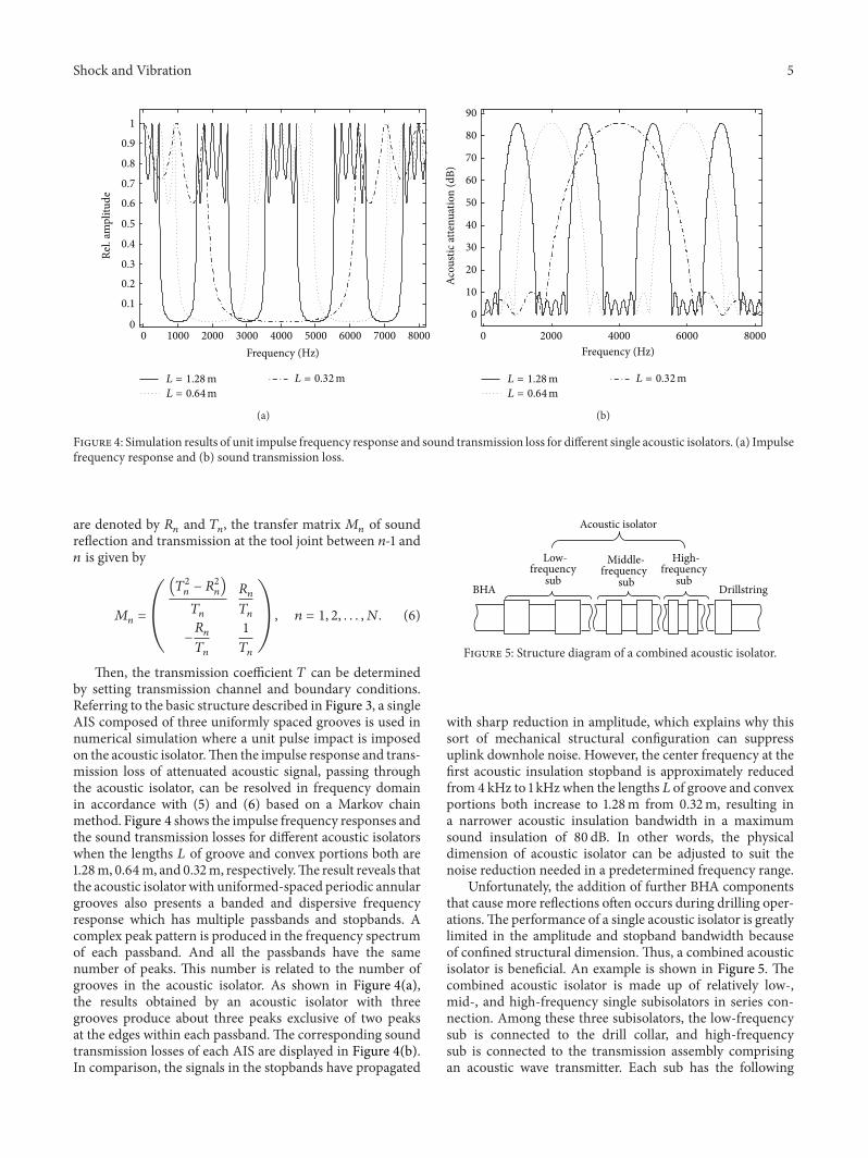
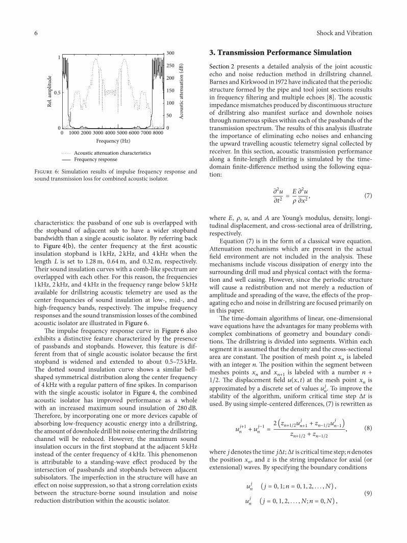
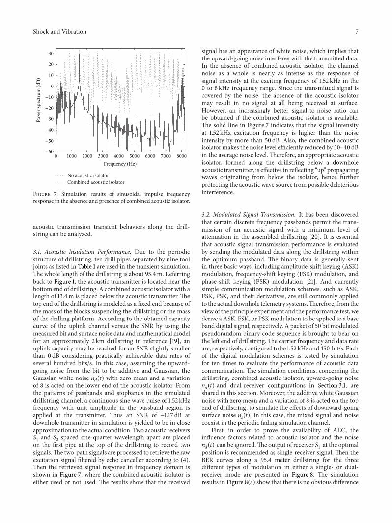

International Journal of
AerospaceEngineeringHindawi Publishing Corporationhttpwwwhindawicom Volume 2014
RoboticsJournal of
Hindawi Publishing Corporationhttpwwwhindawicom Volume 2014
Hindawi Publishing Corporationhttpwwwhindawicom Volume 2014
Active and Passive Electronic Components
Control Scienceand Engineering
Journal of
Hindawi Publishing Corporationhttpwwwhindawicom Volume 2014
International Journal of
RotatingMachinery
Hindawi Publishing Corporationhttpwwwhindawicom Volume 2014
Hindawi Publishing Corporation httpwwwhindawicom
Journal ofEngineeringVolume 2014
Submit your manuscripts athttpwwwhindawicom
VLSI Design
Hindawi Publishing Corporationhttpwwwhindawicom Volume 2014
Hindawi Publishing Corporationhttpwwwhindawicom Volume 2014
Shock and Vibration
Hindawi Publishing Corporationhttpwwwhindawicom Volume 2014
Civil EngineeringAdvances in
Acoustics and VibrationAdvances in
Hindawi Publishing Corporationhttpwwwhindawicom Volume 2014
Hindawi Publishing Corporationhttpwwwhindawicom Volume 2014
Electrical and Computer Engineering
Journal of
Advances inOptoElectronics
Hindawi Publishing Corporation httpwwwhindawicom
Volume 2014
The Scientific World JournalHindawi Publishing Corporation httpwwwhindawicom Volume 2014
SensorsJournal of
Hindawi Publishing Corporationhttpwwwhindawicom Volume 2014
Modelling amp Simulation in EngineeringHindawi Publishing Corporation httpwwwhindawicom Volume 2014
Hindawi Publishing Corporationhttpwwwhindawicom Volume 2014
Chemical EngineeringInternational Journal of Antennas and
Propagation
International Journal of
Hindawi Publishing Corporationhttpwwwhindawicom Volume 2014
Hindawi Publishing Corporationhttpwwwhindawicom Volume 2014
Navigation and Observation
International Journal of
Hindawi Publishing Corporationhttpwwwhindawicom Volume 2014
DistributedSensor Networks
International Journal of