research and development for gas turbine system in gthtr300
TRANSCRIPT

261
Research and Development for Gas Turbine System in
GTHTR300∗
Kazuhiko KUNITOMI∗∗, Shoji KATANISHI∗∗, Shoji TAKADA∗∗,Takakazu TAKIZUKA∗∗, Xing YAN∗∗ and Shinichi KOSUGIYAMA∗∗
The GTHTR300 aiming at electric generation with its thermal efficiency of 46% is asafe and economically competitive HTGR in 2010s. A helium gas turbine system connectedwith the reactor is designed based on existing technologies developed for fossil gas turbinesystems. However, there are some uncertainties in performance of a helium gas compressor,electric magnetic bearings and control system. In order to confirm these technical uncertain-ties, a 1/3 scale model of the compressor and 1/3 scale magnetic bearings will be manufac-tured and tested in the simulated condition of the GTHTR300. Also, a 5 MW helium gas loopcomposed of the gas turbine system and electric heaters will be constructed, and control per-formance during startup and shutdown, and off- normal transients such as loss of off site loadswill be tested to streamline the gas turbine system. This paper describes R&D plans focusingon the 1/3 scale compressor model test as well as unique design features of the GTHTR300.
Key Words: HTGR, HTTR, Gas Turbine, Compressor, Magnetic Bearing, Electric Genera-tion, Safety
1. Introduction
Japan Atomic Energy Research Institute (JAERI)has been developing HTGR technology since the late1960s. The High Temperature Engineering Test Reac-tor (HTTR)(1) was designed constructed and successfullyoperated in Oarai Research Establishment. The heliumgas-cooled, graphite-moderated reactor with its thermalpower of 30 MW and outlet temperature of the maximum950◦C attained the first criticality in November 1998 andthe full power operation with outlet temperature of 850◦Cin December 2001. Experiences obtained from HTTRdesign, construction and operation together with conven-tional fossil gas turbine experiences are applied to the de-velopment of the Gas Turbine High Temperature Reac-tor (GTHTR300) program(2). The GTHTR300 shown inFig. 1 is a safe and economically competitive reactor ex-pected to be deployed in 2 010 s. The GTHTR300 consist-ing of a direct cycle gas turbine system and HTGR withoutlet temperature of 850◦C produces about 300 MWe
∗ Received 30th July, 2003 (No. 03-4183)∗∗ Department of Advanced Nuclear Heat Technology, Oarai
Research Establishment, Japan Atomic Energy ResearchInstitute, Oarai-machi, Ibaraki 311–1394, Japan.E-mail: [email protected]
in a rated operation. The program for designing theGTHTR300 and developing related gas turbine technolo-gies will be carried out in the period of 2001 – 2007.
So far, a reference plant design has been establishedby detailed design iterations made at both component andsystem levels. The GTHTR300 consists of four modu-lar reactor systems with nominal generating capacity of300 MWe per modular unit. The reactor core consists ofthe prismatic pin-in blocks and theses blocks are locatedannularly to enhance the heat removal from the fuel blocksto outside during the loss of coolant accident without re-
Fig. 1 Plant Layout of GTHTR300
JSME International Journal Series B, Vol. 47, No. 2, 2004
262
lying on active safety systems. The low-enriched ura-nium fuel cycle has design characteristics of high burn-up (112 GWd/t), low power peaking factor (< 1.4) foran extended refueling interval(2 years). The long refuel-ing interval increases the reactor availability of more than90% and contributes to low electricity cost of 4 Yen/kWh.The Reactor Pressure Vessel (RPV) cooled in an intrinsicflow scheme makes use of the conventional carbon steel(SA533). That eliminates R&D necessary for the RPVand saves the RPV cost. The system design utilizes thenon-intercooled Brayton cycle because the present studyconcluded that cycle intercooling resulted in substantialcomplexities in turbomachinery and system but providedno compelling advantage in overall plant economy. Thenon-intercooled helium turbomachinery, as compared tothat of intercooled design, exhibits superior aerodynamicefficiency by fewer stages and its rotor is lighter, shorterand more rigid, resulting in more robust vibration charac-teristics. The rotor is laid out horizontally to lower loaddemands on bearings and to take advantage of the exten-sive field experience by industry in handling similar turbo-machine. All turbomachines and heat exchanging compo-nents are sized and arranged in system to ensure effectivemodular construction and independent maintenance. Thisprogram was entrusted from Ministry of Education, Cul-ture, Sports, Science and Technology.
2. Plant Design Discription
2. 1 Utility/User requirementsThe utility/user requirements for GTHTR300 were
established by JAERI in consultation with major domes-tic utilities and industries. All items were determined byconsidering recent circumstances around nuclear develop-ments in Japan. The major requirements from utilities arethe low electricity cost of 4 Yen/kWh that is almost onethird of that of current LWRs. Another specific require-ment is fuel cycle. Fuel recycling policy is enforced inJapan, and the GTHTR300 is compliance with this policy.
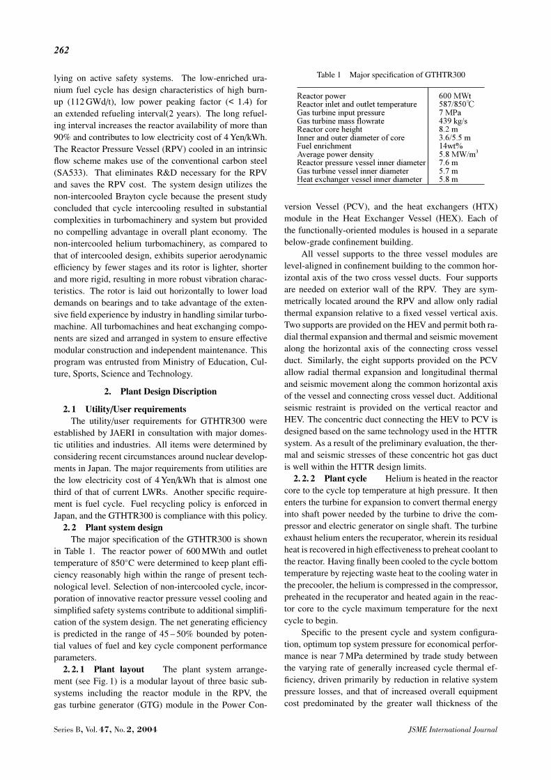
2. 2 Plant system designThe major specification of the GTHTR300 is shown
in Table 1. The reactor power of 600 MWth and outlettemperature of 850◦C were determined to keep plant effi-ciency reasonably high within the range of present tech-nological level. Selection of non-intercooled cycle, incor-poration of innovative reactor pressure vessel cooling andsimplified safety systems contribute to additional simplifi-cation of the system design. The net generating efficiencyis predicted in the range of 45 – 50% bounded by poten-tial values of fuel and key cycle component performanceparameters.
2. 2. 1 Plant layout The plant system arrange-ment (see Fig. 1) is a modular layout of three basic sub-systems including the reactor module in the RPV, thegas turbine generator (GTG) module in the Power Con-
Table 1 Major specification of GTHTR300
version Vessel (PCV), and the heat exchangers (HTX)module in the Heat Exchanger Vessel (HEX). Each ofthe functionally-oriented modules is housed in a separatebelow-grade confinement building.
All vessel supports to the three vessel modules arelevel-aligned in confinement building to the common hor-izontal axis of the two cross vessel ducts. Four supportsare needed on exterior wall of the RPV. They are sym-metrically located around the RPV and allow only radialthermal expansion relative to a fixed vessel vertical axis.Two supports are provided on the HEV and permit both ra-dial thermal expansion and thermal and seismic movementalong the horizontal axis of the connecting cross vesselduct. Similarly, the eight supports provided on the PCVallow radial thermal expansion and longitudinal thermaland seismic movement along the common horizontal axisof the vessel and connecting cross vessel duct. Additionalseismic restraint is provided on the vertical reactor andHEV. The concentric duct connecting the HEV to PCV isdesigned based on the same technology used in the HTTRsystem. As a result of the preliminary evaluation, the ther-mal and seismic stresses of these concentric hot gas ductis well within the HTTR design limits.
2. 2. 2 Plant cycle Helium is heated in the reactorcore to the cycle top temperature at high pressure. It thenenters the turbine for expansion to convert thermal energyinto shaft power needed by the turbine to drive the com-pressor and electric generator on single shaft. The turbineexhaust helium enters the recuperator, wherein its residualheat is recovered in high effectiveness to preheat coolant tothe reactor. Having finally been cooled to the cycle bottomtemperature by rejecting waste heat to the cooling water inthe precooler, the helium is compressed in the compressor,preheated in the recuperator and heated again in the reac-tor core to the cycle maximum temperature for the nextcycle to begin.
Specific to the present cycle and system configura-tion, optimum top system pressure for economical perfor-mance is near 7 MPa determined by trade study betweenthe varying rate of generally increased cycle thermal ef-ficiency, driven primarily by reduction in relative systempressure losses, and that of increased overall equipmentcost predominated by the greater wall thickness of the
Series B, Vol. 47, No. 2, 2004 JSME International Journal

263
pressure vessels, all with respect to increase in systempressure.
GTHTR300 employs the simplest or non-intercooledBrayton cycle (see Fig. 2). Cycle intercooling was ruledout, even though it achieves up to two percent higher ther-mal efficiency, because the gain in efficiency is not suf-ficient to override the associated cost increment of addedsystem complexities. The latter include substantially moreturbine and compressor stages due to increase in optimumcycle pressure ratio from 2.0 for non-intercooled cycle to2.4 for intercooled cycle, at least one more each of com-pressor sector and intercooler, and an expanded primarysystem boundary to accommodate the additional compo-nents. In absence of a compelling economical advantageoffered by cycle intercooling, the non-intercooled cycle isstrongly preferred for maximum design simplicity.
Core outlet coolant temperature, being equal to tur-bine inlet temperature, is one of the most sensitive cy-cle parameters affecting cycle thermal efficiency. Withall other cycle parameters unchanged, cycle efficiency in-creases by 1.5% for each increment of 50◦C in core out-let temperature. The effect remains great even if associ-ated design changes such as additional turbine blade cool-ing due to high blade temperature beyond metallurgy limitare taken into account. Therefore, the highest core outlettemperature allowed by fuel should be selected. Judgedfrom available fuel performance database, the present fuelbased on SiC coated particles is capable of core outletcoolant temperature in the range of 850 – 950◦C.
Once core outlet temperature is fixed, core inletcoolant temperature is determined by the choice of cy-cle pressure ratio. When the RPV is cooled by core inletcoolant flow as it was typically done, core inlet tempera-ture must be limited to the acceptable range of availablevessel steels. This can only be satisfied by setting cyclepressure ratio significantly higher than the optimum valuefor efficiency. The present design employs a different RPVcooling scheme that, as to be detailed in a later section, isnot dependent on core inlet coolant flow. As a result, the
Fig. 2 Heat mass balance of the GTHTR300
core inlet temperature is set simply by choosing the cyclepressure ratio for peak cycle efficiency.
The optimum cycle pressure ratio for peak efficiencyoccurs at a narrow range of 2.0 – 2.2 in the GTHTR300non-intercooled cycle with the lower bound being selectedby the design. The low value of the optimum cycle pres-sure ratio benefits the turbomachine design by minimizingthe number of stages required in turbine and compressorand by making large volume flow available to augment-ing aerodynamic efficiency. The adverse effect of the lowpressure ratio is large thermal load necessarily in recuper-ator. This is easily accommodated, with overall systemcost saving, by the extraordinary specific thermal capac-ity, 30 MW/m3, of the compact recuperator design, whichis described later.
2. 2. 3 Plant performance The performancecharacteristics of the GTHTR300 non-intercooled cy-cle (see Fig. 3) indicate that the potential of net plantefficiency is in the range of 45 – 50% bounded by aminimally-expected and a targeted set of significantperformance parameters of the fuel and key cyclecomponents. Only details of the plant design andperformance data based on the more conservative orminimally-expected performance parameters are givenhere (Table 2). In this case, the plant yields 45.6%net generation efficiency. The efficient performance isattributed to a number of important performance featuresof the present cycle design including selection of cyclepressure ratio for peak efficiency, low cycle pressurelosses, and high performance turbomachine.
The efficiency of up to 50% is attainable without anysignificant change to be made in component or systemphysical design. This valuable design property is depictedin Fig. 3 where the optimum pressure ratio for cycle ef-ficiency remains practically unchanged from the baselinecycle having 850◦C core outlet temperature or turbine in-let temperature (TIT) and 0.95 recuperator effectiveness tothe advanced cycle having 950◦C TIT and 0.96 recupera-
Fig. 3 GTHTR300 non-intercooled Brayton cycle performancecharacteristics and projected efficiency range
JSME International Journal Series B, Vol. 47, No. 2, 2004

264
Table 2 Comparison of major specifications of model andGTHTR300 compressor
tor effectiveness. This is due to the fact that the optimumcycle pressure ratio for efficiency increases with increas-ing TIT but reduces with higher recuperator effectiveness,both weighing similar but opposite effect. The constantcycle pressure ratio retains the basic cycle thermodynamicconditions such as temperature variant and flow velocityin core and turbomachine. This avoids any major designchange in the key components and system as the plant ap-proaches to the advanced cycle performance regime.
3. R&D for Gas Turbine System
3. 1 Compressor performance testThe helium gas compressor in the GTHTR300 is axial
flow multi-stage compressor. The number of stages is 20and the pressure ratio is 2.0. The cross sectional view ofthe compressor is shown in Fig. 4. The design resulted inpolytropic efficiency of 90% and surge margin of 30% atdesign point, in case when the tip clearance is set at 1 mm.
A 1/3 scale model compressor consisting of four axialstages is manufactured to carry out aero performance testsin a helium loop. It is aimed at evaluating the specificaerodynamic features of the flow path design used in thefull-scale GTHTR300 compressor. The key performanceconsiderations include predicated compressor surge mar-gin, aerodynamic losses near the end wall in the multiplerotating blade rows as well as inlet and outlet performance,all to be correlated to closely simulated helium workingconditions.
The stages from the first to forth of the test modelare geometrically similar to the corresponding stages ofthe GTHTR300 compressor. Tip clearance was also mod-eled with geometric similarity. The blade can be machinedwith the tolerances less than 0.1 and 0.15 (mm) for theouter blade diameter and the blade profile, respectively.The Reynolds number in the model and the GTHTR300compressors (= blade chord length × peripheral speed /dynamic viscosity) is 7.55× 10⁵ under the nominal testcondition and 9.03×10⁶ under the rated operational con-dition, respectively. The Reynolds number of the 1/3 scale
Fig. 4 Helium gas compressor of GTHTR300
Fig. 5 Cross sectional view of the model compressor
model is sufficiently large compared to the lower limit of2×105 below which a blade loss rapidly increases. The pe-ripheral speed in the model is kept the same as that of theGTHTR300 compressor although the helium gas pressureis less than 1.0 MPa. In the tests, inlet pressure will be var-ied from 0.88 MPa to 0.2 MPa to investigate the effects ofthe Reynolds number on the aerodynamic performance ofthe model. Table 2 shows comparison of the major spec-ification between the compressor in GTHTR300 and 1/3scale model. Figure 5 shows the cross sectional view ofthe compressor model.
In the model tests, dynamic pressures, gas pressuresflowrate and so on are measured. A traversing sensorinstalled in a flow path is used to measure the dynamicpressure profile. For the gas temperature measurements,thermo-couples placed at several positions in the flow patsare used.
The main shaft of the compressor model is supportedby oil lubricant journal bearings mounted on both ends ofthe shaft, and a thrust bearing mounted on the shaft endopposite to the motor side. In order to prevent helium gasleakage though the shaft and casing, dry gas seals (DGS)are placed at the shaft penetration sections. The DGS con-sisting of a rotating plate and stator plate around the shaftruns well in a high-speed condition. A suction and dis-charge casing are designed to keep the pressure loss in thecasing as low as possible. The casing consists of three
Series B, Vol. 47, No. 2, 2004 JSME International Journal

265
parts (suction, intermediate and discharge). Pipes with aninner diameter of 492.2 (mm) is connected to the casingsfor suction and discharge.
The model compressor and an overall layout of thehelium gas test loop is shown in Fig. 6. Figure 7 showsthe schematic drawing of the test loop. The test loop con-sists of the compressor model, cooler, pressure adjustmentvalve and flow rate measurement pipes. The shaft of themodel is driven by an electric motor via a step-up gear.The rated rotational speed of the motor is 1 800 rpm andthe step-up ratio is 6, turning the compressor model at10 800 rpm.
The helium gas pressure at the inlet and outlet of thecompressor model is controlled by the pressure adjustmentvalve, and the helium gas temperature is controlled by thecooler (helium gas/water heat exchanger).
The inner diameter of the flow rate measurement pipe
Fig. 6 Model compressor and test loop
Fig. 7 Schematic drawing of the test loop
is 590.6 mm. Helium gas flow rate is measured by an ori-fice type flow meter.
3. 2 Magnetic bearing developmentAn existing bearing with lubricants such as water and
oil cannot be available in the HTGR system because thewater or oil ingress causes severe damage in the core. Fourradial magnetic bearings and one thrust magnetic bearingare used to suspend rotors for the turbocompressor andgenerator (see Fig. 4). The rotor weight is 46 t for theturbocompressor and 67 t for the generator, respectively.These rotors shall be operated stably when they pass overthe first and the second critical speeds of bending mode,and the vibration shall be within the limit of 75 µm in anynormal operation condition. A flexible coupling placedbetween these rotors isolates vibration of the two rotorsworks to avoid instability effects such as the spill over ofthe higher vibration modes and the non-collocation of theelectro-magnet and sensors.
The maximum weight of an existing rigid rotor sus-pended by the magnetic bearing is 35 t. The loading ca-pacity is close to those of the GTHTR300. However, itoperates at a relatively low rotational speed of 600 rpm(3)
below any critical speed of bending vibration mode. Onthe other hand, the maximum weight of an existing flexiblerotor which is suspended by 3 magnetic bearings is 9.3 t,which passes over a critical speed of the second bendingmode below the rated rotational speed at 5 800 rpm(4). Theloading capacity of this magnetic bearing is rather smallcomparing with those of the GTHTR300, and the controlscheme of the magnetic bearing cannot be directly appli-cable.
In the GTHTR300 system, the rated rotor speed of3 600 rpm is higher than the critical speed of the first andsecond bending mode. Figures 8 and 9 show the rela-tionship between the critical speed of each bending modeand the bearing stiffness calculated based on the numericalmodels shown in Figs. 10 and 11. Since the magnetic bear-ing stiffness is designed to be 1.0×10⁹ N/m, these rotors
Fig. 8 Relationship between bearing stiffness and critical speedfor the turbocompressor rotor
JSME International Journal Series B, Vol. 47, No. 2, 2004

266
Fig. 9 Relationship between bearing stiffness and critical speedfor the generator
Fig. 10 Turbinecompressor model
Fig. 11 Generator rotor model
pass over the critical speed of the first and second bend-ing mode before reaching the rated speed. The rotors shallbe stable when they pass the critical speed. The develop-ment of the control scheme of these large-scale magneticbearings is necessary.
The development is focused on evaluation of ap-
propriate control scheme of the magnetic bearings fora 1/3 scale single-shaft rotor system modeled after theGTHTR300 turbomachine rotating assembly. Existing an-alytical techniques of finite element method will be cali-brated in tests to include the on-demand controllability ofthe magnetic bearing stiffness and damping parameters,unavailable to conventional bearings, to alter or optimizethe rotor transient responses to critical speeds.
A catcher bearing is also key component to develop.It supports the large scale rotor of the compressor, turbineand generator during a loss of electricity accident. The ex-isting ball bearing cannot be available for this large scalesystem. In this development, several type of catcher bear-ings will be designed and one of them will be selected andtested for confirming its performance and integrity.
3. 3 Operational control testThe small-scale (less than 1/3 scale and thermal
power of lower than 5 MW) helium closed cycle turbinesystem will be constructed and operated to demonstrateappropriate control algorithms and apparatuses and to ver-ify system dynamic simulation codes to be used for designand operations validation of the GTHTR300. The reactorpower control adjusting electricity demand at day time andnight is necessary for the cost saving of the system. TheGTHTR300 can control the power from 30% to 100%.
4. Conclusions
The GTHTR300 is expected to be a new energysource in 2 010 s due to salient combination of highly ef-ficient electric gas turbine and HTGR system. In orderto achieve early deployment, most of the components inthis system are designed based on current technologies.Several R&Ds were planned to solve the only remaininguncertainty of performance in key components such as thehelium gas compressor, magnetic bearing and so on.
The 1/3 scale model compressor was designed andmanufactured to confirm technological uncertainty of thecompressor. The test condition and size of the model wasproperly designed. The aero dynamic test for the com-pressor will be conducted by the end of FY-2004. The testresults will be reflected on the design of the GTHTR300compressor.
The magnetic bearing test and control operationaltests are also planed. The detailed design is under wayand their manufacturing will start in 2004.
Acknowledgements
Authors would like to thank Messers H. Itaka, E.Mori, M. Tanihira and I. Minatsuki in Mitsubishi HeavyIndustries LTD., for their kind assistance.
References
( 1 ) Saito, S., et al., Design of High Temperature Engineer-ing Test Reactor (HTTR), JAERI 1332 (1994).
Series B, Vol. 47, No. 2, 2004 JSME International Journal

267
( 2 ) Kunitomi, K., et al., Design Study on Gas Turbine HighTemperature Reactor (GTHTR300), Proc. of SMIRT16, Washington DC, USA, (2001).
( 3 ) S2M, Actidyne News, Vol.8, No.3 (1998).( 4 ) Kuemmlee, H., Groot, W., Lenderink, G., et al., De-
sign and Experience with a 30 000HP Magnetic Bear-ing Supported Motor Driven Turbo-Compressor for aSpeed Range of 600 to 6 300 rpm, Proceedings of the29 th Turbomachinery Symposium, Texas A&T Uni-versity, (2000).
JSME International Journal Series B, Vol. 47, No. 2, 2004