research paper · 2016-02-29 · ocp presents an efficient solution to address soc contemporary...
TRANSCRIPT


286
This article can be downloaded from http://www.ijerst.com/currentissue.php
Int. J. Engg. Res. & Sci. & Tech. 2015 Yalavarthi Ramakrishna Paramahamsa, 2015
AN SOC IMPLEMENTATION OF HIGH SPEED OCPSWITCH ARCHITECTURE
OCP presents an efficient solution to address SoC contemporary design issues and shortertime-to-market requirements using an industry standard socket. The on chip permutation followsthe industrial OCP protocol. The design which complies with the bus interface protocol to carryout the various advanced bus functionality consequently dominates the communication efficiencyof an SOC system. OCP is flexible and configurable to support the communication needs of awide range of Intellectual Property cores, and is now in widespread use. Various bus transactionsdefined in AXI and OCP to reduce the communication latency and increase the bus throughputare supported by the proposed bus architecture. The Functional-simulation has been successfullycarried out with the results matching with expected ones which shows the effective solution forthe communication field. The design functional verification and Synthesis is done by using Xilinx-ISE.
Keywords: System-On-chip, OCP, Xilinx-ISE, Verilog
INTRODUCTIONCurrent technology trends, scaling, and with endusers showing a marked preference for thesmaller geometries of deep submicronprocesses forces a design style where multipleindependent circuit implementations areintegrated together into single System-on-Chip(SoC). However, contemporary SoC designshave their own share of issues and challenges.The major challenges faced by a design engineerinclude the ever increasing complexity in modern
1 Professor, Brindavan Institute of Technology and Science (BITS), Kurnool 518218, AP, India.
Int. J. Engg. Res. & Sci. & Tech. 2015
ISSN 2319-5991 www.ijerst.comVol. 4, No. 2, May 2015
© 2015 IJERST. All Rights Reserved
Research Paper
SoC designs, reusability, time to-market,communication between Intellectual Property (IP)cores, integration of different clocked domain IPcores, and global clock distributions on a chip..As an organization, OCP-IP guides thedevelopment of the industry standard by providingthe specification, as well as EDA tools and models,to further ease the task of SoC development.OCP research is mainly targeted to provide aneff icient solution to address SoC designchallenges by building standard NoC interfaces
Yalavarthi Ramakrishna Paramahamsa1*
*Corresponding Author: Yalavarthi Ramakrishna Paramahamsa [email protected]

287
This article can be downloaded from http://www.ijerst.com/currentissue.php
Int. J. Engg. Res. & Sci. & Tech. 2015 Yalavarthi Ramakrishna Paramahamsa, 2015
using an industry standard socket interface, OpenCore Protocol (OCP).
OCP SYSTEMIn an OCP system, communicating components(e.g., processors, memory modules, and I/Odevices) need a wrapper which implements theOpen Core Protocol interface. This interfaceenforces a point-to-point unidirectionalcommunication when two components arecommunicating, the one that utilizes a “master”OCP port sends to the other that utilizes a “slave”OCP port. Communication protocols deal withdif ferent types of resource managementalgorithms used for determining access right toshared communication channels. From this pointof view, in the rest of this section, we will give abrief comment related to the main feature of theexisting communication protocols. OCP is mainlytargeted to provide an efficient solution to addressSoC design challenges by building standard NoCinterfaces using an industry standard socketinterface, Open Core Protocol (OCP). Also thereare few motivating factors from an industrialperspective internalization and implementation ofthis project. Levels of device integration leads toSoC design style SoC provides the platform forintegration of different architectural cores suchas microprocessor chips, Application SpecificIntegrated Circuit (ASIC) chips, Random AccessMemory (RAM) chips, and peripherals on a singledie.
The major advantage of SoC design overcustom design is its shorter time-to-market, butat the expense of performance and area. SoCdesigns help enable IP reusability when theyutilize a standard communication interface.Employing a standard socket interface on a SoCenables reuse of the good design swith minimal
modification to IPcores. This project targets theshorter time-to-market feature of SoCs to buildstandard interfaces between IPcores at theexpense of power, performance, and area. SoCdesign Scan Sea NoCoron-chip bus as the on-chip communication medium between IP cores.Network-on-chip is an efficient communicationmedium compared to bus because of itsadvantages like the following:
1. Efficiency improvement in speed, bandwidth,area, and power consumption.
2. Supports concurrency-effective spatial reuseof resources.
3. Low latency.
4. Scalable bandwidth
5. Modularity.
The Open Core Protocol (OCP) is a corecentric protocol which defines a high-performance, bus-freelance interface between IPcores that reduces design time, style risk, andproducing costs for SOC styles. Main property ofOCP is that it can be configured with respect tothe application needed.
Evaluation and Comparison with OtherBusesAn SOC chip usually contains a large numberof IP cores that communicate with each otherthrough on-chip buses. As the VLSI processtechnology continuously advances, thefrequency and the amount of the datacommunication between IP cores increasesubstantially. As a result, the ability of on chipbuses to deal with the large amount of data trafficbecomes a dominant factor for the overallperformance. The design of on-chip buses canbe divided into two parts: bus interface and busarchitecture. The bus interface involves a set of

288
This article can be downloaded from http://www.ijerst.com/currentissue.php
Int. J. Engg. Res. & Sci. & Tech. 2015 Yalavarthi Ramakrishna Paramahamsa, 2015
interface signals and their corresponding timingrelationship, while the bus architecture refers tothe internal components of buses and the inter-connections among the IP cores. The OpenCore Protocol (OCP) is an open standard, bus-independent protocol provided by Open CoreProtocol-International Partnership (OCP-IP). Itmeets all the core centric requirements and isone of the protocols which unifies all the intercore communications including sideband controland test signals. OCP def ines a highperformance, complete interface socketbetween IP cores facilitating design reuse, andalso reduces design time, design risk, andmanufacturing costs for SoC designs. OCPsupports very high-performance data transfermodels ranging from simple request-grantsthrough burst pipelined and tagging objects.OCP protocol compliance verification is one ofthe distinguishing features from other protocols.OCP-IP not only provides the specification andits member-driven evolution, but also industrialgrade tools and services that ensure itsmembers can rapidly confirm compliance andmaximize their productivity.B. Overview of theAMBA
The AMBA AHB which is mainly a shared buscomposed of multiplexors; it can be permitted toa design with small number of IP Cores. Whenthe IP Cores increases then the overallperformance can be reduced. In order to improvethe communication efficiency among the largeno of IP Cores two more Protocols have beenproposed. One is Advanced extensible Interfaceprotocol (AXI) proposed by the ARM company.The Advanced Microcontroller Bus Architecture(AMBA) specification defines an on-chipcommunications standard for designing high-performance embedded microcontrollers. Three
distinct buses are defined within the AMBAspecification:
1. The Advanced High-performance Bus (AHB)
2. The Advanced System Bus (ASB).
3. The Advanced Peripheral Bus (APB).
A Test methodology is included with the AMBAspecification which provides an infrastructure formodular macro cell test and diagnostic access.
OCP DescriptionCommonly an OCP transfer is made of twoseparate and temporally decoupled phases, onefor the request, and one for the response.Progression within a phase is controlled by atwo-way handshake between thecommunicating entities. A phase begins with oneside asserting the signals associated with thatphase. The OCP commands are generallyaccompanied by an address field. In a standardsystem, it is the responsibility of the chipinterconnection network to route the request tothe appropriate target, based on this address.As an illustration of the OCP flexibility, it isinteresting to point out here that it is perfectlylegal for a local OCP interface not to include anyaddress information. More generally, an OCPinterface is defined with a very comprehensiveset of parameters, which allows enabling/disabling most of the signals individually. As aconsequence, commonly-used interface modelssuch as read-only, write-only, synchronization-only or FIFO interfaces can be easily described.The OCP interface parameters are defined in aset of configuration files, shared by the differenttools in the development environment as a fullyexecutable specification.
The Open Core Protocol is an openlylicensed, core-centric protocol standard, which

289
This article can be downloaded from http://www.ijerst.com/currentissue.php
Int. J. Engg. Res. & Sci. & Tech. 2015 Yalavarthi Ramakrishna Paramahamsa, 2015
defines a high performance, synchronous, busindependent conf igurable inter face forcommunication between IP cores and NoC. Itis an eff icient point-to-point connectionstandard and because of its configurability,scalability, and generality, it has been widelyaccepted from low-power to high-performanceapplications. It can be optimized to use onlythe necessary features required forcommunicating between any two components,which saves chip area. It dramatically improvesreusability of IP cores independent of thearchitecture and design of the systems, whichleads directly to a more predictable, productiveSoC designs and also simplifies the systemverification and testing. OCP consists of anaggregation of signals that aims to unify thecommunication among IP blocks, reducing thesystem design time significantly. It is comprisedof a continuum of communication protocolsthat share common definition for the wholesystem where it ensures dramatic t imereduction-of functional verification for any futurereleases of the system.
DESIGN DESCRIPTIONOCP is one of the viable core-centric solutionsto address contemporary SoC designimplementation requirements. Commerciallyexisting native OCP interfaces (integrated into IPCores) are fully synchronous in nature which limitsan IP core’s capabilities to interface with otherclocking control methodologies. In order to exploreother clocking control methods, this researchstudy designs and builds modular clockedwrapper OCP interfaces (OCP located outsidethe IP core) for existing IP cores. The Open CoreProtocol is an openly licensed, core-centricprotocol standard, which defines a high
performance, synchronous, bus independentconfigurable interface for communicationbetween IP cores and NoC. It is an efficient point-to-point connection standard and because of itsconfigurability, scalability, and generality, it hasbeen widely accepted from low-power to high-performance applications. It can be optimized touse only the necessary features required forcommunicating between any two components,which saves chip area. It dramatically improvesreusability of IP cores independent of thearchitecture and design of the systems, whichleads directly to a more predictable, productiveSoC designs and also simplifies the systemverification and testing. OCP consists of anaggregation of signals that aims to unify thecommunication among IP blocks, reducing thesystem design time significantly. It is comprisedof a continuum of communication protocols thatshare common definition for the whole systemwhere it ensures dramatic time reduction -offunctional verification for any future releases ofthe system.
This research develops a new approach toincrease modularity, improve reliability, andreduced sign time to interface different IPs to theOCP socket. This consists of splitting the designinto common shared components and customback-ends that are specific to the IP core. Thecommon components consist of OCP masterand slave components and a Domain Interface(DI) module. The DI module is used tosynchronize mutually asynchronous clockeddomains and data flow control. These will bedescribed in more detail in this chapter.
Design Specifications and SupportingFeaturesThe OCP methodology presented enables
290
This article can be downloaded from http://www.ijerst.com/currentissue.php
Int. J. Engg. Res. & Sci. & Tech. 2015 Yalavarthi Ramakrishna Paramahamsa, 2015
response to the original request which triggeredit. By supporting out-of-order responses, in mostcases, the use of tags can improve overallsystem performance since responses are nothalted due to dependencies on previoustransactions. In this project implementation, atag size of 8 is employed.In this work, thenumerous OCP profiles will be designed usingVerilog and the developed design will be usedwith respect to its appropriate application in theimportant time product. Basically the OCPunifies all inter-core communications. TheOCP’s synchronous unidirectional signalingproduces simplif ied core implementation,integration and timing analysis. The OCP readilyadapts to support new core capabilities whilelimiting check suite modifications for coreupgrades.
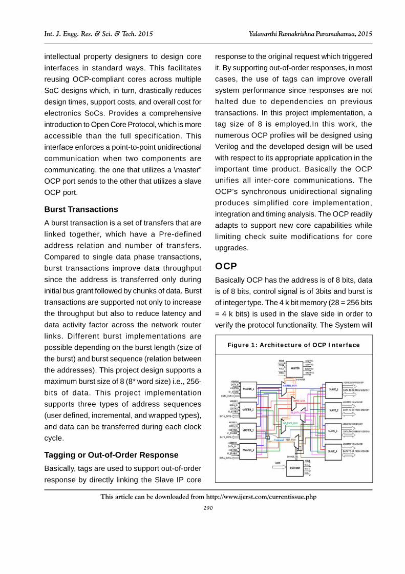
OCPBasically OCP has the address is of 8 bits, datais of 8 bits, control signal is of 3bits and burst isof integer type. The 4 k bit memory (28 = 256 bits= 4 k bits) is used in the slave side in order toverify the protocol functionality. The System will
intellectual property designers to design coreinterfaces in standard ways. This facilitatesreusing OCP-compliant cores across multipleSoC designs which, in turn, drastically reducesdesign times, support costs, and overall cost forelectronics SoCs. Provides a comprehensiveintroduction to Open Core Protocol, which is moreaccessible than the full specification. Thisinterface enforces a point-to-point unidirectionalcommunication when two components arecommunicating, the one that utilizes a \master”OCP port sends to the other that utilizes a slaveOCP port.
Burst TransactionsA burst transaction is a set of transfers that arelinked together, which have a Pre-definedaddress relation and number of transfers.Compared to single data phase transactions,burst transactions improve data throughputsince the address is transferred only duringinitial bus grant followed by chunks of data. Bursttransactions are supported not only to increasethe throughput but also to reduce latency anddata activity factor across the network routerlinks. Different burst implementations arepossible depending on the burst length (size ofthe burst) and burst sequence (relation betweenthe addresses). This project design supports amaximum burst size of 8 (8* word size) i.e., 256-bits of data. This project implementationsupports three types of address sequences(user defined, incremental, and wrapped types),and data can be transferred during each clockcycle.
Tagging or Out-of-Order ResponseBasically, tags are used to support out-of-orderresponse by directly linking the Slave IP core
Figure 1: Architecture of OCP Interface

291
This article can be downloaded from http://www.ijerst.com/currentissue.php
Int. J. Engg. Res. & Sci. & Tech. 2015 Yalavarthi Ramakrishna Paramahamsa, 2015
give the inputs to OCP Master during Writeoperation and receive signals from OCP Slaveduring Read operation.
OCP SpecificationThe specifications for the Open Core Protocolare identified for both simple write and readoperation supports the pipelining operation andburst operation. The identified specificationsare represented in tabulation format. The OpenCore Protocol inter face addressescommunications between the functional units(or IP cores) that comprise a system on a chip.The OCP provides independence from busprotocols without having to sacrifice high-performance access to on-chip interconnects.By designing to the interface boundary definedby the OCP, you can develop reusable IP coreswithout regard for the ultimate target system.To simplify timing analysis, physical design, andgeneral comprehension, the OCP is composedof uni-directional signals driven with respect to,and sampled by the rising edge of the OCPclock. The OCP is fully synchronous andcontains no multi-cycle timing paths. All signalsother than the clock are strictly point-to-point.The OCP separates requests fromresponses. A slave can accept a commandrequest from a master on one cycle andrespond in a later cycle. The division of requestfrom response permits pipelining. The OCPprovides the option of having responses forWrite commands, or complet ing themimmediately without an explicit response.
Simple Write and ReadThis simple write and read operation for whichthe basic and mandatory signals required signalsare tabulated in Table 5.1. The Open CoreProtocol (OCP) defines a high-performance, bus-independent interface between IP cores. OCP
defines a point-to-point interface between twocommunicating entities. One entity acts as themaster of the OCP instance, and the other asthe slave. Only the master can presentcommands and is the controlling entity. The slaveresponds to commands presented to it, either byaccepting data from the master, or presentingdata to the master. The OCP defines completestandard from the basic data flow signals to thesignals that are used for test purposes. Broadly,OCP signals can be divided into two maincategories, the basic OCP signals and theoptional OCP signals. The presence of basicOCP signals in any core is necessary if it isfollowing the OCP interface. The optional OCPsignals can be included according to therequirement. The OCP transforms IP coresmaking them independent of the architecture anddesign of the systems in which they are used.Optimizes die area by configuring into the OCPonly those features needed by the communicatingcores.An IP core can be a simple peripheral core,a high-performance microprocessor, or an on-chip communication subsystem such as awrapped on-chip bus.
OCP ArbiterArbiter inputs are the request signals from the allfour master’s which are MReq1, MReq2, MReq3and MReq4. Arbiter will issue the MGarantx1,MGarantx2, MGarantx3 and MGarantx4 to any oneof the master’s. Whichever the master sentMReq signal that master will get the MGrantxsignal. Arbiter gives MMaster signal to the Addressmux, Burst mux and Write Data mux as aselection signal.
OCP MasterOCP master have Clk, Enable Clk as inputs.And also the master gets the addr,data_in,control, size signal as input and gives

292
This article can be downloaded from http://www.ijerst.com/currentissue.php
Int. J. Engg. Res. & Sci. & Tech. 2015 Yalavarthi Ramakrishna Paramahamsa, 2015
MAddr, Mdata, MWrite, and Mburst as outputs.MReq signal is output goes to the arbiter andgets MGrantx as input. Other inputs areSCmd_accept, SData, and SResp from theslave. When master is write operation data onthe data_in signal port will transfer to the MDataand when master is write operation data on theSData signal port will transfer to the data-outsignal. And master also gives the MTrans signalwhich specifies data transfer in to or from thememory write or read in SEQ or NON_SEQ.MSize signal for no bits in each transfer hereMSize width is 8-bit.
OCP SlaveThe below figure shows the MAddr, Mdata,MWrite, Mburst. MTrans, MSize and SSelx signalas inputs and SCmd_accept, SData,SResp asoutputs. Whenever slave makes write or readoperation SCmd_accept signal will be high to Lowand Low to High logic level. SResp, signal isacknowledgement signals to the master thatslave has performed read or write operation.
Figure 2: OCP Arbiter
Figure 3: OCP Master
Figure 4: OCP Slave
Write and Read OperationThe simple write and read operation in OCP hasthe mandatory signals whose specification ismentioned in the Table 1.
Control Command
000 Idle
001 Simple Write
010 Simple Read
Table 1: OCP Operation
FSM for OCP MasterThe Finite State Machine (FSM) is developed forthe simple write and read operation of OCPMaster. The simple write and read operationindicates that the control goes to IDLE state afterevery operation. The FSM for the OCP Master –

293
This article can be downloaded from http://www.ijerst.com/currentissue.php
Int. J. Engg. Res. & Sci. & Tech. 2015 Yalavarthi Ramakrishna Paramahamsa, 2015
Simple Write and Read is developed and isshown in the Figure 6.1. Totally there are fourstates are available in this FSM such as IDLE,WRITE, READ and WAIT. Basically, the operationin the OCP will be held in two phases.
1. Request Phase
2. Response Phase
Initially the control will be in IDLE state (Control= “000”) at which all the outputs such as MCmd,MAddr and MData are set to “don’t care”. Thesystem will issue the request to the master suchwrite request which leads to the WRITE state(Control = “001”). In this state, the address andthe data will be given to the slave that is to bewritten and hence the process will get over onlywhen the SCmd_Accept is asserted to high.
If SCmd_Accept is not set, this represents thatthe write operation still in process and the controlwill be in the WRITE state itself. Once the writeoperation is over the control will go to the IDLEstate and then it will check for the next request.
in turn provides the grant signal. Hence based onthe control and the grant signal, OCP Mastereither goes to WRITE or READ state. If controlfrom the system is a write request (Control =“001”), then the OCP Master go WRITE state andwill issue the address (MADDR) and input data(MDATA) to the slave and also makes theMWRITE signal to high. Once these signals areissued, it will wait for the SCMD ACCEPT signalwhich will come from the slave after finishing theoperation. Once the SCMD ACCEPT signaloccurred, then the OCP Master will go to the IDLEstate again. Similarly, when system gives readrequest (Control = “010”), master goes to theREAD state and will give address (MADDR) andmake MWRITE signal to Low. The data in thegiven address will be read out by the data outsignal. Master go IDLE state when the SCMDACCEPT signal is made high which representsthe operation got over.
FSM for OCP SlaveThe FSM for the OCP Slave which has the simplewrite and read operation is developed and isshown in the Figure 6.Figure 5: FSM for OCP Master-Simple Write
and Read
The Finite State Machine (FSM) for the OCPmaster simple write and read operation isdeveloped and is shown in the Figure 5. OCPMaster will be in IDLE State at the initial stageand will give the request signal to the arbiter which
Figure 6: FSM for OCP Slave-Simple Writeand Read
The slave will be set to the respective statebased on the MCmd issued by the master andthe output of this slave is that the SCmd_Accept

294
This article can be downloaded from http://www.ijerst.com/currentissue.php
Int. J. Engg. Res. & Sci. & Tech. 2015 Yalavarthi Ramakrishna Paramahamsa, 2015
and SResp. Initially control will be in the IDLE stateand when the master issues the command aswrite request, and then the control will go theWRITE state in which the data will be written tothe corresponding memory address locationwhich is sent by the masters. Once the writeoperation is finished, the SCmd_Accept signal isset to high and is given to the master.When MCmdis given as read request, then the control willmove to the READ state in which the data willread from the particular memory address locationthat is given by the master. Hence theSCmd_Accept is set to high and the SResp isset to the DVA which represents that the readoperation over and control goes to the IDLE state.
RESULTSResults for the OCP interface had taken for allmodules individually and test cases are passed
through testbench, written in Verilog 2001 and theresults for module are described as follows:
Figure 7: Schematic View of the Top Module
Figure 8: RTL Schematic View of the Top Module
Figure 9: Wave Form of the Top Module
Device Utilization Summary (Estimated Values)
Logic Utilization Used Available Utilization
Number of Slices 81 4656 1%
Number of Slice Flip Flops 44 9312 0%
Number of 4 input LUTs 152 9312 1%
Number of bonded IOBs 44 232 18%
Number of GCLKs 1 24 4%
Table 2: Design Summary
From the waveform it is clearly demonstratethat data in signal sends the user transmitted datato the corresponding multiprocessors accordingto the address being given through the enablesignal. The RTL Schematic describes the userview of the system through which the flow of thesignal will be easily understood. The designsummary report describes the utilization factoramong the available resources. Based on thenumber of 4 input LUTs the area utilization shouldbe calculated.
CONCLUSIONThis project can be extendable between morethan two IP-cores interacting simultaneouslyusing arbiter and Mutual exclusion elements. Thecurrent trend of the bus standard is to define anexplicit bus interface and leave the internal bus

295
This article can be downloaded from http://www.ijerst.com/currentissue.php
Int. J. Engg. Res. & Sci. & Tech. 2015 Yalavarthi Ramakrishna Paramahamsa, 2015
architecture to the bus interface and leave theinternal bus architecture to the bus designer. Thedesign which compiles with the bus interfaceprotocol to carry out the various advanced busfunctionality consequently dominates thecommunication efficiency of an SOC system. Inthis paper it is clearly shown the functionality ofthe On-Chip Permutation Network forMultiprocessor System-On-Chip which should beverified by XILINX ISE simulator.This project hasbeen implemented by considering bursting dataflow features of OCP. The other features of OCP,such as sideband and test signals, can besupported as extensions to this project. burstingsizes, as well as address and data widths, canalso be increased to support higher data flowrequirements.
REFERENCES1. Advanced Microcontroller Bus Architecture
(AMBA) Specification Rev 2.0 & 3.0, http://www.arm.com
2. AMBA AHB Specification
3. AMBA AXI Protocol Specification
4. ARM, AMBA Overview
5. Corp S (2002), “Wishbone System-on-Chip(SoC) Interconnection Architecture forPortable IP Cores”, http://www.silicore.net/pd les/wishbone.pdf
6. OCP3.0 Specification (www.ocpip.org).
7. OCP-IP, “Socket-Centric IP Core InterfaceMaximizes IP Applications”, http://www.ocpip.org/white papers.php
8. OCP-IP, “The Importance of Sockets in SoCDesign”, http://www.ocpip.org/ whitepapers.php
9. Open Core Protocol (OCP) Specification,http://www.ocpip.org/home
10. Open Core Protocol Specification 2.2.1
11. Open Cores, “Open Cores”, http://http://opencores.org/projects
12. Technical Information on Open CoreProtocol, http://www.ocpip.org/, Open CoreProtocol-International Partnership (OCP-IP).
