requirements for ower management of home network devices · hgi-rd031 requirements for power...
TRANSCRIPT

HGI-RD031
REQUIREMENTS FOR POWER
MANAGEMENT OF HOME
NETWORK DEVICES
HGI ballot close: October, 2014
Editorial corrections and publication: March, 2015

CONTENTS
Contents ....................................................................................................................................................................... 2
TABLE OF FIGURES ........................................................................................................................................................ 6
1 Important notices, IPR statement, disclaimers and copyright ............................................................................. 7
About HGI ........................................................................................................................................................ 7 1.1
This may not be the latest version of This HGI Document .............................................................................. 7 1.2
There is no warranty provided with This HGI Document ................................................................................ 7 1.3
Exclusion of Liability ........................................................................................................................................ 7 1.4
This HGI Document is not binding on HGI nor its member companies ........................................................... 7 1.5
Intellectual Property Rights ............................................................................................................................. 8 1.6
Copyright Provisions ........................................................................................................................................ 8 1.7
1.7.1 Incorporating HGI Documents in whole or part within Documents Related to Commercial Tenders ... 8
1.7.2 Copying This HGI Document in its entirety ............................................................................................. 8
HGI Membership ............................................................................................................................................. 9 1.8
2 Acronyms and Terminology ................................................................................................................................ 10
Acronyms ....................................................................................................................................................... 10 2.1
Terminology ................................................................................................................................................... 11 2.2
3 Introduction ........................................................................................................................................................ 13
Scope And Purpose ........................................................................................................................................ 13 3.1
Definitions Of Terms ...................................................................................................................................... 13 3.2
Document organization ................................................................................................................................. 13 3.3
4 Power Management Background and Rationale for the HGI Work ................................................................... 15
Power management Background .................................................................................................................. 15 4.1
4.1.1 The HGI’s Energy Saving 3-Phase Approach ......................................................................................... 15
4.1.2 EU projects findings .............................................................................................................................. 16
4.1.2.1 EU projects (REMODECE and SELINA) On Device Standby........................................................... 16

HGI-RD031 Requirements for Power Management of Home Network Devices
3
4.1.2.2 Findings from EU project ECONET on energy management ........................................................ 17
4.1.3 Standards and Regulations about Energy Management ...................................................................... 18
4.1.3.1 ETSI EE .......................................................................................................................................... 18
4.1.3.2 ITU ................................................................................................................................................ 18
4.1.3.3 European Commission ................................................................................................................. 18
4.1.3.4 UPnP ............................................................................................................................................. 18
4.1.3.5 DLNA ............................................................................................................................................. 19
Rationale for the HGI WORK.......................................................................................................................... 19 4.2
5 Basic scenarios .................................................................................................................................................... 21
The NCP (Network Connectivity Proxy) – Type I Power Awareness .............................................................. 21 5.1
The EC (Energy Controller) – Type II Power Awareness ................................................................................ 22 5.2
NCP and EC joint operation ........................................................................................................................... 23 5.3
6 Architecture and Theory Of operations for NCP/EC based power management of home network devices .... 24
Architecture ................................................................................................................................................... 24 6.1
6.1.1 Waking up an End Device: WoL or other suitable wake up signal ....................................................... 26
NCP – Type I Power management ................................................................................................................. 28 6.2
6.2.1 Overview ............................................................................................................................................... 28
6.2.2 Operation .............................................................................................................................................. 29
EC – Type II Power management ................................................................................................................... 30 6.3
6.3.1 Overview ............................................................................................................................................... 30
6.3.1.1 Device profiling ............................................................................................................................ 31
6.3.1.2 Application awareness ................................................................................................................. 32
6.3.2 Operation .............................................................................................................................................. 32
NCP + EC – Joint Type I and Type II Power Management .............................................................................. 34 6.4
6.4.1 Overview ............................................................................................................................................... 34
6.4.2 Example Scenarios ................................................................................................................................ 35
6.4.2.1 Standard Service use case – NCP Alone ....................................................................................... 35

HGI-RD031 Requirements for Power Management of Home Network Devices
4
6.4.2.1.1 Message diagram .................................................................................................................... 35
6.4.2.1.2 Action Flow.............................................................................................................................. 35
6.4.2.2 Standard Service use case – EC Alone .......................................................................................... 35
6.4.2.2.1 Message diagram .................................................................................................................... 36
6.4.2.2.2 Action Flow.............................................................................................................................. 36
6.4.2.3 Standard Service use case – ED configured to go to NCP-subscribed deep sleep while servicing a
NCP WoL 36
6.4.2.3.1 Message diagram .................................................................................................................... 36
6.4.2.3.2 Action flow description ........................................................................................................... 36
6.4.2.4 Use case “Do Not Disturb”: entering “Do Not Disturb” mode (NCP unsubscribed deep sleep) –
ED in NCP-subscribed low power, later configured to go to NCP-unsubscribed low power ........................ 38
6.4.2.4.1 Message diagram .................................................................................................................... 38
6.4.2.4.2 Action Flow Description .......................................................................................................... 39
6.4.2.5 Use case “Do Not Disturb”: exiting Do Not Disturb mode (NCP-unsubscribed deep sleep) – ED in
NCP-unsubscribed deep sleep, configured to go to NCP-subscribed low power mode ............................... 40
6.4.2.5.1 Message diagram .................................................................................................................... 40
6.4.2.5.2 Action Flow Description .......................................................................................................... 40
6.4.2.6 ED in NCP-subscribed deep sleep, configured by the EC to go to another NCP-subscribed low
power Device Profile ..................................................................................................................................... 41
6.4.2.6.1 Message diagram .................................................................................................................... 41
6.4.2.6.2 Action flow .............................................................................................................................. 41
Management of THE NCP and EC .................................................................................................................. 43 6.5
7 Requirements ..................................................................................................................................................... 45
Requirements for the HG .............................................................................................................................. 45 7.1
Requirements for remote management ....................................................................................................... 45 7.2
Requirements for End Devices ...................................................................................................................... 46 7.3
7.3.1 Type I (including Type I + Type II) Power Aware Devices...................................................................... 46
7.3.2 Type II (including Type I + Type II) Power Aware Devices..................................................................... 47

HGI-RD031 Requirements for Power Management of Home Network Devices
5
Requirements for the Network Connectivity Proxy function ........................................................................ 49 7.4
Requirements for the Energy Controller function ......................................................................................... 49 7.5
8 Bibliography ........................................................................................................................................................ 51
9 Appendix A : NCP implementation notes ........................................................................................................... 53
10 Appendix B: EC example Data Model ............................................................................................................ 54
11 Appendix C: Summary of EU Projects REMODECE and SELINA ..................................................................... 58
The REMODECE project ............................................................................................................................. 58 11.1
The SELINA project .................................................................................................................................... 61 11.2
11.2.1 Conclusions and proposals ............................................................................................................... 65

HGI-RD031 Requirements for Power Management of Home Network Devices
6
TABLE OF FIGURES
Figure 1 – HGI phases of power management in the home ....................................................................................... 16
Figure 2 – Architecture for Type I and Type II Power management .......................................................................... 24
Figure 3 – NCP Announcement ................................................................................................................................... 26
Figure 4 – Type I Power management scenario ......................................................................................................... 30
Figure 5 – Type II Power management architecture .................................................................................................. 31
Figure 6 – EC operation .............................................................................................................................................. 33
Figure 7 – NCP alone ................................................................................................................................................... 35
Figure 8 – EC alone ..................................................................................................................................................... 36
Figure 9 – ED configured to go to NCP-subscribed low power while servicing a NCP WoL ....................................... 38
Figure 10 – ED configured to go to NCP-unsubscribed deep sleep from NCP-subscribed low power mode ............ 39
Figure 11 – ED in NCP-unsubscribed deep sleep, configured to go to NCP-subscribed low power ........................... 40
Figure 12 – ED in NCP-subscribed deep sleep, configured to go to another NCP-subscribed low power Device
Profile ......................................................................................................................................................................... 42
Figure 13 – NCP and EC remote management scenario ............................................................................................. 43
Figure 14 – Typical European Household Yearly Electrical Energy Consumption ...................................................... 58
Figure 15 – SELINA measurements of standby power usage in various product classes ........................................... 65

HGI-RD031 Requirements for Power Management of Home Network Devices
7
1 IMPORTANT NOTICES, IPR STATEMENT, DISCLAIMERS AND COPYRIGHT
This chapter contains important information about HGI and this document (hereinafter ‘This HGI Document’).
ABOUT HGI 1.1
The Home Gateway Initiative (HGI) is a non-profit making organization which publishes guidelines, requirements
documents, white papers, vision papers, test plans and other documents concerning broadband equipment and
services which are deployed in the home.
THIS MAY NOT BE THE LATEST VERSION OF THIS HGI DOCUMENT 1.2
This HGI Document is the output of the Working Groups of the HGI and its members as of the date of publication.
Readers of This HGI Document should be aware that it can be revised, edited or have its status changed according
to the HGI working procedures.
THERE IS NO WARRANTY PROVIDED WITH THIS HGI DOCUMENT 1.3
The services, the content and the information in this HGI Document are provided on an "as is" basis. HGI, to the
fullest extent permitted by law, disclaims all warranties, whether express, implied, statutory or otherwise,
including but not limited to the implied warranties of merchantability, non-infringement of third parties rights
and fitness for a particular purpose. HGI, its affiliates and licensors make no representations or warranties about
the accuracy, completeness, security or timeliness of the content or information provided in the HGI Document.
No information obtained via the HGI Document shall create any warranty not expressly stated by HGI in these
terms and conditions.
EXCLUSION OF LIABILITY 1.4
Any person holding a copyright in This HGI Document, or any portion thereof, disclaims to the fullest extent
permitted by law (a) any liability (including direct, indirect, special, or consequential damages under any legal
theory) arising from or related to the use of or reliance upon This HGI Document; and (b) any obligation to update
or correct this technical report.
THIS HGI DOCUMENT IS NOT BINDING ON HGI NOR ITS MEMBER COMPANIES 1.5
This HGI Document, though formally approved by the HGI member companies, is not binding in any way upon the
HGI members.

HGI-RD031 Requirements for Power Management of Home Network Devices
8
INTELLECTUAL PROPERTY RIGHTS 1.6
Patents essential or potentially essential to the implementation of features described in This HGI Document may
have been declared in conformance to the HGI IPR Policy and Statutes (available at the HGI website
www.homegateway.org).
COPYRIGHT PROVISIONS 1.7
© 2013 HGI. This HGI Document is copyrighted by HGI, and all rights are reserved. The contents of This HGI
Document are protected by the copyrights of HGI or the copyrights of third parties that are used by agreement.
Trademarks and copyrights mentioned in This HGI Document are the property of their respective owners. The
content of This HGI Document may only be reproduced, distributed, modified, framed, cached, adapted or linked
to, or made available in any form by any photographic, electronic, digital, mechanical, photostat, microfilm,
xerography or other means, or incorporated into or used in any information storage and retrieval system,
electronic or mechanical, with the prior written permission of HGI or the applicable third party copyright owner.
Such written permission is not however required under the conditions specified in Section 1.7.1 and Section 1.7.2.
1.7.1 INCORPORATING HGI DOCUMENTS IN WHOLE OR PART WITHIN DOCUMENTS RELATED TO
COMMERCIAL TENDERS
Any or all section(s) of HGI Documents may be incorporated into Commercial Tenders (RFP, RFT, RFQ, ITT, etc.) by
HGI and non-HGI members under the following conditions:
(a) The HGI Requirements numbers, where applicable, must not be changed from those within the HGI Documents.
(b) A prominent acknowledgement of the HGI must be provided within the Commercial document identifying any and all HGI Documents referenced, and giving the web address of the HGI.
(c) The Commercial Tender must identify which of its section(s) include material taken from HGI Documents and must identify each HGI Document used, and the relevant HGI Section Numbers.
(d) The Commercial Tender must refer to the copyright provisions of HGI Documents and must state that the sections taken from HGI Documents are subject to copyright by HGI and/or applicable third parties.
1.7.2 COPYING THIS HGI DOCUMENT IN ITS ENTIRETY
This HGI Document may be electronically copied, reproduced, distributed, linked to, or made available in any
form by any photographic, electronic, digital, mechanical, photostat, microfilm, xerography or other means, or
incorporated into or used in any information storage and retrieval system, electronic or mechanical, but only in
its original, unaltered PDF format, and with its original HGI title and file name unaltered. It may not be modified
without the advanced written permission of the HGI.

HGI-RD031 Requirements for Power Management of Home Network Devices
9
HGI MEMBERSHIP 1.8
The HGI membership list as of the date of the formal review of this document is: Actility, Advanced Digital
Broadcast, Arcadyan, Arm, Bouygues Telecom, British Sky Broadcasting Ltd., Broadcom, BT, Celeno, Cisco,
Deutsche Telekom, Devolo, Dialog Semiconductor, DSP Group, Eflow, EnOcean Alliance, Fastweb SpA, France
Telecom, Hitachi, Huawei, Ikanos, Imagination Technologies, Intel, KPN, LAN, Lantiq, LG Electronics, Lionic,
Makewave, Marvell Semiconductor, Mindspeed, MStar, NEC Corporation, Netgear, NTT, Oki Electric Industry,
Portugal Telecom, ProSyst, Qualcomm Atheros, Rockethome, Sagemcom, Samsung, Sercomm Corp., Sigma,
SoftAtHome, Stollmann, Sumitomo, Technicolor, Telecom Italia, Telekom Austria, TeliaSonera, Telstra, TNO,
Zarlink, ZTE.

HGI-RD031 Requirements for Power Management of Home Network Devices
10
2 ACRONYMS AND TERMINOLOGY
ACRONYMS 2.1
ACS Auto Configuration Server
BBF Broadband Forum
CP Control Point
CPE Customer Premises Equipment
DA Device Architecture
DHCP Dynamic Host Configuration Protocol
DLNA Digital Living Network Architecture
DP Device Profile
EC Energy Controller
ED End Device
ErP Energy related Products
ETSI EE European Telecommunications Standards Institution – Environmental Engineering
EU European Union
GUI Graphical User Interface
HG Home Gateway
HGI Home Gateway Initiative
HNID Home Network Infrastructure Device
ICT Information communication technologies
IP Internet Protocol
IPTV Internet Protocol Television
ITT Invitation to Tender
ITU-T International Telecommunication Union – Telecommunication standardisation sector
LAN Local Area Network
MAC Medium Access Control

HGI-RD031 Requirements for Power Management of Home Network Devices
11
NCP Network Connectivity Proxy
RFP Request For Proposal
SDO Standards Development Organization
STB Set Top Box
TCP/IP Transmission Control Protocol / Internet Protocol
UPnP Universal Plug & Play
VoIP Voice over Internet Protocol
WAN Wide Area Network
WLAN Wireless Local Area Network
WoL Wake on LAN
TERMINOLOGY 2.2
Device profile An association of a power mode and its associated available high-level
functions
Energy efficiency Consumption of the least amount of energy to perform a given task.
Low Power Mode Generic term describing the condition when a Device (End Device – ED – ,
Home Gateway – HG – or Home Network Infrastructure Device – HNID – )
or a subcomponent is working with significantly lower power consumption
than in its normal operational mode. This is normally associated with the
Device, or a subcomponent thereof, processing only a very small amount of
data.
Power Awareness “Power Awareness” is the capability of a Device (ED, HG, or HNID) to
support at least one low power mode in addition to On (full power) and Off
and to switch among them. Power Aware Devices may switch power modes
autonomously, for instance by going to low power modes when inactivity
timers expire, and then periodically wake up for maintenance tasks, or
under control if a remote entity (NCP or EC).
Type I Power
Awareness
The capability of a Power Aware Device to be remotely woken up. This kind
of device has a built in function that causes it to go to low power when
inactive. The rules that govern this transition are out of scope for this

HGI-RD031 Requirements for Power Management of Home Network Devices
12
document. An example could be the expiry of an inactivity timer.
Type II Power
Awareness
The capability of a Power Aware Device to accept remote requests to
transition to any power mode.
Network Connectivity
Proxy
The service providing the following functionalities:
Accepting network connectivity proxy access requests from EDs in a
home network
Maintaining presence of the EDs it has accepted to act on behalf of
while these EDs go to low power
Monitoring the incoming traffic for the protocols specified by each
ED
When the specified protocol is recognised, or when a protocol
timeout expires (e.g. TCP session), performing the actions that were
specified
Energy Controller An entity that provides advanced power management functions in the
home network. It may request that End Devices enter a particular low
power mode of operation, using configurable profiles and associated rules,
possibly including user activity information.

HGI-RD031 Requirements for Power Management of Home Network Devices
13
3 INTRODUCTION
SCOPE AND PURPOSE 3.1
HGI has developed a structured approach to power saving within home located broadband networks, including
best practice for Home Gateways [1], [2], guidelines for Home Energy Management Service [3], Home Gateway
test events, and contributions to external standards and regulatory bodies concerning power saving.
Within this framework, this document defines two functions, the NCP (Network Connectivity Proxy) and the EC
(Energy Controller), which allow the Home Gateway to carry out power management tasks for home network
devices in the home network. To be suitable for NCP and EC control, home network devices must comply with a
set of requirements grouped under the name of Power Awareness. Basically, the NCP maintains presence of
Power Aware devices while they are in low power mode and EC allows configuring Power Aware device power
modes according to some network wide optimization rule. A home network can contain Power Aware as well as
non-Power Aware devices. Devices can be controlled by NCP alone, by EC alone or jointly by NCP and EC.
Scenarios involving the NCP alone, the EC alone and both (NCP and EC) are taken into account.
The scope includes requirements for the following: the HG, Remote Management, Power Aware Devices, the NCP
and the EC. The requirements are largely technology agnostic and avoid dictating implementations. However
some aspects of this document are based on a prototype implementation that uses (currently proprietary) UPnP
extensions, and so the potential role of UPnP is considered. This does not imply that the NCP has to be based on
UPnP, or that the NCP will become part of the UPnP standard.
DEFINITIONS OF TERMS 3.2
The definitions of MUST and SHOULD in this document are as follows:
MUST A functional requirement which is based on a clear consensus among HGI Service Provider
members, and is the base level of required functionality for a given class of equipment.
MUST NOT This function is prohibited by the specification.
SHOULD Functionality which goes beyond the base requirements for a given class of HG, and can be used
to provide vendor product differentiation (within that class).
Note: These definitions are specific to the HGI and should not be confused with the same or similar terms used by
other bodies.
DOCUMENT ORGANIZATION 3.3
This document is organized as follows:

HGI-RD031 Requirements for Power Management of Home Network Devices
14
Chapter 4 gives the background and rationale for this work. In this chapter the HGI approach to Power
Management [1] [2] is summarised. An overview of EU research projects and SDO activity in the field of home
network Energy Management is then given. Based on this, the rationale for this HGI work is provided, describing
how the NCP and EC fit well with the latest SDO results, like UPnP Energy Management or the European
Commission Regulation 801/2013. NCP proves to be advantageous also from the point of view of European
Commission Regulation 801/2013 about power consumption limits for networked standby products. By allowing
the device a longer time for response the NCP could allow enhanced functionalities with non-enhanced power
consumption.
Chapter 5 introduces the NCP and EC functions by way of operational scenarios for NCP, EC alone and joint
EC+NCP.
Chapter 6 contains an outline of the architecture and theory of operation of both the NCP and EC.
Chapter 7 specifies the HG requirements needed for it to host the NCP and EC functions, along with requirements
on Power Aware home network End Devices.

HGI-RD031 Requirements for Power Management of Home Network Devices
15
4 POWER MANAGEMENT BACKGROUND AND RATIONALE FOR THE HGI
WORK
This chapter describes the three main aspects of the conceptual framework for this document.
The first is the HGI three-phase approach to power management; this work is part of HGI’s Phase 2, which
addresses network-wide optimization of energy consumption. To achieve this goal Power Aware home network
active end devices should just activate the minimum set of functions that allows them to carry out the tasks they
are requested to do. When inactive, which often takes place for most of the time, Power Aware Home Network
End Devices should save power by staying in the lowest power mode that does not impair the user experience -
for instance acceptable device reaction times to user access must be retained. The effectiveness of NCP and EC in
achieving this goal is explained in this document.
The second aspect is information gathered from various European Union funded research projects: these on the
one hand collected data about power consumption of home network devices in various European Union
countries, both in full power and in low power modes; on the other hand they propose network-wide solutions to
optimize power consumption.
Finally, the background information is completed with an overview other Standard Development Organizations
activity about power management of Home Network Devices or related aspects.
All of this background information provides input for this work’s rationale.
POWER MANAGEMENT BACKGROUND 4.1
4.1.1 THE HGI’S ENERGY SAVING 3-PHASE APPROACH
As said earlier, HGI has adopted a three-phase approach to save energy while maintaining or improving service
quality, as depicted in Figure 1.
This approach builds on the framework provided by the Home Gateway technical requirements specification [1]
and the HGI Requirements for an energy efficient Home Gateway [2]. This document is part of Phase 2, which
focuses on the power consumption of the HG-connected communication and consumer electronics devices in the
home.
The three phases shown in Figure 1 are:
1. Identifying the power hungry modules inside HGs and consumer electronics devices, and approaches to
optimising those modules’ energy consumption ;
2. Maximizing the time home network equipment (such as the IPTV, media-player or PC) are in a power-
saving standby mode, and also powering down modules within the HG;

HGI-RD031 Requirements for Power Management of Home Network Devices
16
3. Introducing a Home Energy Management (HEM) system to save power throughout the house (lighting,
air-conditioner, automatic shades, etc.).
Figure 1 – HGI phases of power management in the home
4.1.2 EU PROJECTS FINDINGS
4.1.2.1 EU PROJECTS (REMODECE AND SELINA) ON DEVICE STANDBY
Two surveys funded by the European Union have been used to obtain insight into the power consumption of
Home Network devices, the actual deployment of these devices in European households, and the power
consumption in standby modes. These projects assume usage patterns to estimate the annual energy
consumption on a per country basis for various device types based on active and standby stated power
consumption. More details about these projects are contained in Appendix C.
In 2008, REMODECE (REsidential MOnitoring to Decrease Energy use and Carbon Emissions) [4]
(http://remodece.isr.uc.pt) surveyed the devices in 1300 homes around Europe and estimated the energy they
consumed over a two weeks period. Full power and standby states were included in the measurement.
ETH
Wi-Fi
FXS
DECT
USB WANLED
STB
Wi-Fi device
FXS phone
DECT phone
USB device
PS
Ethernet device
Phase 1
Phase 3
Fridge
Washing machine
Heating
Air condition
Consumer electronics
Phase 2
Home Gateway
CPUint. PS
PS
PS
PS
PS
Home Network
Home Energy Management and Control

HGI-RD031 Requirements for Power Management of Home Network Devices
17
SELINA (Standby and off-mode Energy Losses in New Appliances) [5], [6] (www.selina-project.eu/) surveyed in
2009/10 the classes of devices available in shops and analysed the standby modes available. Unlike REMODECE
that simply considered the On, Off and Standby states, SELINA took advantage of a new generation of devices
that offered a greater number of standby states, including networked standby. Networked standby is the power
mode that allows devices to be woken up via a network stimulus, the basic condition for NCP to be deployed. The
SELINA project measured power and estimated the average energy consumption of these devices in a greater
number of power modes than REMODECE. The SELINA results augment and refine the REMODECE results.
The key conclusions of these two studies relevant to the HGI Phase 2 work are:
Information technology equipment accounts for a significant part of overall electrical energy
consumption, and this type of equipment is amenable to energy management optimization and control.
This is carried out by sending devices to an intermediate power mode i.e. somewhere between on and
off. Therefore, it makes sense for telecom operators to examine opportunities for power saving their
users’ home networks.
Both projects found that the average power consumption in standby state is only about 6% of the active
power, which implies that it is considerably advantageous to keep home network devices in low power
modes as long as possible. This provides support for one of the goals of HGI energy management Phase 2.
From the REMODECE tables it can be seen that a small set of devices, in particular STBs and printers,
consume almost the same power in standby as in full power mode. It is worth reminding that, while this
should be taken as a stimulus to improve the low power performance of these devices, such technological
advances are out of scope for HGI energy management Phase 2. The 6% average quoted in the previous
point is computed taking into account also devices like STBs and printers.
Still from REMODECE, devices that support networked standby (the condition whereby a device can be
woken up by a network stimulus) typically have power consumption values that are comparable to those
in normal standby. This makes the use of networked standby very attractive.
Note that even though the classifications done in SELINA do not map exactly to REMODECE’s, both projects
produced independently of each other about the same (~6%) value for the percentage of the total power
consumed while in standby. This makes this figure more believable.
These projects are examined in more detail in the Appendices.
4.1.2.2 FINDINGS FROM EU PROJECT ECONET ON ENERGY MANAGEMENT
The ECONET [7] project, co-funded by the European Commission under the Seventh Framework Program,
investigated end-to-end network architecture and proposed global solutions for power management in telecom
networks. ECONET also included a proposal for an NCP [17] (Network Connectivity Proxy) function and this was
successfully demonstrated in the project’s final integration test.

HGI-RD031 Requirements for Power Management of Home Network Devices
18
The ECONET NCP [17] is a software system developed within the UPnP Device Architecture 1.0 framework. It
consists of the NCP proxy application and the corresponding functions in the devices subscribing to the NCP
service. The NCP functionality was implemented by means of custom UPnP devices, control points and services
based on UPNP Device Architecture 1.0 A thin, specialized software layer was also developed for use in End
Devices. The NCP proxy application was initially developed on a home network PC and then ported to a prototype
HG, which required a thin UPnP software layer to be developed for the HG. From a strict UPnP point of view, the
proxy and the End Devices behave both as UPnP Devices and UPnP Control Points. The NCP concept developed
and demonstrated in ECONET provided the foundation for the HGI NCP proposal outlined in this document.
4.1.3 STANDARDS AND REGULATIONS ABOUT ENERGY MANAGEMENT
4.1.3.1 ETSI EE
ETSI EE defines measurement methods for energy consumption of Customer Premises Equipment. It also defines
the LCA (Life Cycle Analysis) method that can be applied to home network devices.
4.1.3.2 ITU
ITU-T L.1310 [10] and its Supplement 1 [11] provide a general framework for energy efficiency in
telecommunications.
4.1.3.3 EUROPEAN COMMISSION
European Commission Regulation ER 801/2013 [9], which amends ER 1275/2008 [8], refines the concept of
Networked Standby into that of Network Availability, defined as “The capability of the equipment to resume
functions after a remotely initiated trigger has been detected by a network port”. ER 801/2013 proposes
classifying devices as HiNA (High Network Availability) or non-HiNA and sets higher power consumption limits for
HiNA with respect to non-HiNA devices.
4.1.3.4 UPNP
UPnP [12] developed (in 2007) the UPnP Low Power 1.0 Architecture [13], including Low Power Device [14] and
Low Power Proxy [15] services. This standard was built around the idea that an UPnP Low Power Device could be
modelled with a limited number of power modes, like “on”, “standby”, “off”. The UPnP Low Power 1
Specifications did not have a great impact on the device marketplace.
In 2013 UPnP published a new standard, named UPnP Energymanagement:1 [16] , built around these
fundamental concepts:
1. Energy management policies are specific to each physical device and there is no way to specify them. In
other words, the physical device itself is the only entity that knows enough about itself to do really
effective energy management.

HGI-RD031 Requirements for Power Management of Home Network Devices
19
2. A modern physical device may activate one or more functionalities at a time, so it is difficult to say
whether it’s just “on” or “off”; rather, a fairly great number of power modes should be considered, in
which just one or some functionalities are active. In other words, the very notion of a device just being
“on” or “off” has become meaningless.
3. Network interfaces, the other way round, offer a limited number of power modes. These can be easily
classified and predicted. It could be advantageous, then, to base studies on energy management just on
the power mode of network interfaces, rather than the entire device.
The UPnP Energymanagement:1 service allows an UPnP Energy Management CP the following tasks:
To determine the power mode of a given network interface and whether it can be woken up via WoL. For
this functionality the UPnP Energy Management service does not strictly specify a WoL signal, rather, it
allows each UPnP Energy Management device to announce its own Wake on pattern. What is more, the
WoL pattern is not necessarily at layer 2 to allow for instance the insertion of layer-3 addresses for WoL
to go through routers. The device to be woken is expected to look for the specified WoL pattern and
ignore any other information.
To subscribe (i.e. to reserve resources) to a generic UPnP service (e.g. AV) on the device. This subscription
provides the Energy Management system of the UPnP device information about resources that should be
made available. Subscriptions are just indications to the device, not mandatory requests. The ultimate
responsibility about resource allocation and energy management is with the device
The UPnP Energy Management standard also allows UPnP Energy Management Devices to announce how long it
presumably will take for its UPnP services to start: the state variable MaxWakeOnDelay provides the CP with a
hint about the maximum delay from the issue of WoL on the CP side to the CP reception of the first ssdp
announcement from the Device.
The UPnP Energy Management:1 service requests an UPnP Energy Management Device to publish (and update)
information about the power mode of its network interfaces. The UPnP Energy Management Device is not
allowed to modify the power mode of the device’s network interfaces. The energy management software in the
UPnP Device is just requested to take into account the subscription requests sent by the CPs, but the Device is not
forced to fulfil them.
4.1.3.5 DLNA
DLNA originated the effort that then was moved to UPnP and fully developed there. DLNA will incorporate UPnP
Energymanagement:1 in its own standards.
RATIONALE FOR THE HGI WORK 4.2
HGI set the rationale for all of its power management work with its 2011 three phase approach.

HGI-RD031 Requirements for Power Management of Home Network Devices
20
From the above standard survey the most relevant contributions to home network device energy management
are UPnP Energy Management and the European Commission Regulation 801/2013 about networked standby and
network availability.
All of these contributions took place independently of each other, so the point is not really finding a common
rationale. Rather, it is useful to see whether there can be any matches between these approaches.
A comparison between HGI and UPnP Energy Management leads to the following conclusions:
1. UPnP Energy management does explicitly address the case of network side requests but does not seem to
be interested in examining the proxy case taken into account by HGI with NCP. More specifically, UPnP
does not take into account connectivity aspects.
2. The HGI solution does apply to UPnP devices but is not limited to them.
As far as EC Regulation 801/2013 is concerned, the NCP operation could be re-stated in terms of network
availability as the capability of using one HiNA device to allow a number of non HiNA devices to behave as HiNA
devices. The power saving advantage of having a number of non HiNA devices with the operation of HiNA devices
is straightforward.
UPnP does not take into account what happens at higher layers, e.g. whether the presence of the device is
maintained while the device is in low power mode (this is addressed by NCP), or what the strategy is to manage
the whole set of devices in the Home Network (this is addressed by EC).
HGI Energy Management Phase 2 also takes into account remote management aspects that are certainly in the
interest of telecom operators but are not included in the scope of other SDOs, like UPnP and Energy Commission
Regulations. Remote management examined here is based on the BBF (Broadband Forum) TR-069 framework
[21], [22], [23], including the proxy between TR-069 and UPnP Device Management [18], [19], [20]. Configuration
could be used to enable/disable the NCP/EC functionalities on the Home Gateway. Power Aware Home Network
device monitoring could be used to gather periodic power consumption measurements and, based on this, to
identify patterns and predict daily or yearly energy consumption. These statistics could cover sets of devices
ranging from a single one through specific device groups up to the complete home network or groups of home
networks.

HGI-RD031 Requirements for Power Management of Home Network Devices
21
5 BASIC SCENARIOS
In this chapter scenarios are provided for the HGI NCP, referred to in the rest of this document simply as “NCP”,
for the EC, and for the joint (NCP + EC) case. These scenarios highlight the operation of these two functions and
the advantages they provide. NCP and EC are able to operate standalone, i.e. they do not need each other to
provide their specific functionality. In addition to this, NCP and EC do not even need to be aware of each other,
thus simplifying the overall operation. It has to be pointed out, though, that their joint use allows much more
sophisticated configurations. To work properly, besides, both devices need to go through a discovery phase in
which the NCP announces itself to the End Devices and the EC gets a list of End Devices suitable for control. This is
by all means carried out at network start-up and should then be carried out periodically to account for insertion
or removal of End Devices.
It is important to note that, along with NCP and EC, an important role in this system is played by End Devices, that
must provide a rich set of functionalities to interwork with the NCP alone, EC alone and above all with NCP and
EC active at the same time. To this regard the Power Awareness of the End Device is further specified into Type I
Power Awareness, i.e. the ability to interact with NCP, and Type II, i.e. the ability to interact with EC. An End
Device can support interactions with the NCP only, EC only or NCP + EC, i.e. it can be a Type I, Type II, or Type I
+Type II Power Aware Device.
THE NCP (NETWORK CONNECTIVITY PROXY) – TYPE I POWER AWARENESS 5.1
Ideally, Power Aware EDs should remain in a low power mode when not performing any service. In many cases
this would be for most of the time, e.g. in a standard home environment printers are used quite rarely and STBs
are used for a limited number of hours per day. End Devices should be woken up only when an access request
arrives, either via the User Interface or the Network Interface (on the LAN or from the WAN), and should go back
to low power as soon as they have finished servicing this request.
In the simplest usage model an ED in low power mode can be woken up directly via the User Interface. From the
user experience point of view this wake up may cause some additional delay with respect to the full power case
before the ED resumes full operation, but this is generally accepted since it belongs to common user
experience(e.g. with PCs). However, when the request comes from the network interface the same additional
delay might cause some protocol malfunction leading to access denial, as the ED might not be ready to respond to
the access request within the protocol timeouts. To allow itself enough time to wake up the ED subscribes to the
NCP. The NCP may reject the ED subscription request, for instance because no more resources are available for
the proxy function. Operation of the ED in this case is not specified. If the NCP accepts the subscription then it
starts proxying for various ED protocols, especially keepalive messages up to and including layer 4. As soon as non
proxy-able traffic to the ED is detected the NCP starts buffering this traffic, for delivery to the ED as soon as
possible, and at the same time sends a WoL to the ED. When the ED has woken up it unsubscribes the NCP. The

HGI-RD031 Requirements for Power Management of Home Network Devices
22
NCP then stops the proxy functions and transfers control of the proxy-able protocols as well as all the buffered
non proxy-able traffic to the ED.
The wake up process is based on WoL . At the moment this mechanism is not fully standardized. An effort in this
sense has been carried out in the just released UPnP Energy Management standard. One of the WoL mechanisms,
though, is at the moment limited to wireline connections. No standard exists for Wireless WoL.
Furthermore, the Network Connectivity Proxy is assumed to be hosted in the HG. In principle the NCP could
reside in another node in the home network, but additional traffic (and redirection) would then need to occur
between the HG and the external NCP. No advantage tied to placing the NCP elsewhere than in the HG appears to
balance the cost tied to additional home network traffic.
Finally, even though the NCP specification is technology agnostic some considerations were carried out about
possible way of implementing these technology agnostic requirements. These considerations are contained in
Appendix A.
THE EC (ENERGY CONTROLLER) – TYPE II POWER AWARENESS 5.2
Where an Energy Controller (EC) is present, more advanced power management functions are available. The EC
obtains, by request or by configuration, the list of participating devices’ energy profiles (which define their high-
level functions and associated power consumption), and can request that EDs change their active device profile
(DP) at any time, based on predefined rules and other mechanisms like application awareness and user activity.
The EC’s goal is to keep EDs in the most efficient power mode. It takes into account device power mode changes,
brought on by user or application activity. Its main function is to control the device power mode, in line with its
profile, so as to reduce power consumption. The EC may offer a scheduling function based on configured profiles
to request that EDs use a particular power mode according to the time of day or day of the week. For example, if
the EC knows that a particular device or function of the device is not likely be used in the near future, it can
request that it transitions to a lower power mode immediately. The device is free to ignore the request, in
particular if it still needs a function that would be powered down in the requested power mode. It is interesting to
note, by the way, that this approach of the device’s being free to reject power management related requests is
shared by UPnP Energy Management.
In an EC-only scenario the EC uses pre-defined Energy Policies (EP), i.e. rules for devices to go to low power. In an
EC-only scenario End Devices go to and remain in full power or a low power mode according to this policy. They
are switched from low power to full power by user action or by a scheduled (e.g. time of day) event. An example
of operation in this scenario is as follows:
The EC discovers Type II Power Aware End Devices and their available power modes.
The EC makes requests for power mode changes to the participating Type II Power Aware EDs according
to the EPs and any additional logic based, for example, on user awareness or a schedule. EPs can be

HGI-RD031 Requirements for Power Management of Home Network Devices
23
specified by the operator, user, or could be determined automatically by the EC based on learning of user
habits and/or Application Awareness.
The EC may support a scheduler for ED activation but the way this schedule is determined is out of scope
for this specification.
The Type II EDs inform the EC whenever they transition to a new power mode irrespective of the cause of this
transition.
Unlike the NCP, the EC does not need to intercept traffic and can therefore be placed in the HG as well as
anywhere else in the home network or the Cloud.
NCP AND EC JOINT OPERATION 5.3
There appears to be a number of symmetries in the operation mode of NCP and EC: NCP wakes devices up only
when strictly necessary, EC sends devices to low power according to pre-defined optimization rules and use cases.
Also, in the discovery phase the NCP needs to announce itself to the End Devices, to make them aware of its
presence whereas in principle the End Devices do not need to be aware of the EC presence. It’s the EC, instead,
that needs to know which End Devices can be controlled. All this leads into thinking that there is no superposition
between NCP and EC operation. What is more, when the discovery phase is over and it comes to standard
operation the NCP and EC functionalities appear to complete each other. The cooperation between these two
entities could be outlined as follows: the basic function of the NCP is not modified by the EC. However, the
standalone NCP is not able to configure which low power mode the device should go to when it becomes inactive.
The EC performs exactly this function by sending the End Devices to what the EC determines to be the most
suitable low power mode at the time of decision, for instance a state that consumes a very low power, though it
requires a long time for wakeup, in hours of the day where an End Device is presumably not used.

HGI-RD031 Requirements for Power Management of Home Network Devices
24
6 ARCHITECTURE AND THEORY OF OPERATIONS FOR NCP/EC BASED POWER
MANAGEMENT OF HOME NETWORK DEVICES
In this chapter the reference architecture for NCP (Network Connectivity Proxy) and EC (Energy Controller) is
outlined and the corresponding functionalities are defined. The case of joint operation of NCP and EC is dealt with
in a separate paragraph since it gives rise to additional considerations.
Control and management functions are examined and reference architecture is outlined for these functions.
Management (monitoring and configuration) is assumed to be by means of BBF TR-069 [21].
ARCHITECTURE 6.1
The reference architecture for Type I (NCP) and Type II (EC) power management is depicted in Figure 2 here
below. Figure 2 just reports the control and management message flows. Data flows are not included.
Figure 2 – Architecture for Type I and Type II Power management
Key to control and management traffic flows in the Figure 2:
Dotted lines show remote management flows.
Thick dashed lines show WoL flows from NCP or EC to device. The device may be in deep sleep
(very low power mode) with the network Interface also in low power mode, and the device able
to react only to the WoL signal. When WoL is received in this case, the device first makes the

HGI-RD031 Requirements for Power Management of Home Network Devices
25
network interface operational, determines whether the WoL came from NCP or EC, and reacts
accordingly.
Thin dashed lines show control flows from EC to devices on network interface access. The device
may be in a light sleep mode with the network interface operational; the device is able to
immediately process the control messages from the EC.
NOTE: Unlike the EC, the NCP always controls End Devices via WoL and sends it regardless of the
power state the network interface is in. Therefore, the End Device’s network interface must be
able to sense and react to the WoL regardless of network interface state (sleeping or
operational).
The main remarks about this scheme are:
The signal to wake up Energy Aware Devices is indicated as WoL [24] since this is the most common way
to remotely wake up End Devices. Other solutions are possible. This point is discussed in more detail in
next paragraph.
The NCP needs to intercept all the traffic directed to Type I and Type I + Type II Power Aware Devices and
is optimally placed within the Home Gateway to avoid traffic redirection
The NCP controls the Type I and Type I + Type II Power Aware Devices only via WoL or other suitable wake
up signal
The EC does not need to intercept any traffic; hence it can be placed outside the HG. In this case it is
placed within the Home Network but in principle it could reside in the Cloud
The EC controls the Type II and Type I + Type II Power Aware Devices via network interfaces to configure
the Device Profile and be notified of any Device Profile Change, whether it is caused by EC command or a
different entity. The control protocol is not yet specified.
The EC accesses the Type II and Type I + Type II Power Aware Devices via WoL or other suitable wake up
signal in case the interface protocol stack is stopped to save power, otherwise it accesses Type II and Type
I + Type II Power Aware Devices via network interface by using the interface protocol stack.
The TR-069 ACS manages the Home Gateway, the NCP and EC and all the Home Network Devices (they
are all at the same level topologically)
NCP and EC do no communicate with each other, nor do they need to be aware of each other.
The ED network interface is requested to be able to serve a WoL (or other suitable wake up signal) input
not only when in low power mode but also when it is up and running.
Further details of this architecture will be explained along this chapter.
In addition to the core functionality described in the following paragraphs, a way to let EDs build and update
knowledge about NCP, and to let EC build and update knowledge about EDs needs also to be discussed.
EDs need to know whether an NCP is available or not. For this, a discovery phase is highly desirable, in which the
NCP announces its presence to all the home network devices, for example with a multicast / broadcast message

HGI-RD031 Requirements for Power Management of Home Network Devices
26
within the LAN. The specific technology is out of scope for this document. The announcement message could
either be broadcast or multicast. In principle all End Devices (Type I, Type II and Power Unaware) in the Home
Network would receive this announcement, although only Type I and Type I + Type II Power Aware End Devices
can actually make use of it. This NCP announcement is repeated periodically to make it available for newly
attached devices.
Figure 3 – NCP Announcement
The EC could also go through a discovery phase, though the purpose in this case is different: the EC does not need
to announce itself to End Devices: rather, it needs to know which devices are suitable for control. Common
discovery protocols (e.g. LLDP) make use of broadcast messages. Their operation is similar to that described when
discussing the NCP announcement. Also in this case the discovery could be replaced by ACS configuration.
This discovery phase, though important, is not mandatory: an alternative solution could be implemented via
remote management, with the ACS configuring the NCP address into suitable End Devices and listing Type II
Power Aware Devices to EC.
6.1.1 WAKING UP AN END DEVICE: WOL OR OTHER SUITABLE WAKE UP SIGNAL
As mentioned earlier WoL [24] is the most immediate and effective way, at the moment, to remotely wake up an
End Device. At the moment, though, there is no standardization for this. UPnP Energy Management tries to put
some order in this field. The main points about WoL are:
There is a default WoL [24] pattern but different patterns, as explained for instance in UPnP Energy
Management, could be specified. Going deeper on this point is out of scope for HGI requirements.

HGI-RD031 Requirements for Power Management of Home Network Devices
27
Since WoL task is very simple (just match a bit pattern) the network interface can carry it out while being
in a very low power mode. This is called “deep sleep” in what follows
The ED can be in a (fairly) low power mode also when the network interface protocol stack is up and
running. This state is called “light sleep” in what follows
WoL is specified at the moment, only for wireline networks, as a layer 2 functionality. Extensions could be
possible. For this reason the network wake up signal will be referred to in what follows as “WoL or other
suitable wake up signal”.
o Extension of WoL to wireless channels would add great value to this solution. Studies of Wake on
Wireless LAN were carried out but have not defined solutions up to now.
o Other extensions could involve use of higher layer protocols, like the solution that was proposed
by UPnP Low Power with the Wakeup action.
Since both NCP and EC make use of WoL it’s an important issue for the ED to determine which entity sent
it. What is more, in principle there could be also other entities that send WoL. This is an open technical
problem. Solutions could be based on WoL security mechanisms that identify the sender of the pattern,
though there does not appear to be much manufacturer support to this. Other options could involve the
development of an ad hoc protocol, for instance based on a request issued by the terminal woken up
about which entity issued the WoL, or about the time each entity issued the WoL last, and a unicast
response from WoL sending entities.
It may happen that NCP addresses EDs via WoL and EC addresses EDs via network interface. The only way
for EDs to be able to be controlled by both entities seems to be that WoL (or other suitable wake up
signal) coming from NCP is sensed and served by the network interface even when in full power state.
This document recognizes WoL [24] as a de facto standard, with UPnP Energy management adding value to it with
its standardization effort. As a consequence in chapter 6 (“Requirements”) it requires WoL as the minimum
mechanism that all End Devices and control functions like NCP and EC are expected to support. To avoid putting
constraints to implementers and to try to be future proof, though, this document assumes that other solutions
could be possible. An example is the Wakeup action in UPnP Low Power. Even though this standard, admittedly,
did not have a great impact on the End Devices market it shows that other solutions could be devised. For this
reason the LAN wake up signal is referred to in the following sections (“Architecture and Theory of Operation”
and “Requirements”) as “WoL or other suitable wake up signal”. In case just WoL is mentioned it has to be
assumed that only WoL [24] is taken into account and extension to other suitable wake up signals is left for
further developments.

HGI-RD031 Requirements for Power Management of Home Network Devices
28
NCP – TYPE I POWER MANAGEMENT 6.2
6.2.1 OVERVIEW
Depending on the proxied protocols, the NCP may need to get specific protocol parameters from the ED. The ED
requests the NCP service every time it is about to go to low power mode, and provides the NCP with most of the
protocol parameters. Some parameters that can be assumed to remain constant for the whole operation time
may be provided by other means, for instance via Remote Management. The ED subscription requests need to be
acknowledged by the NCP so that the ED can safely go to sleep.
The NCP needs to be able to proxy at least the following:
IP Ping –action to be performed: reply to ping. Necessary parameter: the ED’s IP address 1
DHCP – action to be performed: manage the DHCP lease renews. Necessary parameter: the ED’s IP
address, timeout, time left on the lease
TCP/IP – action to be performed: keep the TCP session alive by sending keepalive signals. Necessary
parameters: the ED’s IP address, the TCP port, timeout.
The protocol whereby the ED asks the NCP to act as its proxy is not defined. A possible solution could be based on
UPnP Device Architecture 1.x with extensions. The HGI NCP requirements however do not presume a particular
technology solution.
A usual concern with event-driven messaging is that EDs could be forced to switch power modes rather
frequently, depending on the nature of the traffic patterns. Therefore EDs need to implement sufficient
hysteresis, for example using some throttling mechanism and/or inactivity timers.
The signalling interface is abstracted away from the physical layer technology (e.g. Ethernet, Wi-Fi, Bluetooth,
ZigBee, and PowerLine). NCP signalling, including the wake-up packet, could be sent over the same physical layer
used for data or, possibly, over an out-of-band 2 overlay network. Requirements for this out-of-band network are
not specified.
1 ICMP ping messages are commonly used for keepalive and troubleshooting. While keepalive usage is in line with the
concept of NCP, use of ICMP ping to troubleshoot a device in low power could provide unexpected results. For this reason users must be aware of the power mode of the devices they are going to test. Disabling both NCP and Power Awareness is advisable when troubleshooting End Devices 2 “Out-of-band” refers here to any network other than those used to convey the user data. An example is a low power, low
bit rate network like ZigBee which could be used to wake up devices and so bring up the high bit rate home networking technologies (such as Ethernet, Wi-Fi and PLC).

HGI-RD031 Requirements for Power Management of Home Network Devices
29
This architecture assumes there is only one NCP in the home network and it is located in the HG. Having multiple
NCPs in the HG would be pointless.
6.2.2 OPERATION
A schematic of this basic power management scheme is shown below, with an example message exchange. In this
Figure Device0 is a Type I Power Aware End Device with IP address IP0 and a TCP/IP session active and Device1 is a
generic device trying to access Device0. It is not required that Device1 is Power Aware..
An example of the operation of this scenario is as follows:
1. The NCP announces itself (protocol to be specified, for instance it could be UPnP DA 1.x)
2. Type I Power Aware End Devices become aware of the NCP
3. A Type I Power Aware End Device requests the NCP functionality by subscribing to the NCP before going
into low power mode, and provides all the information needed by the NCP for proxying and buffering
traffic
4. The NCP accepts and acknowledges the ED request
NOTE: if the NCP rejects the ED request then the decision about what to do (go to low power mode, stay
in full power mode) is completely up to the ED
5. The Type I Power Aware End Device goes to low power mode
6. The NCP
a. starts proxying the set of specified protocols (additional protocols could be possible but the
development of requirements for them is left for further study)
b. when it receives non proxy-able traffic, it sends a WoL or other suitable wake up signal to the ED
c. starts buffering non proxy-able traffic
7. The Type I Power Aware End Device sense the WoL or other suitable wake up signal, starts powering up
and notifies the NCP when it is back to full power and ready to accept incoming traffic
8. The NCP downloads the traffic buffer to the ED (protocol to be specified, possibly TCP/IP). When the
download is complete the NCP completed its task for this session with this. The NCP is transparent to this
End Device until it next goes to low-power mode.

HGI-RD031 Requirements for Power Management of Home Network Devices
30
Figure 4 – Type I Power management scenario
EC – TYPE II POWER MANAGEMENT 6.3
6.3.1 OVERVIEW
An evolution of the Type I Power Management solution is shown in Figure 5 which contains a new entity called
the Energy Controller (EC), which complements the NCP. The NCP continues to play its original proxy, buffering
and wake up role.

HGI-RD031 Requirements for Power Management of Home Network Devices
31
Figure 5 – Type II Power management architecture
The EC’s goal is to keep all participating EDs in the most efficient power mode, using Device Profiling, and
Application Awareness, as described in the next sections.
6.3.1.1 DEVICE PROFILING
As described in [2], a truly energy efficient ED only activates the functional modules needed at any given time.
The term “service” includes both user services, like “media player”, “media server” or “SIP softphone” as well as
operator services, like “remote management”. Chapter 6 of [2] describes typical services, and use cases.
Such EDs will have several possible power modes. The association of a given power mode and associated service
is termed a Device Profile (DP).
Example DPs include ‘ON’, ‘LIVE’, ‘VOD’, ‘DMSEth’, ‘DMSWiFi’, ‘DEEPSTDBY’.
Type II Power Management may use rules or policies to request that EDs operate in a particular DP. A set of
Energy Policies (EPs) to enable device profiling may be assigned at deployment time by the operator, or more

HGI-RD031 Requirements for Power Management of Home Network Devices
32
dynamically by the user (e.g. on a time of day or day of week basis). EPs could also be configured via remote
management.
Chapter 8 of [2] describes possible operational modes of the HG. In addition to the four main states defined in the
EU Code of Conduct (Disconnected, Off, Standby, Active), the HG or indeed any ED may transition through a
variety of active modes, examples of which are given in section 8.4 of [2].
6.3.1.2 APPLICATION AWARENESS
The use of Application Awareness (AA), whereby the system monitors user and application activity, can further
improve the energy efficiency of EDs by requesting that they transition to lower power modes more quickly than
they would do on their own. Advanced techniques such as automated-learning of user habits or behaviour
patterns may help to further optimise power consumption.
6.3.2 OPERATION
At start-up, the EC scans the HN for Type II Power Management EDs, and for each one discovered, builds a table
of each device, its available DPs and associated parameters. The discovery process is regularly repeated to
maintain the table.
The EC uses EPs and probably a scheduler, to request DP changes. It can also use AA and pattern recognition to
request a lower DP, for example if it knows that a device is unlikely to be used in the near future. Its job is to
transition devices to the most appropriate DP which includes waking them up, which is a key requirement if the
EC is being run with a time of day schedule. With the above information, and the knowledge of the device profiles
of each supported device, the EC is able to make decisions for requesting device profile changes in an optimal
manner. For example, if the EC knows, via AA, that a particular device or subcomponent thereof is not likely be
used in the near future, it can request that it transitions to a lower power DP immediately.
However, the participating ED remains the master of its activity and DP selection at all times. Only the ED is
completely aware of all its service activity and only it knows precisely what it needs to activate in terms of
functionality to service the requests. The EC is an additional, higher level entity which can take a LAN-wide view of
energy efficiency.
The EC needs the following:
Knowledge of devices and their available DPs
A mechanism to inform it of DP changes
A mechanism to request DP changes.
There would normally be only 1 EC in the HN but more can be supported as long as only 1 EC is controlling any
given device at any one time.

HGI-RD031 Requirements for Power Management of Home Network Devices
33
The EC obtains the DP information from each discovered ED. The EC can only manage EDs that actually respond
with such information.
Once initialized, the EC monitors user and device profile activity, and based on this input and that of Device
Policies, makes requests for devices to transition to the most appropriate DP energy-wise at the current time. The
ED is able to refuse the request if running service would be impacted.
Participating EDs are required to maintain and make available to the EC on request a log of their DP state changes
- a DP state change may also be pushed to the EC as a notification. An example of EC operation is depicted in
Figure 6 below.
Figure 6 – EC operation
Information per ED includes:
The list of supported Device Profiles, containing, for each DP:
o Available services (e.g. ‘LIVE’, ‘VOD’)
o Power consumption
o Timers for transitioning to the other DPs of the device (e.g. delay before the Device will move to
another specified DP)
o The current Device state (“Up”, ”Down”, ”Initializing”, “Error”, “Disabled”)
o The current DP
o The requested DP (set by the EC).
The way this information is represented or sent to the EC is not currently specified, but an example data model is
provided in Appendix B.
HGI-RD031 Requirements for Power Management of Home Network Devices
34
Note that the DPs are not expected to have any concept of scheduling; this is managed by the EC.
EC user GUIs could include:
A Services GUI, to allow the end user to see which services are available / running on each Device
An Energy Management GUI, could be used to:
o Program operational modes, including
Power mode and times when they should be used
User preferences for functionality availability (based on the DPs) , e.g. Wi-Fi, depending
on time of day/day of week
o Request devices to transition to a specific DP
o Monitor power consumption and deliver statistics (e.g. per day/month/year).
In summary, unlike the NCP, the EC exercises control over devices in terms of energy management by:
Making decisions based on additional power mode knowledge of devices, device profiles and their
associated power consumption, and transition times between energy profiles, etc.
Requesting that Devices transition to a particular power mode.
NCP + EC – JOINT TYPE I AND TYPE II POWER MANAGEMENT 6.4
6.4.1 OVERVIEW
In the NCP + EC scenario the NCP adds the capability of responding to network side requests of accessing devices
that are subject to EC policies. Devices responsive to NCP only, EC only and NCP + EC can coexist in the same
Home Network. This paragraph deals with End Devices that are Type I and Type II Power Aware. In what follows
they are simply named “EDs”. In what follows a couple of the most common use cases are selected and a number
of examples are reported to account for the functionalities available in this configuration.
The two use cases are:
1. “Standard service” use case. The ED has gone into low power mode but the user wants it to be reactive to
network side access requests, hence the ED subscribed to NCP before going to low power mode. This is the
common usage pattern where EDs remain in low power most of the time, are woken up by a WoL or other
suitable wake up signal either from the EC or the NCP, determine which entity this signal came from and react
to (service) it.
2. “Do not disturb” use case. The user does not intend to react to network side access requests (for instance, a
SIP videophone during night hours), i.e. the ED has not subscribed to NCP or has withdrawn his subscription.
Configuring this state is up to the EC, managing the NCP subscription is up to the ED.

HGI-RD031 Requirements for Power Management of Home Network Devices
35
6.4.2 EXAMPLE SCENARIOS
6.4.2.1 STANDARD SERVICE USE CASE – NCP ALONE
6.4.2.1.1 MESSAGE DIAGRAM
Please see Figure 7 here below.
Figure 7 – NCP alone
6.4.2.1.2 ACTION FLOW
1. At power up End Devices remain in full power mode waiting for expiry of the inactivity timer
2. The NCP announces itself
3. End Devices recognize the NCP
4. At the expiry of the inactivity timer the ED subscribes to NCP (“Subscribe”)
5. The NCP accepts the ED subscription (“Subscribe Accept)
6. The ED goes to low power mode
7. The NCP starts proxying traffic. As soon as unproxy-able traffic is detected the NCP
a. Starts buffering traffic
b. Sends a WoL or other suitable wake up signal to the NCP (“WoL”)
8. The ED
a. Wakes up (to the proper power mode)
b. At the end of the wake up procedure it signals the NCP (“Unsubscribe”)
9. The NCP downloads the traffic buffer
6.4.2.2 STANDARD SERVICE USE CASE – EC ALONE

HGI-RD031 Requirements for Power Management of Home Network Devices
36
6.4.2.2.1 MESSAGE DIAGRAM
Please see Figure 8 here below
Figure 8 – EC alone
6.4.2.2.2 ACTION FLOW
1. At power up End Devices remain in full power mode waiting for EC configuration
2. The EC discovers End Devices
3. The EC configures the appropriate Device Profile into the ED (“DeviceProfileConfig”)
4. The ED signals the EC (“DeviceProfileInfo”) then goes to the EC-configured low power Device Profile.
6.4.2.3 STANDARD SERVICE USE CASE – ED CONFIGURED TO GO TO NCP-SUBSCRIBED DEEP SLEEP WHILE SERVICING A
NCP WOL
6.4.2.3.1 MESSAGE DIAGRAM
Please see Figure 9 here below. The NCP operation is as already explained. The EC receives information from the
ED about the End Device power mode and service (in EC terminology, the current Device Profile) and configures
Device Profiles into End Devices.
As explained before, the discovery phase is not included in the message diagram.
6.4.2.3.2 ACTION FLOW DESCRIPTION
1. At power up End Devices remain in full power mode waiting for EC configuration or expiry of the inactivity
timer
2. The NCP announces itself
3. End Devices recognize the NCP
4. The EC discovers End Devices
5. The ED subscribes to NCP and waits for the NCP response (“Subscribe I” Message in Figure 9 – ED
configured to go to NCP-subscribed low power while servicing a NCP WoL)
6. The NCP accepts the ED subscription. (“Subscribe Accept”)

HGI-RD031 Requirements for Power Management of Home Network Devices
37
7. The ED goes to low power mode
8. The NCP:
a. starts proxying the set of specified protocols
b. sends a WoL or other suitable wake up signal to the ED when it receives non proxy-able traffic
(“WoL” message)
c. starts buffering non proxy-able traffic
9. The End Device, upon receiving the WoL or other suitable wake up signal,
a. Determines that the WoL or other suitable wake up signal came from the NCP
b. Responds to the WoL or other suitable wake up signal by waking up and informing the EC about
its Device Profile change (“DeviceProfileInfo” message). When ready to accept incoming traffic it
notifies the NCP. (“Unsubscribe” message).
10. The EC configures the End Device with the Device Profile it is expected to transition to
(“DeviceProfileConfig” message). NOTE: the EC will transition to this Device profile only after servicing the
NCP request.
11. The NCP downloads the traffic buffer to the ED. (“DownloadTrafficBuffer” message)
12. The ED processes the non proxy-able traffic and carries out the user service it was requested to perform.
13. After servicing the WoL or other suitable wake up signal (i.e. terminating the user service) from NCP the
ED checks the last destination Device Profile configured by the EC and transitions to this. In this example
it is assumed that the EC configured an NCP-subscribed low power Device Profile, so the End Device
subscribes again to the NCP (“Subscribe II” message) and waits for confirmation from the NCP.
14. The NCP rejects this subscription, for instance because out of resources. (“SubscribeReject” message).
NOTE: Analysis of error codes is technically possible but out of scope for this document.
15. The ED keeps periodically sending a subscription request to the NCP. In principle this step can be
repeated indefinitely. In Figure 9 the successful subscription request comes after just one failure.
(“Subscribe III” message). Please note that:
a. The End Device does not modify its Device Profile as long as the NCP rejects the subscription
request.
b. The ED could go to any low power mode in between, for instance a low power state with periodic
wake ups to request NCP subscription. In this example transition to the EC configured Device
Profile will take place only after the NCP accepted the ED subscription.
16. The NCP finally accepts the ED subscription request (“SubscribeAccept” message)
17. The ED transitions to the configured NCP-subscribed low power Device Profile and informs the EC
(“DeviceProfileInfo” message). Please note that this state may be “light sleep” (network stack on) or
“deep sleep” (network stack off). It is up to the EC to track the Device Profile the End Device is in and
adequately signal the End Device for next change.

HGI-RD031 Requirements for Power Management of Home Network Devices
38
Figure 9 – ED configured to go to NCP-subscribed low power while servicing a NCP WoL
6.4.2.4 USE CASE “DO NOT DISTURB”: ENTERING “DO NOT DISTURB” MODE (NCP UNSUBSCRIBED DEEP SLEEP) –
ED IN NCP-SUBSCRIBED LOW POWER, LATER CONFIGURED TO GO TO NCP-UNSUBSCRIBED LOW POWER
6.4.2.4.1 MESSAGE DIAGRAM
Please see Figure 10 here below.

HGI-RD031 Requirements for Power Management of Home Network Devices
39
Figure 10 – ED configured to go to NCP-unsubscribed deep sleep from NCP-subscribed low power mode
6.4.2.4.2 ACTION FLOW DESCRIPTION
1. At power up End Devices remain in full power mode waiting for EC configuration or expiry of the inactivity
timer
2. The NCP announces itself
3. The EC discovers End Devices
4. End Devices recognize the NCP
5. The ED subscribes to NCP and waits for the NCP response (“Subscribe”)
6. The NCP accepts the ED subscription. (“Subscribe Accept”)
7. The ED goes to deep sleep.
8. The EC send a WoL or other suitable wake up signal to ED (“WoL”)
9. Upon receiving the WoL or other suitable wake up signal, the ED:
a. Wakes up (not necessarily to full power)
b. Determines the WoL or other suitable wake up signal came from the EC
c. Signals the EC it is back (”DeviceProfileInfo”)
10. The EC configures the End Device with the new Device Profile
11. The ED
a. Reads the new Device Profile

HGI-RD031 Requirements for Power Management of Home Network Devices
40
b. Understands that the new Device Profile is NCP-unsubscribed whereas the ED is now in an NCP-
subscribed power mode.
c. Notifies the NCP it does not need it any more. (“Unsubscribe”).
12. The NCP tries to download the content of the traffic buffer that should be empty, so presumably the
download session (for instance a TCP/IP Session) just opens and closes.
13. The ED signals the EC (“DeviceProfileInfo”) and transitions to the new low power mode configured by the
EC. NOTE:
a. This procedure is valid regardless of the destination power mode being “light sleep” or “deep
sleep”
6.4.2.5 USE CASE “DO NOT DISTURB”: EXITING DO NOT DISTURB MODE (NCP-UNSUBSCRIBED DEEP SLEEP) – ED IN
NCP-UNSUBSCRIBED DEEP SLEEP, CONFIGURED TO GO TO NCP-SUBSCRIBED LOW POWER MODE
6.4.2.5.1 MESSAGE DIAGRAM
Please see Figure 11 here below.
Figure 11 – ED in NCP-unsubscribed deep sleep, configured to go to NCP-subscribed low power
6.4.2.5.2 ACTION FLOW DESCRIPTION

HGI-RD031 Requirements for Power Management of Home Network Devices
41
1. At power up End Devices remain in full power mode waiting for EC configuration or expiry of the inactivity
timer
2. The NCP announces itself
3. End Devices recognize the NCP
4. The EC discovers End Devices
5. The EC configures the ED with the NCP-unsubscribed deep sleep mode (“DeviceProfileConfig”)
6. The ED signals the EC (“DeviceProfileInfo”) then goes to low power mode
7. The EC sends a WoL or other suitable wake up signal to the ED (“WoL”)
8. Upon receiving the WoL, the ED:
a. Wakes up (not necessarily to full power)
b. Determines that the WoL or other suitable wake up signal came from the EC
c. Signals the EC it is back (”DeviceProfileInfo”)
14. The EC configures the End Device with the NCP-subscribed Device Profile
9. The ED
a. Understands it is a NCP-subscribed power mode whereas now it is in a NCP-unsubscribed power
mode
b. Subscribes to NCP (“Subscribe”) and waits for NCP confirmation
10. The NCP accepts the ED subscription.
15. The ED signals the EC (”DeviceProfileInfo”) and goes back to the NCP-subscribed low power Device Profile
configured by the EC. NOTE:
a. This procedure is valid regardless of the destination power mode being “light sleep” or “deep
sleep”
6.4.2.6 ED IN NCP-SUBSCRIBED DEEP SLEEP, CONFIGURED BY THE EC TO GO TO ANOTHER NCP-SUBSCRIBED LOW
POWER DEVICE PROFILE
6.4.2.6.1 MESSAGE DIAGRAM
Please see Figure 12 here below.
6.4.2.6.2 ACTION FLOW
1. At power up End Devices remain in full power mode waiting for EC configuration or expiry of the inactivity
timer
2. The NCP announces itself
3. End Devices recognize the NCP
4. The EC discovers End Devices
5. At the expiry of the inactivity timer the ED subscribes to NCP then waits for NCP response
6. NCP accepts the ED subscription
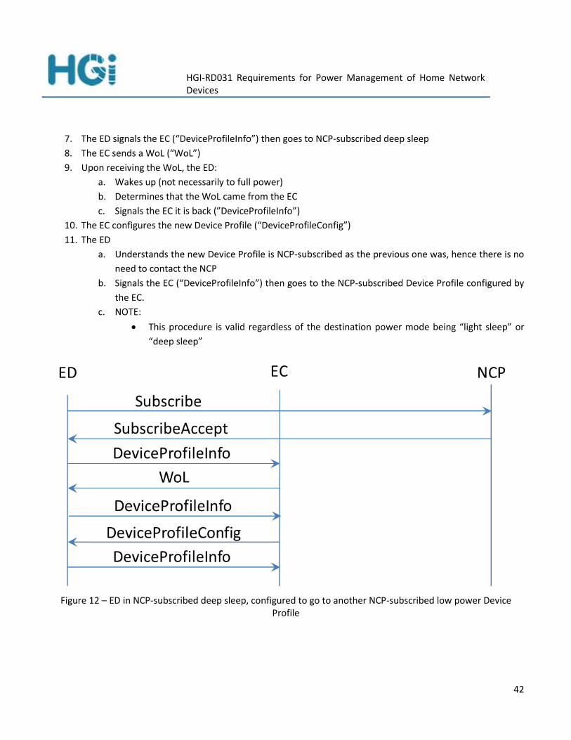
HGI-RD031 Requirements for Power Management of Home Network Devices
42
7. The ED signals the EC (“DeviceProfileInfo”) then goes to NCP-subscribed deep sleep
8. The EC sends a WoL (“WoL”)
9. Upon receiving the WoL, the ED:
a. Wakes up (not necessarily to full power)
b. Determines that the WoL came from the EC
c. Signals the EC it is back (”DeviceProfileInfo”)
10. The EC configures the new Device Profile (“DeviceProfileConfig”)
11. The ED
a. Understands the new Device Profile is NCP-subscribed as the previous one was, hence there is no
need to contact the NCP
b. Signals the EC (“DeviceProfileInfo”) then goes to the NCP-subscribed Device Profile configured by
the EC.
c. NOTE:
This procedure is valid regardless of the destination power mode being “light sleep” or
“deep sleep”
Figure 12 – ED in NCP-subscribed deep sleep, configured to go to another NCP-subscribed low power Device Profile

HGI-RD031 Requirements for Power Management of Home Network Devices
43
MANAGEMENT OF THE NCP AND EC 6.5
This Section outlines a basic scenario for TR-069 management of the NCP and EC and the related Type I / Type II
Power Aware EDs. End Devices are managed either directly by the ACS or via a TR-069 proxy for the management
protocol supported by the ED. The usual configuration for TR-069 is that the proxy resides in the Home Gateway
but this is not necessarily the only one solution. For instance, both NCP and EC could act as TR-069 proxies for the
management of non TR-069 EDs. In his case it could be reasonable to assume that NCP takes care of Type I
Devices and the EC takes care of Type II Devices (no preference for Type I + Type II End Devices) but there is no
actual requirement for this. TR-069 is Power Awareness agnostic. The only reason in favour of matching the
Power Awareness type of the proxied End Devices with the Power Awareness of the proxier could be that in case
the EC is implemented in a box that is separate from the HG and it proxies for non-TR-069 Type I Power Aware
Devices when the EC is disabled the Type I Power Aware Devices proxied by the EC become unmanageable. Figure
13 here below depicts a general scheme for Remote Management.
Figure 13 – NCP and EC remote management scenario
Management actions that the ACS could carry out on EDs include:

HGI-RD031 Requirements for Power Management of Home Network Devices
44
Configuration of the NCP-related functionalities on EDs
o Enabling / disabling the Type I Power Awareness service on each ED
o Enabling / disabling the Type II Power Awareness service on each ED
Exposing the relevant TR-069 Device table containing the list of EDs that have already made use of the
NCP service. There is no guarantee that this list is complete since there might be EDs that simply did not
yet request the NCP.
Configuration of the NCP
o Enabling / disabling the Network Connectivity Proxy service
o Disabling the NCP service should also disable Power Awareness on all of the EDs known to the
NCP
Configuration of the EC
o Enabling / disabling the Energy Controller Service
o Retrieving the list of managed EDs and their EPs
o Configuring the default EP per Device
o Configuring the EP to be used at different times of the day/day of the week
o Providing the EP list for Devices.
o Disabling the EC does not necessarily involve disabling any functionality on the EDs, since these
just receive commands from the EC about the power mode they should go to.
o Disabling the EC should cause the EC to configure ED to power modes that allow autonomous
wake up
Monitoring of NCP, EC and related EDs, to periodically read and store the current power mode and/or
power consumption values for each ED. This could be done by the ED periodically signalling to the ACS the
availability of monitoring data, for instance by means of the Periodic Statistics mechanism provided by
TR-069. These monitoring data could then be sent to higher layer systems, for instance Operation System
Support systems, to build usage patterns as well as estimate average energy consumption.

HGI-RD031 Requirements for Power Management of Home Network Devices
45
7 REQUIREMENTS
REQUIREMENTS FOR THE HG 7.1
N° Requirements
R.1 The HG MUST be able to host the NCP (Network Connectivity Proxy) function.
R.2 The HG MUST be able to host the EC (Energy Controller) function.
R.3 The HG MUST support at least Ethernet WoL as a LAN wake-up mechanism for EDs.
REQUIREMENTS FOR REMOTE MANAGEMENT 7.2
N° Requirements
R.4 The Remote Management system MUST be able to access the list of (Power Aware) Devices that have requested the NCP function at any given time.
R.5 Remote Management MUST be able to access the list of Power Aware Devices.
Remote Management MUST be able to force subscription of an ED to the NCP
R.6 Remote Management MUST be able to remove subscription of an ED from the NCP
R.7
Remote Management MUST be able to enable/disable the function of Power Awareness, i.e. the capability of going to low power mode and being woken up by user or network stimuli, on home network End Devices (EDs) as well as the HG.
R.8 Remote Management MUST be able to send an ED to any power mode.
R.9 Remote management signalling MUST be able to be conveyed not only through the LAN but also by any available out-of-band overlay network.
R.10 Remote Management MUST be able to enable/disable the NCP on the HG.
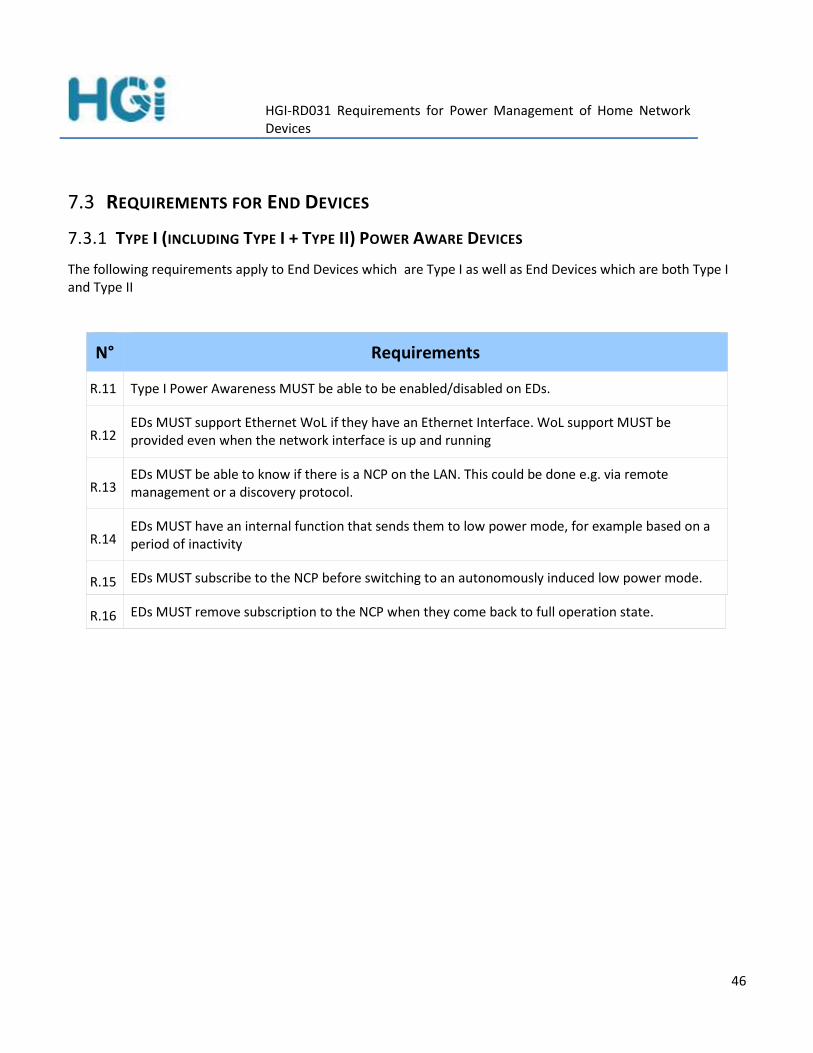
HGI-RD031 Requirements for Power Management of Home Network Devices
46
REQUIREMENTS FOR END DEVICES 7.3
7.3.1 TYPE I (INCLUDING TYPE I + TYPE II) POWER AWARE DEVICES
The following requirements apply to End Devices which are Type I as well as End Devices which are both Type I and Type II
N° Requirements
R.11 Type I Power Awareness MUST be able to be enabled/disabled on EDs.
R.12 EDs MUST support Ethernet WoL if they have an Ethernet Interface. WoL support MUST be provided even when the network interface is up and running
R.13 EDs MUST be able to know if there is a NCP on the LAN. This could be done e.g. via remote management or a discovery protocol.
R.14 T EDs MUST have an internal function that sends them to low power mode, for example based on a period of inactivity
R.15 EDs MUST subscribe to the NCP before switching to an autonomously induced low power mode.
R.16 EDs MUST remove subscription to the NCP when they come back to full operation state.

HGI-RD031 Requirements for Power Management of Home Network Devices
47
N° Requirements
R.17
Upon subscription EDs SHOULD provide the following information:
• ED Ethernet address (to send the WoL or other suitable wake up signal)
• ED IP address
• DHCP Server IP address
• DHCP timeout
• Time left before next DHCP renewal
• If any TCP/IP sessions are open, for each of them:
• The TX / RX port number
• The timeout
• Other protocols that are to be proxied, with the associated parameters.
NOTE: the detailed protocols for requesting NCP functionality are out of scope of this specification. Parameters that are expected to remain constant over more than one subscription could be configured in other way, e.g. by a special subscription message or by remote management.
R.18 If a sleeping ED can periodically wake-up autonomously, then the value of this time period MUST be exposed to, and be able to be configured by, the Management System / Energy Controller.
R.19 The ED MUST be able to determine which device sent the WoL. This is necessary in case there are more devices that are able to send the WoL (for instance NCP ad EC, but not limiting to this)
R.20 In case an ED receives a request from the NCP and one from the EC at the same time serving the
NCP request MUST come before transitioning to the EC specified Device profile.
7.3.2 TYPE II (INCLUDING TYPE I + TYPE II) POWER AWARE DEVICES
The following requirements apply to End Devices which are Type II as well as End Devices which are both Type I and Type II

HGI-RD031 Requirements for Power Management of Home Network Devices
48
No Requirements
R.21
Energy controllable EDs MUST be able to send the following information to the EC on request:
Device ID
List of the available Device Profiles (DPs)
The current Power State
The current active DP
The latest requested DP (set by the EC; if the ED accepts to transition to this DP, the ED updates the current active DP, otherwise it ignores the request).
Each DP MUST contain:
List of services supported in the DP (e.g. ‘LIVE’, ‘VOD’) (free-form labels)
Power consumption
Timer values for transitioning to the other DPs of the device (e.g. the delays before device will move to a specified lower power DP).
For these functions, a non-normative data model example for the EC can be found in Appendix B.
R.22
Energy Controllable EDs MUST be able to accept DP change requests from the EC.
The ED MUST transition to the requested DP as soon as possible (unless a currently active service is not included in the DP, in this case the ED is free to ignore the request).
R.23
Energy controllable EDs MUST maintain their current DP related information, and a time stamped log of all DP changes. This MUST be available to the EC on request.
EDs MUST send all DP state changes to the EC as notifications.
EDs may autonomously change DP, but they MUST maintain current their DP related information as listed in R.21 at all times.

HGI-RD031 Requirements for Power Management of Home Network Devices
49
REQUIREMENTS FOR THE NETWORK CONNECTIVITY PROXY FUNCTION 7.4
N° Requirements
R.24
The NCP MUST support a proxy function for at least the following protocols:
ICMP: ping response3
DHCP: renewal of the DHCP lease
TCP: keepalive
Note: a PPP keepalive proxy is not needed as the PPP connection terminates in the HG, not in an ED.
R.25 The NCP MUST buffer all incoming traffic destined for a sleeping ED other than the proxied protocols.
R.26 The NCP MUST send a WoL or other suitable wake up signal to the appropriate device as soon as traffic that cannot be proxied is detected.
R.27 The NCP MUST explicitly accept or reject each proxy request from an ED.
R.28 The NCP MUST provide the list of End Devices that have requested the NCP function to the Remote Management system.
REQUIREMENTS FOR THE ENERGY CONTROLLER FUNCTION 7.5
N° Requirements
R.29 Only one EC MUST be in control of any given device at any one time.
R.30 The EC MUST provide a remote management API.
R.31 The EC MUST attempt to discover devices in the home network on start-up and at regular intervals thereafter, by scanning the HN using one or more device discovery methods.
3 ICMP ping messages are commonly used for keepalive and troubleshooting. While keepalive usage is in line with the
concept of NCP, use of ICMP ping to troubleshoot a device in low power could provide unexpected results. For this reason users must be aware of the power mode of the devices they are going to test. Disabling both NCP and Power Awareness is advisable when troubleshooting End Devices.

HGI-RD031 Requirements for Power Management of Home Network Devices
50
R.32 The EC MUST request the DP information listed in R.21from each discovered device. The EC subsequently only manages devices that actually respond with such information.
R.33 The EC MUST be able to request a device to change to a different DP (e.g. via an API /data model).
R.34
The EC MUST be able to issue a WoL or other suitable wake up signal before requesting a new DP for a Type II or Type I + Type II Power Aware device. This includes the capability of determining whether the Device Profile for this Power Aware Device requires sending a WoL or other suitable wake up signal

HGI-RD031 Requirements for Power Management of Home Network Devices
51
8 BIBLIOGRAPHY
Home Gateway Initiative HGI-RD001-R2.01: “Home Gateway Technical Requirements: Residential Profile”, April 2008.
Home Gateway Initiative HGI-RD009-R3: “HGI Requirements for an energy efficient Home Gateway”, October 2010.
Home Gateway Initiative HGI-GD017-R3: “Use Cases and Architecture for a Home Energy Management Service”, August 2011.
“REsidential MOnitoring to DEcrease Energy use and Carbon Emissions in Europe” – REMODECE project, http://remodece.isr.uc.pt/.
“Standby and off-mode Energy Losses In New Appliances measured in shops” – SELINA project, http://www.selina-project.eu/ – EU Grant Nº IEE/07/563/SI2.499206.
Martin Lindinger, Ernst Schmautzer, Rene Braunstein, Christian Elbe: "Energy savings evaluation tool", Standby Workshop 2010, http://www.selina-project.eu/redactie/popups/pubs/2010-standby-lindinger.pdf .
“low Energy COnsumption NETworks” – ECONET project, http://www.econet.eu – European Commission Seventh Framework Program, contract number INFSO-ICT-258454.
European Commission: “Commission Regulation (EC) No 1275/2008 implementing Directive 2005/32/EC of the European Parliament and of the Council with regard to ecodesign requirements for standby and off mode electric power consumption of electrical and electronic household and office equipment”, 17 December 2008.
European Commission: “Commission Regulation (EU) No 801/2013 amending Regulation (EC) No 1275/2008 with regard to ecodesign requirements for standby, off mode electric power consumption of electrical and electronic household and office equipment, and amending Regulation (EC) No 642/2009 with regard to ecodesign requirements for televisions”, ” 22 August 2013.
ITU-T L.1310 “Energy Efficiency Metrics and Measurement Methods for Telecommunications Equipment”, http://www.itu.int/rec/T-REC-L.1310-201211-I/en, November 2012.
ITU-T L-Sup1 1310: “Supplement on energy efficiency for telecommunication equipment”, http://www.itu.int/rec/T-REC-L.Sup1-201302-I, April 2013.
UPnP Forum: “UPnP Device Architecture 1.1”, http://upnp.org/specs/arch/UPnP-arch-DeviceArchitecture-v1.1.pdf. October 2008.
UPnP Forum: “UPnP Low Power 1.0”, http://upnp.org/specs/lp/UPnP-lp-LPArchitecture-v1.pdf, August 2007.
UPnP Forum: “UPnP Low Power Device:1”, Service Template Version 1.01, http://upnp.org/specs/lp/UPnP-lp-LowPower-v1-Service.pdf, August 2007.

HGI-RD031 Requirements for Power Management of Home Network Devices
52
UPnP Forum: “UPnP Low Power Proxy:1”, Service Template Version 1.01, http://upnp.org/specs/lp/UPnP-lp-LowPowerProxy-v1-Service.pdf, August 2007.
UPnP Forum: “UPnP Energy Management:1”, Service Template version 2.00, http://upnp.org/specs/lp/UPnP-lp-EnergyManagement-v1-Service.pdf, August 2013.
Raffaele Bolla, Maurizio Giribaldi, Rafiullah Khan and Matteo Repetto: "Design and Implementation of Cooperative Network Connectivity Proxy Using Universal Plug and Play" – The Future Internet Lecture Notes in Computer Science Volume 7858, 2013, pp 323-335 [http://link.springer.com/chapter/10.1007%2F978-3-642-38082-2_26].
UPnP Forum, “Basic Management:2”, http://upnp.org/specs/dm/UPnP-dm-BasicManagement-v2-Service.pdf, February 2012.
UPnP Forum, “Configuration Management:2”, http://upnp.org/specs/dm/UPnP-dm-ConfigurationManagement-v2-Service.pdf], March 2013.
UPnP Forum, “Software Management:2”, http://upnp.org/specs/dm/UPnP-dm-SoftwareManagement-v2-Service.pdf], February 2012.
Broadband Forum: “TR-069 CPE Wan Management Protocol”, http://www.broadband-forum.org/technical/download/TR-069_Amendment-5.pdf, November 2013.
Broadband Forum,”TR-106 Data Model Template for TR-069-Enabled Devices”, http://www.broadband-forum.org/technical/download/TR-106_Amendment-6.pdf, July 2011.
Broadband Forum: “TR-181 Device Data Model for TR-069”, http://www.broadband-forum.org/technical/download/TR-181_Issue-2_Amendment-7.pdf, November 2013.
AMD, “Magic Packet Technology,” Whitepaper, http://www.swas.polito.it/services/polisave/AMD_mp.pdf, November 1995.

HGI-RD031 Requirements for Power Management of Home Network Devices
53
9 APPENDIX A : NCP IMPLEMENTATION NOTES
The HGI NCP/EC requirements are technology agnostic, but implementing them will require specific protocols
some of which are yet to be designed. This might require designing a new standard, or extending an existing one
e.g. within the UPnP framework. The UPnP framework is widely used with Home Network devices and, more
specifically, UPnP Energymanagement:1 currently represents the state of the art in power management.
Therefore it might be appropriate to consider UPnP Energymanagement:1 as a suitable starting point for
implementation of the HGI NCP/EC.
The connectivity related features of the Network Connectivity Proxy (intercepting traffic, proxying for some
protocols and buffering the non proxy-able ones) are totally unknown in UPnP Energymanagement:1 so they
might be standardized as a separate UPnP service. However, since this functionality is defined at the moment as
monolithic, allowing no configuration then there appears to be no need for UPnP standardization of a device like
this. What appear of interest for NCP, instead, are the subscription / subscription release actions of the UPnP
Energymanagement:1 device. These map well to the Subscribe / Unsubscribe messages defined for NCP so much
so that an implementation of NCP as an UPnP Energymanagement:1 Device could be feasible, restricted to these
aspects. The NCP should also support an implementation as an UPnP Energymanagement:1 CP for its capability of
sending WoL. In this case the physical devices that ask for the NCP Service could also support the UPnP
Energymanagement:1 Device functionality for the capability of describing the characteristics of the WoL signal
they should receive. It has to be pointed out, though, that the mandatory action of the UPnP
Energymanagement:1 Device, i.e. GetInterfaceInfo(), would NOT need to be supported because no CP would be
interested in knowing the power mode of the NCP as an UPnP Energymanagemtn:1 Device, since this is expected
to be always up. On the other hand, the NCP as an UPnP Energymanagement:1 CP would not be interested in
knowing the power mode of the UPnP Energymanagement:1 interfaces it has to send the WoL to because this
service was requested to the NCP, hence it is the requester’s responsibility to provide a suitable interface. In the
end, the NCP “as is” does not seem to be immediately implementable as an UPnP Energymanagement:1 Device /
CP, though further studies seem to be motivated base on the commonalities that were highlighted above.
Based on the above there are a couple of options for implementing the NCP:
An implementation based on UPnP that is able to overcome the limitations that were listed before. This
would possibly require generalization of the current NCP functionality but would provide the advantage of
developing in a standardized and well known environment.
Using another technology which is nothing to do with UPnP. This again would need to be standardized for
interoperability reasons. In this case the solution could be carefully tailored on the existing NCP but the
standardization effort would be huge.

HGI-RD031 Requirements for Power Management of Home Network Devices
54
10 APPENDIX B: EC EXAMPLE DATA MODEL
This section provides an example (pseudo) data model for EDs cooperating with the Energy Controller.
The ED data model should contain the device’s available power states with their associated functional capabilities and energy consumption. Additional optional parameters include profile transition delays and associated energy costs.
The following pseudo data model is proposed to enable standardization of ED power consumption and profile data access and management.
Name Type Write Description Example
Device.Services.energyservicename. object - Main energy object -
DeviceNumberOfEntries unsignedInt - Number of entries in the Device table
-
.Device.{i}. object - This table of End Devices managed by the Energy Controller
-
.Device.{i}.DeviceInfo. object - This object contains general device information
-
Description string - A short name of the ED (human readable string).
Enumeration of :
"Gateway"
"STB"
"PC"
"PLC"
etc.
"STB"
ImageURL string(256) - Image file -
.Device.{i}.LAN. object - This object contains parameters relating to IP based LAN connectivity of a device.
-
IPAddress string - The current IP address assigned to this interface
-
MACAddress string - The physical address of this -

HGI-RD031 Requirements for Power Management of Home Network Devices
55
interface
.Device.{i}.Energy. object - This object contains parameters relating to Device Profile information of a device
-
CurrentProfile string - Current state or Device Profile of the device. Enumeration of: "DOWN" ”INIT” “ERROR” “DISABLED” "Standby" …"ActiveStandby”, "FastStandby", ”DeepStandby", ...
Or any additional operational DP, such as
“MENU’, “LIVE”, “VOD_SD”, “DMSEth”, “DMSWiFi”, etc.
“MENU”, “LIVE”, “VOD_SD”
RequestedProfile string W Requested Device Profile (by the Energy Controller) for the device. If the value is different from "None" (and from the current profile), the device must be performing a transition to this Device Profile. Enumeration of: (same as operational DPs in CurrentProfile)
“ActiveStandby”
.Device.{i}.Device.ProfilesSupported. object - This object defines the complete set of available Device Profiles
-
ProfileNumberOfEntries unsignedInt - Number of entries in the Device Profile table
-
.Device.{i}.Device.ProfilesSupported.Profile.{i}.
object - Each instance of this object defines a possible Device Profile
-
Name string - Name of the Device Profile. Enumeration of: (same as operational DPs in CurrentProfile)
-

HGI-RD031 Requirements for Power Management of Home Network Devices
56
Services string(256) - Comma-separated list of the services immediately available in this Device Profile. Each value is a short name identifying a function.
VoD, Live
Power unsignedInt - Estimated power consumption (milliwatt) when the device is in this Device Profile
TransitionNumberOfEntries unsignedInt - Number of entries in the Transition table
-
.Device.{i}.Device.ProfilesSupported.Profile.{i}.Transition.{i}.
object - Each instance of this object define a possible transition from the Device Profile defined
-
Name string - The name of the reachable Device Profile. Enumeration of: (same as operational DPs in CurrentProfile)
-
Timer unsignedInt - Time in milliseconds the device must stay in the starting Device Profile without user action nor scheduled action before passing automatically to this one. A value of 0 indicates that the device does not switch automatically to this Device Profile. N.B. For each DP definition, this value is a non-zero value for only one or zero instances of transition.
-
Delay unsignedInt - Time in milliseconds necessary to perform the transition
-
Cost unsignedInt - Energy cost in milliwatt to perform the transition.
A first plane contains the ED description.
A second plane is then devoted to the Device Profile state list enriched by timeout delay (if any), transition energy consumption and duration. The proposed solution (which by no means should be considered as a definitive one) is given as an example to show the full range of data that describes the Device Profile state diagram.
In this solution we propose to limit the amount of data in the Data Model by promoting a dialogue with the ED. Thus the number of required fields depends only on the state number and not on possible transitions.

HGI-RD031 Requirements for Power Management of Home Network Devices
57
The Data Model includes one unique field supporting Write access:
The RequestedProfile is used to request a profile change of the ED.
For each state we obtain from the Data Model five values (Read access only except for time-out Value):
1. The corresponding Services profile
2. The expected Power Consumption of the ED in this state (directly or indirectly)
3. Then three attributes of the transition (if any) leading to this state from the current one:
a. Optionally, the time out delay to transition to the state from the current one.
b. The transition expected delay
c. The transition expected energy cost.
This results in a fixed size data model for each ED.

HGI-RD031 Requirements for Power Management of Home Network Devices
58
11 APPENDIX C: SUMMARY OF EU PROJECTS REMODECE AND SELINA
THE REMODECE PROJECT 11.1
Energy consumption measurements carried out for a two week period in 1300 houses spread all over Europe,
were used to estimate the average yearly energy consumption of a European household. To do this a usage
pattern was built, taking account of the two week usage pattern but then augmenting this by assumptions about
‘annual’ behaviour, (for instance, lamps, PCs and Television sets would probably be turned off for a couple of
weeks’ holiday period, whereas refrigerators would not). This estimated yearly energy consumption per product
category was then averaged based on the percentage of households using each product. More specifically, a
weighted average per country was calculated. Figure 14 summarises the REMODECE results.
Figure 14 – Typical European Household Yearly Electrical Energy Consumption
The REMODECE project excluded electric space heating and hot-water heating from its analysis. This might be
reasonable from the point of view of assessing standby consumption as such devices probably switch directly
between on and off, without ever transitioning to a standby state. However this will give a distorted view of total
energy consumption. Excluding these (possibly major) energy consumers, the main energy users by

HGI-RD031 Requirements for Power Management of Home Network Devices
59
activity/device type was: Refrigeration 28%, Lighting 18%, washing/drying 16%, Cooking 11%, PCs + Accessories
12% and TV 9%.
Lamps, Information Technology devices (PC & accessories) and Television sets are together responsible for as
much as 40 % of the European average yearly energy consumption (again excluding space and water heating).
Home Gateways are not explicitly mentioned in this analysis but some of their most important components are,
like routers or Wi-Fi access points, so it can be assumed they are included in this analysis.
REMODECE also examined the standby behaviour of a number of product classes. These results are contained in
Table 1 below.
Appliance
Devices/House
[Percent]
(All Participating Countries
Weighted Average)
Device Measured Yearly Standby Consumption
[kWh/household]
(Averaged over all participating countries and
weighted by Devices/House)
Standby as Share of Devices’ Yearly Consumption
[Percent]
(Averaged over all participating
countries)
Chargers - 0,1 1,1 %
Refrigerator without freezer
34,8 % 1,2 0,9 %
Refrigerator with freezer 78,9 % 2,9 0,8 %
Freezer 49,5 % 0,9 0,3 %
Washing machine 94,3 % 1,8 1,0 %
Clothes dryer 31,8 % 0,6 0,6 %
Dishwasher 60,8 % 1,2 0,9 %
Desktop PC including monitor
78,9 % 20,1 9,2 %

HGI-RD031 Requirements for Power Management of Home Network Devices
60
Laptop PC 41,9 % 2,5 10,7 %
Router for Internet 47,9 % 23,7 85 %
Wireless access point 51,0 % 20,1 85 %
Printer 66,9 % 21,9 99,9 %
TV CRT 92,6 % 11,7 10,2 %
TV LCD 22,5 % 1,5 3,6 %
TV Plasma 8,8 % 0,4 1,2 %
DVD recorder/player 66,6 % 1,8 11,8 %
Hi-Fi 71,5 % 5,7 17,4 %
Satellite/cable/air set top box
41,1 % 26,3 85 %
Air conditioner 16,8 % 0,8 1,4 %
Oven/cooker 80,1 % 5,2 2,3 %
Microwave oven 66,6 % 4,2 19,5 %
Water kettle 50,0 % 0,1 0,2 %
Vacuum cleaner - 0,5 0,7 %
Lamps - 23,2 4,6 %
Total 178,6 6,6 %
Table 1 – European Average Standby power consumption per Appliance
It is interesting to note from Table 1 that the average standby power consumption is only 6.6 % of the power in
active state. However, there are significant differences between types, ranging from 0.2% for water kettles to
99.9% for printers, with a number of other Consumer Electronic devices being about 85%. A specific comment
about STBs: for this product the distinction should probably be made between satellite STBs, that usually never go
to standby and for which the 85% percentage seems to be appropriate, and xDSL STBs that in fact offer low power
operation modes. It also should be taken into account that low power xDSL STBs were probably not available at
the time when the project was carried out. Based on this table, just reducing the standby power consumption of

HGI-RD031 Requirements for Power Management of Home Network Devices
61
the devices with particularly high standby consumption to a value typical of the majority of other devices (e.g. 10
%) would significantly reduce the total power consumption figure.
The greatest benefits in avoiding standby energy wastage could be achieved by:
Redesigning STBs to use solid state memory
Switching STBs off completely when not in use
Redesigning the WLAN and Router to transition nearly all components to off-mode when no data is
transported and/or at night, but with a fast restart when a call comes in or the user starts a WLAN client
Switching off printers automatically when not in use
Switching off the desktop PC and monitor when not in use.
The REMODECE project also estimated how much energy could be saved by using the most energy-efficient
products available at the time. They estimated that the household consumption could be reduced by over 50%
(from 2695 kWh to 1367 kWh per year) without changing user behaviour or introducing any new technology.
Finally, though a standby consumption figure of 6.6 % (of the annual total) might sound low, even this adds up to
more than 10 million tons of CO2 per year.
It should be pointed out that these considerations are out of scope for HGI energy management Phase 2 which
deals with network wide policies rather than device technology. From the point of view of HGI energy
management Phase 2, then, the REMODECE project provides the 6.6 % value as an indication of how much energy
could be saved by keeping the home network devices in low power as long as possible. This is exactly the goal of
HGI NCP / EC.
THE SELINA PROJECT 11.2
The EU research project SELINA (website http://www.selina-project.eu/ ) went into greater detail than
REMODECE but the basic conclusions of the latter were not changed.
SELINA made over 6000 measurements of standby power of many classes of products found in shops in the 2nd
half of 2009 and 1st half of 2010. From these measurements it was possible to determine the range of power
consumption - from "best of breed" to "worst case" - for each product type. Whereas REMODECE simply
considered “full power” “and “standby” states, SELINA took into account a more comprehensive set of power
states, as listed in Table 2 below, and gives a comparison between the SELINA findings and EU Regulation
1275/2008 [8] which actually specifies power consumption limits for standby modes:

HGI-RD031 Requirements for Power Management of Home Network Devices
62
SELINA
EU Regulation 1275/2008 [8]
Mode 2010 limit (W)
2013 limit (W)
Off-mode In this mode the appliance does not offer any functions but remains connected to a power source. It might however still consume some residual power.
Off-mode 1 0,5
Passive standby mode / Delay-Start
In this mode the appliance is put into low power mode by a certain means such as a switch or remote control, and still provides one of the basic functions. This mode is identical to that of DGENER ErP Lot 26.
Reactivation function provided by a soft or hard switch, remote control, internal sensor or timer,
Continuity functions: Information or status displays including clocks; Information storage (volatile memory); Sensor-based safety functions
Standby ("Reactivation possible")
1 0,5
Standby ("Information or status on display")
2 1
Networked standby mode
In this mode the appliance provides reactivation via network command, not a main function, and it is identical to DGENER ErP Lot 26 networked standby mode definition [8].

HGI-RD031 Requirements for Power Management of Home Network Devices
63
Active standby mode
Active Low (active standby) is when the appliance is on but not performing its main function. For example, the DVD may be on but is not playing or recording. This mode is usually only present in devices where there is:
a mechanical function which is not active (e.g. DVD drive or motor) but where power circuits are on, or
a battery and the device is charging or
a quiescent power state (audio amplifier with no audio signal)
downloading data (STB or TV updating Electronic Program Guide or software)
In-Use In this mode the appliance provides one or more of its main functions. During the measurement campaign, all parties were asked to measure as many modes as possible in order to achieve the maximum information about product power consumption.
Active mode
Table 2 – European Regulations Power Consumption Limits
Table 3 below summarizes the power consumption measurements for each product class in each of the above
specified power states. This table is derived from a number of tables published by the SELINA project.
Pro
du
ct Class
Off-M
od
e [W
}
De
lay-Start [W
}
Passive
stand
by
[W}
Ne
two
rk Stand
by
[W}
Active
Stand
by
[W}
In-U
se [W
}
Audio 1.11 2.79 2.64 10.37 10.97 12.55
Building & Infrastructure
0.04 1.3 1.4
Cleaning 0.12 1.33 3.05 671.94
Computer 0.86 0.19 2.78 1.13 8.66

HGI-RD031 Requirements for Power Management of Home Network Devices
64
Cooking 0.22 1.76 1.74 1.75 61.99
Cooking-Cutting
0.18 1.59 1.5 0.39 66.39
Display 0.46 12.3 1.25 0.44 2.08 30.98
DVD/VCR 0.51 2.63 9.48 7.11
EPS 0.56 0.37
HVAC 0.33 2.92 1.54 1.62 20.39
Imaging 0.52 10.04 5.66 10.16
Lighting 3.7
Major Appliance
0.33 3 2.18 2.08
Network 6.06 5.42 3.55 5.29
Personal Care 0.25 1.37 3.15
Power 1.45 0.36
Set-top-boxes 0.1 1.47 4.07 9.7 13.74
Telephony 0.55 0.12 1.25 1.88
VCR/DVD 1.43 18.23
Table 3– European Average Power Consumption (in Watt) per Appliance
SELINA also examined the variance of these statistics by class of appliance as shown in Figure 15 below. This
clearly shows that for most device classes the average standby power is close to the median, and 75% of devices
generally do not use more than twice the average standby power. That allows use of the average value as a useful
KPI. A few device classes do not fit this pattern because of a few devices with very large values: Imaging, Display
and VCRs stand out. The standby results show high input power values especially for Network devices, Set-Top-
Boxes and VCR/DVDs. The average value for the imaging class was highly influenced by some appliances with very
high values. So if the median is taken into account, the standby input power seems relatively low.
SELINA also cites (see [6]) the value of 6% power wastage in the home due to standby of consumer equipment,
based on 2004 results by Bertoldi.

HGI-RD031 Requirements for Power Management of Home Network Devices
65
Figure 15 – SELINA measurements of standby power usage in various product classes
11.2.1 CONCLUSIONS AND PROPOSALS
The main points highlighted in the above work are:
1. The average power consumption in standby modes is about 6% of the power in active state, even though
the product classes used by SELINA are not exactly the same as those used by REMODECE
2. Individual values are widely dispersed around the average
3. A limited set of Consumer Electronic appliances (line printers, PCs, routers, Wi-Fi Access Points, screens
and Television sets) heavily influences the cumulative amount of standby power.
4. In many cases Networked Standby allows substantial power savings with respect to In Use or Active
Standby
The immediate conclusion is that technological advancements leading to reduction of power consumed in
standby by this range of products would significantly impact the overall power consumption figure without
modifying usage patterns.
Further decreases could then be obtained by influencing user habits and/or using ICT to automatically modify the
way energy is used. This approach could be applied to standby as well as full power states of a wide number of
products. For example, lights could automatically be switched off when no-one had been in a room for 5 minutes;
this might save a significant proportion of the 18% usage reported by REMODECE. A refrigerator compressor
could be designed to cycle colder then switch off completely for a while (not circulating coolant) thereby reducing
the 28%. TVs could be switched off automatically when no-one was in the room.
The management (policy) examples described fit well with the scope of HGI energy management Phase 2. From
this point of view the main conclusions appear to be:
The average standby power is (again) about 6% of the active power, making it worthwhile to keep the
home network devices in low power as long as possible

HGI-RD031 Requirements for Power Management of Home Network Devices
66
Power consumption of devices in networked standby in many cases is comparable to that of traditional
standby, making the prospective energy saving more appealing. For the sake of clarity Networked
Standby is the power state where devices are able to be woken up remotely, i.e. via a network wake up
signal. This usually, but not necessarily, adds up to local wake up via device local GUI.