requirement engineering with urn: integrating...
TRANSCRIPT
Requirement Engineering with URN:
Integrating Goals and Scenarios
Jean-François Roy
Thesis submitted to the
Faculty of Graduate and Postdoctoral Studies
in partial fulfillment of the requirements for the degree of
Master of Computer Science
Under the auspices of the Ottawa-Carleton Institute for Computer Science
University of Ottawa
Ottawa, Ontario, Canada
March 2007
© Jean-François Roy, Ottawa, Canada, 2007
i
Abstract .
The User Requirements Notation (URN) is an emerging standard that combines two
views: the Goal-oriented Requirement Language (GRL) and the Use Case Map (UCM)
notation. This standard intends to combine goals and scenarios for expressing and reason-
ing about functional and non-functional requirements. Although tools exist in isolation
for both views, they are currently not meant to work together, hence hindering the devel-
opment and adoption of URN. This thesis presents Eclipse-based tool support for inte-
grated goal and scenario modelling based on URN. A metamodel that integrates GRL
with an existing UCM metamodel is given, together with a detailed description of the tool
capabilities. New and automated analysis approaches are also introduced, which exploit
integrated URN models. The approaches that are described include quantitative goal
evaluations, stakeholder evaluations, novel GRL strategies, and links between the URN
views. In addition, this thesis presents an approach to link GRL models to external re-
quirements, also supported by our tool. Finally, the integrated URN approach is illus-
trated and validated using case studies.

ii
Acknowledgment
I would like to express my deepest gratitude to my supervisor, Dr Daniel Amyot, for his
guidance, support, comments and encouragement. His advices greatly improved this the-
sis and I am very fortunate to have been supervised by him. Merci pour tout Daniel!
I own special thanks to Jason Kealey for his ideas, inspiring discussions that we
have had together, and his contributions to jUCMNav. Also, I would like to thank Gunter
Mussbacher for his useful comments and assistance.
I would like to thank Etienne Tremblay, Jean-Philippe Daigle, Jordan McManus
and Olivier Clift-Noël for their contributions to jUCMNav. Also, thank you to Jacques
Sincennes for his help.
I would like to thank for their financial support the Natural Science and Engineer-
ing Research Council of Canada (Strategic and Discovery Grant Programs) and the On-
tario Research Network on Electronic Commerce.
Finally, I would like to thank my family for their constant support and love. In
addition, I own a special thanks to my parents for their financial support during my stud-
ies.

iii
Table of Contents
Abstract .......................................................................................................................i
Acknowledgment ...........................................................................................................ii
Table of Contents ........................................................................................................ iii
List of Figures...............................................................................................................vi
List of Tables ..............................................................................................................viii
List of Acronyms ..........................................................................................................ix
Chapter 1 Introduction ................................................................................................1 1.1 Motivation .......................................................................................................1 1.2 Thesis Goals ....................................................................................................2
1.3 Contributions ...................................................................................................2 1.4 Thesis Outline ..................................................................................................4
Chapter 2 Background.................................................................................................5 2.1 Goal-Oriented Requirements Engineering........................................................5
2.1.1 NFR Framework ....................................................................................................5 2.1.2 i* Framework .........................................................................................................9
2.2 User Requirement Notation (URN).................................................................12 2.2.1 Goal-oriented Requirement Language...................................................................12 2.2.2 Use Case Map Notation........................................................................................16 2.2.3 Combining Goals and Scenarios ...........................................................................18
2.3 URN-Related Tools ........................................................................................20 2.3.1 Goal-oriented Requirement Engineering Tools .....................................................20 2.3.2 Use Case Maps Tools ...........................................................................................26
2.4 Requirements Management System ................................................................29 2.4.1 Telelogic DOORS ................................................................................................29 2.4.2 Importing UCM Models into DOORS ..................................................................31
2.5 Chapter Summary ..........................................................................................32
Chapter 3 Integrated Tool Support for URN............................................................33 3.1 Requirements and Rationale for an Integrated URN Tool...............................33

iv
3.2 An Integrated URN Metamodel ......................................................................36 3.2.1 Abstract URN Metamodel ....................................................................................36 3.2.2 Implementation Metamodel ..................................................................................39
3.3 jUCMNav as an Integrated URN Tool............................................................44 3.3.1 Architecture and Implementation..........................................................................44 3.3.2 Basic Editing Features for GRL............................................................................46
3.4 Goals Catalogues...........................................................................................49 3.4.1 Catalogue Design and Implementation..................................................................49 3.4.2 Example of a Security Catalogue ..........................................................................50
3.5 Model Creation Example: a Client-Server Application...................................52 3.6 Chapter Summary ..........................................................................................55
Chapter 4 Analysis of URN Models...........................................................................56 4.1 A New Evaluation Algorithm..........................................................................56
4.1.1 From Qualitative to Quantitative Evaluations........................................................56 4.1.2 Algorithm.............................................................................................................57
4.2 GRL Strategies...............................................................................................61 4.2.1 Intentional Element Labels ...................................................................................61 4.2.2 Actor Labels.........................................................................................................65
4.3 Using GRL Analysis.......................................................................................67 4.4 Linking Goals and Scenarios: URN Internal Links.........................................70
4.4.1 Link Definition and Implementation .....................................................................70 4.4.2 Using URN Links.................................................................................................72
4.5 Chapter Summary ..........................................................................................74
Chapter 5 Linking and Evolving Requirements .......................................................75 5.1 Exporting URN Models to DOORS ................................................................75
5.1.1 Principles and Requirements for Exporting URN..................................................75 5.1.2 Implementation in jUCMNav ...............................................................................76
5.2 Importing URN Model in DOORS..................................................................79 5.2.1 DOORS Structure.................................................................................................79 5.2.2 Internal Links .......................................................................................................81 5.2.3 DXL Library API .................................................................................................82
5.3 Using URN Models in DOORS.......................................................................92 5.3.1 Linking to DOORS...............................................................................................92 5.3.2 Model Synchronization.........................................................................................95
5.4 Chapter Summary ..........................................................................................96
Chapter 6 Case Study: Credit Card Gateway...........................................................97 6.1 Modelling Using URN....................................................................................97
6.1.1 Customers-Merchants Modelling..........................................................................98 6.1.2 Potential High-Level Architectures.......................................................................99 6.1.3 GRL Model........................................................................................................103
v
6.2 Evolving the Credit Card Gateway Model ....................................................106 6.2.1 Creating URN Links...........................................................................................106 6.2.2 Adding a Secure Transaction Catalogue..............................................................107
6.3 Analyzing the Model ....................................................................................110 6.3.1 Evaluation of Intentional Elements .....................................................................111 6.3.2 Evaluation of Actors...........................................................................................111
6.4 Managing Requirements in DOORS.............................................................113 6.4.1 Importing the Initial URN Model........................................................................114 6.4.2 Updating a URN Model in DOORS....................................................................115
6.5 Chapter Summary ........................................................................................117
Chapter 7 Conclusions .............................................................................................119 7.1 Discussion ...................................................................................................119
7.1.1 Goals and Contributions .....................................................................................119 7.1.2 Tool Validation ..................................................................................................122
7.2 Future Work.................................................................................................123
References. .................................................................................................................125
Appendix A: GRL Catalogue Schema......................................................................129
Appendix B: Case Study Strategies ..........................................................................131

vi
List of Figures
Figure 1. NFR Framework: Softgoal Interdependency Graph for Performance ............7 Figure 2. i* Strategic Dependency Model for an Electronic Payment System ............10 Figure 3. i* Strategic Rationale Model for an Electronic Payment System.................11 Figure 4. Summary of the GRL Concrete Notation....................................................12 Figure 5. Evaluation of Candidate Solutions using GRL............................................13 Figure 6. UCM Model of an Evaluation System........................................................16 Figure 7. Summary of a Subset of the UCM Concrete Notation.................................17 Figure 8. URN as a Missing Piece of the Modelling Puzzle.......................................18 Figure 9. Strategic Dependencies Model in OME......................................................20 Figure 10. GRL Modelling with SanDrila for MS Visio ..........................................22 Figure 11. Goal Modelling with the TAOM4E Tool................................................23 Figure 12. Goal Modelling with GRTool.................................................................24 Figure 13. jUCMNav User Interface for UCM Modelling .......................................28 Figure 14. UCM Model in Telelogic DOORS .........................................................30 Figure 15. Integrating UCM and DOORS................................................................31 Figure 16. High-Level Goals for an Integrated URN Tool .......................................34 Figure 17. Implementation Solutions.......................................................................34 Figure 18. Main Elements of the Abstract URN/GRL Metamodel ...........................37 Figure 19. GRL Links Metamodel...........................................................................38 Figure 20. Main Elements of the Abstract URN/UCM Metamodel ..........................39 Figure 21. Main Packages in URN Metamodels ......................................................40 Figure 22. Common Interface for URN from URNcore Package .............................41 Figure 23. Main Elements of the Implementation GRL Metamodel .........................42 Figure 24. Main Elements of the Implementation UCM Metamodel ........................43 Figure 25. Element of the URN Implementation Package........................................44 Figure 26. Overview of jUCMNav Architecture and Dependencies.........................45 Figure 27. GRL Editor in jUCMNav .......................................................................48 Figure 28. GRL Security Catalogue.........................................................................51 Figure 29. High-level View of Actor Concerns........................................................53 Figure 30. Integration of the Security Catalogue......................................................54 Figure 31. Web Request UCM Model .....................................................................54 Figure 32. Decomposition Evaluations ....................................................................58 Figure 33. Contribution Evaluations........................................................................60 Figure 34. Dependency Evaluations ........................................................................61 Figure 35. Abstract GRL Strategies Metamodel ......................................................62 Figure 36. Modification of Evaluation for a GRL Strategy ......................................63 Figure 37. Actor Evaluation Labels .........................................................................67 Figure 38. Password – Encryption – Training Strategy in jUCMNav.......................68 Figure 39. URN Links Definition in jUCMNav.......................................................71

vii
Figure 40. UCM for Authentication Mechanisms ....................................................72 Figure 41. UCM Views Based on the Selected GRL Strategy..................................73 Figure 42. DXL Script for a GRL Diagram with a Strategy .....................................78 Figure 43. High-Level View of URN Structure in DOORS .....................................79 Figure 44. Metamodel of GRL in DOORS ..............................................................80 Figure 45. Internal Links in the DOORS URN Folder .............................................82 Figure 46. Intentional Elements and Intentional Element Associations Modules......85 Figure 47. GRL Diagrams Module ..........................................................................89 Figure 48. Strategies Module...................................................................................91 Figure 49. URN Links in DOORS...........................................................................91 Figure 50. Typical External URN Links ..................................................................93 Figure 51. External and Internal Links for GRL in DOORS ....................................94 Figure 52. Buying Process between Customer and Merchant...................................98 Figure 53. Dependencies between Merchants and Customers ..................................99 Figure 54. UCM of the Bank Credit Card Processing ..............................................99 Figure 55. Standard Payment Processing UCM .....................................................100 Figure 56. Gateway to Customer Payment Processing UCM .................................101 Figure 57. Third Party Payment Processing UCM .................................................102 Figure 58. 3D Payment Processing UCM ..............................................................103 Figure 59. High-Level Goal Model .......................................................................104 Figure 60. Security Dependencies .........................................................................105 Figure 61. Implementation Cost Model .................................................................106 Figure 62. GRL Model of the Security of Transaction Catalogue...........................108 Figure 63. Security of Transaction Model..............................................................109 Figure 64. GRL Architectural Model.....................................................................109
viii
List of Tables
Table 1 NFR Framework: Impact of Single Element Contributions on the Parents ....8 Table 2 Propagation Rules for the GRTool Qualitative Reasoning Algorithm .........25 Table 3 Comparison of Goal-Oriented Tools Based on URN-NFR Requirements ...26 Table 4 Contributions of the Tools on High-Level Goals ........................................35 Table 5 Default Correspondence between Qualitative and Quantitative Evaluations57 Table 6 Password Strategies for Web Application Case Study ................................69 Table 7 List of URN Links in the Credit Card Gateway Model .............................110 Table 8 Impact of GRL Strategies on High-Level Goals .......................................112 Table 9 Priority and Criticality of Intentional Elements.........................................112 Table 10 Impact of GRL Strategies on Actors.........................................................113 Table 11 DOORS User Requirements Formal Module ............................................114 Table 12 DOORS System Requirements Formal Module........................................115 Table 13 jUCMNav versus Others Goals-Oriented Tools........................................121

ix
List of Acronyms
Acronym Definition API Application Programming Interface DSML Domain-Specific Modelling Language EMF Eclipse Modeling Framework FR Functional Requirements GEF Graphical Editing Framework GRL Goal-oriented Requirement Language jUCMNav Java Use Case Maps Navigator LQN Layered Queuing Networks MDA Model Driven Architecture MDD Model Driven Development MSC Message Sequence Chart MVC Model-View-Controller NFR Non-Functional Requirements RE Requirement Engineering RMS Requirements Management System SD Strategic Dependencies SIG Softgoal Interdependencies Graph (in NFR framework) SR Strategic Rationales UCM Use Case Maps UCMNav Use Case Maps Navigator UML Unified Modeling Language URN User Requirements Notation URN-FR User Requirements Notation – Functional Requirement Notation URN-NFR User Requirements Notation – Non-Functional Requirement Notation XMI XML Metadata Interchange XML Extensible Markup Language

Chapter 1 Introduction - Motivation 1
Chapter 1 Introduction
This thesis presents Eclipse-based tool support for integrated goal and scenario modelling
based on the User Requirement Notation (URN) [24]. URN is an emerging standard that
combines two views: the Goal-oriented Requirement Language (GRL) [25] and the Use
Case Map (UCM) notation [11][12][26]. Tools exist for both views but only in isolation,
hence preventing modellers from exploiting URN to its fullest extent. This thesis also in-
troduces new and automated analysis approaches that use links between the two URN
views. Finally, this thesis presents an approach to link GRL models to external require-
ments, also supported by our tool.
1.1 Motivation
Requirement engineering is concerned with real-world goals, functions, and qualities of
(software) systems, the relationship between these factors, and their specification as they
evolve over time [68]. Requirements are generally categorized as functional or non-
functional. Functional requirements describe what systems must do whereas non-
functional requirements describe qualities and constraints associated with systems.
Over the years, various techniques were proposed to deal with one or many re-
quirement engineering activities, including requirements elicitation, analysis, specifica-
tion, verification and management [10][41]. Earlier software requirements engineering
techniques were developed based on structural programming or object-oriented ap-
proaches. However, to capture declarative, behavioural and interactive aspects of sys-
tems, goal-oriented requirements analysis has been proposed more recently [38]. Using
goals as the main requirement constructs, these analysis methods allow exploration of
alternatives, decision spaces, and tradeoffs by considering questions such as “why”,
“how” and “how else” [65] instead of only considering functional concerns.
On top of goal analysis modelling, agent-oriented requirements engineer-
ing [62][64] was developed to further consider the environment of systems. To represent
active elements in their environment, agents (humans or systems) have associated respon-
Chapter 1 Introduction - Thesis Goals 2
sibilities and constraints in their interactions. Essential concepts such as functionality,
quality and process are organized around agents. This requirement modelling approach
offers a higher level of abstraction for describing desired software systems [32].
On the other hand, scenarios modelling approaches [3] were developed to de-
scribe functional and operational requirements. In addition, these techniques are helpful
for uncovering hidden requirements, and for validating/verifying requirements. Com-
pared with goals, scenarios are easier to provide and understand for many stakeholders.
Even if the problem of managing functional and non-functional requirements to-
gether is well known, only a few techniques address this problem by combining the
strengths of goals and scenarios [46][51]. However, solid tools allowing requirement
modellers to edit and analyze integrated goal/scenario models are currently unavailable.
1.2 Thesis Goals
Given the high potential of an approach that would combine goals and scenarios for ex-
pressing and reasoning about functional and non-functional requirements, and the un-
availability of appropriate integrated tool support, the main goal of this thesis is to pro-
duce a tool that would fill this undesirable gap, especially in the context of the User Re-
quirements Notation.
In this thesis, we suppose that goals and scenarios are part of a modelling process
and are used mainly between textual user requirements and detailed behavioural models.
In addition, we suppose that these models are developed using an iterative approach, in
parallel with models at higher and lower levels of abstraction. Therefore, such models
will require update mechanisms that support traceability and evolving requirements. De-
veloping synchronization support between URN and external models should enable the
usage of URN models in all phases of the requirement engineering process.
1.3 Contributions
The following contributions, related to the combination of goals and scenarios, are de-
scribed in this thesis:
Chapter 1 Introduction - Contributions 3
• Integrated URN metamodel: An abstract integrated URN metamodel and an im-
plementation-oriented one are presented, based on the ITU-T draft standards for
URN [24][25][26].
• GRL catalogues: To support reusable goal models, we present GRL catalogues,
which are reusable subsets of GRL models.
• Links between goals and scenarios: This thesis describes user-defined links that
can be created between goal and scenario elements in URN models, as well as
how they can be exploited in the requirement engineering process.
• GRL strategies: We present a new approach to analyze GRL models using strate-
gies, which are used for the automatic evaluation of satisfaction levels in goal
models. In addition, strategies are combined with scenarios to enable integrated
analysis of functional and non-functional requirements.
• Quantitative evaluations: We describe a new propagation and evaluation algo-
rithm that uses quantitative values instead of qualitative values for GRL models.
• Actor evaluations: This thesis includes a description of a new analysis approach
to evaluate the satisfaction level of stakeholders (actors).
• Links between integrated models and external requirements in DOORS: An im-
port/update mechanism is presented to integrate URN models with external re-
quirements in a commercial requirements management system, namely Telelogic
DOORS [55].
• Integrated URN tool: Our main contribution to an integrated URN tool is the ad-
dition of a GRL editor in an Eclipse-based tool called jUCMNav [28][30], devel-
oped initially for UCM modelling. In addition, all the preceding contributions are
supported in the tool and their implementation will be explained in this thesis.
• Case studies: This thesis uses two case studies to illustrate the usage and useful-
ness of the tool and of the developed approaches. In addition, they are used to
validate the implementation.

Chapter 1 Introduction - Thesis Outline 4
1.4 Thesis Outline
This thesis is structured as follows. Chapter 2 presents background concepts related to
goal-oriented modelling, the User Requirements Notation, URN-related tools, and the
integration of UCM models with a requirements managements system. Then, in Chapter
3, we present the design and implementation of a GRL editor in jUCMNav. This chapter
includes the description of abstract and implementation metamodels, and descriptions of
the implemented editor and features such as GRL catalogues. Chapter 4 focuses on the
analysis mechanisms developed for URN models. The chapter describes new evaluation
algorithms, together with GRL strategies and links between GRL and UCM elements.
The integration of URN models in a commercial requirements management system is
presented in Chapter 5. This chapter describes the import and update mechanisms devel-
oped in both jUCMNav and Telelogic DOORS. Chapter 6 introduces a Web credit card
gateway case study that takes advantage of all the modelling and analysis techniques in-
troduced earlier. Chapter 7 discusses the benefits and impact of our contributions and
then, presents our conclusions and future works.

Chapter 2 Background - Goal-Oriented Requirements Engineering 5
Chapter 2 Background
This chapter provides background on goal-oriented and scenario requirements engineer-
ing techniques, with an emphasis on the User Requirements Notation (URN). An over-
view of common notations and tools is provided, followed by a description of current ap-
proaches combining goals and scenarios. Finally, a current technique integrating textual
requirements with a scenario notation (Use Case Maps - UCM) is presented.
2.1 Goal-Oriented Requirements Engineering
In various requirement engineering (RE) frameworks and notations, goals are used in-
creasingly as the central concept or as a supporting modelling element. In this section,
two popular notations that use goals are presented. The NFR framework uses the notion
of goal as the main focus of requirement engineering activities, whereas the i* framework
uses goals to complete actor models describing stakeholders’ concerns. The concepts in
those frameworks are at the basis of the Goal-oriented Requirement Language (GRL)
used in this thesis.
2.1.1 NFR Framework
The Non-Functional Requirements framework [13][38] (NFR framework) is a graphical
notation developed to document and reason about design and knowledge. It focuses on
non-functional requirements, such as security, performance, usability and cost. The ab-
stract, fuzzy, non-measurable nature of these requirements often makes them hard to use,
and reasoning about them is a major issue.
Compared with other RE approaches, the NFR framework keeps non-functional
requirements as the main elements that drive the software development life-cycle, from
domain analysis to system testing. It helps developers keep such requirements in mind.
The benefits of this framework have been demonstrated in the modelling and analysis of
Chapter 2 Background - Goal-Oriented Requirements Engineering 6
various non-functional requirements, such as security, performance and accuracy, as well
as in case studies such as credit card systems [13] and office support systems [38].
Using the NFR framework, one can document, analyse and decompose require-
ments expressed as goals. The framework emphasizes softgoals, which are by definition
fuzzy or ambiguous goals, in Softgoal Interdependency Graph (SIG) diagrams. Through
these diagrams, goals are identified, decomposed and analysed. There are three types of
softgoals in the framework. NFR softgoals represent non-functional requirements or high-
level goals. Then, operationalizing softgoals are concrete mechanisms or solutions in the
target system, such as processes, structures, constraints or representations. Finally, do-
main and requirement knowledge is being represented with claim softgoals, correspond-
ing to argumentations.
Interdependency links connect goals in diagrams. These links correspond to con-
tributions which are explicit (derived from a higher-level softgoal) or implicit (a side ef-
fect of a softgoal). There are two categories of links: single element contributions and
multiple element contributions. The first category contributes to the destination element
independently of others links. It has a type, which affects positively (MAKE, HELP),
negatively (BREAK, HURT), or is equivalent to the source (EQUAL). MAKE and
BREAK are sufficient contributions whereas HELP, SOME+, SOME- and HURT are
not. The second type, multiple element contributions (AND, OR), is a decomposition of
the destination softgoal, and involves more than one source element.
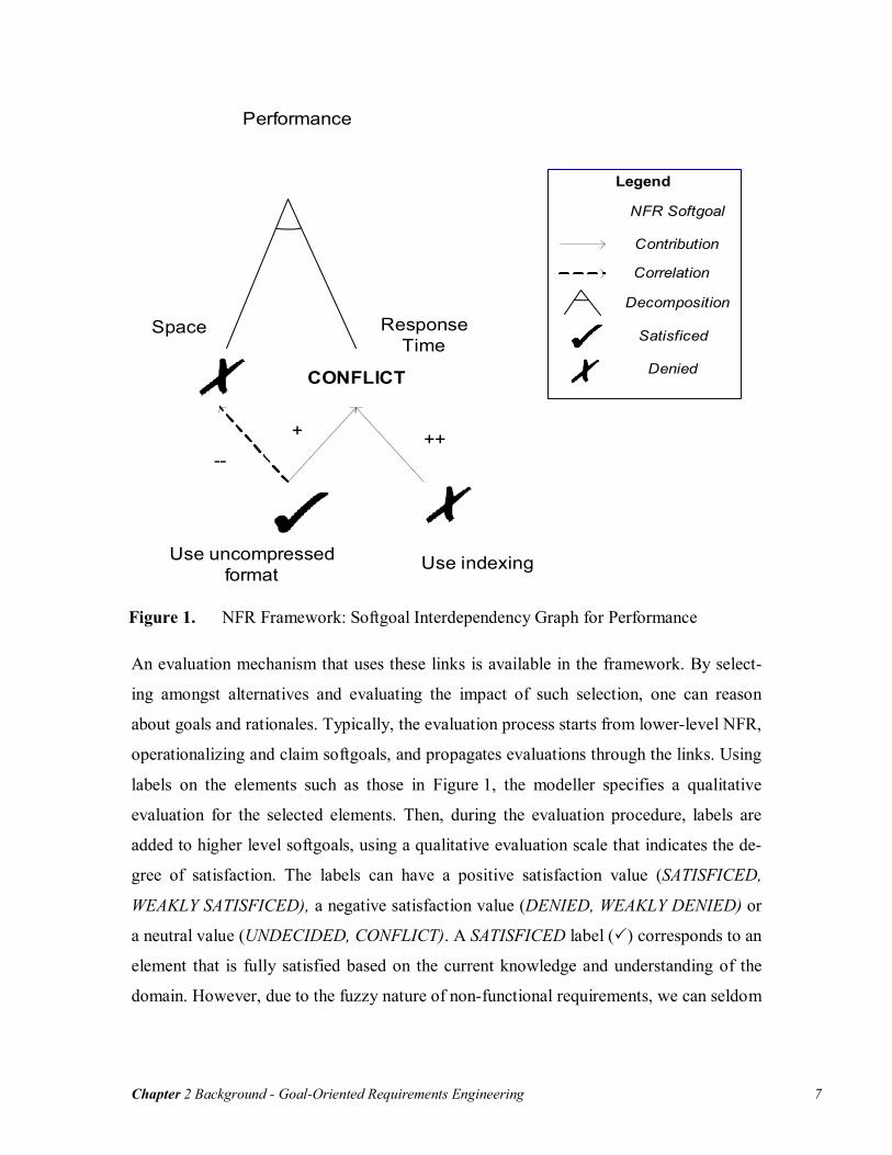
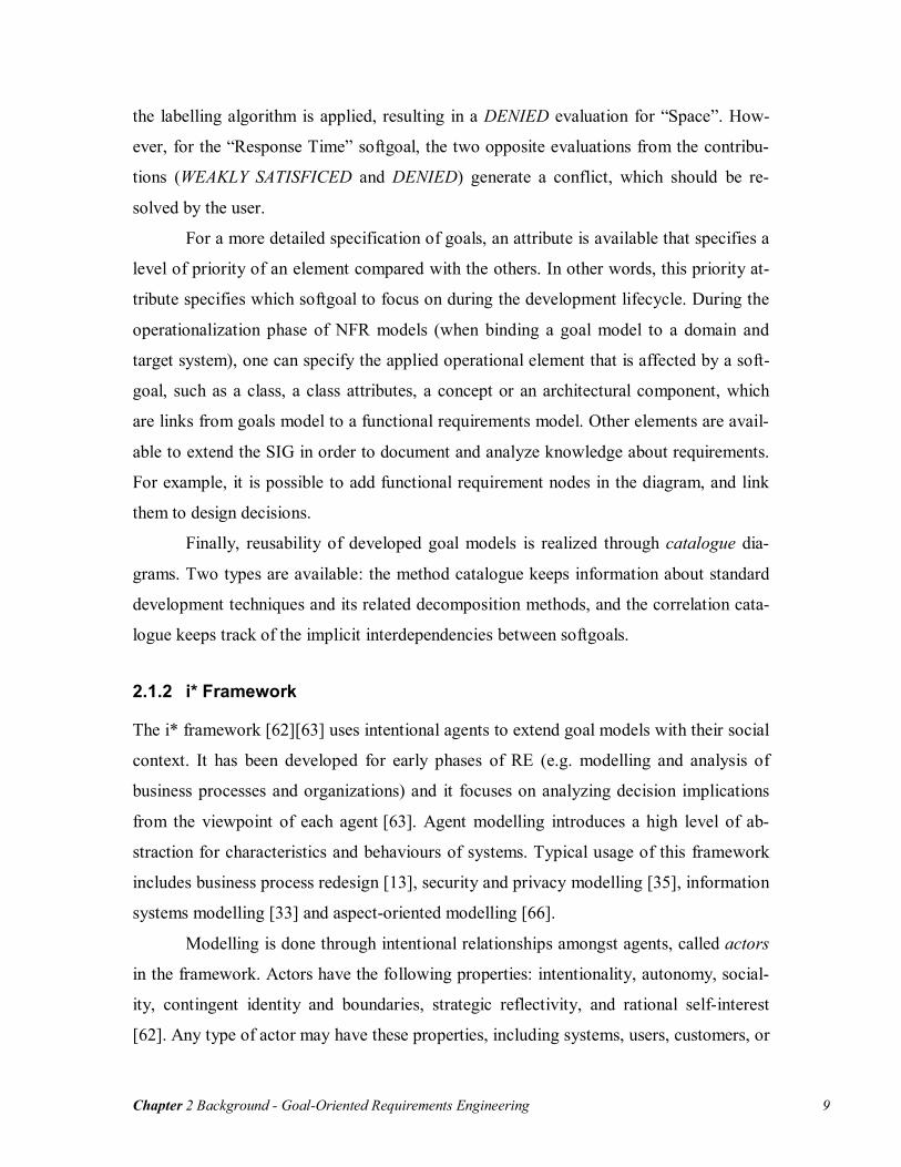
Figure 1 illustrates a Softgoal Interdependency Graph for a performance softgoal
(shown as a cloud). This performance softgoal has been decomposed (AND contribution)
into “Space” and “Response Time”, which means that those two softgoals should be sat-
isficed in order to obtain good performance. “Use indexing” and “Use uncompressed
format” are two operationalizing softgoals, describing solutions that will affect the higher
level softgoals. “Use uncompressed format” BREAKs (--) the space softgoal and HELPs
(+) achieving the “Response Time” softgoal. Furthermore, “Use Indexing” MAKEs (++)
“Response Time”.
Chapter 2 Background - Goal-Oriented Requirements Engineering 7
Performance
Response Time
Space
Use uncompressed format
Use indexing
--
+ ++
CONFLICT
Legend
NFR Softgoal
Contribution
Correlation
Decomposition
Satisficed
Denied
Figure 1. NFR Framework: Softgoal Interdependency Graph for Performance
An evaluation mechanism that uses these links is available in the framework. By select-
ing amongst alternatives and evaluating the impact of such selection, one can reason
about goals and rationales. Typically, the evaluation process starts from lower-level NFR,
operationalizing and claim softgoals, and propagates evaluations through the links. Using
labels on the elements such as those in Figure 1, the modeller specifies a qualitative
evaluation for the selected elements. Then, during the evaluation procedure, labels are
added to higher level softgoals, using a qualitative evaluation scale that indicates the de-
gree of satisfaction. The labels can have a positive satisfaction value (SATISFICED,
WEAKLY SATISFICED), a negative satisfaction value (DENIED, WEAKLY DENIED) or
a neutral value (UNDECIDED, CONFLICT). A SATISFICED label ( ) corresponds to an
element that is fully satisfied based on the current knowledge and understanding of the
domain. However, due to the fuzzy nature of non-functional requirements, we can seldom

Chapter 2 Background - Goal-Oriented Requirements Engineering 8
assume that they are fully satisfied. Further information on the domain could modify
drastically the evaluation of a softgoal1.
The labelling propagation algorithm of the NFR framework is a semi-automatic
procedure, taking into consideration user inputs to assign satisfaction labels to some con-
flicting softgoals. First, it evaluates the impact of each contribution of the softgoals that
have initial satisfaction labels on their respective destination softgoals. Multiple element
contributions are evaluated as typical AND/OR graphs [39], where the source nodes’
lowest satisfaction level is used for AND, and the highest satisfaction level is used for
OR. Single element contributions depend on the contribution type, and are shown in —
Table 1. Note that Help and Some+ contributions have the same impact on parents as
well as Hurt and Some-.
Break Some- Hurt Unknown Help Some+ Make Equal
Satisficed Denied Weakly Denied
Weakly Denied
Undecided Weakly Satisficed
Weakly Satisficed
Satisficed Satisficed
Weakly Satisficed
Weakly Denied
Weakly Denied
Weakly Denied
Undecided Weakly Satisficed
Weakly Satisficed
Weakly Satisficed
Weakly Satisficed
Undecided Undecided Undecided Undecided Undecided Undecided Undecided Undecided Undecided
Weakly Denied
Weakly Satisficed
Weakly Satisficed
Weakly Satisficed
Undecided Weakly Denied
Weakly Denied
Weakly Denied
Weakly Denied
Denied Weakly Satisficed
Weakly Satisficed
Weakly Satisficed
Undecided Weakly Denied
Weakly Denied
Denied Denied
Conflict Conflict Conflict Conflict Undecided Conflict Conflict Conflict Conflict
Table 1 NFR Framework: Impact of Single Element Contributions on the Parents
When only one element contributes to the target softgoal, or when all the contribution
labels are equal, the label of the target softgoal is assigned directly. However, in more
complex situations, such as when two incoming contributions have opposite impacts, the
framework flags the parent node as a conflict and the user must then determine the result
interactively.
In the example of Figure 1, a typical usage of the evaluation algorithm is shown.
The modeller has initially specified the evaluation of the two operational softgoals,
SATISFICED for “Use uncompressed format” and DENIED for “Use Indexing”. Then,
1 In this thesis, satisficed goals and satisfied goals are used interchangeably.
Chapter 2 Background - Goal-Oriented Requirements Engineering 9
the labelling algorithm is applied, resulting in a DENIED evaluation for “Space”. How-
ever, for the “Response Time” softgoal, the two opposite evaluations from the contribu-
tions (WEAKLY SATISFICED and DENIED) generate a conflict, which should be re-
solved by the user.
For a more detailed specification of goals, an attribute is available that specifies a
level of priority of an element compared with the others. In other words, this priority at-
tribute specifies which softgoal to focus on during the development lifecycle. During the
operationalization phase of NFR models (when binding a goal model to a domain and
target system), one can specify the applied operational element that is affected by a soft-
goal, such as a class, a class attributes, a concept or an architectural component, which
are links from goals model to a functional requirements model. Other elements are avail-
able to extend the SIG in order to document and analyze knowledge about requirements.
For example, it is possible to add functional requirement nodes in the diagram, and link
them to design decisions.
Finally, reusability of developed goal models is realized through catalogue dia-
grams. Two types are available: the method catalogue keeps information about standard
development techniques and its related decomposition methods, and the correlation cata-
logue keeps track of the implicit interdependencies between softgoals.
2.1.2 i* Framework
The i* framework [62][63] uses intentional agents to extend goal models with their social
context. It has been developed for early phases of RE (e.g. modelling and analysis of
business processes and organizations) and it focuses on analyzing decision implications
from the viewpoint of each agent [63]. Agent modelling introduces a high level of ab-
straction for characteristics and behaviours of systems. Typical usage of this framework
includes business process redesign [13], security and privacy modelling [35], information
systems modelling [33] and aspect-oriented modelling [66].
Modelling is done through intentional relationships amongst agents, called actors
in the framework. Actors have the following properties: intentionality, autonomy, social-
ity, contingent identity and boundaries, strategic reflectivity, and rational self-interest
[62]. Any type of actor may have these properties, including systems, users, customers, or
Chapter 2 Background - Goal-Oriented Requirements Engineering 10
external organizations. Actors depend on each others for satisfying intentional elements,
which correspond to goals to be achieved, tasks to be performed, and resources to be pro-
vided [64]. Those elements are represented in the Strategic Dependency (SD) model,
which expresses external intentional relationships between the actors, hiding the internal
constructs of the actors involved.
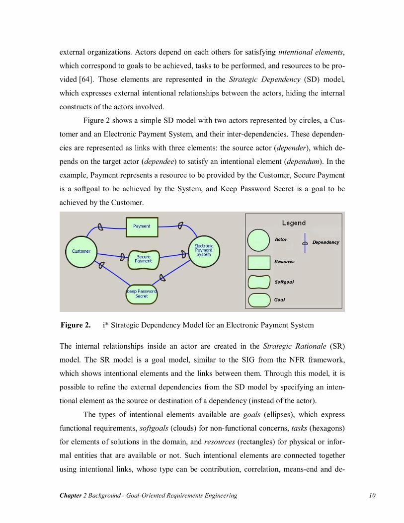
Figure 2 shows a simple SD model with two actors represented by circles, a Cus-
tomer and an Electronic Payment System, and their inter-dependencies. These dependen-
cies are represented as links with three elements: the source actor (depender), which de-
pends on the target actor (dependee) to satisfy an intentional element (dependum). In the
example, Payment represents a resource to be provided by the Customer, Secure Payment
is a softgoal to be achieved by the System, and Keep Password Secret is a goal to be
achieved by the Customer.
Figure 2. i* Strategic Dependency Model for an Electronic Payment System
The internal relationships inside an actor are created in the Strategic Rationale (SR)
model. The SR model is a goal model, similar to the SIG from the NFR framework,
which shows intentional elements and the links between them. Through this model, it is
possible to refine the external dependencies from the SD model by specifying an inten-
tional element as the source or destination of a dependency (instead of the actor).
The types of intentional elements available are goals (ellipses), which express
functional requirements, softgoals (clouds) for non-functional concerns, tasks (hexagons)
for elements of solutions in the domain, and resources (rectangles) for physical or infor-
mal entities that are available or not. Such intentional elements are connected together
using intentional links, whose type can be contribution, correlation, means-end and de-
Chapter 2 Background - Goal-Oriented Requirements Engineering 11
composition. Contribution links can be composed with AND or OR type. Then, a degree
of impact can be assigned to the link: MAKE for positive and sufficient, HELP for posi-
tive but insufficient, SOME+ for unknown positive, SOME- for unknown negative,
HURT for negative but insufficient, BREAK for negative and sufficient, UNKNOWN, and
EQUAL. Furthermore, correlations are available to express side-effects of intentional
elements and use the same impact scale as regular contributions.
To complete the overview, means-end links are available to provide understand-
ing about why an actor would engage in some tasks, pursue a goal, need a resource, or
desire a softgoal [63]. Finally, task decompositions allow modellers to specify what to
achieve in order to perform the decomposed task.
Figure 3. i* Strategic Rationale Model for an Electronic Payment System
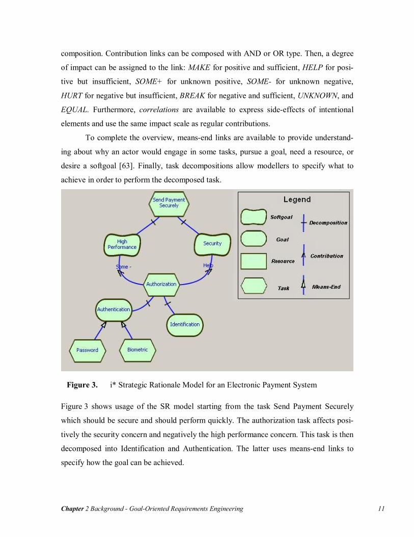
Figure 3 shows usage of the SR model starting from the task Send Payment Securely
which should be secure and should perform quickly. The authorization task affects posi-
tively the security concern and negatively the high performance concern. This task is then
decomposed into Identification and Authentication. The latter uses means-end links to
specify how the goal can be achieved.
Chapter 2 Background - User Requirement Notation (URN) 12
2.2 User Requirement Notation (URN)
The User Requirement Notation (URN) [1][6][23] combines two complementary views,
URN-NFR, the non-functional requirements notation, and URN-FR, the functional re-
quirements notation. It supports development, description and analysis of requirements
for complex, reactive and dynamic systems and is described in the ITU-T Z.150 series of
recommendations [23][25][26].
2.2.1 Goal-oriented Requirement Language
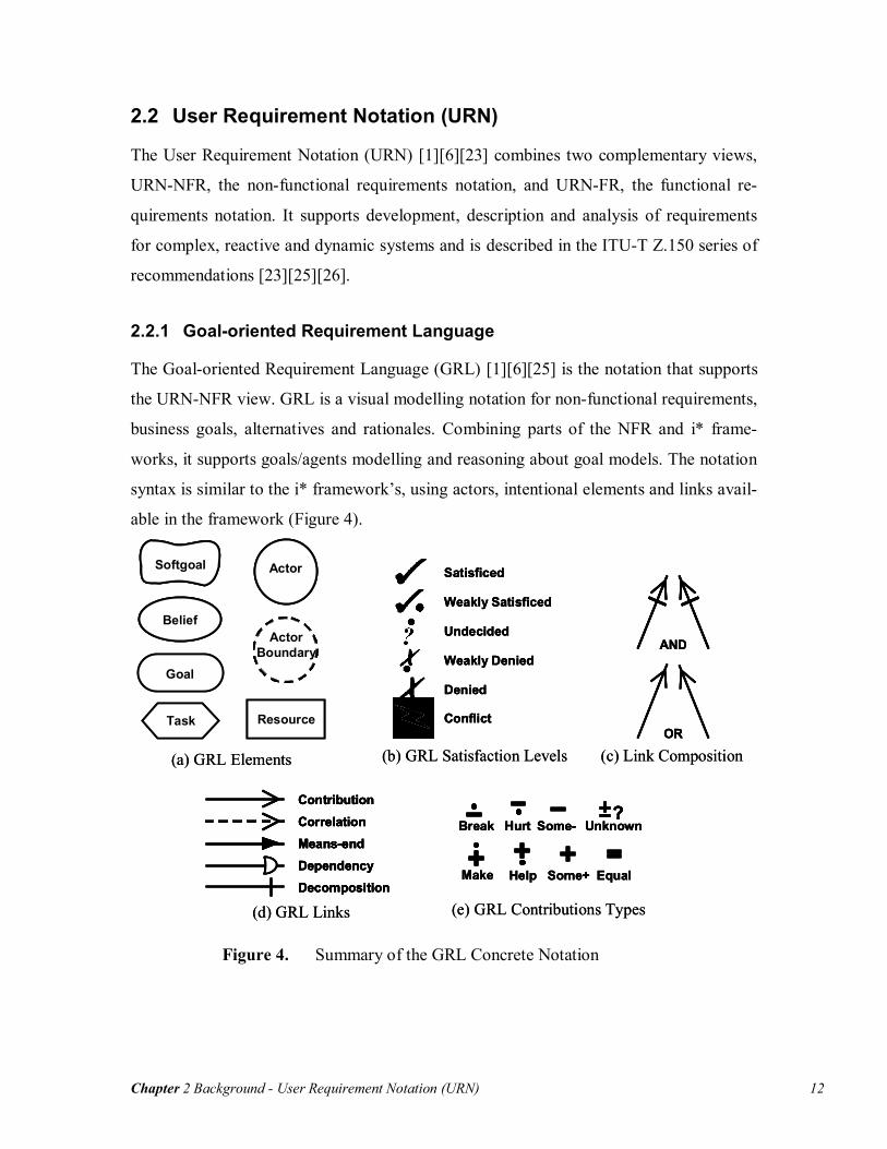
The Goal-oriented Requirement Language (GRL) [1][6][25] is the notation that supports
the URN-NFR view. GRL is a visual modelling notation for non-functional requirements,
business goals, alternatives and rationales. Combining parts of the NFR and i* frame-
works, it supports goals/agents modelling and reasoning about goal models. The notation
syntax is similar to the i* framework’s, using actors, intentional elements and links avail-
able in the framework (Figure 4).
Satisficed
Weakly Satisficed
Undecided
Weakly Denied
Denied
Conflict
(b) GRL Satisfaction Levels
Satisficed
Weakly Satisficed
Undecided
Weakly Denied
Denied
Conflict
Satisficed
Weakly Satisficed
Undecided
Weakly Denied
Denied
Conflict
(b) GRL Satisfaction Levels
Dependency
ContributionCorrelationMeans-end
Decomposition
(d) GRL Links
Dependency
ContributionCorrelationMeans-end
DecompositionDependencyDependency
ContributionContributionCorrelationCorrelationMeans-endMeans-end
DecompositionDecomposition
(d) GRL Links
?Break Hurt Some- Unknown
Make Help Some+ Equal
(e) GRL Contributions Types
?Break Hurt Some- Unknown
Make Help Some+ Equal
??Break Hurt Some- Unknown
Make Help Some+ Equal
(e) GRL Contributions Types
OR
AND
(c) Link CompositionOROR
ANDAND
(c) Link Composition
Goal
Softgoal
Belief
Actor
ActorBoundary
Resource
(a) GRL Elements
Task
Goal
SoftgoalSoftgoal
BeliefBelief
ActorActor
ActorBoundary
ActorBoundary
Resource
(a) GRL Elements
Task
Figure 4. Summary of the GRL Concrete Notation

Chapter 2 Background - User Requirement Notation (URN) 13
GRL supports an evaluation mechanism [1][6][25] similar to NFR framework. It uses
qualitative labels associate to lower-level intentional elements to measure the satisfaction
level of higher-level elements. The qualitative satisfaction labels associated to intentional
elements goes from SATISFICED to DENIED (see Figure 4b). The propagation algorithm
in the draft standard uses links created in the SR model to derive bottom-up satisfaction
levels. As for the NFR framework, the algorithm is semi-automatic as it requires users to
solve generated conflicts.
The GRL evaluation mechanism is applied to the electronic payment system in
Figure 5. In this example, evaluation labels were first provided to elements Password,
Biometric and Identification, and evaluation labels were deduced from them up to Send
Payment Securely, which has a resulting WEAKLY DENIED evaluation.
BiometricPassword
Authorization
SendPaymentSecurely
HighPerformance
Security
IdentificationAuthentication
Figure 5. Evaluation of Candidate Solutions using GRL

Chapter 2 Background - User Requirement Notation (URN) 14
The GRL notation supports belief elements, which provide justifications of the assess-
ments in the model. Beliefs keep track of the rationales in the graphical models. It is also
possible to create contributions from beliefs to GRL links or elements. During evaluation,
those links modify the satisfaction levels of the linked elements/links based on the en-
abled beliefs.
This notation also supports non-intentional elements, which are elements im-
ported from an external model. This element type does not capture the syntax or seman-
tics of the external model, but is used for references to external elements. Non-intentional
elements are defined in the GRL syntax; however, there is no specification of how to deal
with them during analysis and model evolution.
The ITU-T Z.150 recommendation [23] establishes requirements for URN-NFR.
GRL, as the notation for URN-NFR sub-view, meets most of those requirements. The
requirements and an explanation on how GRL deals with them are listed below:
- Expressing tentative, ill-defined and ambiguous requirements: Using the SR
model and softgoals, GRL supports abstract requirements models.
- Clarifying, exploring, and satisficing goals and requirements: GRL links allow
refinements of goals/requirements and alternative explorations.
- Expressing and evaluating measurable goals and NFRs: Support for a qualitative
evaluation process is available. However, there are no proposed quantita-
tive/measurable metrics associated with the goals and NFRs.
- Argumentation: Argumentations are modeled with beliefs associated with corre-
sponding elements in the model.
- Linking high-level business goals to systems requirements: The notation allows
expressing high-level business goals and system requirements. GRL links are
used to connect high-level goals to lower level system requirements. However,
there is no formal way to link GRL elements to other form of requirements, such
as textual requirements or scenarios.
- Multiple stakeholders, conflict resolution and negotiation support: SD models
stakeholders and their dependencies. Through the intentional element links, re-
quirements engineers can analyse the model in terms of stakeholder negotiation

Chapter 2 Background - User Requirement Notation (URN) 15
and conflict resolution. However, there is no technique proposed in the draft stan-
dard to realize this objective.
- General and stakeholder’s requirements prioritisation: Intentional elements sup-
port attributes for priority and criticality amongst elements. However, those at-
tributes does not have any influence in the evaluation process.
- Requirements creep, churn, and other evolutionary forces: The contribution types
and the GRL satisfaction levels are useful to deal with requirements evolution.
These elements help the requirements engineer to evaluate the impact of new or
modified requirements on other requirements.
- Integrated treatment of functional and non-functional requirements: GRL can
deal with non-functional requirements using softgoals and with functional re-
quirements using goals and tasks. It is also possible to express functional re-
quirement alternatives using those elements and GRL links.
- Multiple rounds of commitment: Each new round of decision-making is based on
previous rounds. Beliefs can help keeping information about multiple rounds of
commitments. However, these requirements are not well supported because the
notation as no mechanism to distinguish information coming from preceding
commitment rounds, which can be supported by combining the notation with a
Requirements Management System.
- Life-cycle support: It is supported through the refinement mechanism (GRL
links).
- Traceability: The non-intentional elements introduced support for traceability of
requirements with other notation. However, usage of this feature in the notation is
not well defined in the standard.
- Ease of use and precision: The notation uses concepts from widely used
goals/agents notation (NFR framework/i*), which helps understanding the nota-
tion.
- Modularity: Not supported.
- Reusable requirements: Not supported.

Chapter 2 Background - User Requirement Notation (URN) 16
2.2.2 Use Case Map Notation
Use Case Maps (UCM) [1] [6] [26] is a scenarios-based notation for gathering functional
requirements such as operational or architectural requirements. Unlike use cases or others
scenarios notations such as UML 2.0 activity diagrams, UCM supports dynamic refine-
ment at the behavioural and structural level. Furthermore, it offers an integrated view of
scenarios over paths along abstract components, which allow high-level architectural rea-
soning. Furthermore, the dynamic syntax of the notation has proven to be useful in other
domains such as performance modelling [69], test generation [7] and reverse-
engineering [20].
Figure 6. UCM Model of an Evaluation System
In UCM models, scenarios are sequences of responsibilities (X’s) corresponding to ac-
tivities, tasks or functions perform by a system, and disposed on paths (curved lines) that
describe the causality flows in maps. Responsibilities can be bound to components, which
are functional or logical entities. Scenarios progress through paths from start points
(filled circle) to end points (bars). The above example (Figure 6) shows typical elements
used in UCM model. A stub (diamond) is used to include sub-maps. These sub-maps,
called plug-ins, allow the hierarchical structuring of the model and provide a way to en-

Chapter 2 Background - User Requirement Notation (URN) 17
capsulate and reuse given aspects of the model. Finally, dynamic stubs are available to
specify alternative maps at a given location.
The UCM syntax also includes constructs for alternative and parallel processing.
AND-Forks split a path into concurrent paths while OR-Forks specify alternatives, based
on the conditions for each exiting path. In addition, AND-Joins and OR-Joins are avail-
able to synchronize or merge multiple paths in the model (Figure 7).
……
……
[C1][C2]
[C3]
OR-Fork& GuardingConditions
……
……
OR-Join
……
…… …
…
……
AND-JoinAND-Fork
(b) UCM Forks and Joins
……
……
[C1][C2]
[C3]
OR-Fork& GuardingConditions
……
……
OR-Join
……
……
[C1][C2]
[C3]…
…
……
[C1][C2]
[C3]
OR-Fork& GuardingConditions
……
…… ……
……
OR-Join
……
…… …
…
……
AND-JoinAND-Fork…
…
…………
…… …
…
…… ……
……
AND-JoinAND-Fork
(b) UCM Forks and Joins
StartPoint
EndPoint
Path
… …… … Responsibility
Direction Arrow
… … Timestamp PointFailure Point… …Shared Responsibility… …
(a) UCM Path Elements
StartPoint
EndPoint
Path
… …… …… …… …… … Responsibility
Direction Arrow
… …… …… … Timestamp PointFailure Point… …… …… …Shared Responsibility… …… …… …
(a) UCM Path Elements
(c) UCM (Generic) Component(c) UCM (Generic) Component
Waiting Place
TriggerPath (asynchronous)
WaitingPath
ContinuationPath
Timer
TimerRelease(synchronous)
WaitingPath
ContinuationPath
Timeout Path
(e) UCM Waiting Places and Timers
Waiting Place
TriggerPath (asynchronous)
WaitingPath
ContinuationPath
Waiting Place
TriggerPath (asynchronous)
WaitingPath
ContinuationPath
Timer
TimerRelease(synchronous)
WaitingPath
ContinuationPath
Timeout PathTimer
TimerRelease(synchronous)
WaitingPath
ContinuationPath
Timeout Path
(e) UCM Waiting Places and Timers
… …IN1 OUT1 Static Stub & Segments ID
Dynamic StubIN1 OUT1… …S{IN1} E{OUT1}
(d) UCM Stubs and Plug-insPlug-in Map
… …IN1 OUT1… …… …IN1 OUT1 Static Stub & Segments ID
Dynamic StubIN1 OUT1… …IN1 OUT1… …… …S{IN1} E{OUT1}S{IN1} E{OUT1}
(d) UCM Stubs and Plug-insPlug-in Map
Figure 7. Summary of a Subset of the UCM Concrete Notation
UCM is a notation that attempts to fill the gap between requirements and architectural
modelling [6]. To support this intent, various transformations have been developed to
lower-level notations such as Message Sequence Chart (MSC) [2], UML sequence dia-
grams [4] and Layered Queuing Networks (LQN) [45].

Chapter 2 Background - User Requirement Notation (URN) 18
2.2.3 Combining Goals and Scenarios
URN supports semi-formal modelling and analysis of requirements by combining goals
and scenarios. URN combines two notations, developed in isolation, to find, manage,
evolve, and document functional and non-functional requirements through the system
development life-cycle. Even if GRL and UCM can be used as standalone notations, us-
ing them together allows discovering and refining requirements through goals and depict-
ing their elaboration and realization into architectural models through scenarios. Figure 8,
taken from [6], shows how URN relates to ITU-T languages and UML. However, despite
a few publications where integrated URN models are used, there is no concrete definition
of how best to link the two sub-views.
Figure 8. URN as a Missing Piece of the Modelling Puzzle
The URN syntax allows the notation to be usable to model various domains. For exam-
ple, it has been used for business processes modelling [6][59]. URN can be used to model
current and future business goals, their interactions, and the corresponding stakeholders
with GRL. Then, business processes are modelled in UCM using identified agents in
GRL as components. The dynamic constructs (e.g. OR-Forks and dynamic stubs) allow
specifying alternatives and modelling current and future business processes. In this con-
??MSC, UML Use
Case Diagram & Activity Diagram
??????MSC, UML Use
Case Diagram & Activity Diagram
InformalRequirements,
Textual Use Cases
InformalRequirements,
Textual Use CasesStructural Diagrams
SDL, eODL, or UML class, object,
component, & deployment
diagrams
Structural Diagrams
SDL, eODL, or UML class, object,
component, & deployment
diagrams
Testing and Performance Languages
TTCN, LQN, ...
Testing and Performance Languages
TTCN, LQN, ...
Behavioral DiagramsMSC/SDL, or UML
sequence, collabor., & statechart diagrams
Behavioral DiagramsMSC/SDL, or UML
sequence, collabor., & statechart diagrams
URN-FR / UCMsSuperimpose visually system level behavioronto structures of abstract components. Can
replace UML use case & deployment diagams.
URN-FR / UCMsSuperimpose visually system level behavioronto structures of abstract components. Can
replace UML use case & deployment diagams.
URN-FR / UCMsSuperimpose visually system level behavioronto structures of abstract components. Can
replace UML use case & deployment diagams.
URN-NFR/GRLGoals, non-functionalrequirements, alterna-
tives, rationales
URN-NFR/GRLGoals, non-functionalrequirements, alterna-
tives, rationales
Chapter 2 Background - User Requirement Notation (URN) 19
text, UCM models explain what are the activities related to business goals, who is in-
volved, where they are performed and when they should be performed [59].
Liu and Yu proposed a modelling methodology to integrate the notations [34].
They focus on answering “why” questions with goals and “what” and “how” with scenar-
ios. Using an iterative, goal-scenario modelling process, goal refinement helps to make
architectural design decisions (involving tasks) that can be ported to UCM models. Path
and scenario refinements also enable the modeller to question the completeness and rele-
vance of the goal model. This process is iterative until no more refinement can be found
in the design rationales or architectural design models.
Even if the above methodology integrates GRL and UCM, no traceability links
are suggested between the two views. The Z.150 standard [23] emphasizes the necessity
of internal links (between GRL and UCM) and external links (to other models). External
traceability links are defined as links to textual requirement documents, external require-
ment objects, and other models used in the development process. With those links, it is
possible to perform impact analysis based on changes in one of the models, as suggested
in Model-Driven Development (MDD).
Combination of goals and scenarios is an approach to requirement modelling
study in other approaches. Crews-L’Ecritoire [46] proposed a methodology to guide re-
quirements elicitation using Requirement Chunks, which are pairs of goal and scenario. It
defines a bidirectional goal-scenario coupling, where the definition of one of those ele-
ments helps in the elicitation of the others. Goals and scenarios are expressed as textual
elements where goals are expressed as clauses that have a verb and different parameters
and where scenarios are expressed as combinations of actions. This approach helps to dis-
cover goals and scenarios in early requirements phases. However, the strict definition of
requirement chunks and the necessity to link a goal to a scenario cause this approach to
be valid only for functional requirements.
Another approach consist in linking NFR Framework element to UML [51][52]
using a UML profile. This profile defines SIG diagram in UML, and extends UML Use
Case Model to include softgoals. Then, links are created between softgoals and use cases,
or between softgoals and actors. This approach is interesting to extend UML, but links do

Chapter 2 Background - URN-Related Tools 20
not help defining new goals or use cases needed in early requirements. Also, the created
relationships are unidirectional, from softgoal to Use Case elements.
2.3 URN-Related Tools
At the time this work was initiated, there was no tool supporting the integrated URN no-
tation. However, there are tools for UCM models and goal models (with GRL or similar
to it). This section gives an overview of these tools.
2.3.1 Goal-oriented Requirement Engineering Tools
OME/OpenOME The Organization Modelling Environment (OME) [42] as well as it newer open source
counterpart, OpenOME [61], support multiple goal and agent languages, including GRL,
i* and NFR. OME is a Java standalone application whereas OpenOME can be integrated
to multiple development environments (Eclipse, Protégé, and Visio). Figure 9 shows an
i* strategic dependencies model in OME.
Figure 9. Strategic Dependencies Model in OME

Chapter 2 Background - URN-Related Tools 21
Developed using a Model-View-Controller architecture, this tool supports notation exten-
sions through the OME meta-framework. This meta-framework describes object types
supported, such as nodes, links and expandable objects. Expandable objects are bounda-
ries objects which support elements binding (such as i*/GRL actors).
Tool plug-ins handle model manipulations and views. The framework description
is implemented using Telos files, which are set of rules that instantiate OME meta-
framework elements for a specific notation. These framework descriptions are loaded by
users. Moreover, the current tool architecture does not support multiple model views.
The GRL implementation supports the elements, links and evaluation algorithm
presented in the preceding section. However, OME does not support embedded actors
(actors inside actors), and it is not possible to create multiple GRL diagrams in the same
model. Furthermore, the tool is difficult to use and has serious performance problems.
Developing models with the tool is complex. Complexity increases and reliability de-
creases with the size of the model.
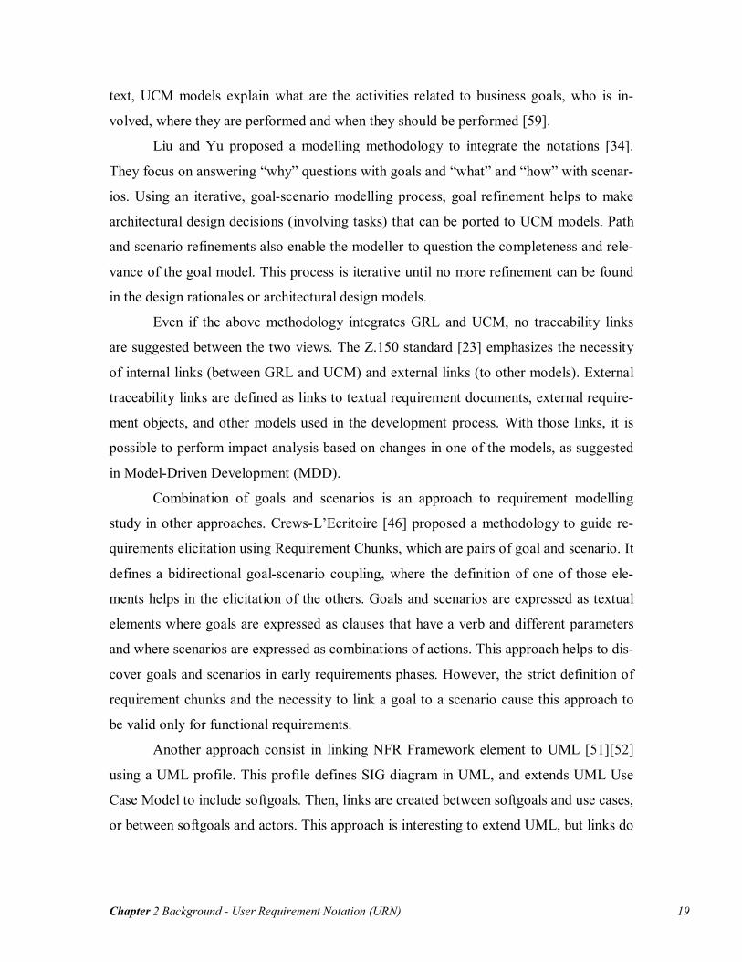
SanDriLa SanDriLa [48] implements add-in for ITU-T languages (URN, SDL, MSC, TTCN) for
Microsoft Visio. The current release (4.0) supports GRL, as shown in Figure 10. This ap-
plication is a template that allows drawing GRL elements and links in a diagram. How-
ever, this allows for the drawing of syntactically incorrect diagrams and it does not in-
clude any support for model analysis.
Chapter 2 Background - URN-Related Tools 22
Figure 10. GRL Modelling with SanDrila for MS Visio
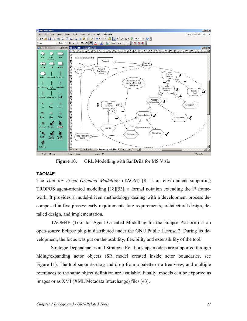
TAOM4E The Tool for Agent Oriented Modelling (TAOM) [8] is an environment supporting
TROPOS agent-oriented modelling [18][53], a formal notation extending the i* frame-
work. It provides a model-driven methodology dealing with a development process de-
composed in five phases: early requirements, late requirements, architectural design, de-
tailed design, and implementation.
TAOM4E (Tool for Agent Oriented Modelling for the Eclipse Platform) is an
open-source Eclipse plug-in distributed under the GNU Public License 2. During its de-
velopment, the focus was put on the usability, flexibility and extensibility of the tool.
Strategic Dependencies and Strategic Relationships models are supported through
hiding/expanding actor objects (SR model created inside actor boundaries, see
Figure 11). The tool supports drag and drop from a palette or a tree view, and multiple
references to the same object definition are available. Finally, models can be exported as
images or as XMI (XML Metadata Interchange) files [43].

Chapter 2 Background - URN-Related Tools 23
Figure 11. Goal Modelling with the TAOM4E Tool
The main limitation of TOAM4E is the absence of analysis features. The tool only pro-
vides an editor interface. However, TAOM4E supports extensions that could be use to
implement analysis mechanisms.
GRTool GRTool (Goal Reasoning Tool) [19] supports goal model editing and analysis through
forward and backward reasoning algorithms [17][18][49]. Model editing is realized with
three types of elements: goals, top goals and events. Semantically, there is no difference
between goals and top goals other than distinguishing higher-level goals that should be
evaluated during the analysis phase. Events correspond to operational elements, similar to
tasks in GRL. Available links are contributions and AND/OR compositions. The contri-
butions can take one of the two positive or negatives labels, depending on whether the
contributor satisfies (or denies) partially or completely the contributee. A simple example
of model developed in GRTool is shown in Figure 12.
This tool innovates with reasoning techniques that use qualitative or quantitative
measures, and users can switch back and forth from one type of measure to the other. The
following example illustrates how the reasoning technique is applied.

Chapter 2 Background - URN-Related Tools 24
Figure 12. Goal Modelling with GRTool
Suppose a goal G. There are four possible qualitative predicates for goal G: FS(G),
FD(G), PS(G) and PD(G). They correspond to full evidence that goal G is satisfied (or
denied) or partial evidence that goal G is satisfied (or denied). Qualitative evaluation is
made based on the rules specified in Table 22.
The algorithm proposed in [18] has two labels associated with each node: one for
the satisfaction level and the other for denial level. Users assign an initial set of labels to
nodes and propagation rules are applied based on the relations linking the various nodes.
Cycles in the diagram are supported through an algorithm that stops when label updates
are no longer possible (i.e., the set of current labels is equal to the previous set of labels),
or when a maximum number of iterations has been executed. Node G is considered in
weak conflict if its two labels are PS(G) and PD(G), FS(G) and PD(G), or PS(G) and
FD(G). G is considered in strong conflict when the labels are FS(G) and FD(G).
2 Note that propagation rules are symmetric (applicable for denied labels)

Chapter 2 Background - URN-Related Tools 25
Goal – Goal Relation Invariant and Relation Axiom
G: FS(G) → PS(G) FD(G) →PD(G)
(G2,G3) AND G1:
(FS(G2) ∧ FS(G3)) → FS(G1) (PS(G2) ∧ PS(G3)) → PS(G1) FD(G2) → FD(G1), FD(G3) → FD(G1) PD(G2) → PD(G1), PD(G3) → PD(G1)
G2 +s G1: FS(G2) → PS(G1) PS(G2) → PS(G1)
G2 -s G1: FS(G2) → PD(G1) PS(G2) → PD(G1)
G2 ++s G1: FS(G2) → FS(G1) PS(G2) → PS(G1)
G2 --s G1: FS(G2) → FD(G1) PS(G2) → PD(G1)
Table 2 Propagation Rules for the GRTool Qualitative Reasoning Algorithm
To use quantitative values in the algorithm, qualitative labels are converted into values
between 0 and 1: FS(G) and FD(G) to 1, PS(G) and PD(G) to 0.5. These values can then
be fine-tuned by the users, with the definition that partially satisfied/denied corresponds
to a numerical value between 0 and 1 inclusively. Furthermore, contribution labels are
also converted into numerical value between 0 and 1 and can be fine-tuned by the users.
Once the conversion is completed, it is possible to apply the propagation algorithm using
the same rules presented before.
Finally, another algorithm is available for top-down propagation. Based on an ini-
tial set of labels for the top goals, this algorithm is applied to determine the minimal val-
ues necessary for the satisfied/denied labels of the leaf nodes in the graph.
We can observe several strengths and weaknesses of existing goal-oriented tools,
as well as the lack of integration with scenario notations (as proposed in URN) and other
general requirements in a RMS. Table 3 shows how these goal-oriented tools meet the
URN-NFR requirements described in section 2.2.1.

Chapter 2 Background - URN-Related Tools 26
URN-NFR Requirements OME/OpenOME GRTool TAOM4E SanDriLa
Expressing tentative, ill-defined and am-
biguous requirements
++ -- ++ ++
Clarifying, exploring, and satisficing goals
and requirements
++ + ++ ++
Expressing and evaluating measurable
goals and NFRs
+ ++ -- --
Argumentation + -- + --
Linking high-level business goals to sys-
tems requirements
- -- - --
Multiple stakeholders, conflict resolution
and negotiation support
+ -- + +
General and stakeholder’s requirements
prioritisation
-- + + --
Requirements creep, churn, and other
evolutionary forces
++ ++ -- --
Integrated treatment of functional and
non-functional requirements
+ + + +
Multiple rounds of commitment - -- - --
Life-cycle support - - - --
Traceability -- -- -- --
Ease of use and precision - - + +
Modularity -- -- -- --
Reusable Requirements -- -- -- --
Table 3 Comparison of Goal-Oriented Tools Based on URN-NFR Requirements
2.3.2 Use Case Maps Tools
The UCM notation is supported by UCMNav (for UCM Navigator) [36][58], and re-
cently by the newer jUCMNav (for Java UCM Navigator) [28][30]. UCMNav, in devel-
opment since 1997, supports the editing and analysis of UCM models as well as trans-
formations to others notations. The tool however presents serious usability issues, caused
by a non-standard, counter-intuitive user interface. Also, UCMNav requires the presence
of an X Window server, which results in difficult deployment on Microsoft Windows
systems. Finally, the tool is hard to maintain because of a software architecture that has
dissolved over time and because of a lack of documentation.

Chapter 2 Background - URN-Related Tools 27
The more recent jUCMNav tool addresses many of these problems by providing
an Eclipse-based implementation. Eclipse is a multi-platform environment, developed in
Java, which supports extensions via a plug-in mechanism. This mechanism allows easy
deployment, which consists in uncompressing a file in a directory, or automatically in-
stalling the plug-in through an on-line update site.
jUCMNav has been developed using two complementary plug-ins: the Eclipse
Modeling Framework (EMF) [14] and the Graphical Editing Framework (GEF) [15].
EMF proposes a meta-meta model to manage models and auto-generate Java code from
UML class diagrams. The jUCMNav authors developed an EMF-based metamodel for
the UCM notation, which describes the abstract implementation syntax of the notation.
For visualizing and editing models, GEF offers many features that facilitate the develop-
ment of user interfaces compliant with the Eclipse user interface standard. Using those
two frameworks together in combination with a notification mechanism, jUCMNav was
developed based on the Model-View-Controller (MVC) design pattern.
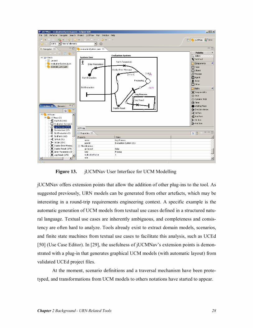
jUCMNav is an open source application available under the Eclipse Public Li-
cense (EPL) 1.0. The first version of the tool [28], released in July 2005, included three
major views (see Figure 13): the graphical editor with a tool palette to add and manage
elements in the models, the properties view to manage attributes of elements, and a
graphical/hierarchical outline. Furthermore, a custom element view is available, which
lists elements in the models and their descriptions. Finally, standard Eclipse views such
as navigator and resource are used to manage the models like any other Eclipse-based
application.
Compared with UCMNav, jUCMNav does not yet support all of the UCM con-
structs. The core path elements are supported, such as start points, end points, responsi-
bilities, stubs, waiting places, timers, and forks/joins, as well as various component types,
like actors, agents, processes and teams. Element and component binding to parent com-
ponents is also supported. Furthermore, jUCMNav only allows the creation of syntacti-
cally valid UCM models, and verifies potential problems such as implicit loops. The tool
also supports static and dynamic stubs, with plug-in bindings.
Chapter 2 Background - URN-Related Tools 28
Figure 13. jUCMNav User Interface for UCM Modelling
jUCMNav offers extension points that allow the addition of other plug-ins to the tool. As
suggested previously, URN models can be generated from other artefacts, which may be
interesting in a round-trip requirements engineering context. A specific example is the
automatic generation of UCM models from textual use cases defined in a structured natu-
ral language. Textual use cases are inherently ambiguous, and completeness and consis-
tency are often hard to analyze. Tools already exist to extract domain models, scenarios,
and finite state machines from textual use cases to facilitate this analysis, such as UCEd
[50] (Use Case Editor). In [29], the usefulness of jUCMNav’s extension points is demon-
strated with a plug-in that generates graphical UCM models (with automatic layout) from
validated UCEd project files.
At the moment, scenario definitions and a traversal mechanism have been proto-
typed, and transformations from UCM models to others notations have started to appear.

Chapter 2 Background - Requirements Management System 29
However, the current design has prioritized maintainability and extensibility, de-
veloper documentation is abundant, and the system’s core functionality is covered by re-
gression tests. This greatly contrasts with it precursor.
Finally, developed in parallel with jUCMNav, the ArchSynch tool [9] is an
Eclipse plug-in for UCM modelling created to deal with inconsistencies between archi-
tectural documentation and implementation.
2.4 Requirements Management System
Requirements Management Systems (RMS) are software applications used to capture,
manage, and analyse evolving requirements. They support functionalities such as trace-
ability, impact analysis, and requirements change management. This section presents one
of the most popular RMS, Telelogic DOORS3, and it extension mechanism. Then, the
integration of UCM models in DOORS is introduced.
2.4.1 Telelogic DOORS
Telelogic DOORS [55] is a requirements management tool that uses a client-server archi-
tecture and a revision control system to manage text objects, diagrams and document
specifying requirements. In addition, it supports user-defined types of links between ob-
jects.
DOORS uses particular concepts for its structure. First, DOORS databases are
used to store the data. The client application connects to a specific database, one at a
time. Then, folders are used to structure the data. Finally, projects correspond to work-
spaces for requirements data. Through those concepts, users can create a hierarchical
structure of folders and projects. Within a project, formal modules are containers of in-
formation such as textual requirements or graphics. Normally, a module is displayed as a
standard document where numerical identifiers are used to distinguish objects. Objects
are the basic unit of data. An object could be text, an image, or a heading (for an object
containing other objects). Finally, characteristics about objects are stored in attributes.
Users can define their own attributes but common attributes are also available by default. 3 For several years, DOORS has been the RMS market leader according to reports from Gartner, META Group, Standish Group and Yphise.

Chapter 2 Background - Requirements Management System 30
Traceability is supported in DOORS through links. Links are relationships be-
tween source and target objects. These links are used for traceability analysis and are de-
fined and instantiated in link modules. If linked source or target objects are modified, the
application provides feedback by triggering suspect links. Those links suggest that the
linked objects need inspection (modification on one end of a link may impact the other
end). Once suspect links have been inspected, users should clear them. The requirements
traceability analysis is driven by the baselines, which correspond to versions of the re-
quirements from where to start analysis. Using baselines, it is possible to work on concur-
rent versions of the requirements.
DOORS supports an application-specific scripting language named DXL
(DOORS eXtension Language) [56]. Many key features in DOORS were developed us-
ing DXL, such as file format importers/exporters, impact and traceability analysis, and
inter-module linking tools. DXL uses a C-like syntax and allows extending and customiz-
ing DOORS. For the end users, those extensions appear as modifications to the graphical
interface.
Figure 14. UCM Model in Telelogic DOORS

Chapter 2 Background - Requirements Management System 31
2.4.2 Importing UCM Models into DOORS
As suggested before, UCM models can be used to complement textual requirements.
However, with the evolution of requirements over time, synchronization between UCM
models and the textual requirements is difficult to maintain. An approach was developed
by Jiang to support traceability between UCMs and textual requirements using
DOORS [27][37].
The approach consists in using a UCM tool (UCMNav or jUCMNav) to maintain
the UCM model, and import it into DOORS to keep the synchronization with textual re-
quirements. The importing mechanism in DOORS is managed using DXL scripts, which
provide an Application Programming Interface (API) for UCMs. The approach is illus-
trated in Figure 15.
Figure 15. Integrating UCM and DOORS
The process starts by generating a DXL script from a UCM tool. The export from UCM
to DXL is realized by traversing the UCM model and generating corresponding calls to
the UCM DXL library. Then, the generated script is run in DOORS. Auto-completion of
links is used to build the link instances between UCM elements. Once the model is im-
ported, users link the various UCM model elements with textual requirements and modify
any of the DOORS objects. A report is generated by the DXL library that flags the UCM
elements that could be affected by changes to linked objects. Then, it is the responsibility
of the UCM users to synchronize the UCM models with the modified textual require-
ments. Re-importing a new version of the UCM model may also trigger suspect links, and

Chapter 2 Background - Chapter Summary 32
customized views are provided to emphasize the places where attention is required. Syn-
chronization can hence be achieved as the UCM model and the textual requirements
evolve.
Importing a UCM model in DOORS automatically generates various formal and
link modules. The formal modules are responsibilities, devices, components, maps and
scenarios. Each of these modules includes their corresponding UCM elements, which are
identified using unique identifiers from the UCM model. For example, the maps module
contains several sections, one for each map (Figure 14). Maps are exported as images and
have child elements, which are responsibility references, component references and stubs.
Once each formal module has been created, the internal links are created (between UCM
elements). These links defined model-based relations between elements. They could be
between elements in the same formal modules, such as maps and their elements in the
maps module, or between elements in two formal modules, such as responsibility refer-
ences in the maps module and responsibility definitions in responsibilities module. Fi-
nally, external links are created manually, between UCM elements and DOORS objects
(requirements). Those links are the main component of traceability analysis between the
textual requirements and UCMs.
2.5 Chapter Summary
This chapter introduced concepts used in this thesis. First, frameworks with goals and
agents as central modelling constructs have been presented in section 2.1. These frame-
works were the inspiration of the Goal-oriented Requirements Language (GRL), a sub-
view of the User Requirements Notation (URN), which was presented in section 2.2.
Then, an overview of tools available for goal notations for URN’s scenario notation was
provided in section 2.3, followed by an existing approach supporting the integration of
UCM models with textual requirements in DOORS (section 2.4).
The next chapter will explain how an integrated tool for URN can be developed.

Chapter 3 Integrated Tool Support for URN - Requirements and Rationale for an Integrated URN Tool 33
Chapter 3 Integrated Tool Support for URN
This chapter presents a new version of jUCMNav which integrates both GRL and UCM.
In section 3.1, the high-level requirements and rationales that drive the development of
the tool are explained. Then, section 3.2 provides an abstract and an implementation
metamodel for URN. An overview of the development and architecture of the tool and
the basic editing features is presented in section 3.3, followed by GRL catalogues, a new
feature supporting the reusability of GRL models (section 3.4). Finally, a case study that
uses the tool is introduced.
3.1 Requirements and Rationale for an Integrated URN Tool
The main goal of this thesis consists of integrating goal and scenario modelling using
URN. An integrated tool will allow editing and analyzing functional and non-functional
requirements together. In addition, we want to develop a tool that will satisfy most of the
URN-NFR requirements.
Our main goal of integrating goals and scenarios can be decomposed into sub-
goals, as shown in Figure 16. URN models, as models used to fill the gap between re-
quirements and architectural models, shall support analyzing the architectural impact of
changes in requirements. This will be possible by linking URN and external require-
ments. It is considered a goal that shall be satisfied to achieve the integration of URN.
A common metamodel for GRL and UCM is also required. This goal has a posi-
tive contribution to the Integrated Tool Support goal, by allowing modellers to use all
elements specified in URN. For this concern to be satisfied, it is required that the tool al-
lows one to create and modify the URN model (Editing Goal and Scenario Models goal).
In addition, the tool should be usable, should generate models that are graphically com-
plete, and should allow the reuse of models. Finally, it is also required to have analysis
mechanisms for goals and scenarios.

Chapter 3 Integrated Tool Support for URN - Requirements and Rationale for an Integrated URN Tool 34
Figure 16. High-Level Goals for an Integrated URN Tool
Figure 17. Implementation Solutions
As shown in Figure 17, several implementation solutions were evaluated to support an
integrated URN tool. The alternatives are divided into two categories: implementing a
new tool from scratch, or extending an existing tool. In [5], we evaluated the option of
creating a new tool with technologies for easier and faster development of Domain-
Specific Modeling Languages (DSML): Generic Modeling Environment (GME) [23],
Xactium’s XML Mosaic [60], Telelogic Tau G2 [54], Rational Software Architect [22]

Chapter 3 Integrated Tool Support for URN - Requirements and Rationale for an Integrated URN Tool 35
and a combination of EMF and GEF in Eclipse. We developed editors for a subset of
GRL using each technology. Then, we did an evaluation of the technologies based on cri-
teria such as graphical completeness, editor usability, effort needed, language evolution,
integration with other languages, and analysis capabilities. Our results demonstrated that
for simple prototypes, GME is an interesting option to consider. However, even if Eclipse
plug-ins with EMF and GEF is the solution that needs the most effort, it is the only
evaluated framework with the required capabilities for developing an industrial-strength
editor.
We also evaluated implementing our tool by extending URN-related tools de-
scribed in chapter 2. Among the five tools evaluated, four are used to edit and analyze
goals and one for scenarios. In addition, OpenOME, TAOM4E and jUCMNav are
Eclipse plug-ins. Common
Metamodel Graphical Completeness
Usability Reusing Developed Models
Goal and Scenario Analysis
Links with External Requirements
New Tools GME Make Some
Negative Some
Negative Some
Positive Some
Positive Hurt
XMF Mosaic Make Break Hurt Help Help Hurt Rational Soft-ware Architect
Make Break Hurt Some Negative
Some Negative
Help
Telelogic Tau G2
Make Hurt Some Negative
Some Positive
Some Positive
Help
Existing Tools GRTool Break Break Some
Negative Unknown Some
Positive Hurt
OME/OpenOME Make Break Some Negative
Help Some Positive
Unknown
TAOM4E Make Some Positive
Help Unknown Unknown Unknown
SanDriLa Break Break Some Negative
Hurt Hurt Hurt
jUCMNav 1.0 Help Help Help Some Positive
Help Help
Table 4 Contributions of the Tools on High-Level Goals
Each implementation solution contributes to the high-level goals, shown in Table 4. For
goals such as Graphical Completeness, only two solutions have positive contributions:
TAOM4E and jUCMNav. However, the only solution that contributes positively to all
our requirements is jUCMNav. In addition, this is the only tool that has been designed to
support URN from the start. OME supports GRL, but its implementation targets many
types of goal models. In addition, there is no solution in the new tools category that could

Chapter 3 Integrated Tool Support for URN - An Integrated URN Metamodel 36
meet the requirements. We chose to extend jUCMNav as this is the best solution for im-
plementing an integrated URN tool in our context.
3.2 An Integrated URN Metamodel
This section presents two distinct metamodels for URN: an abstract metamodel and its
refinement into an implementation metamodel. They split the core URN concepts from
graphical layout information and elements/attributes which have no semantic impact.
Those two URN metamodels reuse, refactor and extend the original UCM metamodel
discussed in [30] to cover GRL concepts.
3.2.1 Abstract URN Metamodel
The following abstract metamodel, visualized as a UML class diagram, defines the ab-
stract syntax of URN, independently of how diagrams are visualized. It defines what
GRL and UCM diagrams are (respectively GRLGraph and UCMmaps). A URN model
has one or more diagrams (GRL or UCM). To support multiple diagrams, the metamodel
distinguishes definitions of global elements and references to element definitions local to
diagrams. Those concepts allow having multiple references sharing the same definition.
Figure 18 defines concepts for GRLGraph. A graph is a composition of
GRLNodes, ActorRefs and Connections. First, two types of node are available in a graph:
Beliefs and Intentional Elements. This metamodel supports multiple references of inten-
tional elements through the class IntentionalElementRef. It contains criticality and prior-
ity attributes, which have high, medium, low or none assigned. Those attributes are de-
fined in the references because they depend on the diagram context. Then, Intention-
alElement is the definition class, which has a type attribute (softgoal, goal, task or re-
source). In addition, the type of decomposition (AND or OR) for all the references is de-
fined as an attribute of IntentionalElement.
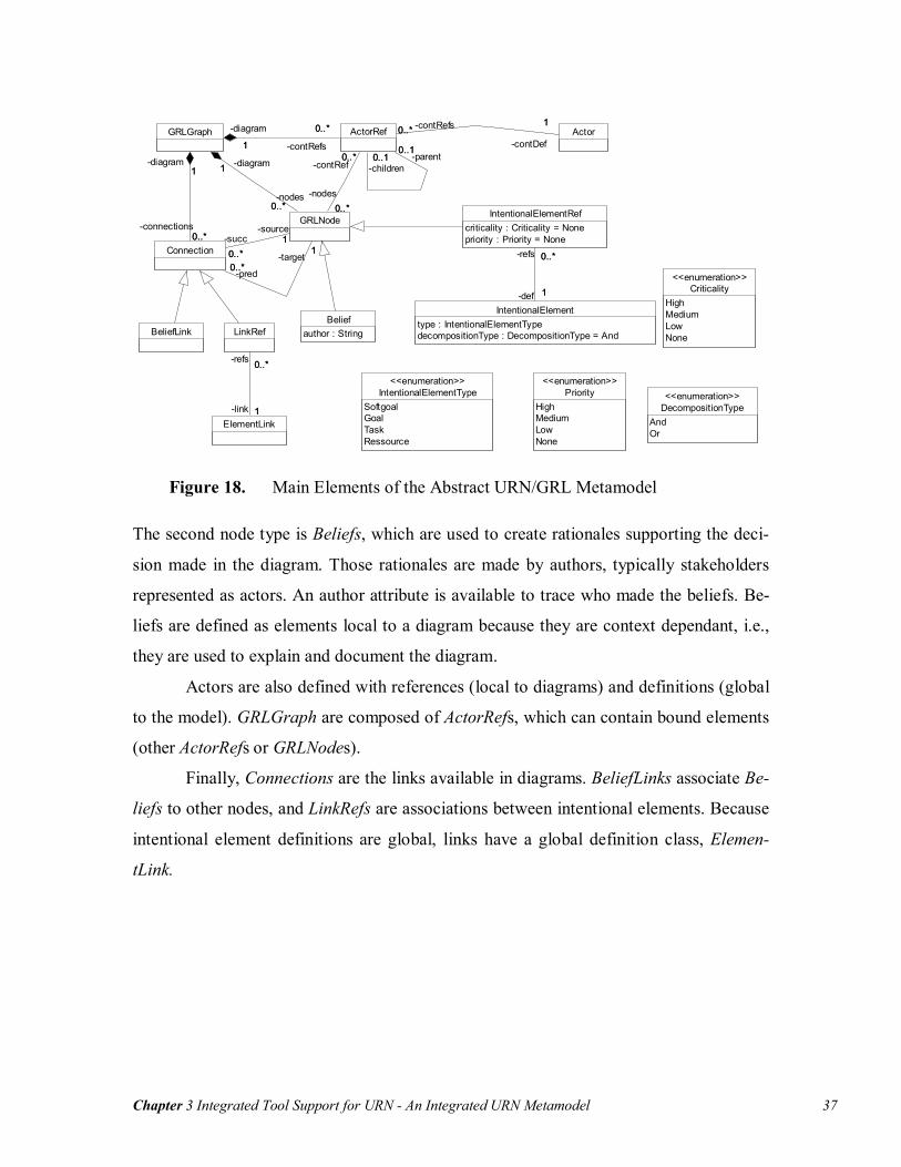
Chapter 3 Integrated Tool Support for URN - An Integrated URN Metamodel 37
Beliefauthor : String
IntentionalElementRefcriticality : Criticality = Nonepriority : Priority = None
IntentionalElementtype : IntentionalElementTypedecompositionType : DecompositionType = And
0..*
1
-refs 0..*
-def 1
ElementLink
LinkRef
1
0..*
-link 1
-refs 0..*
BeliefLink
ActorGRLGraph ActorRef
0..10..* -parent
0..1
-children0..*
10..*
-contDef
1-contRefs0..*0..*
1
-contRefs
0..*-diagram
1
Connection0..*
1
-connections0..*
-diagram1
GRLNode0..*
1
-nodes0..*
-diagram
10..1
0..*
-contRef0..1
-nodes0..*
10..*
-source1-succ
0..*0..*
1
-pred0..*
-target1
PriorityHighMediumLowNone
<<enumeration>>IntentionalElementType
SoftgoalGoalTaskRessource
<<enumeration>>
DecompositionTypeAndOr
<<enumeration>>
CriticalityHighMediumLowNone
<<enumeration>>
Figure 18. Main Elements of the Abstract URN/GRL Metamodel
The second node type is Beliefs, which are used to create rationales supporting the deci-
sion made in the diagram. Those rationales are made by authors, typically stakeholders
represented as actors. An author attribute is available to trace who made the beliefs. Be-
liefs are defined as elements local to a diagram because they are context dependant, i.e.,
they are used to explain and document the diagram.
Actors are also defined with references (local to diagrams) and definitions (global
to the model). GRLGraph are composed of ActorRefs, which can contain bound elements
(other ActorRefs or GRLNodes).
Finally, Connections are the links available in diagrams. BeliefLinks associate Be-
liefs to other nodes, and LinkRefs are associations between intentional elements. Because
intentional element definitions are global, links have a global definition class, Elemen-
tLink.

Chapter 3 Integrated Tool Support for URN - An Integrated URN Metamodel 38
Decomposition
Contributioncontribution : ContributionType = Unknowncorrelation : boolean = false
Dependency
ElementLink
IntentionalElementtype : IntentionalElementTypedecompositionType : DecompositionType = And
0..* 1
-linksSrc0..*
-src
1
1
0..* -dest
1
-linksDest0..*
ContributionTypeMakeHelpSomePositiveUnknownSomeNegativeHurtBreak
<<enumeration>>
Figure 19. GRL Links Metamodel
Figure 19 shows the ElementLinks supported by the metamodel, whose instances of De-
composition, Contribution or Dependency. Each link has a source and a destination inten-
tional element. The destination element is the intentional element that has its evaluation
level affected by the link. A Correlation is modeled as an attribute of Contribution (false
by default). Contribution/correlation types (Make, Help, Some Positive, Unknown, Some
Negative, Hurt or Break) are defined in an enumeration (ContributionType).
Dependencies are also links between pairs of intentional elements. To create a
typical three-element GRL dependency relationship, two links have to be instantiated: a
dependency from the dependee (source) to the dependum (destination) and a second de-
pendency from the dependum (source) to the (depender).
The implementation focuses on integrating the Strategic Rationales and Strategic
Dependencies models. However, the metamodel does not support directly dependencies
between actors. Instead, such dependencies are supported by binding intentional elements
to actor references, and by using these two elements in the dependencies.

Chapter 3 Integrated Tool Support for URN - An Integrated URN Metamodel 39
RespRef
repetitionCount : intResponsibi lity
1..*1
-respRefs
1..*
-respDef
1
StartPoint
EndPoint
Stub
dynamic : boolean = falseshared : boolean = false
TimerInBinding1
0..*
-startPoint
1 -inBindings
0..*
OutBinding
1
0..*
-endPoint 1
-outBindings 0..*
PluginBinding
repetitionCount : intprobabil ity : double = 1.0
0..*
0..1
-bindings0..*
-stub0..1
1..*1
-in
1..*
-binding
1
1..*
1 -out
1..*
-binding
1
NodeConnection
probability : double = 1.0
0..1
0..1
-timer0..1
-timeoutPath0..11
0..*
-stubEntry1
-inBindings0..*
1
0..*
-stubExi t1
-outBindings0..*
ComponentElement
PathNode
0..*
1
-succ 0..*
-source1
1
0..*
-target
1
-pred0..*
UCMmap1
0..*
-plugin
1
-parentStub 0..*
1
0..*
-diagram
1
-nodes
0..*
1
0..*
-diagram 1
-connections0..*
ComponentRef
role : Stringrepl icationFactor : int = 1
0..*
1
-contRefs0..*
-contDef1
0..*
0..*
-nodes0..*
-contRefs
0..*
1 0..*
-diagram
1
-contRefs
0..* 0..*
0..1
-chi ldren0..*
-parent0..1
URNmodelElement(from URNcore)
Figure 20. Main Elements of the Abstract URN/UCM Metamodel
The abstract UCM metamodel (Figure 20) defines abstract concepts available in UCM-
maps. These maps contain component references, path nodes, and node connections. The
UCM syntax supports sub-maps via the stub/plug-in binding mechanism. Others typical
nodes in maps (subclasses of PathNode, not shown here) are start/end points, responsibil-
ity references, AND/OR forks/joins, and timers. The complete metamodel also includes
classes and associations describing component and responsibility definitions, perform-
ance annotations, and scenario definitions.
3.2.2 Implementation Metamodel
From the abstract metamodel, an implementation metamodel was developed, which is
used in jUCMNav. The transformation of an abstract syntax metamodel to an implemen-
tation metamodel is accomplished in two steps: refactoring the metamodel with common
concepts for both sub-notation and adding visual elements to the syntax.
First, packages for both URN sub-notations (UCM and GRL) are created
(Figure 21). In addition, the URNcore package is added to define common classes for the
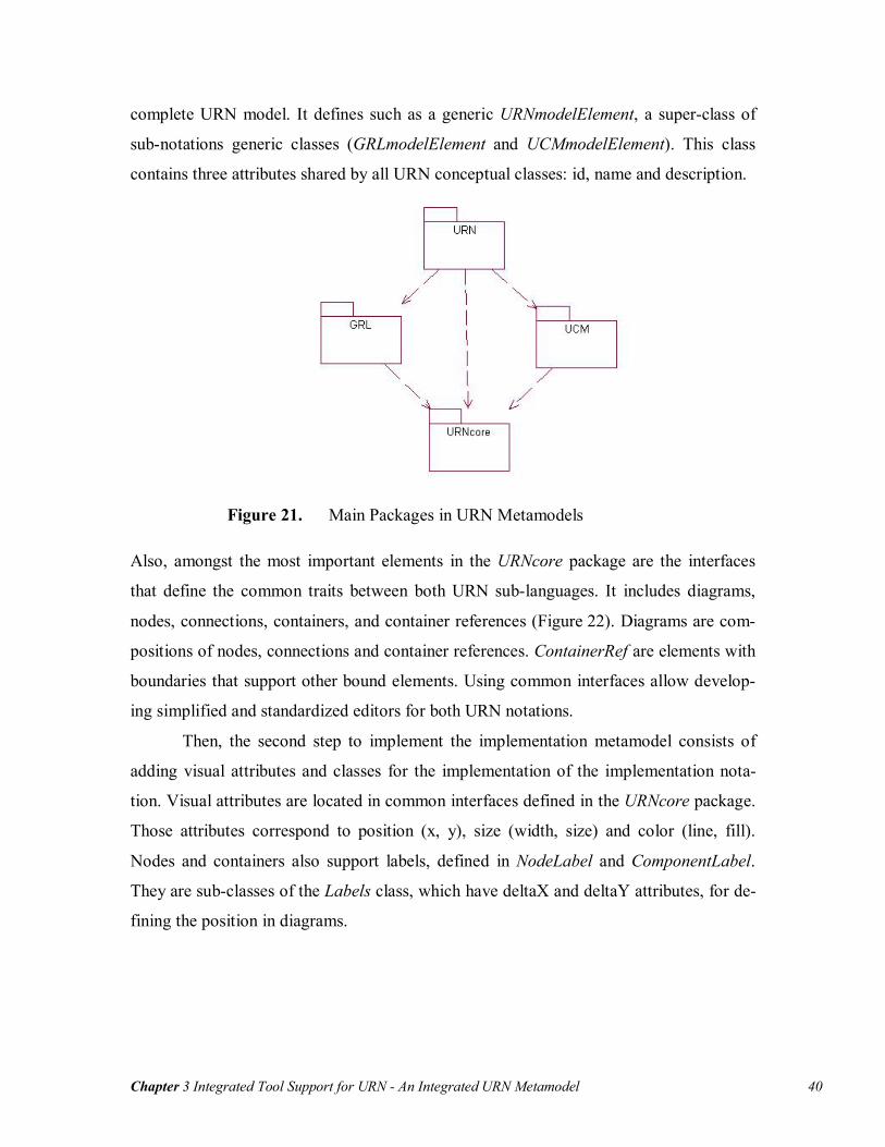
Chapter 3 Integrated Tool Support for URN - An Integrated URN Metamodel 40
complete URN model. It defines such as a generic URNmodelElement, a super-class of
sub-notations generic classes (GRLmodelElement and UCMmodelElement). This class
contains three attributes shared by all URN conceptual classes: id, name and description.
Figure 21. Main Packages in URN Metamodels
Also, amongst the most important elements in the URNcore package are the interfaces
that define the common traits between both URN sub-languages. It includes diagrams,
nodes, connections, containers, and container references (Figure 22). Diagrams are com-
positions of nodes, connections and container references. ContainerRef are elements with
boundaries that support other bound elements. Using common interfaces allow develop-
ing simplified and standardized editors for both URN notations.
Then, the second step to implement the implementation metamodel consists of
adding visual attributes and classes for the implementation of the implementation nota-
tion. Visual attributes are located in common interfaces defined in the URNcore package.
Those attributes correspond to position (x, y), size (width, size) and color (line, fill).
Nodes and containers also support labels, defined in NodeLabel and ComponentLabel.
They are sub-classes of the Labels class, which have deltaX and deltaY attributes, for de-
fining the position in diagrams.
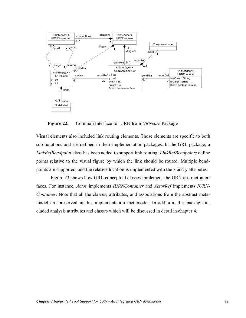
Chapter 3 Integrated Tool Support for URN - An Integrated URN Metamodel 41
IURNContainerlineColor : StringfillColor : Stringfilled : boolean = false
<<Interface>>
ComponentLabel
NodeLabel
IURNContainerRefx : inty : intwidth : intheight : intfixed : boolean = false
<<Interface>>
0..*1
-contRefs0..*
-contDef
1
0..1
1
-contRef
0..1
-label 1
IURNNodex : inty : int
<<Interface>>
1
0..1
-node1
-label0..1
0..* 0..1
-nodes
0..*
-contRef
0..1
IURNDiagram<<Interface>>
1
0..*
-diagram1
-nodes0..*
1
0..*
-diagram1
-contRefs 0..*
IURNConnection<<Interface>>
1
0..*
-source1
-succ0..*
0..*
1
-pred0..*
-target1
10..*
-diagram
1
-connections
0..*
Figure 22. Common Interface for URN from URNcore Package
Visual elements also included link routing elements. Those elements are specific to both
sub-notations and are defined in their implementation packages. In the GRL package, a
LinkRefBendpoint class has been added to support link routing. LinkRefBendpoints define
points relative to the visual figure by which the link should be routed. Multiple bend-
points are supported, and the relative location is implemented with the x and y attributes.
Figure 23 shows how GRL conceptual classes implement the URN abstract inter-
faces. For instance, Actor implements IURNContainer and ActorRef implements IURN-
Container. Note that all the classes, attributes, and associations from the abstract meta-
model are preserved in this implementation metamodel. In addition, this package in-
cluded analysis attributes and classes which will be discussed in detail in chapter 4.
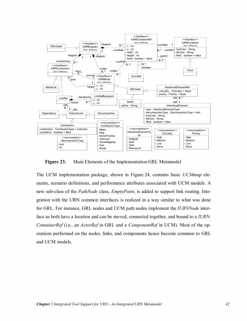
Chapter 3 Integrated Tool Support for URN - An Integrated URN Metamodel 42
Contribution- contribution : ContributionType = Unknown- correlation : boolean = false
Actor
ActorRef
IURNContainer
- lineColor : String- fillColor : String- filled : boolean = false
(from URNcore)
<<Interface>>
IURNNode
- x : int- y : int
(from URNcore)
<<Interface>>
IURNContainerRef
- x : int- y : int- width : int- height : int- fixed : boolean = false
(from URNcore)
<<Interface>>
1
0..* -contDef
1-contRefs
0..*
0..10..*
-parent
0..1
-children0..*0..1
0..*
-contRef0..1
-nodes0..*
IURNConnection(from URNcore)
<<Interface>>
1
0..*-source
1
-succ0..*
0..*
1-pred
0..*
-target1
IURNDiagram(from URNcore)
<<Interface>>
0..*
1
-nodes0..*
-diagram1
0..*
1 -contRefs
0..*-diagram
1
0..*
1-connections 0..*
-diagram1
GRLNode
Belief- author : String
IntentionalElementRef- criticality : Criticality = None- priority : Priority = None
IntentionalElement- type : IntentionalElementType- decompositionType : DecompositionType = And- lineColor : String- fillColor : String- filled : boolean = false
0..*1
-refs 0..*-def 1
ElementLink
LinkRef
10..*-link1
-refs0..*
LinkRefBendpoint- x : int- y : int
1
0..*-linkref
1 -bendpoints
0..*
GRLGraph
BeliefLink
Dependency Decomposition
Priority- High- Medium- Low- None
<<enumeration>>
DecompositionType- And- Or
<<enumeration>>Criticality
- High- Medium- Low- None
<<enumeration>>
ContributionType- Make- Help- SomePositive- Unknown- SomeNegative- Hurt- Break
<<enumeration>>
IntentionalElementType
- Softgoal- Goal- Task- Ressource
<<enumeration>>
Figure 23. Main Elements of the Implementation GRL Metamodel
The UCM implementation package, shown in Figure 24, contains basic UCMmap ele-
ments, scenario definitions, and performance attributes associated with UCM models. A
new sub-class of the PathNode class, EmptyPoint, is added to support link routing. Inte-
gration with the URN common interfaces is realized in a way similar to what was done
for GRL. For instance, GRL nodes and UCM path nodes implement the IURNNode inter-
face as both have a location and can be moved, connected together, and bound to a IURN-
ContainerRef (i.e., an ActorRef in GRL and a ComponentRef in UCM). Most of the op-
erations performed on the nodes, links, and components hence become common to GRL
and UCM models.

Chapter 3 Integrated Tool Support for URN - An Integrated URN Metamodel 43
Figure 24. Main Elements of the Implementation UCM Metamodel
To complete the integration of the two notations, the top-level package URN (Figure 25)
has been added. It includes classes defining global elements in a URNmodel (URNdefini-
tion), as well as GRL and UCM diagram specifications (GRLspec and UCMspec). In ad-
dition, the URNlink defined in this package allows one to define links between any URN
elements. Those links are discussed in detail in Chapter 4.
Finally, the two metamodels were developed to support extensions to URN and to
jUCMNav. Developing new elements will only require extending the common URN in-
terfaces. Also, adding new views to URN models (e.g., UML class diagrams) will simply
require creating a new package for the view, a specification class (such as GRLspec and
UCMspec) and a sub-class of URNmodelElement. Then, after modelling the new classes
that implement URN interfaces and importing the metamodel in jUCMNav, little pro-
gramming will be needed to have a new editor supporting basic functionalities.
RespRef- repetitionCount : int
Responsibility
# empty : boolean = false(f rom URNcore)
1..*
1
-respRefs1..*
-respDef1
UCMmodelElement(from URNcore)
ComponentElement(from URNcore)
Timer
StartPoint
EndPoint
NodeConnection- probability : double = 1.0
0..1
0..1
-timer0..1
-timeoutPath0..1
Stub- dynamic : boolean = false- shared : boolean = false
InBinding1
0..*
-startPoint
1 -inBindings0..*
1
0..*
-stubEntry 1
-inBindings0..*
OutBinding
1
0..*
-endPoint 1
-outBindings 0..*
10..*
-stubExit1
-outBindings0..*
UCMmap
PluginBinding- id : String- repetitionCount : int- probability : double = 1.0
0..*
0..1
-bindings0..*
-stub0..1
1..*
1
-in
1..*-binding
1
1..*
1 -out
1..*
-binding
1
1
0..*
-plugin1
-parentStub 0..*
PathNode
ComponentRef- role : String- replicationFactor : int = 1- anchored : boolean = false
IURNContainer
- lineColor : String- fillColor : String- filled : boolean = false
(f rom URNcore)
<<Interface>>
IURNNode
- x : int- y : int
(f rom URNcore)
<<Interface>>
IURNContainerRef
- x : int- y : int- width : int- height : int- fixed : boolean = false
(f rom URNcore)
<<Interface>>
0..10..*-parent
0..1 -children0..*
1 0..*
-contDef
1
#contRefs
0..*
0..1
0..*
-contRef0..1
#nodes0..*
IURNConnection(f rom URNcore)
<<Interface>>
1
0..*
-source1
#succ0..*
0..*
1
#pred
0..*
-target1
IURNDiagram(f rom URNcore)
<<Interface>>
0..*
1
-nodes0..*
-diagram1
0..* 1
-contRefs
0..*
-diagram
1
0..*
1
-connections0..*
-diagram1

Chapter 3 Integrated Tool Support for URN - jUCMNav as an Integrated URN Tool 44
UCMspec(from UCM)
GRLspec(from GRL)
URNdefinition(from URNcore)
URNspec- name : String- description : String- author : String- created : String- modified : String- specVersion : String- urnVersion : String- nextGlobalID : String
0..1
1
-ucmspec0..1
-urnspec1
0..1
1
-grlspec0..1
-urnspec1
1
1
-urndef 1
-urnspec1
URNmodelElement
- id : String- name : String- description : String
(from URNcore)
URNlink
0..*1
-urnLinks0..*
-urnspec
10..*
1
-fromLinks0..*
-fromElem 1 1
0..*
-toElem1
-toLinks0..*
Figure 25. Element of the URN Implementation Package
3.3 jUCMNav as an Integrated URN Tool
Adding a GRL editor to jUCMNav required a major refactoring of the original code.
However, maintainability and extensibility were addressed during the first development
phase, which decreased the development effort. This section presents the architecture and
implementation of the tool. Then, an overview of the editing features for GRL is pre-
sented.
3.3.1 Architecture and Implementation
As discussed in chapter 2, jUCMNav is a Java plug-in for Eclipse that takes advantage of
EMF and GEF. It also depends on Eclipse’s Standard Widget Toolkit (SWT), which is a
user interface plug-in supporting multiplatform graphical user interfaces by abstracting
the operating system specific libraries.
Figure 26 gives an overview of jUCMNav’s architecture and dependencies,
through its high-level components. The extension mechanism allows developers to im-
plements add-ons to extend the jUCMNav features. Also, the URN models generated in
the tool can be exported in various formats, such as graphics, DXL scripts or GRL cata-
logues (to be discussed in section 3.4).

Chapter 3 Integrated Tool Support for URN - jUCMNav as an Integrated URN Tool 45
Figure 26. Overview of jUCMNav Architecture and Dependencies
From the UML implementation metamodel, EMF automatically generated nearly 100
classes. Because changes in the URN metamodel are automatically replicated in the Java
implementation, the software evolution and maintenance is greatly simplified. We pro-
duced about a dozen major versions of the URN implementation metamodel, with mini-
mal impact on the code existing at the time. Also, the framework supports model persis-
tence via XMI serialization [43], which automates the saving/loading of models.
The Java classes generated using EMF implement EObject, an interface that is a
sub-class of Notifier. This super-class is used to implement the observer design pat-
tern [16], where external objects can register themselves as observers and receive notifi-
cations when changes occur in the observed objects. Combined with a Model-View-
Controller architecture, this keeps the state of the model views synchronized with the
state of the model. Hence, changes generated in a view are reflected in the other views.
The combined use of EMF with GEF imposed such architecture, which ended up
facilitating the implementation of the editors. In GEF, each editable object must be asso-
ciated to an EMF object. When an object is selected, a new instance of its properties is
returned. These properties, defined in classes that implement the PropertySource inter-

Chapter 3 Integrated Tool Support for URN - jUCMNav as an Integrated URN Tool 46
face, correspond to a hierarchical list of properties associated to the model attributes or
references. They are displayed in the Properties View, in control such as text boxes, se-
lection dialogs, or drop-down boxes.
The EditParts are the controllers between a view and the model (model observ-
ers). They define how model instances are shown in a view. Also, EditPolicies define the
actions that can be executed on their associated objects. Those actions, which are imple-
mented using the Command design pattern [16], are events such as creation/deletion of
objects or modifications of their attributes/references.
3.3.2 Basic Editing Features for GRL
The GRL extension is implemented using a generalization of common parts of the code,
such as abstract URN editor. Because of the complexity of GRL models and their evolu-
tion over time, it is possible to develop a model over multiple diagrams, using multiple
instances of the same elements. This is implemented in jUCMNav using a multi-page edi-
tor for the main view, which supports multiple URN editors (URN diagrams). The GRL
editor is implemented as a sub-class of the abstract URN editor.
As shown in Figure 27, the main editor has a palette (at the right of the figure) to
create the GRL elements and links. The EditPolicies are used to support on-the-fly feed-
back and prevent users from executing invalid actions. For example, a user will not be
able to add links between two elements that have a link already defined. The set of Edit-
Policies is particularly useful to manage definitions and references through all the dia-
grams, preventing the user from creating syntactically invalid URN models. Browsing
multiple diagrams in the model can be done using the tabs at the bottom of the main edi-
tor.
When a new intentional element or actor is dragged and dropped from the palette
to the editor, two elements are created: a reference in the diagram and a definition in the
model. Using the properties view, one can modify the definition of an element in the dia-
gram. The hierarchical outline view contains all the references in diagrams as well as the
definitions in the model. From this view, it is possible to drag and drop a definition in a
diagram, which automatically creates a new reference in the corresponding diagram. To
delete an element using the outline view, all it references must have been deleted first.

Chapter 3 Integrated Tool Support for URN - jUCMNav as an Integrated URN Tool 47
Definitions are not deleted automatically when all their references are deleted because
modellers may want to reference it later in the model. However, this behaviour can lead
to a model with many unreferenced definitions. In the outline, unreferenced definitions
are displayed in gray to identify them easily.
A similar implementation is available for links. Using the palette to build links
creates a reference between the two intentional elements in the editor. In addition, the
link definitions are available under each of the intentional element definition, in the out-
line. For model readability, a new link between 2 elements does not create links between
each of their references. It is the modeller’s responsibility to add these references in the
views. However, dragging and dropping elements from the outline to diagrams adds by
default all the link references (to other elements also available in the diagram). Deleting
the latest reference to a link also delete its definition. This behaviour is implemented be-
cause unreferenced links would have been hard to manage for modellers. Such unrefer-
enced links would also have an impact on model analysis, which could cause misleading
results.
Beliefs are implemented as comments in jUCMNav. They are use to keep ration-
ales provided by the stakeholders or modellers. In the draft standard, the belief links can
modify the evaluation level of an intentional element or an association. This feature can
be confusing since belief evaluations modify the model results.
In our editor, belief links are associated to intentional elements affected by be-
liefs, but they do not affect the evaluation level. We have implemented new analysis
mechanisms to support multiple evaluations (chapter 4), which we consider easier to use
than belief evaluations. In addition, beliefs are local to GRL diagrams. The author attrib-
ute of a belief is set by default to the operating system username, which simplifies the
tracking of comments from multiple modellers.

Chapter 3 Integrated Tool Support for URN - jUCMNav as an Integrated URN Tool 48
Figure 27. GRL Editor in jUCMNav
Intentional elements use an automatic resizing algorithm in order to minimize the image
size based on the name of the elements. When an element is larger than the default size, it
uses multiple lines to display its name if this can reduce the element width. Another
mechanism used to improve the readability of diagrams is the possibility of adding bend-
points to links, to indicate routing. Bendpoints allow modellers to control how links are
displayed.
As for its UCM counterpart, the Element View is available to display the names
and descriptions of the GRL intentional elements referenced in the current diagram. Fi-
nally, contributions are shown using the icon labels and the name. The possibility of hav-
ing the contribution icons and names can facilitate the understanding of the diagrams by
new users of the notation.
Finally, an optional auto-layout mechanism, previously available for UCM, is im-
plemented for GRL. It relies on Graphviz [40] to position diagram elements. This feature
is necessary to support the automatic generation of diagrams, which is required particu-
larly in the context of reverse/round-trip requirements engineering. It is also required to
develop usable GRL catalogues, which are explored in the next section.

Chapter 3 Integrated Tool Support for URN - Goals Catalogues 49
3.4 Goals Catalogues
Supporting reusable models is a requirement for GRL. However, there are no usable
mechanisms in other tools to do so. jUCMNav supports GRL catalogues, which are reus-
able artefacts that can be imported in a URN model. This feature enables the develop-
ment of reusable high-level models for particular non-functional requirements by ab-
stracting the specific usage context.
3.4.1 Catalogue Design and Implementation
GRL catalogues are repositories of reusable GRL models, or patterns, often used to de-
scribe common model elements and relationships related to non-functional aspects. Mod-
ellers can reuse the catalogues to start new models or add concerns to existing ones. A
catalogue has a name, a description, an author, and a list of intentional elements, followed
by a list of their links. Actors are excluded from the catalogues because they are mostly
domain specific.
Catalogues are described as standalone XML files. The main advantage of im-
plementing catalogues in external files is that they not depend on jUCMNav. Other tools
can use them in the future, or they can be produced by other tools as well. Also, in
jUCMNav, they are implemented using the import/export mechanism provided by
Eclipse. Thus, they are created from standard URN models, and do not require the devel-
opment of a new editor. However, modifications to catalogues must be done through im-
porting and exporting them. In addition, once a catalogue is created, the model used to
create the catalogue and the derived catalogues may evolve in parallel.
Eclipse supports importers/exporters using extension points, which are interfaces
to extend plug-in functionalities. Other features that currently use extension points in-
clude the image exporter and the UCEd importer (discussed in chapter 2). In jUCMNav,
import/export extensions are supported using classes that implements the IURNIm-
port/IURNExport interfaces.
To export a URN model, URNspec, a high-level object for URN model, is used by
the exporter. It enables traversing the list of intentional element definitions and inserting
them in the XML file with their exported attributes (id, name, description, element type
and decomposition type). Then, contributions and decomposition are exported, using ref-
Chapter 3 Integrated Tool Support for URN - Goals Catalogues 50
erences to intentional element identifiers for the source and destination elements. In addi-
tion, contributions are exported with the contribution type and correlation attributes. For
further information on the GRL catalogues representation, an XML schema is available
in Appendix A. Note that current exporter uses the complete URN model to export a cata-
logue. However, generating a catalogue for a specific GRL diagram (based on the refer-
ences) could be implemented easily but is left for future work.
Once a catalogue is created, modellers use the jUCMNav importer to import it in
other URN models. By parsing the XML file, intentional elements and link definitions
are created. Using the auto-layout mechanism, a new GRL diagram is generated that in-
cluded all the elements and associations from the GRL catalogues. Then, one can use
these elements and links in their models to add domain-specific actors and dependencies.
3.4.2 Example of a Security Catalogue
Catalogues are useful to represent and reuse high-level models for non-functional re-
quirement models such as security models [13]. In this section, a catalogue that models
security for client-server applications is developed. The GRL model representing the
catalogue is shown in Figure 28.
In the context of client-server applications, security must be available in the ter-
minal and in the host. Those two softgoals help achieving security, but do not guarantee
it, which explains why the links are modeled as contributions. Then, the catalogue in-
cludes two sample concrete solutions for security (tasks): access authorization and en-
cryption. These two tasks help satisfy the security of the terminal and the security of the
host.
Access authorization is composed of two goals, identification and authentication.
They are modeled with an OR decomposition, which indicates that only one element in
this decomposition needs to be satisfied in order to satisfy the destination (access authori-
zation). Three typical alternative solutions are available to support authentication: card-
key, password or biometric.
The XML file generated by the exporter from this URN model is also shown in
Figure 28.
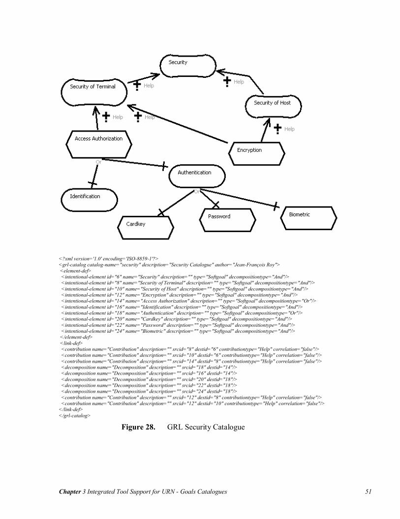
Chapter 3 Integrated Tool Support for URN - Goals Catalogues 51
<?xml version='1.0' encoding='ISO-8859-1'?> <grl-catalog catalog-name="security" description="Security Catalogue" author="Jean-François Roy"> <element-def> <intentional-element id="6" name="Security" description="" type="Softgoal" decompositiontype="And"/> <intentional-element id="8" name="Security of Terminal" description="" type="Softgoal" decompositiontype="And"/> <intentional-element id="10" name="Security of Host" description="" type="Softgoal" decompositiontype="And"/> <intentional-element id="12" name="Encryption" description="" type="Softgoal" decompositiontype="And"/> <intentional-element id="14" name="Access Authorization" description="" type="Softgoal" decompositiontype="Or"/> <intentional-element id="16" name="Identification" description="" type="Softgoal" decompositiontype="And"/> <intentional-element id="18" name="Authentication" description="" type="Softgoal" decompositiontype="Or"/> <intentional-element id="20" name="Cardkey" description="" type="Softgoal" decompositiontype="And"/> <intentional-element id="22" name="Password" description="" type="Softgoal" decompositiontype="And"/> <intentional-element id="24" name="Biometric" description="" type="Softgoal" decompositiontype="And"/> </element-def> <link-def> <contribution name="Contribution" description="" srcid="8" destid="6" contributiontype="Help" correlation="false"/> <contribution name="Contribution" description="" srcid="10" destid="6" contributiontype="Help" correlation="false"/> <contribution name="Contribution" description="" srcid="14" destid="8" contributiontype="Help" correlation="false"/> <decomposition name="Decomposition" description="" srcid="18" destid="14"/> <decomposition name="Decomposition" description="" srcid="16" destid="14"/> <decomposition name="Decomposition" description="" srcid="20" destid="18"/> <decomposition name="Decomposition" description="" srcid="22" destid="18"/> <decomposition name="Decomposition" description="" srcid="24" destid="18"/> <contribution name="Contribution" description="" srcid="12" destid="8" contributiontype="Help" correlation="false"/> <contribution name="Contribution" description="" srcid="12" destid="10" contributiontype="Help" correlation="false"/> </link-def> </grl-catalog>
Figure 28. GRL Security Catalogue

Chapter 3 Integrated Tool Support for URN - Model Creation Example: a Client-Server Application 52
3.5 Model Creation Example: a Client-Server Application
This section presents a simple case study that uses jUCMNav to develop a URN model.
The context is the following. Since security has become important for an organization
that develops Web-based applications, this organization is considering improving how to
access it applications securely. A URN model is used to evaluate the impact of different
solutions on other non-functional requirements. The corresponding high-level architec-
tures are also developed. For this model, the security catalogue from the preceding sec-
tion is reused.
First, a high-level domain-specific model is created. There are three actors for the
Web-based applications, which corresponded to the stakeholders of the systems (Man-
agement, Shareholders, and Users). Those stakeholders have different concerns. The
management of the organization is concerned with the project’s cost, modeled as a goal.
Then, shareholders are concerned with getting the maximum return on their investment.
Finally, the system users want an application that is easy to use. This concern corre-
sponds to a non-functional requirement, or softgoal in GRL. Those intentional elements
are bound to their corresponding actors (as shown in Figure 29).
The next step is the modelling of relationships between intentional elements.
There is a relation between minimum cost and return on investment, where minimizing
the cost helps getting a higher return on investment. This is modeled using a Help contri-
bution. Then, to achieve a higher return on investment, users should use the developed
system. However, having them use systems implies addressing their main concern, which
is system usability in this example. A new softgoal corresponding to system usage is
added to the model and has a Help contribution from the usability softgoal. Furthermore,
a two-element dependency is used to represent that return on investment depends on the
system usage. Finally, it is assumed that users need training, modelled here with a task, in
order to adopt a system. This task improves system usage, but makes a negative contribu-
tion to the cost of the system.

Chapter 3 Integrated Tool Support for URN - Model Creation Example: a Client-Server Application 53
Figure 29. High-level View of Actor Concerns
Once the high-level GRL model is developed, the security catalogue can be imported.
This creates a GRL diagram with the definitions found in the catalogue. The catalogue
model is integrated by linking authentication tasks to the cost. The card key, biometric
and password tasks contribute to the cost (Some Negative, Hurt and Some Positive re-
spectively). Then, encryption has a side effect on the performance of the system. This
side-effect is modelled with a Some Negative correlation. Finally, performance has an
influence on the usability of the tool, represented with a Some Positive contribution. The
integrated GRL diagram is presented in Figure 30.
Next, operational and architectural aspects of the system are modeled with a
UCM. The model has three main components, corresponding to users, servers and clients
(Figure 31). A request to a Web application is represented as a path starting from the us-
ers and going to the client, who verified the request. If it is an invalid request (represented
with an OR fork), an error message is sent back to users. However, if the request is valid,
users provide authentication information, which is sent to the authentication service. A
dynamic stub is used to model different implementations of authentication. If an error

Chapter 3 Integrated Tool Support for URN - Model Creation Example: a Client-Server Application 54
occurs during authentication, the client sends back an error message to the users, and if
not, the request is sent to the encryption module. Then, the server decrypts the request
and processes it. A log is written on the server when, in parallel (modelled with an AND
fork), the result is sent to the users.
Figure 30. Integration of the Security Catalogue
Figure 31. Web Request UCM Model
Chapter 3 Integrated Tool Support for URN - Chapter Summary 55
3.6 Chapter Summary
In this chapter, jUCMNav was enhanced to support GRL. It integrates both sub-notations
of URN using a graphical editor and different Eclipse views. In section 3.1, we presented
the requirements and rationales that drove the development of the tool. Then, the inte-
grated metamodel for URN was described (section 3.2), which includes a metamodel for
the abstract syntax and a metamodel for the tool implementation. Section 3.3 explained in
details the architecture and implementation of jUCMNav, as well as how GRL is sup-
ported. Then, supporting reusable model, through GRL catalogues, was detailed in sec-
tion 3.4. This section also includes the description of a security catalogue, which is re-
used in section 3.5 to develop a simple Web-application case study that uses jUCMNav.
The next chapter will address the new GRL analysis mechanisms developed in
jUCMNav. Also, it will explain and show how to link GRL and UCM elements, and will
describe how to use these links in model analysis.
Chapter 4 Analysis of URN Models - A New Evaluation Algorithm 56
Chapter 4 Analysis of URN Models
By providing access to the complete URN model, jUCMNav can offer novel analysis
mechanisms. In this chapter, the new concept of GRL strategies is presented. It is based
on a new, extensible analysis algorithm that uses numerical evaluations. In addition, a
new metric associated with actors is described. To measure the impact of GRL strategies
on the architectural aspects, traceability links are developed between the two URN sub-
notations.
4.1 A New Evaluation Algorithm
This section presents a new evaluation algorithm used to measure the satisfaction level of
GRL intentional elements. Using a numerical evaluation scale, this evaluation mechanism
tends to be easier to use than the typical qualitative scale. Also, an adaptable algorithm is
used that deals with all intentional links in the model.
4.1.1 From Qualitative to Quantitative Evaluations
In GRL, intentional element satisfaction levels are shown graphically using a qualitative
scale – satisfied, weakly satisfied, undecided, conflict, weakly denied and denied (see
Figure 4 on page 12). During the project’s requirements elicitation phase, we realized that
some users are interested in having a quantitative interpretation of satisfaction levels. The
advantage of such approach is the larger range (granular representation) of evaluations. It
is particularly useful to represent weakly satisfied/denied labels. In addition, numerical
evaluations are easier to understand, particularly for new users of the notation.
The chosen numerical representation of the satisfaction level creates values be-
tween -100 (denied) and +100 (satisfied), which is a simple and yet intuitive range of val-
ues. In the qualitative representation, there are two labels with similar meaning: unknown
and conflict. The difference was that in the first case, the user-defined evaluations do not
allow calculating an evaluation for a particular element whereas, in the second case, the

Chapter 4 Analysis of URN Models - A New Evaluation Algorithm 57
link labels generate conflicting evaluations. Because the proposed evaluation algorithm
(section 4.2) resolves conflicts automatically, there is no numerical representation of the
conflict label used in the quantitative scale.
Name Qualitative Representation Quantitative Representation Satisfied (Satisficed)
100
Weakly Satisfied (Satisficed)
1 to 99
Unknown
0
Weakly Denied
-1 to -99
Denied
-100
Table 5 Default Correspondence between Qualitative and Quantitative Evaluations
In jUCMNav, both qualitative and quantitative representations are used. In addition, in-
tentional elements are optionally color-coded with shades varying from red (-100) to
green (+100). The default value for elements is unknown, or 0 (yellow).
The numerical values represent an approximation of the satisfaction level of in-
tentional elements. Due to the fuzzy nature of non-functional requirements, it is not pos-
sible to measure their satisfaction precisely. For example, usability of a system is a re-
quirement that is relative to the user’s perception. Some users can consider a system us-
able when others are unable to use it. Hence, an element that has an evaluation of 100 (or
-100) is defined as an element that is sufficiently satisfied (or denied).
4.1.2 Algorithm
Using numerical labels for element satisfaction requires the development of a new GRL
analysis algorithm. With the various domains where GRL is used, the evaluation algo-
rithm is required to be flexible and adaptable to different contexts. Furthermore, even if
the GRTool algorithm [18] and the NFR framework algorithm [13] inspired some parts of
the proposed algorithm, these algorithms are semi-automated and need user inputs to re-
solve conflicts generated during evaluations. The new GRL algorithm is a fully-
automated algorithm with an automatic conflict resolution mechanism. In addition, it uses
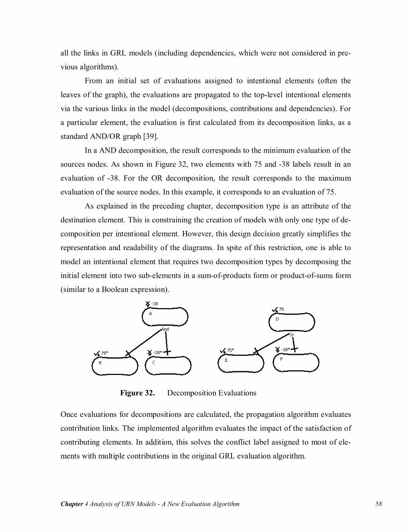
Chapter 4 Analysis of URN Models - A New Evaluation Algorithm 58
all the links in GRL models (including dependencies, which were not considered in pre-
vious algorithms).
From an initial set of evaluations assigned to intentional elements (often the
leaves of the graph), the evaluations are propagated to the top-level intentional elements
via the various links in the model (decompositions, contributions and dependencies). For
a particular element, the evaluation is first calculated from its decomposition links, as a
standard AND/OR graph [39].
In a AND decomposition, the result corresponds to the minimum evaluation of the
sources nodes. As shown in Figure 32, two elements with 75 and -38 labels result in an
evaluation of -38. For the OR decomposition, the result corresponds to the maximum
evaluation of the source nodes. In this example, it corresponds to an evaluation of 75.
As explained in the preceding chapter, decomposition type is an attribute of the
destination element. This is constraining the creation of models with only one type of de-
composition per intentional element. However, this design decision greatly simplifies the
representation and readability of the diagrams. In spite of this restriction, one is able to
model an intentional element that requires two decomposition types by decomposing the
initial element into two sub-elements in a sum-of-products form or product-of-sums form
(similar to a Boolean expression).
Figure 32. Decomposition Evaluations
Once evaluations for decompositions are calculated, the propagation algorithm evaluates
contribution links. The implemented algorithm evaluates the impact of the satisfaction of
contributing elements. In addition, this solves the conflict label assigned to most of ele-
ments with multiple contributions in the original GRL evaluation algorithm.

Chapter 4 Analysis of URN Models - A New Evaluation Algorithm 59
For each contribution x of a destination element with N contributions, the satisfaction
level of the source element and the contribution level are used (described in Algorithm
1). Note that contributions with unknown evaluation as source elements are not consid-
ered in the algorithm. This behaviour allows viewing immediately the impact of contribu-
tions on the higher-level intentional elements, even if other contributions are set to un-
known.
The contribution level, LEVx, is given a numerical value between -1 and 1 accord-
ing to the contribution type on the link (1 for make, 0.5 for help, 0.25 for some positive, 0
for unknown, -0.25 for some negative, 0.5 for hurt, and -1 for break). The satisfaction
level of the source element, NEVALx, is normalized to a value between 0 (denied) and
100 (satisfied). The normalized evaluation is multiplied by the contribution level. The
results of each of the contributions are added and normalized to provide the total contri-
bution, TCON, a value between -100 and 100.
Name: Contribution Evaluation Inputs:
- NEVAL: int[] - LEV: int[] - TOLERANCE: int
Outputs: - TCON: int
if ( TCON >= |100|) then TCON = 100 * (TCON/|TCON|) endif if ( (TCON >= (100 – TOLERANCE)) and (LEVx=1..n ≠ 1) ) then TCON = 100 - (1 + TOLERANCE) else if ( (TCON <= (-100 + TOLERANCE)) and (LEVx=1..n ≠ -1) ) then TCON = -100 + ( 1 + TOLERANCE) endif endif
Algorithm 1 Contribution Evaluation Algorithm
∑=
×=N
xxx LEVNEVALTCON
1

Chapter 4 Analysis of URN Models - A New Evaluation Algorithm 60
The normalized evaluation is calculated using a tolerance attribute, TOLERANCE, which
is set to 0 by default. This parameter is configurable, and in jUCMNav, it can be modi-
fied by the user through the tool’s Preference page. The tolerance defines the range of
values that are considered satisfied or denied. For example, with a tolerance of 10,
evaluations between 90 and 100 are considered fully satisfied while evaluations between
-90 and -100 are considered fully denied. For most cases, the default tolerance is suffi-
cient. However, in some situations, one can modify this value to fit the context of the
model.
The second part of Algorithm 1 normalizes the contribution result to a value be-
tween -100 + (1 + TOLERANCE) and 100 - (1 + TOLERANCE) , corresponding to
weakly denied/satisfied, if none of the contributions are denied/make contributions. This
leads to a behaviour where an infinite number of help contributions (positive but insuffi-
cient) still results in a weakly satisfied evaluation.
Once the contributions for an element are evaluated, the result is added to the re-
sult from the decompositions (0 if no decompositions). The result is again normalized
between -100 and +100 if it is out of bounds. Figure 33 shows typical examples of single
contribution evaluations.
Figure 33. Contribution Evaluations
Finally, the dependencies are evaluated. A dependency is defined as an element that
needs another element to be satisfied. It can never have a higher evaluation than the ele-
ment it depends on. Thus, the algorithm uses the minimal value among the dependees. If
this value is less than the result from the preceding steps, the final result corresponds to
the dependee value.

Chapter 4 Analysis of URN Models - GRL Strategies 61
Figure 34. Dependency Evaluations
Figure 34 shows a case where an element A depends on two other elements, B and D.
Those two elements also depend on elements C and E respectively. By default, evalua-
tions are set to 0. Element C does not influence the evaluation of B because it is greater
than the default evaluation. However, element E is less than the default evaluation of
element D, which causes D’s evaluation to become -30. This value is in turn propagated
to element A.
4.2 GRL Strategies
The evaluations assigned to intentional elements are based on many aspects, such as de-
sign decisions, stakeholders, organizational priorities, user beliefs and many other vari-
ables. The concept of GRL strategies is developed to compare the overall results of those
variables on the models. It provides two different analysis labels on the model: one for
intentional elements and one for actors.
4.2.1 Intentional Element Labels
GRL strategies are defined as user-defined sets of initial evaluations. This approach is a
flexible replacement to belief evaluations, which was hard to use in tools like OME.
As shown in the strategies metamodel (Figure 35), the strategies (Evaluation-
Strategy) can be grouped using StrategiesGroup. Groups and strategies are also sub-
classes of URNmodelElement, and inherit its attributes (id, name and description) in the
implementation metamodel. Each strategy also has an author attribute, which is used for
traceability to the originating stakeholder. Like beliefs, strategies are hypotheses and de-
cisions based on a given context.
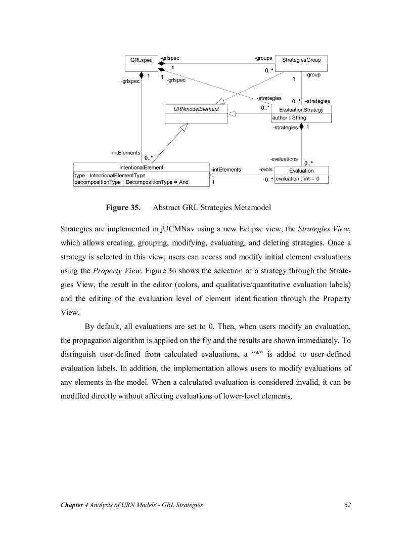
Chapter 4 Analysis of URN Models - GRL Strategies 62
URNmodelElement
IntentionalElementtype : IntentionalElementTypedecompositionType : DecompositionType = And
Evaluationevaluation : int = 01 0..*
-intElements
1
-evals
0..*
StrategiesGroupGRLspec
0..*
1
-intElements0..*
-grlspec1
1 0..*
-grlspec
1
-groups
0..*
EvaluationStrategyauthor : String
0..*
1
-evaluations0..*
-strategies 1
0..*
1
-strategies0..*
-group11
0..*
-grlspec1
-strategies
0..*
Figure 35. Abstract GRL Strategies Metamodel
Strategies are implemented in jUCMNav using a new Eclipse view, the Strategies View,
which allows creating, grouping, modifying, evaluating, and deleting strategies. Once a
strategy is selected in this view, users can access and modify initial element evaluations
using the Property View. Figure 36 shows the selection of a strategy through the Strate-
gies View, the result in the editor (colors, and qualitative/quantitative evaluation labels)
and the editing of the evaluation level of element identification through the Property
View.
By default, all evaluations are set to 0. Then, when users modify an evaluation,
the propagation algorithm is applied on the fly and the results are shown immediately. To
distinguish user-defined from calculated evaluations, a “*” is added to user-defined
evaluation labels. In addition, the implementation allows users to modify evaluations of
any elements in the model. When a calculated evaluation is considered invalid, it can be
modified directly without affecting evaluations of lower-level elements.

Chapter 4 Analysis of URN Models - GRL Strategies 63
Figure 36. Modification of Evaluation for a GRL Strategy
The evaluations that are persistent (inserted in the model) are the user-defined evalua-
tions. In the current implementation, only one propagation algorithm is available. How-
ever, in the future, if new algorithms are implemented, this behaviour will allow users to
change the propagation algorithm at run-time.
The implementation of the algorithm is generic and open as it is based on the
strategy design pattern [16]. This pattern offers the possibility to easily implement other
propagation and evaluation algorithms. To implement such extensions, the developer uses
Eclipse extension points. Then, in jUCMNav, users will be able to choose which algo-
rithm to apply to their strategies, through the Preference Page. In addition, the implemen-
tation of GRL strategies will allow one to apply a strategy locally, to fit in its context.
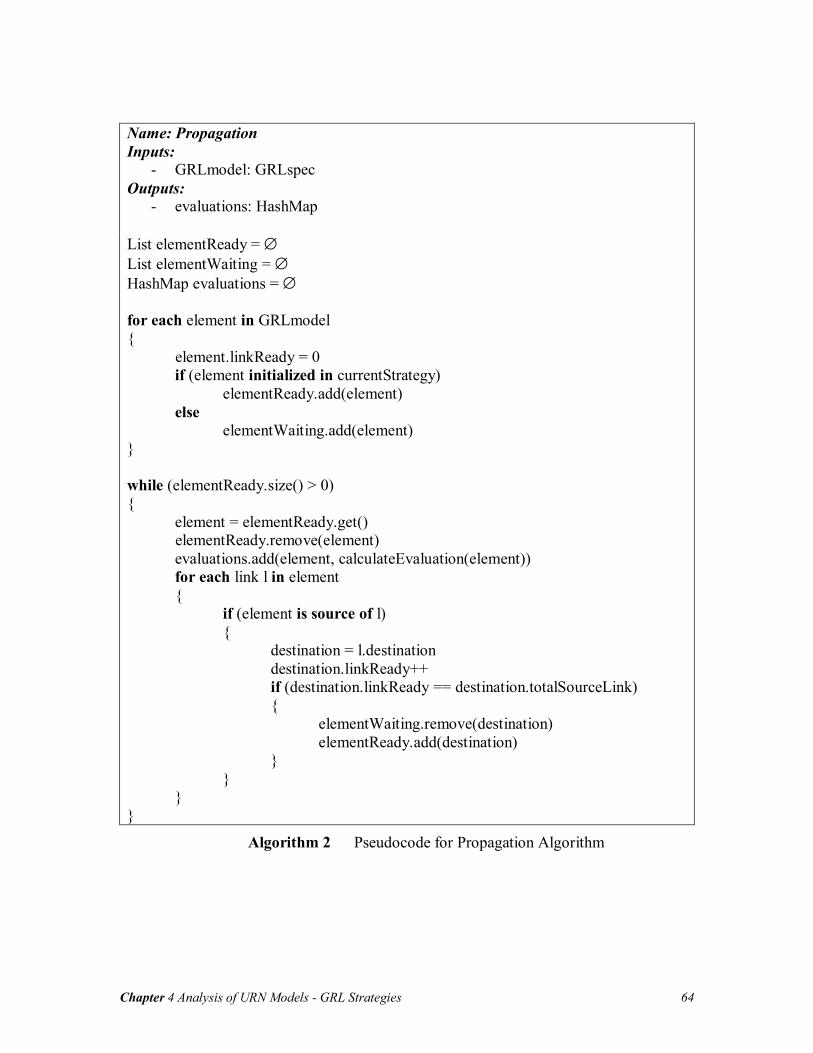
Chapter 4 Analysis of URN Models - GRL Strategies 64
Name: Propagation Inputs:
- GRLmodel: GRLspec Outputs:
- evaluations: HashMap List elementReady = ∅ List elementWaiting = ∅ HashMap evaluations = ∅ for each element in GRLmodel { element.linkReady = 0 if (element initialized in currentStrategy) elementReady.add(element) else elementWaiting.add(element) } while (elementReady.size() > 0) { element = elementReady.get() elementReady.remove(element) evaluations.add(element, calculateEvaluation(element)) for each link l in element { if (element is source of l) { destination = l.destination destination.linkReady++ if (destination.linkReady == destination.totalSourceLink) { elementWaiting.remove(destination) elementReady.add(destination) } } } }
Algorithm 2 Pseudocode for Propagation Algorithm
Chapter 4 Analysis of URN Models - GRL Strategies 65
Extension points are interfaces which must be implemented. The propagation/evaluation
extension point has four functions that must be implemented:
- public void init(EvaluationStrategy strategy, HashMap evaluations); - public boolean hasNextNode(); - public IntentionalElement nextNode(); - public int getEvaluation(IntentionalElement element);
The classes that implement this interface are called by the EvaluationStrategy-
Manager, a singleton object responsible of controlling the access to the strategies. It calls
init with a new strategy to apply. The arguments for this function are the selected strategy
and a hash map of the user-defined evaluations. Then, the propagation algorithm is de-
fined through nextNode function, responsible to return elements ready for their evaluation
(all their lower-level elements were evaluated). Finally, getEvaluation is the function
which implements the evaluation algorithm.
The default propagation algorithm is shown in Algorithm 2. It is implemented in
jUCMNav using the four functions from the extension point interface. It is using two
lists, one for elements that are ready to be evaluated (elementReady), which correspond to
elements with user-defined evaluations for the strategy, and the second list for the other
elements (elementWaiting). First, elements in the ready list are processed. Once the cal-
culated evaluations are available, it increments a counter for each outgoing links (associ-
ate to the destination elements). Once this counter is equal to the total number of incom-
ing links on an element, it is switch from elementWaiting to elementReady list. This is
executed until the elementReady list is empty. If not all the elements are processed, the
default evaluation is used for them (0).
4.2.2 Actor Labels
Combining agent and goal modelling offers the possibility to use both constructs in the
analysis. However, the actors in GRL were not used in previous analysis mechanisms. In
our tool, for a given strategy, a global satisfaction label is associated to actors, which
helps visualize negotiations between stakeholders.
This proposed label is calculated based on the intentional element references
bound to actor references. The label corresponds to a value between -100 and 100, com-

Chapter 4 Analysis of URN Models - GRL Strategies 66
puted from the priority and the criticality of contained intentional element references.
These two attributes can take the values high, medium, low, or none.
In order to model actor concerns on particular goals/requirements, priority and
criticality are associated to references. Different actors can consider concerns differently.
Priority and criticality give the flexibility to deal with this situation. In addition, inten-
tional element references can be used for actor’s requirements negotiation. For example,
in a situation where two actors have conflicting goals, with different visions of the goals,
the labels allow modellers to evaluate the impact of strategies on the actor’s satisfaction.
Through the comparison of strategies, one will be able to choose the strategy that maxi-
mizes the satisfaction of the actors, or that satisfies a particular actor for a particular con-
text.
First, for a specific actor, the algorithm iterates through the actor list of bound in-
tentional element references. Note that multiple element references associated with the
same definition can be bound to the same actor. They are considered as different inten-
tional elements (to allow usage of intentional element in different contexts). Using both
priority and criticality, the evaluation of each element is multiplied by the corresponding
factor (1.5 for high, 1.0 for medium, 0.5 for low and 0 for none), and computes the aver-
age per bound intentional element. Then, it sums both evaluations and normalizes the re-
sult between -100 and 100.
An example of actor evaluation with multiple intentional elements is shown in
Figure 37. In this example, Actor1 and Actor2 have both the same intentional element.
Element A has a low priority and no criticality for Actor1 and it has no priority and a
high criticality for Actor2. In this case, the satisfaction of Actor2 is higher than Actor1.

Chapter 4 Analysis of URN Models - Using GRL Analysis 67
Figure 37. Actor Evaluation Labels
4.3 Using GRL Analysis
To demonstrate how to use the analysis mechanism presents in the preceding section, the
Web application case study presented in 3.5 is revisited. GRL analysis is used to deter-
mine how well security is satisfied based on various options, as well as to what extent the
stakeholders are satisfied.
Usually, user-defined evaluations are set to lower-level elements. In the Web-
application GRL model, those elements correspond to operational tasks. Because of the
operational, concrete properties of tasks, their satisfaction values are Boolean (-100 or
100).
The first step in the analysis consists of creating the strategy groups. In this ex-
ample, groups are created based on the authentication methods evaluated (cardkey, bio-
metric or password). Those authentication methods are never combined in the model be-
cause only one of those is necessary (OR decomposition). For each of the authentication
methods, there are strategies that evaluate the impact of enabling/disabling encryption
and offering, or not, training to users. There are four strategies for each of the three au-
thentication methods: encryption with training, encryption without training, no encryp-
tion with training and no encryption without training.
The next step consists of assigning criticality and priority to intentional element
references. In the Web application model, users are concerned by the usability of the tool.
However, it is not a priority, which is captured by no priority and a low criticality for this
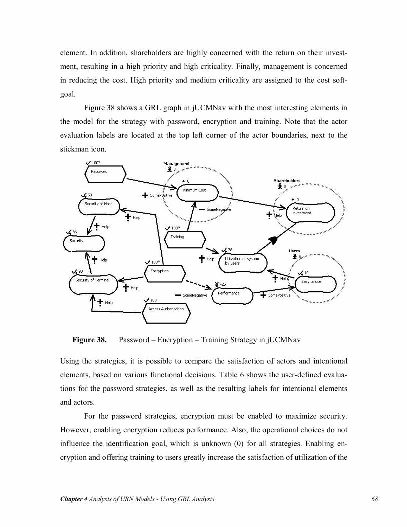
Chapter 4 Analysis of URN Models - Using GRL Analysis 68
element. In addition, shareholders are highly concerned with the return on their invest-
ment, resulting in a high priority and high criticality. Finally, management is concerned
in reducing the cost. High priority and medium criticality are assigned to the cost soft-
goal.
Figure 38 shows a GRL graph in jUCMNav with the most interesting elements in
the model for the strategy with password, encryption and training. Note that the actor
evaluation labels are located at the top left corner of the actor boundaries, next to the
stickman icon.
Figure 38. Password – Encryption – Training Strategy in jUCMNav
Using the strategies, it is possible to compare the satisfaction of actors and intentional
elements, based on various functional decisions. Table 6 shows the user-defined evalua-
tions for the password strategies, as well as the resulting labels for intentional elements
and actors.
For the password strategies, encryption must be enabled to maximize security.
However, enabling encryption reduces performance. Also, the operational choices do not
influence the identification goal, which is unknown (0) for all strategies. Enabling en-
cryption and offering training to users greatly increase the satisfaction of utilization of the

Chapter 4 Analysis of URN Models - Using GRL Analysis 69
system softgoal. Finally, to maximize the actor satisfaction, the strategy with encryption
and without training should be used.
Using the export extension points, jUCMNav supports exporting GRL strategies
with results to comma-separated value files (CSV). These files can be imported by
spreadsheet applications to generate tabular representations of the strategies. The files are
created with the scenario names as row headers, and the actors/intentional elements as
column headers. Then, each cell corresponds to an element evaluation for the correspond-
ing strategy. In addition, user-defined evaluations are distinguished from calculated
evaluation by adding an “*” at the end of the value. The table generated from the CSV
file that contains the 12 strategies of our example is available in Appendix B.
Password Strategies
Encryption –
Training Encryption - No Training
No Encryp-tion –
Training
No Encryp-tion -
No Training Encryption 100 100 -100 -100Training 100 -100 100 -100Cardkey -100 -100 -100 -100Password 100 100 100 100
User-Defined Evaluations
Biometric -100 -100 -100 -100Security 86 86 38 38Security of Terminal 90 90 50 50Security of Host 50 50 0 0Access Au-thorization 100 100 100 100Identification 0 0 0 0Authentication 100 100 100 100Minimum Cost 0 25 0 25Performance -25 -25 0 0Return on Investment 0 28 0 31Easy to use 10 10 0 0
Calculated Evaluations
Utilization of the system by the users 78 28 50 0Shareholders 0 42 0 46Users 5 5 0 0Actors Management 0 31 0 31
Table 6 Password Strategies for Web Application Case Study

Chapter 4 Analysis of URN Models - Linking Goals and Scenarios: URN Internal Links 70
4.4 Linking Goals and Scenarios: URN Internal Links
The GRL strategies we introduced allow studying the impact of intentional elements on
goal and agent models. However, these intentional elements may also have an influence
on the architectural and scenario models. To deal with such analysis, this section presents
a new construct in URN to support internal links between UCM and GRL elements.
4.4.1 Link Definition and Implementation
Integrating UCM and GRL views in the same tool allows for the creation of various
traceability links between elements from both notations. Those links can help improving
the consistency between the URN views during model evolution.
The GRL syntax [25] has a simple construct, non-intentional element, which de-
fines references to external models. However, it does not have any impact on the GRL
model analysis or on the external model. The concept of URNlinks is introduced to meas-
ure the impact of a modification to any evolving GRL/UCM diagram on the other aspects
of the model. As shown in Figure 25 on page 44, URNlinks have from and to elements,
which are of type URNmodelElement. In the metamodel, most of the URN constructs in-
herit from this superclass.
Even if the metamodel defines links between any element types, the current im-
plementation supports only links from GRL to UCM elements. In addition, we currently
limit the number of links to one for UCM elements. This limitation is to simplify the
UCM analysis based on the strategies. The current constructs supporting links in jUCM-
Nav are intentional elements and actors for GRL and responsibilities, components, and
maps for UCM.
Typically in URN, tasks and resources are the intentional elements that have the
most chances of being used in links. They represent concrete aspects of the solution.
However, in early requirements stage, one can use links at a higher level, with abstract
goals. In addition, links are habitually created between actors and components.
Links are created through a new dialog (see Figure 39), which also allows view-
ing and deleting links in the model. This dialog includes attributes such as the selected
GRL element name, type and description at the top of the dialog. Then, on the left, the
list of current links for an element is available. Finally, new links can be created using the

Chapter 4 Analysis of URN Models - Linking Goals and Scenarios: URN Internal Links 71
two drop-downs. Once the links are created, a symbol (yellow triangle) is displayed at the
top-left corner of the element label (see Figure 41).
Figure 39. URN Links Definition in jUCMNav
Using the links and GRL strategies, it is now possible to evaluate the impact of a strategy
on the UCM model. This is achieved by associating evaluations from GRL elements to
the link destination elements (UCM components, responsibilities or maps). Even if actors
have evaluation labels, their evaluations are not associated with UCM models. Those la-
bels are global satisfaction levels, and they do not have any impact on the operational as-
pects.
Based on the element type, the evaluation in UCM can be interpreted differently.
In the typical situation, UCM elements have associated evaluations of 100, 0, or -100
(satisfied, unknown or denied). These values mean that an element is available or not in
the current architecture. However, in some cases, weakly satisfied (or denied) evaluations
can be displayed in the UCM model. This usually indicates that the GRL model needs
further refinement.
Even if the current URNlinks already have an impact on UCMs, the upcoming
support for UCM scenario in jUCMNav will improve greatly the analysis possibilities
based on the links. This will allow one to evaluate the impact of a strategy on a scenario.

Chapter 4 Analysis of URN Models - Linking Goals and Scenarios: URN Internal Links 72
For example, for links between maps in a dynamic stub and GRL, it would be possible to
use the evaluations from the strategies in the selection conditions for the stub.
4.4.2 Using URN Links
In this section, URN links are added to the Web application case study. Then, the analysis
of the UCM through those links is presented.
a) Password Map
b) Cardkey Map c) Biometric Map
Figure 40. UCM for Authentication Mechanisms
Maps for the Authenticate dynamic stub in Figure 31 on page 54 are first created. These
plug-in maps are shown in Figure 40. For Cardkey and Biometric, there is a branch that
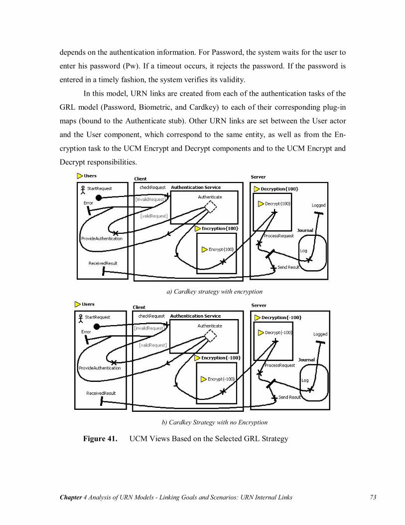
Chapter 4 Analysis of URN Models - Linking Goals and Scenarios: URN Internal Links 73
depends on the authentication information. For Password, the system waits for the user to
enter his password (Pw). If a timeout occurs, it rejects the password. If the password is
entered in a timely fashion, the system verifies its validity.
In this model, URN links are created from each of the authentication tasks of the
GRL model (Password, Biometric, and Cardkey) to each of their corresponding plug-in
maps (bound to the Authenticate stub). Other URN links are set between the User actor
and the User component, which correspond to the same entity, as well as from the En-
cryption task to the UCM Encrypt and Decrypt components and to the UCM Encrypt and
Decrypt responsibilities.
a) Cardkey strategy with encryption
b) Cardkey Strategy with no Encryption
Figure 41. UCM Views Based on the Selected GRL Strategy

Chapter 4 Analysis of URN Models - Chapter Summary 74
Figure 41 shows the result of two GRL strategies on the UCM view. UCM constructs that
have a defined URN link are identified with a yellow triangle at the left of their label. In
this model, if the Encryption task is satisfied (100), then, corresponding components and
responsibilities are available. However, if the task is denied (-100), the corresponding
components and responsibilities are no longer part of the scenario model.
4.5 Chapter Summary
In this chapter, we presented novel analysis mechanisms for URN models. These mecha-
nisms are focused on GRL models. First, we have described a new evaluation algorithm
that uses numerical evaluations. This feature is easier to use and gives more flexibility to
the user than preceding qualitative evaluations. However, the qualitative labels are kept in
the implementation as graphical indicators. Then, the GRL strategies presented in section
3.2 enables the definition and comparison of different sets of initial evaluations. This new
concept will be proposed for standardization in GRL [25] [47]. Strategies have attributes
for traceability, which allow multiple users to define their own sets. In addition, a new
metric for actor evaluation improves coarse-grained model analysis.
Section 4.3 presented an example of the analysis mechanism in GRL using the
Web application case study. Then, in section 4.4, we presented the concept of URN links,
which enables a tighter integration of UCM and GRL. Traceability links are used to pro-
vide feedback on the UCM view based on selected GRL strategies.
In the next chapter, we present how to link GRL elements from/to external re-
quirements. The analysis concepts to be presented in this chapter are used to provide fur-
ther traceability capabilities between general requirements and URN models.

Chapter 5 Linking and Evolving Requirements - Exporting URN Models to DOORS 75
Chapter 5 Linking and Evolving Requirements
Using URN models developed with jUCMNav, it is possible to create links with external
requirements. This chapter describes this approach based on a Requirements Manage-
ment System (RMS), namely Telelogic DOORS, to manage external requirements.
Section 5.1 explains how URN models are exported in a DOORS-compatible
format by jUCMNav. Then, section 5.2 describes the DXL library that supports import-
ing URN and how the internal traceability is managed. Finally, the mechanisms for re-
quirements and model synchronizations are illustrated in section 5.3.
5.1 Exporting URN Models to DOORS
Using URN models in DOORS can be done by developing extensions using DOORS eX-
tension Language (DXL) scripts [27]. The decisions about which elements to export in
the scripts are driven by a few principles and requirements described in the first sub-
section. The support for exporting URN models is implemented directly in jUCMNav, as
an extension point. The implementation is discussed in the second sub-section.
5.1.1 Principles and Requirements for Exporting URN
Requirements Management Systems were developed to manage structured elements,
mainly textual requirements. However, using these systems to manage graphical models
such as URN required adapting the metamodel to the tools structure. As discussed previ-
ously, elements in DOORS are stored in formal modules and are associated together with
links stored in link modules. Using this structure, exported URN models require keeping
a global view of the main elements in the models and linking the main elements to exter-
nal requirements. The export mechanism developed is based on previous works by Jiang
et al. where they exported UCM models to DOORS [27] (presented in Chapter 2).
Having URN models in DOORS ideally requires supporting all the basic con-
structs of the notation. These constructs are definitions, references, containers, contain-

Chapter 5 Linking and Evolving Requirements - Exporting URN Models to DOORS 76
ment relationships, and associations. On the other hand, a minimal number of URN ele-
ments should be exported, to prevent database and export performance degradation. Thus,
the export mechanism should focus on the main semantic elements of the notation that
can conceptually be linked from/to external requirements.
Even if DOORS requires dividing URN constructs into modules, the URN dia-
grams’ integrity should be keep. Traceability between diagrams and their elements should
be preserved, as well as traceability between references and definitions. URN links,
which are useful for traceability analysis, should also be exported. Finally, the dynamic
behaviour of GRL, i.e. strategies and their results, should also be available in DOORS.
The export process consists of importing a DXL file, representing the URN
model, in DOORS. If the model is imported for the first time, the corresponding URN
modules should be created. Those modules correspond to formal modules to store URN
elements, and link modules to capture relations between elements. Once the model is cre-
ated, updating the model should be a matter of reimporting a new DXL file.
To support the URN model in DOORS, a DXL library is installed to provide an
application programming interface (API) for URN elements in the export scripts. This
API creates and updates the elements in DOORS, and manages the internal links between
the elements. It is based on the previously developed library for UCM.
5.1.2 Implementation in jUCMNav
The DXL scripts creation in jUCMNav is implemented as an extension point. As dis-
cussed in chapter 3, extension points were developed to export URN models in various
formats. Developing a new extension point requires one to develop a new class which
implements an export interface. It is hooked to the plug-in in Eclipse using an XML file
that defines the configuration of the extension points.
The DXL export mechanism requires two types of files: a DXL script generated
by traversing the model instances, and images of the URN diagrams. Diagram images are
exported using the image exporter previously developed. DXL scripts and images are
saved in the same location, specified by the user.
The jUCMNav algorithm that creates the DXL scripts starts by writing the header
of the script which is an include statement of the main DXL script file. Then, an initiali-

Chapter 5 Linking and Evolving Requirements - Exporting URN Models to DOORS 77
zation function is called with the name of the URN model. Next, all element definitions
are exported (GRL actors, UCM components, UCM responsibilities and GRL intentional
elements). In addition, GRL link definitions, between intentional elements, are exported.
The attributes that are exported are id, name, and description for objects that ex-
tend URNmodelElement. Other exported attributes are element type (softgoal, goal, task,
or resource), decomposition type for intentional elements, and link type, contribution
type, source and destination elements for links.
The next step of the algorithm consists of exporting URN diagrams. Each element
of the diagrams is exported, excluding link references in GRL and paths in UCM. When
elements are bound to containers (GRL actors or UCM components), container ids are
also exported. In addition, visual attributes for the diagram elements are exported, such as
positions in the diagram (x, y) and width/height of actor references. Finally, the algorithm
exports specific attributes such as priority and criticality for intentional element refer-
ences, and author for beliefs.
To export GRL strategies, the algorithm should access the user-defined and calcu-
lated intentional element evaluations. However, intentional element evaluations are not
persistent. The strategy manager, which is implemented as a singleton, allows the ex-
porter to provide a strategy and return the evaluation of each intentional element and ac-
tor. In the exporter implementation, two different DXL functions are used to distinguish
user-defined from calculated evaluations.
Finally, URN links are exported using source and destination element identifiers
as attributes. The current implementation of jUCMNav does not support the UCM sce-
nario and device construct, which were supported in the UCMNav tool. Once these con-
structs become available in the tool, adding them in the DOORS export will be trivial.
Figure 42 shows a DXL script corresponding to the security catalogue from chap-
ter 3. A strategy has been added to the catalogue. The strategy includes satisfied evalua-
tions (100) for Encryption and Password, and denied evaluations (-100) for Cardkey and
Biometric.
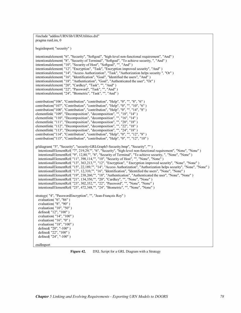
Chapter 5 Linking and Evolving Requirements - Exporting URN Models to DOORS 78
#include "addins/URN/lib/URNUtilities.dxl" pragma runLim, 0 beginImport( "security" ) intentionalelement( "6", "Security", "Softgoal", "high-level non-functional requirement", "And" ) intentionalelement( "8", "Security of Terminal", "Softgoal", "To achieve security, ", "And" ) intentionalelement( "10", "Security of Host", "Softgoal", "", "And" ) intentionalelement( "12", "Encryption", "Task", "Encryption improved security", "And" ) intentionalelement( "14", "Access Authorization", "Task", "Authorization helps security ", "Or" ) intentionalelement( "16", "Identification", "Goal", "Identified the users", "And" ) intentionalelement( "18", "Authentication", "Goal", "Authenticated the user", "Or" ) intentionalelement( "20", "Cardkey", "Task", "", "And" ) intentionalelement( "22", "Password", "Task", "", "And" ) intentionalelement( "24", "Biometric", "Task", "", "And" ) contribution("106", "Contribution", "contribution", "Help", "0", "", "8", "6" ) contribution("107", "Contribution", "contribution", "Help", "0", "", "10", "6" ) contribution("108", "Contribution", "contribution", "Help", "0", "", "14", "8" ) elementlink( "109", "Decomposition", "decomposition", "", "18", "14" ) elementlink( "110", "Decomposition", "decomposition", "", "16", "14" ) elementlink( "111", "Decomposition", "decomposition", "", "20", "18" ) elementlink( "112", "Decomposition", "decomposition", "", "22", "18" ) elementlink( "113", "Decomposition", "decomposition", "", "24", "18" ) contribution("114", "Contribution", "contribution", "Help", "0", "", "12", "8" ) contribution("115", "Contribution", "contribution", "Help", "0", "", "12", "10" ) grldiagram( "5", "Security", "security-GRLGraph5-Security.bmp", "Security", "" ) intentionalElementRef( "7", 219,29,"", "6", "Security", "high-level non-functional requirement", "None", "None" ) intentionalElementRef( "9", 12,80,"", "8", "Security of Terminal", "To achieve security, ", "None", "None" ) intentionalElementRef( "11", 398,114,"", "10", "Security of Host", "", "None", "None" ) intentionalElementRef( "13", 363,213,"", "12", "Encryption", " Encryption improved security", "None", "None" ) intentionalElementRef( "15", 22,189,"", "14", "Access Authorization", "Authorization helps security", "None", "None" ) intentionalElementRef( "17", 12,310,"", "16", "Identification", "Identified the users", "None", "None" ) intentionalElementRef( "19", 238,260,"", "18", "Authentication", "Authenticated the user", "None", "None" ) intentionalElementRef( "21", 134,350,"", "20", "Cardkey", "", "None", "None" ) intentionalElementRef( "23", 302,352,"", "22", "Password", "", "None", "None" ) intentionalElementRef( "25", 472,348,"", "24", "Biometric", "", "None", "None" ) strategy( "4", "PasswordEncryption", "", "Jean-François Roy" ) evaluation( "6", "86" ) evaluation( "8", "90" ) evaluation( "10", "50" ) defined( "12", "100" ) evaluation( "14", "100" ) evaluation( "16", "0" ) evaluation( "18", "100" ) defined( "20", "-100" ) defined( "22", "100" ) defined( "24", "-100" ) endImport
Figure 42. DXL Script for a GRL Diagram with a Strategy

Chapter 5 Linking and Evolving Requirements - Importing URN Model in DOORS 79
5.2 Importing URN Model in DOORS
The DXL scripts generated by jUCMNav can simply be run by DOORS to import the
corresponding URN model. This creates the required formal and link modules for the im-
ported model. In addition, based on the function calls in the scripts, the DOORS objects
and links representing the URN model elements and relationships are created.
5.2.1 DOORS Structure
DOORS is structured using a hierarchy of projects, folders, and modules. URN models
are typically imported into projects that have modules and folders. When a URN model is
imported into a project for the first time, a new folder with the URN model name is cre-
ated, which contains the required formal and link modules. If a folder with the model
name is in the project, the library associates the folder with the URN model.
Responsibilities<<Module>>
Strategies<<Module>>
Maps<<Module>>
Intentional Elements<<Module>>
Intentional Element Associations<<Module>>
GRL Diagrams<<Module>>
Devices<<Module>>
Components<<Module>>
Actors<<Module>>
Scenario<<Module>> URNModelName
<<Folder>>
Figure 43. High-Level View of URN Structure in DOORS
Figure 43 shows the structure of the imported model. Various formal modules are created
in the root folder. UCM is supported through the Maps, Responsibilities, Components,
Devices, and Scenario modules. GRL is supported using five modules: GRL Diagrams,
Intentional Elements, Intentional Element Associations, Actors and Strategies.
Definitions are stored in their own modules. Thus, intentional element and actor
objects are stored respectively in the Intentional Elements and Actors modules. As shown

Chapter 5 Linking and Evolving Requirements - Importing URN Model in DOORS 80
in Figure 44, links between intentional elements are represented using three object types,
corresponding to the association types. These objects have incoming and outgoing links
to their source and destination intentional elements.
The GRL Diagrams module contains all the diagrams and their associate sub-
objects (i.e. intentional element/actor references and beliefs). Reference objects in this
module are created with links to their definition objects. In addition, beliefs can be asso-
ciated to intentional element references. This association is represented using a link from
belief objects to intentional element reference objects. To manage actor bindings, links
are created from bound elements to their actor references. Finally, the Strategies module
contains a list of the GRL strategies and their evaluations for each intentional ele-
ment/actor definition.
Figure 44. Metamodel of GRL in DOORS
For each module, DOORS views are created. These views define visual attributes of the
module, such as the position on the screen and the size of the window, but they also con-
tain the list of attributes to show for the objects. The modules have common views such
as full view and standard view, which show all the imported attributes in a module. In
addition, there are model management views, such as “Deleted View” and “Suspect
Actors<<Module>>
URNModelName<<Folder>>
Actor
0..*0..*
Intentional Elements<<Module>>
GRL Diagrams<<Module>>
GRL Diagram
0..*0..*
Belief
0..*0..*
IntentionalElementRef
0..*0..*
0..*
rationales
0..*
ActorRef
0..*
references
0..*0..*0..*
0..10..*bound to0..10..*0..1
0..*
bound to
0..10..*
0..1
0..*0..*
bound to0..1
refinesrefines
refines
Intentional Element Associations<<Module>>
Decomposition
0..*0..*
Dependency0..*0..*
Contribution
0..*0..*
Intentional Element0..*0..*
0..*
references
0..*
0..*refines
0..*0..*
refines
0..*
0..*
refines
0..*0..*refines
0..*
0..*
0..*
refines
0..*
0..*
refines
Strategy
Strategies<<Module>>
0..*

Chapter 5 Linking and Evolving Requirements - Importing URN Model in DOORS 81
View” (discussed in detail in section 5.3). Finally, each object type imported in modules
has its own view, which shows attributes used by this object type. These views are useful
when multiple object types are stored in the same modules, such as the GRL Diagrams
module (contains GRL Diagram, Belief, ActorRef, and IntentionalElementRef objects).
5.2.2 Internal Links
DOORS links allow creating and navigating traceability associations between objects in
formal modules. Links are defined in link modules, and have a source object and a target
object. When an object is the source of a link, this link is called outgoing link for this ob-
ject, whereas an incoming link is a destination link. Even if links have directions, users
can navigate through them in either direction. Navigation has been implemented in
DOORS using triangle icons ( and ) added to the objects visible in the formal mod-
ule. Incoming and outgoing links for objects are accessed using these icons.
When dividing the URN model into modules, it becomes necessary to define
traceability links to capture internal associations in the model, which we call internal
links. They are created and updated automatically by the DXL library when a URN
model is imported. In the library, once all formal module elements are created or updated,
link instances are created. The link modules that are created include the link definitions,
consisting of a list of all the object types that can be linked together as well as the direc-
tion of these links. In addition, the link modules are used to store the instances of the
links.
For URN, there are eight link modules: Bound To, Hosts, Rationales, References,
Refines, Requests, Traced By and URN links. Except for URN links, all the other link
instances are created automatically at the end of the importing process. For URN links,
they are created by DXL scripts generated in jUCMNav.
The internal links are created bottom-up, starting for a lower-level elements to a
higher-level one. For example, an intentional element reference has two outgoing links:
one to the diagram and another to the intentional element definition.
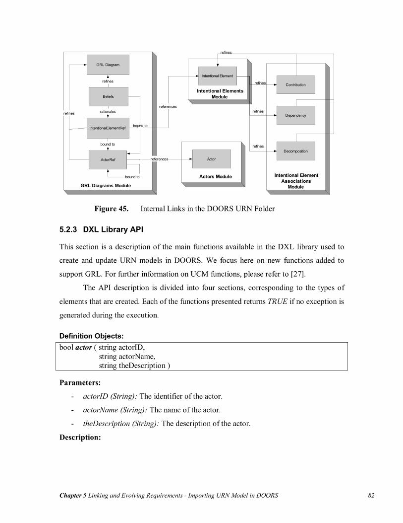
Chapter 5 Linking and Evolving Requirements - Importing URN Model in DOORS 82
GRL Diagrams Module
GRL Diagram
Beliefs
IntentionalElementRef
ActorRef
refines
refines
bound to
bound to
bound to
rationales
Intentional ElementsModule
Intentional Element
references
Actors Module
Actorreferences
Intentional ElementAssociations
Module
Contribution
Dependency
Decompositionrefines
refines
refines
refines
Figure 45. Internal Links in the DOORS URN Folder
5.2.3 DXL Library API
This section is a description of the main functions available in the DXL library used to
create and update URN models in DOORS. We focus here on new functions added to
support GRL. For further information on UCM functions, please refer to [27].
The API description is divided into four sections, corresponding to the types of
elements that are created. Each of the functions presented returns TRUE if no exception is
generated during the execution.
Definition Objects: bool actor ( string actorID, string actorName, string theDescription )
Parameters:
- actorID (String): The identifier of the actor.
- actorName (String): The name of the actor.
- theDescription (String): The description of the actor.
Description:

Chapter 5 Linking and Evolving Requirements - Importing URN Model in DOORS 83
This function creates and updates an actor object in the actors module. The key attribute
for the module is actorID, which uniquely identifies the object. Other parameters corre-
spond to attributes of the actor object.
bool intentionalelement ( string elementID, string elementName, string elementType, string theDescription, string decompositionType )
Parameters:
- elementID (String): The identifier of the intentional element.
- elementName (String): The name of the intentional element.
- elementType (String): The type of the element (softgoal, goal, task or resource).
- theDescription (String): The description of the element.
- decompositionType (String): The type of decomposition of the element (or, and).
Description:
This function creates and updates an intentional element object in the intentional ele-
ments module. The key attribute for the module is elementID, which uniquely identifies
the object. Other parameters correspond to attributes of the intentional element object.
The decompositionType parameter is used to describe the decomposition links associated
to the object.
bool elementlink ( string linkID, string linkName, string linkType, string theDescription, string sourceID, string destinationID )
Parameters:
- linkID (String): The identifier of the element link.
- linkName (String): The name of the element link.
- linkType (String): The type of the link (dependency or decomposition).
- theDescription (String): The description of the element link.
- sourceID (String): Reference to identifier of the source intentional element.
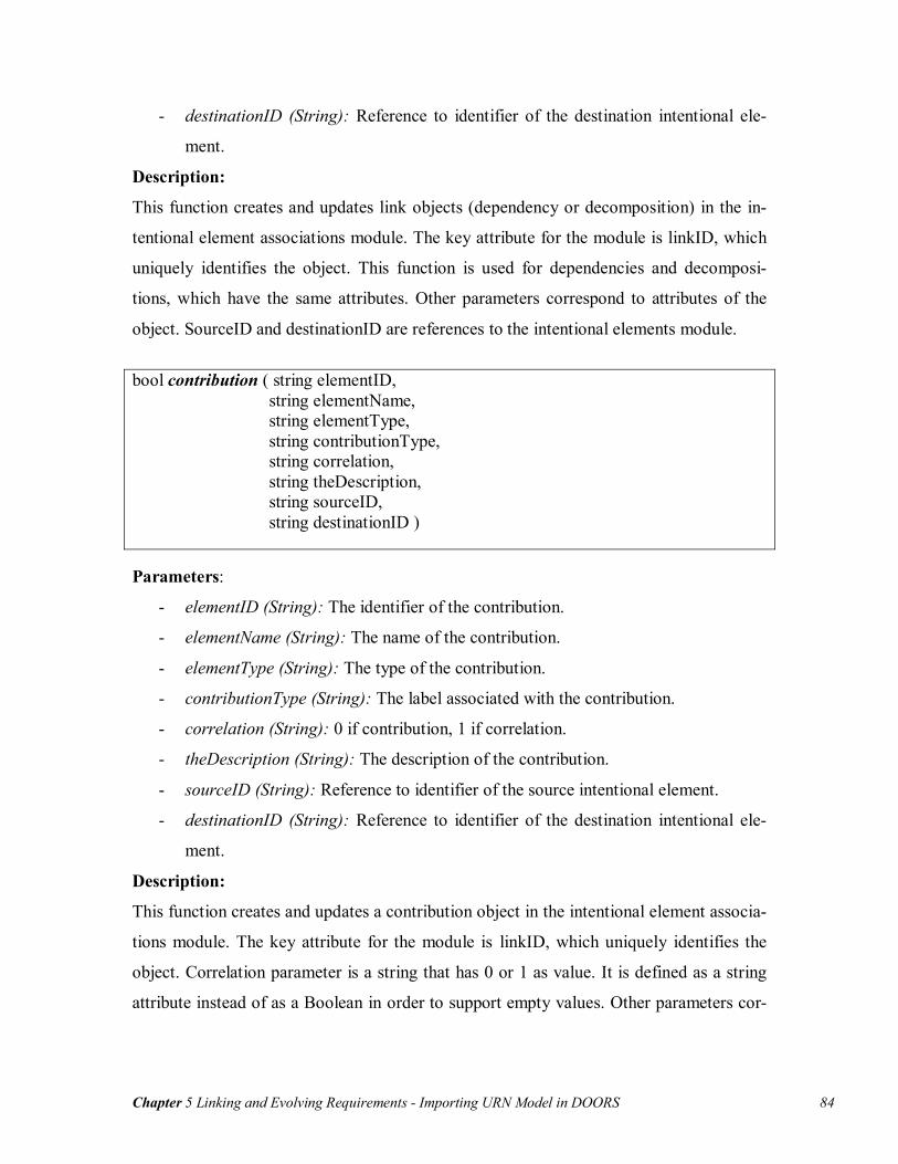
Chapter 5 Linking and Evolving Requirements - Importing URN Model in DOORS 84
- destinationID (String): Reference to identifier of the destination intentional ele-
ment.
Description:
This function creates and updates link objects (dependency or decomposition) in the in-
tentional element associations module. The key attribute for the module is linkID, which
uniquely identifies the object. This function is used for dependencies and decomposi-
tions, which have the same attributes. Other parameters correspond to attributes of the
object. SourceID and destinationID are references to the intentional elements module.
bool contribution ( string elementID, string elementName, string elementType, string contributionType, string correlation, string theDescription, string sourceID, string destinationID )
Parameters:
- elementID (String): The identifier of the contribution.
- elementName (String): The name of the contribution.
- elementType (String): The type of the contribution.
- contributionType (String): The label associated with the contribution.
- correlation (String): 0 if contribution, 1 if correlation.
- theDescription (String): The description of the contribution.
- sourceID (String): Reference to identifier of the source intentional element.
- destinationID (String): Reference to identifier of the destination intentional ele-
ment.
Description:
This function creates and updates a contribution object in the intentional element associa-
tions module. The key attribute for the module is linkID, which uniquely identifies the
object. Correlation parameter is a string that has 0 or 1 as value. It is defined as a string
attribute instead of as a Boolean in order to support empty values. Other parameters cor-

Chapter 5 Linking and Evolving Requirements - Importing URN Model in DOORS 85
respond to attributes of the object. SourceID and destinationID are references to the in-
tentional elements module.
Example:
The following example uses the Web application model developed in preceding chapters.
Figure 46 shows the intentional elements and the intentional element associations mod-
ules. The Standard View is used in these two modules, which displays all the imported
attributes. The figure shows a link from an intentional element to a contribution (id 106 in
the second module).
GRL links are stored in a formal module to allow creating links with external ob-
jects in DOORS. In addition, having the links in a formal module allows for their simple
visualization. It would have been possible to store links in a link module. However, the
traceability analysis for such structure would have missed some attributes that have an
influence on the model.
Figure 46. Intentional Elements and Intentional Element Associations Modules
GRL Diagrams: bool grldiagram ( string modelID, string modelName, string graphFileName, string title, string theDescription )

Chapter 5 Linking and Evolving Requirements - Importing URN Model in DOORS 86
Parameters:
- modelID (String): The identifier of the diagram.
- modelName (String): The name of the diagram.
- graphFileName (String): The diagram image file name.
- title (String): The diagram title.
- theDescription (String): The description of the element.
Description:
This function creates and updates a GRL diagram in the GRL diagrams module. The key
attribute for the module is modelID, which uniquely identifies the object. This function
contains a reference to an image file (bitmap). The graphFileName represents the name of
this file, which shall be stored in the same folder as the executed DXL script. Other pa-
rameters correspond to attributes of the object.
bool actorRef ( string actorRefID, int fx, int fy, int width, int height, string referencedActor, string name, string parentActor )
Parameters:
- actorRefID (String): The identifier of the actor reference.
- fx (int): The x position of the actor reference in the diagram.
- fy (int): The y position of the actor reference in the diagram.
- width (int): The width of the actor reference in the diagram.
- height (int): The height of the actor reference in the diagram.
- referencedActor (String): The identifier of the actor definition.
- name (String): The name of the actor reference.
- parentActor (String): The identifier of the parent actor reference (if any).
Description:
This function creates and updates an actor reference in the GRL diagrams module. It is
created as a sub-object of the latest created/updated GRL diagram object. The key attrib-

Chapter 5 Linking and Evolving Requirements - Importing URN Model in DOORS 87
ute for the module is actorRefID, which uniquely identifies the object. Other parameters
correspond to attributes of the object. The referencedActor is used to create a link to an
actor definition (in the actors module). The parentActor attribute is used to create a link
to the actor reference on which the object is bound (if any).
bool intentionalElementRef ( string refID, int fx, int fy, string enclosingActor, string defID, string name, string theDescription, string priority, string criticality)
Parameters:
- refID (String): The identifier of the intentional element reference.
- fx (int): The x position of the element reference in the diagram.
- fy (int): The y position of the element reference in the diagram.
- enclosingActor (String): The identifier of the parent actor reference (if any).
- defID (String): The identifier of the definition.
- name (String): The name of the intentional element.
- theDescription (String): The description of the intentional element.
- priority (String): The priority of the reference.
- criticality (String): The criticality of the reference.
Description:
This function creates and updates an intentional element reference in the GRL diagrams
module. It is created as a sub-object of the latest created/updated GRL diagram object.
The key attribute for the module is refID, which uniquely identifies the object. Other pa-
rameters correspond to attributes of the object. The defID is used to create a link to the
intentional element definition (in intentional elements module) and the enclosingActor is
used to create a link to the actor reference on which it is bound (if any).

Chapter 5 Linking and Evolving Requirements - Importing URN Model in DOORS 88
bool belief ( string id, int fx, int fy, string enclosingActor, string linkElementId, string name, string theDescription, string author)
Parameters:
- id (String): The identifier of the belief.
- fx (int): The x position of the belief in the diagram.
- fy (int): The y position of the belief in the diagram.
- enclosingActor (String): The identifier of the parent actor reference (if any).
- linkElementId (String): The identifier of the intentional element on which the be-
lief is linked (if any).
- name (String): The name of the belief.
- theDescription (String): The description of the belief.
- author (String): The author of the belief.
Description:
This function creates and updates a belief in the GRL diagrams module. It is created as a
sub-object of the latest created/updated GRL diagram object. The key attribute for the
module is id, which uniquely identifies the object. Other parameters correspond to attrib-
utes of the object. The enclosingActor is used to create a link to the actor reference on
which it is bound (if any) and linkElementId to create link to the intentional element ref-
erence on which it is associate (if any).
Example:
The GRL diagrams module contains multiple object types. Each type has common and
specific attributes. Using the views, it is possible to show only the attributes used by a
specific object type.
Figure 47 shows the structure of the elements in a diagram. References and beliefs
are a subset of a diagram. Thus, they are identified using a number under the diagram. In
addition, internal links are created between the diagram elements and their parents (using

Chapter 5 Linking and Evolving Requirements - Importing URN Model in DOORS 89
the Refines link module). The diagram objects also store the images in their main attrib-
utes.
Figure 47. GRL Diagrams Module
GRL Strategies: bool strategy ( string elementID, string elementName, string theDescription, string author )
Parameters:
- elementID (String): The identifier of the strategy.
- elementName (String): The name of the strategy.
- theDescription (String): The description of the strategy.
- author (String): The author of the strategy
Description:
This function creates and updates a strategy in the Strategies module. The key attribute
for the module is elementID, which uniquely identifies the object. Other parameters cor-
respond to attributes of the object.

Chapter 5 Linking and Evolving Requirements - Importing URN Model in DOORS 90
bool evaluation ( string name,
string value )
Parameters:
- name (String): The name of the intentional element.
- value(String): The value of the evaluation for the intentional element.
Description:
This function creates and updates an evaluation for the latest created/updated strategy.
The name corresponds to an intentional element or actor id, which is set as an attribute. If
the attribute does not exist, it is created. Then, the value parameter is set for this attribute,
which corresponds to the evaluation.
bool defined ( string name, string value )
Parameters:
- name (String): The name of the intentional element.
- value(String): The value of the evaluation for the intentional element.
Description:
This function creates and updates a user-defined evaluation for the latest created/updated
strategy. It is implemented as the evaluation function, but a star (*) is added at the end of
the evaluation value (to distinguish user-defined evaluations from calculated evaluations
in the module).
Example:
All the strategies from the Web application case study were exported to DOORS.
Figure 48 shows the resulting formal module. Rows define the different strategies avail-
able in the model and columns correspond to identifiers of the elements used in the strate-
gies (actor and intentional element definitions).
The Strategies module can be implemented using two alternatives: using strate-
gies or using element ids as the objects. Using element ids has the advantage of allowing
the creation of internal links between the elements and their definitions. However, the
strategies option encapsulates the dynamic behaviour of the GRL model, which can be
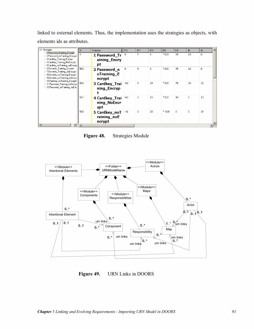
Chapter 5 Linking and Evolving Requirements - Importing URN Model in DOORS 91
linked to external elements. Thus, the implementation uses the strategies as objects, with
elements ids as attributes.
Figure 48. Strategies Module
Actors<<Module>>
Intentional Elements<<Module>>
Maps<<Module>>
URNModelName<<Folder>>
Components<<Module>>
Responsibilities<<Module>>
Actor
0..*0..*
Component
0..*0..*
0..*
0..1
urn links0..*
0..1
Responsibility
0..*0..*
0..*
0..1
urn links
0..*
0..1Intentional Element
0..*0..*
0..*0..1urn links
0..*0..1
0..*
0..1
urn links0..*
0..1
Map
0..* 0..*
0..1
urn links0..*
0..1
0..*
0..10..1
urn links0..*
Figure 49. URN Links in DOORS

Chapter 5 Linking and Evolving Requirements - Using URN Models in DOORS 92
URN Links:
bool urnlink ( string sourceID, string destinationID )
Parameters:
- sourceID (String): The identifier of the link source.
- destinationID (String): The identifier of the link destination.
Description:
This function creates and updates URN links from a source element to a destination ele-
ment. These links are created in the urn links module (DOORS link module). The links
are created from GRL elements to UCM elements, as supported in jUCMNav. The struc-
ture of URN links in DOORS is shown in Figure 49.
5.3 Using URN Models in DOORS
This section presents how to use imported URN models in DOORS. Linking URN mod-
els to external requirements is required to support parallel evolution of the URN model
and of the requirements. The suggested strategy to create the links is presented. Then, a
description of the updating mechanism is described, focusing on traceability analysis and
synchronizations of URN and requirements.
5.3.1 Linking to DOORS
URN models and textual requirements are complementary artefacts. URN models are
created using objectives, goals, and user requirements. The functional requirements guide
the creation of the UCM sub-view while non-functional requirements help developing the
GRL sub-view. However, URN models also help discovering lower-level requirements.
In addition, the analysis mechanisms allow questioning the requirements. Thus, the de-
velopment of URN models and requirements is an iterative process.
Importing URN in a RMS allows generating traceability links between the two
types of artefacts, and managing the evolution of requirements and models. The preced-
ing sections demonstrated how to import URN models into DOORS. Once the first ver-
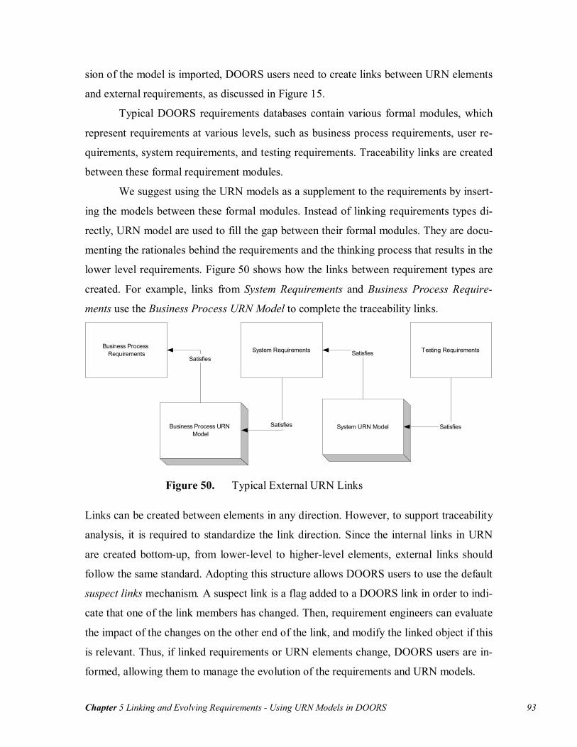
Chapter 5 Linking and Evolving Requirements - Using URN Models in DOORS 93
sion of the model is imported, DOORS users need to create links between URN elements
and external requirements, as discussed in Figure 15.
Typical DOORS requirements databases contain various formal modules, which
represent requirements at various levels, such as business process requirements, user re-
quirements, system requirements, and testing requirements. Traceability links are created
between these formal requirement modules.
We suggest using the URN models as a supplement to the requirements by insert-
ing the models between these formal modules. Instead of linking requirements types di-
rectly, URN model are used to fill the gap between their formal modules. They are docu-
menting the rationales behind the requirements and the thinking process that results in the
lower level requirements. Figure 50 shows how the links between requirement types are
created. For example, links from System Requirements and Business Process Require-
ments use the Business Process URN Model to complete the traceability links.
Business ProcessRequirements System Requirements
Business Process URNModel
System URN Model
Testing Requirements
Satisfies
Satisfies
Satisfies
Satisfies
Figure 50. Typical External URN Links
Links can be created between elements in any direction. However, to support traceability
analysis, it is required to standardize the link direction. Since the internal links in URN
are created bottom-up, from lower-level to higher-level elements, external links should
follow the same standard. Adopting this structure allows DOORS users to use the default
suspect links mechanism. A suspect link is a flag added to a DOORS link in order to indi-
cate that one of the link members has changed. Then, requirement engineers can evaluate
the impact of the changes on the other end of the link, and modify the linked object if this
is relevant. Thus, if linked requirements or URN elements change, DOORS users are in-
formed, allowing them to manage the evolution of the requirements and URN models.
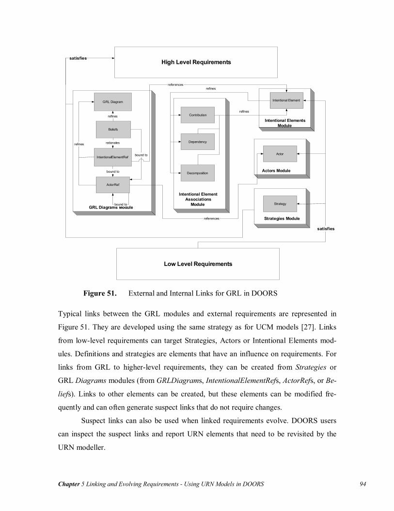
Chapter 5 Linking and Evolving Requirements - Using URN Models in DOORS 94
GRL Diagrams Module
GRL Diagram
Beliefs
IntentionalElementRef
ActorRef
refines
refines
bound to
bound to
bound to
rationales
Intentional ElementsModule
Intentional Element
references
Actors Module
Actor
references
Intentional ElementAssociations
Module
Contribution
Dependency
Decomposition
refines
refines
Strategy
Strategies Module
Low Level Requirements
High Level Requirements
satisfies
satisfies
Figure 51. External and Internal Links for GRL in DOORS
Typical links between the GRL modules and external requirements are represented in
Figure 51. They are developed using the same strategy as for UCM models [27]. Links
from low-level requirements can target Strategies, Actors or Intentional Elements mod-
ules. Definitions and strategies are elements that have an influence on requirements. For
links from GRL to higher-level requirements, they can be created from Strategies or
GRL Diagrams modules (from GRLDiagrams, IntentionalElementRefs, ActorRefs, or Be-
liefs). Links to other elements can be created, but these elements can be modified fre-
quently and can often generate suspect links that do not require changes.
Suspect links can also be used when linked requirements evolve. DOORS users
can inspect the suspect links and report URN elements that need to be revisited by the
URN modeller.
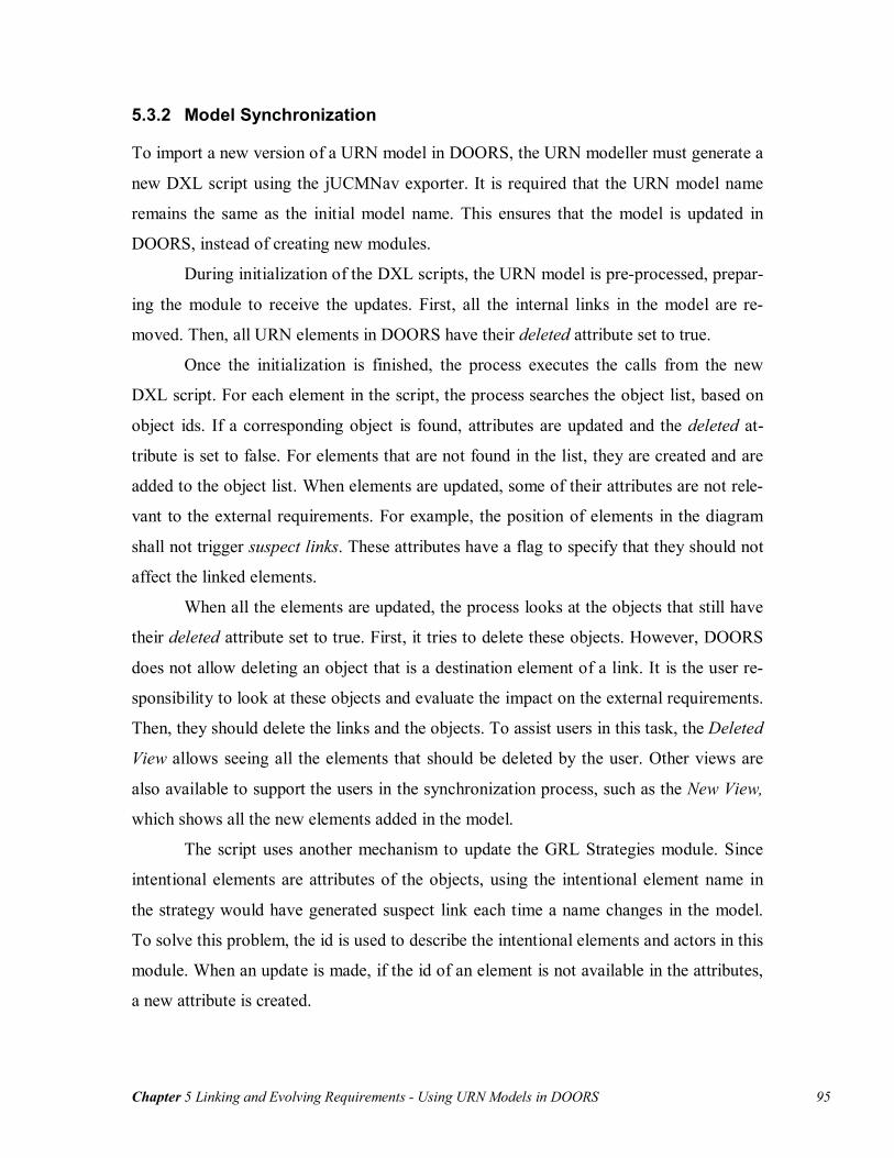
Chapter 5 Linking and Evolving Requirements - Using URN Models in DOORS 95
5.3.2 Model Synchronization
To import a new version of a URN model in DOORS, the URN modeller must generate a
new DXL script using the jUCMNav exporter. It is required that the URN model name
remains the same as the initial model name. This ensures that the model is updated in
DOORS, instead of creating new modules.
During initialization of the DXL scripts, the URN model is pre-processed, prepar-
ing the module to receive the updates. First, all the internal links in the model are re-
moved. Then, all URN elements in DOORS have their deleted attribute set to true.
Once the initialization is finished, the process executes the calls from the new
DXL script. For each element in the script, the process searches the object list, based on
object ids. If a corresponding object is found, attributes are updated and the deleted at-
tribute is set to false. For elements that are not found in the list, they are created and are
added to the object list. When elements are updated, some of their attributes are not rele-
vant to the external requirements. For example, the position of elements in the diagram
shall not trigger suspect links. These attributes have a flag to specify that they should not
affect the linked elements.
When all the elements are updated, the process looks at the objects that still have
their deleted attribute set to true. First, it tries to delete these objects. However, DOORS
does not allow deleting an object that is a destination element of a link. It is the user re-
sponsibility to look at these objects and evaluate the impact on the external requirements.
Then, they should delete the links and the objects. To assist users in this task, the Deleted
View allows seeing all the elements that should be deleted by the user. Other views are
also available to support the users in the synchronization process, such as the New View,
which shows all the new elements added in the model.
The script uses another mechanism to update the GRL Strategies module. Since
intentional elements are attributes of the objects, using the intentional element name in
the strategy would have generated suspect link each time a name changes in the model.
To solve this problem, the id is used to describe the intentional elements and actors in this
module. When an update is made, if the id of an element is not available in the attributes,
a new attribute is created.
Chapter 5 Linking and Evolving Requirements - Chapter Summary 96
The last step of the update process consists of recreating the internal links in the
URN model. This step does not affect the external requirement links because link modifi-
cations are considered by the system as minor updates.
5.4 Chapter Summary
This chapter presented how URN models can be linked to external requirements using a
common RMS. This allows developing complete requirements that also document the
rationale for these requirements. Since requirements can evolve over time, the traceability
mechanism presented allows triggering events when URN models or external require-
ments need to be revisited.
The process for importing URN model is composed of three steps. First, as pre-
sented in Section 5.1, the URN modeller must generate a DXL script from the model. A
utility, the DOORS exporter, is available in jUCMNav to automate this task. Then, as
discussed in Section 5.2, the DOORS user must execute the script. The latter invokes
functions of a DXL API that creates the required modules, objects, and links. Once the
model is imported, DOORS users can create links between the model and external re-
quirements. These links are the main element used for traceability analysis. As detailed in
Section 5.3, the model/requirements evolution can be managed using suspect links, in a
way similar to what was proposed by Jiang et al. [27][37].
The next chapter will demonstrate how to model requirements with jUCMNav
and DOORS, using a more complex case study: a Web credit card gateway.
Chapter 6 Case Study: Credit Card Gateway - Modelling Using URN 97
Chapter 6 Case Study: Credit Card Gateway
This chapter presents a case study that uses the tools and approaches described previ-
ously. The case study is a Web credit card gateway, which contains multiple require-
ments that sometimes conflict, such as security and cost. To model and analyze the re-
quirements, a URN model is developed in jUCMNav, and the analysis mechanisms are
used. Finally, the model is exported to DOORS.
The first section introduces the development of the URN model based on four ar-
chitectures considered for this system. It describes the high-level functional and non-
functional requirements for the system. In section 6.2, we add URN links between ele-
ments in the model, which will show that the model requires further refinement. This re-
finement will be realized using a small GRL catalogue. Then, in section 6.3, the new
jUCMNav analysis features are used to analyze requirements and determine the best ar-
chitectural solution for this case study. The model is also exported to DOORS and linked
to external requirements in section 6.4.
6.1 Modelling Using URN
Despites a large number of e-business Web sites, offering a secure and robust architecture
for credit card payment remains a problem. In this situation, merchants use third party
services such as credit-card gateways, which are services acting as middle-men between
merchants and a bank in order to manage the transactions securely. Credit-card gateways
allow merchants to develop their e-business sites more rapidly, without having to deal
with requirements for credit card processing. However, for this type of service to be suc-
cessful, it shall satisfy the concerns of a large number of stakeholders, such as merchants,
customers, and banks. As suggested by Lamsweerde [31], goal models can guide the se-
lection of a suitable architecture while taking such concerns into account.

Chapter 6 Case Study: Credit Card Gateway - Modelling Using URN 98
6.1.1 Customers-Merchants Modelling
The requirements for a credit card processing service are driven by the customers-
merchants collaborations. Figure 52 shows the buying process between customers and
merchants. This process considers only the situation where the customer has selected
product(s) to buy. Once the merchant requests the payment, the customer enters the pay-
ment information, which corresponds to the payment method (Furnish payment informa-
tion responsibility). If the payment method is credit card, then the merchant uses the
credit card gateway to process the payment, which is modeled in a dynamic stub. Other
payment methods are not considered in this model but could be added to the Process
Payment stub.
Figure 52. Buying Process between Customer and Merchant
A transaction happens between a customer and a merchant to satisfy their goals. The
main goal of the customer is to receive the desired products. However, this goal is satis-
fied only if the merchant provides these products. This relation is modeled as a three-
element dependency, with the customer depending on Products resources, which are pro-
vided by the merchant (Figure 53). A similar dependency is created for the payment. The
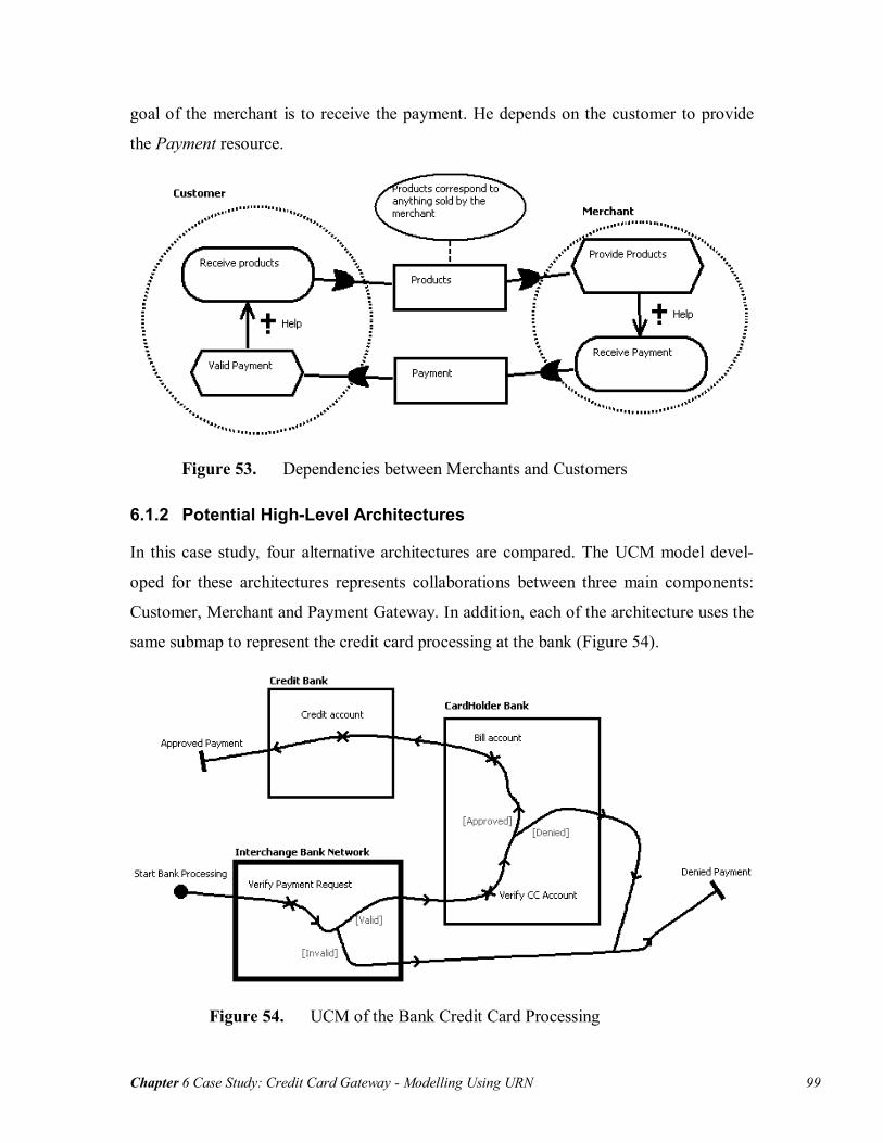
Chapter 6 Case Study: Credit Card Gateway - Modelling Using URN 99
goal of the merchant is to receive the payment. He depends on the customer to provide
the Payment resource.
Figure 53. Dependencies between Merchants and Customers
6.1.2 Potential High-Level Architectures
In this case study, four alternative architectures are compared. The UCM model devel-
oped for these architectures represents collaborations between three main components:
Customer, Merchant and Payment Gateway. In addition, each of the architecture uses the
same submap to represent the credit card processing at the bank (Figure 54).
Figure 54. UCM of the Bank Credit Card Processing

Chapter 6 Case Study: Credit Card Gateway - Modelling Using URN 100
The bank processing map uses three components. First, the Interchange Bank Network is
responsible for verifying the payment request, and forwarding the request to the card-
holder bank if it is valid. Then, the CardHolder Bank verifies the credit card account. If
this account fills all the requirements to accept the payment, it is billed and the request is
forwarded to the Credit Bank. This component is responsible to credit the paid account,
which can be the account of the merchant or the account of the payment gateway, de-
pending on the architecture.
Standard Payment Processing The standard payment processing architecture is the simplest architecture for this type of
service. As shown in Figure 55, the payment form is provided to the user by the mer-
chant. Then, the user enters its credit card information (name, number, expiration date),
and sends the information to the merchant. The merchant adds account and payment in-
formation, and forwards the request to the payment gateway. The gateway verifies the
payment request, and sends it to banks (Bank Processing stub) if it is valid.
Figure 55. Standard Payment Processing UCM
Gateway to Customer Payment Processing This architecture differs from the standard payment processing by moving two responsi-
bilities to the payment gateway: Payment form and Verify payment info. The transaction
starts with the merchant that add it information to the payment request, which is forward

Chapter 6 Case Study: Credit Card Gateway - Modelling Using URN 101
to the payment gateway (Figure 56). In this architecture, only the payment gateway ac-
cesses the credit card information. Limiting access to this critical data reduce security
risks of the transactions.
Figure 56. Gateway to Customer Payment Processing UCM
Third Party Payment Processing In this architecture, customer and merchant shall have registered to the gateway services
prior to the transaction. Once a payment request is sent by the merchant, the customer is
redirected to the payment gateway Website to process the request. As shown in
Figure 57, the user logs in its account, and the gateway manages the access to the credit
card. After the bank has processed the transaction, messages are sent to the customer and
the merchant to inform them of the result of the transaction. This is the approach used by
services such as Paypal [44].
3D Secure Payment Processing The 3D Secure [57] is a standard developed by credit card associations (including VISA
and Mastercard) to support secure transactions and to minimize the requirements placed

Chapter 6 Case Study: Credit Card Gateway - Modelling Using URN 102
on the merchant. This approach requires that the cardholder registers with the system
prior to using his credit card. During the transaction, the merchant has the responsibility
of providing the payment form to the customer, and has access to the credit card informa-
tion. However, for a transaction to be valid, the customer needs to enter his password.
The merchant does not have access to this password, as shown in Figure 58.
Figure 57. Third Party Payment Processing UCM

Chapter 6 Case Study: Credit Card Gateway - Modelling Using URN 103
Figure 58. 3D Payment Processing UCM
6.1.3 GRL Model
The GRL model for this case study captures the concerns of the stakeholders involved in
the system. As shown in Figure 59, cardholder is modeled as a sub-actor of the customer
in order to represent that the cardholder is a customer with additional concerns. Even if
the customer and the cardholder are habitually the same person, the customer is con-
cerned by the products whereas the cardholder is concerned with the payment and secu-
rity. If the cardholder can achieve secure payments, this influences its trust of the mer-
chant (Some Positive). Buying the merchant product is a task which is affected by the sat-
isfaction of the goals of both the customer and the cardholder. This intentional element is
an example of a task that can have a weakly satisfied or weakly denied evaluation.

Chapter 6 Case Study: Credit Card Gateway - Modelling Using URN 104
Figure 59. High-Level Goal Model
Buy Merchant Products highly contributes to the Sell Products goal, which in turn helps
maximize the merchant profits. In addition, minimizing the merchant cost has a positive
impact on the profit. In this model, merchant cost is affected by two softgoals (Cost of
Products and Minimize Cost of Web Site). However, other elements impact the merchant
cost, which are not considered in this case study. The cost of the payment gateway has an
impact on the cost of the merchant’s Web site. In addition, this concern is bound to the
payment gateway, because highly expensive services will not be adopted by the mer-
chants. To be able to minimize the service cost, payment gateway shall minimize the sys-
tem implementation cost.
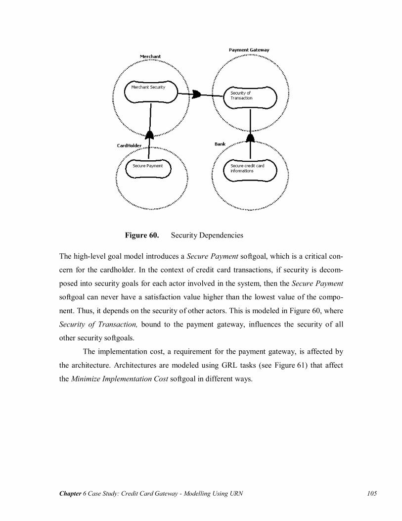
Chapter 6 Case Study: Credit Card Gateway - Modelling Using URN 105
Figure 60. Security Dependencies
The high-level goal model introduces a Secure Payment softgoal, which is a critical con-
cern for the cardholder. In the context of credit card transactions, if security is decom-
posed into security goals for each actor involved in the system, then the Secure Payment
softgoal can never have a satisfaction value higher than the lowest value of the compo-
nent. Thus, it depends on the security of other actors. This is modeled in Figure 60, where
Security of Transaction, bound to the payment gateway, influences the security of all
other security softgoals.
The implementation cost, a requirement for the payment gateway, is affected by
the architecture. Architectures are modeled using GRL tasks (see Figure 61) that affect
the Minimize Implementation Cost softgoal in different ways.

Chapter 6 Case Study: Credit Card Gateway - Evolving the Credit Card Gateway Model 106
Figure 61. Implementation Cost Model
The URN diagrams shown here were developed using the new jUCMNav. Using addi-
tional features of our tool, it is now possible to refine the model and better reflect the re-
quirements.
6.2 Evolving the Credit Card Gateway Model
In this section, to support the integration of both URN sub-notations, URN links are
added to the model. These links enable the analysis of the model and the discovery of lo-
cations where the model shall be further refined. Then, using a GRL catalogue, new in-
tentional elements are added and integrated to the URN model.
6.2.1 Creating URN Links
Adding URN links allows supporting traceability between UCM and GRL elements.
Then, when the model evolves, it becomes possible to evaluate the impact of changes on
linked elements. The URN links can be developed at the same time as the model.
In the model, links are added between actors and components. The actors in GRL
correspond to stakeholders involved in the process, often shown as components in UCMs.
Thus, links are created between actors Customer, Merchant and Payment Gateway and

Chapter 6 Case Study: Credit Card Gateway - Evolving the Credit Card Gateway Model 107
UCM components Customer, Merchant, and Payment Gateway, respectively. Note that in
the UCM model, no distinction is made between customer and cardholder. In this situa-
tion, we used the parent actor of cardholder (customer) to create the links. Links are also
created between the Bank actor and the corresponding UCM components (Interchange
Bank Network, CardHolder Bank and Credit Bank).
The architecture tasks can also be linked to their corresponding plug-in maps in
the UCM view. However, no links can be made at this point between intentional elements
and responsibilities. Some of the responsibilities have an influence on the satisfaction of
intentional elements. Therefore, further refinement of the GRL model is required.
6.2.2 Adding a Secure Transaction Catalogue
GRL catalogues allow reusing models previously developed. In the credit card gateway
case study, we are using a small catalogue to model transaction security. This catalogue,
which can be used in any context that has transactions, describes high-level softgoals that
should be satisfied to achieve security of transactions. Figure 62 shows the catalogue,
where the main concern is to achieve secure transactions by satisfying integrity and non-
repudiation of the information. Integrity corresponds to the quality of transactions where
information cannot be altered by an unauthorized party without being detected. Non-
repudiation of transaction ensures that the sender and receiver involved are the parties
they claim to be. Authentication is a softgoal that helps achieving non-repudiation. Fi-
nally, confidentiality influences positively the security of transactions.
When the catalogue is imported in the URN model, a new GRL diagram is cre-
ated with the imported elements. To integrate it with the model, intentional elements that
are the same in the catalogue and the model should use the same element definition. Dur-
ing the import process, when the name of an imported element is the same name as one of
the elements in the model (name clash), a suffix is added to the name (i.e. Security of
Transaction is renamed Security of Transaction2). In the case study, we change the inten-
tional element reference of Security of Transaction to the definition used in Figure 60.

Chapter 6 Case Study: Credit Card Gateway - Evolving the Credit Card Gateway Model 108
Figure 62. GRL Model of the Security of Transaction Catalogue
Once the catalogue is integrated with the model, the security model is refined to adapt it
to the context of the credit card gateway (Figure 63). If the main security goal is satisfied
(on which depend the security of cardholders, merchants, and banks, as described in
Figure 60), this would help satisfying three other goals: Receive Payment, Receive Prod-
ucts and Trust. These associations are modeled as correlations because they are side-
effects.
The Authentication goal is decomposable for each party involved in the transac-
tion, i.e. cardholder and merchant. The authentication of the parties is hard to satisfy.
However, using certificates helps authenticate the actors. In addition, the architectures
that are using a password to identify cardholders (3D Secure and Third Party) help au-
thenticate these cardholders. Integrity can also be decomposed into Payment Data Integ-
rity and Credit Card Information Integrity. In this case study, the only method proposed
to achieve integrity is encryption (modeled as a task). Finally, some of the architectures
allow merchants to access credit card information. This is a security risk affecting the
credit card information integrity and confidentiality (Some Negative for Credit Card In-
formation Integrity and Hurt for Confidentiality).
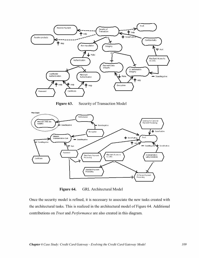
Chapter 6 Case Study: Credit Card Gateway - Evolving the Credit Card Gateway Model 109
Figure 63. Security of Transaction Model
Figure 64. GRL Architectural Model
Once the security model is refined, it is necessary to associate the new tasks created with
the architectural tasks. This is realized in the architectural model of Figure 64. Additional
contributions on Trust and Performance are also created in this diagram.
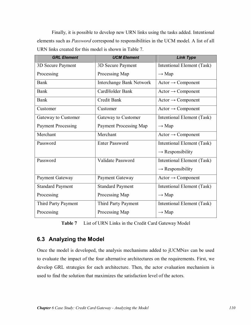
Chapter 6 Case Study: Credit Card Gateway - Analyzing the Model 110
Finally, it is possible to develop new URN links using the tasks added. Intentional
elements such as Password correspond to responsibilities in the UCM model. A list of all
URN links created for this model is shown in Table 7. GRL Element UCM Element Link Type
3D Secure Payment
Processing
3D Secure Payment
Processing Map
Intentional Element (Task)
→ Map
Bank Interchange Bank Network Actor → Component
Bank CardHolder Bank Actor → Component
Bank Credit Bank Actor → Component
Customer Customer Actor → Component
Gateway to Customer
Payment Processing
Gateway to Customer
Payment Processing Map
Intentional Element (Task)
→ Map
Merchant Merchant Actor → Component
Password Enter Password Intentional Element (Task)
→ Responsibility
Password Validate Password Intentional Element (Task)
→ Responsibility
Payment Gateway Payment Gateway Actor → Component
Standard Payment
Processing
Standard Payment
Processing Map
Intentional Element (Task)
→ Map
Third Party Payment
Processing
Third Party Payment
Processing Map
Intentional Element (Task)
→ Map
Table 7 List of URN Links in the Credit Card Gateway Model
6.3 Analyzing the Model
Once the model is developed, the analysis mechanisms added to jUCMNav can be used
to evaluate the impact of the four alternative architectures on the requirements. First, we
develop GRL strategies for each architecture. Then, the actor evaluation mechanism is
used to find the solution that maximizes the satisfaction level of the actors.

Chapter 6 Case Study: Credit Card Gateway - Analyzing the Model 111
6.3.1 Evaluation of Intentional Elements
To achieve a useful comparison of the architectures, it is necessary to determine the
variation points in the model. These variation points are intentional elements, usually
tasks, which have user-defined evaluations in the GRL strategies. In this case study, we
are comparing four architectures, which are the elements that should have user-defined
evaluations. In addition, these architectures are mutually exclusives. The impact of en-
cryption and certificate on the requirements is also interesting to evaluate. The usage of
these elements should be combined with the architectures.
The strategies are structured using groups for each of the architectures. Strategies
with certificate and encryption and strategies without certificate and encryption are cre-
ated. Table 8 shows the impact of strategies on the high-level intentional elements. The
result of the strategies does not allow making a decision on which architecture to use.
Some of the intentional element evaluations are opposite. For example, if we want to
minimize the implementation cost, the standard payment architecture with encryption and
certificate is the best solution but it is the worst solution for security of transactions.
Therefore, further analysis of the model is required.
6.3.2 Evaluation of Actors
To maximize the actors’ satisfaction levels, it is required to add criticality and priority to
the intentional elements bound to actors. By default, these values are set to none, which
result in satisfaction labels of 0 for actors.
Table 9 shows the priorities and criticalities assigned to the intentional element
references (note that the table shows only references that have an assigned priority or
criticality). Elements that have multiple references can have different priorities and criti-
calities for their actors. For instance, the Merchant Web Site Usability softgoal is bound
to Customer (low priority and no criticality) and to Merchant (medium priority and me-
dium criticality).
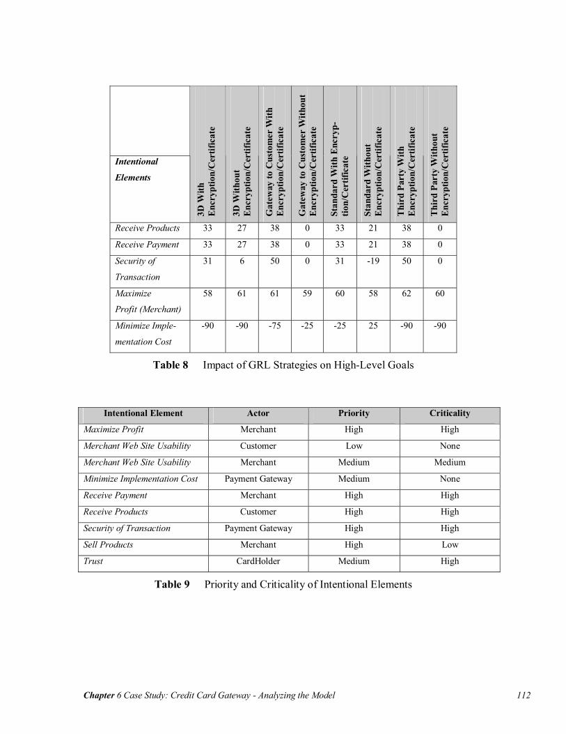
Chapter 6 Case Study: Credit Card Gateway - Analyzing the Model 112
Intentional
Elements
3D W
ith
Enc
rypt
ion/
Cer
tific
ate
3D W
ithou
t E
ncry
ptio
n/C
ertif
icat
e
Gat
eway
to C
usto
mer
With
E
ncry
ptio
n/C
ertif
icat
e
Gat
eway
to C
usto
mer
With
out
Enc
rypt
ion/
Cer
tific
ate
Stan
dard
With
Enc
ryp-
tion/
Cer
tific
ate
Stan
dard
With
out
Enc
rypt
ion/
Cer
tific
ate
Thi
rd P
arty
With
E
ncry
ptio
n/C
ertif
icat
e
Thi
rd P
arty
With
out
Enc
rypt
ion/
Cer
tific
ate
Receive Products 33 27 38 0 33 21 38 0
Receive Payment 33 27 38 0 33 21 38 0
Security of
Transaction
31 6 50 0 31 -19 50 0
Maximize
Profit (Merchant)
58
61 61 59 60 58 62 60
Minimize Imple-
mentation Cost
-90 -90 -75 -25 -25 25 -90 -90
Table 8 Impact of GRL Strategies on High-Level Goals
Intentional Element Actor Priority Criticality
Maximize Profit Merchant High High
Merchant Web Site Usability Customer Low None
Merchant Web Site Usability Merchant Medium Medium
Minimize Implementation Cost Payment Gateway Medium None
Receive Payment Merchant High High
Receive Products Customer High High
Security of Transaction Payment Gateway High High
Sell Products Merchant High Low
Trust CardHolder Medium High
Table 9 Priority and Criticality of Intentional Elements

Chapter 6 Case Study: Credit Card Gateway - Managing Requirements in DOORS 113
Actors
3D W
ith
Enc
rypt
ion/
Cer
tific
ate
3D W
ithou
t E
ncry
ptio
n/C
ertif
icat
e
Gat
eway
to C
usto
mer
With
E
ncry
ptio
n/C
ertif
icat
e
Gat
eway
to C
usto
mer
With
out
Enc
rypt
ion/
Cer
tific
ate
Stan
dard
With
Enc
ryp-
tion/
Cer
tific
ate
Stan
dard
With
out
Enc
rypt
ion/
Cer
tific
ate
Thi
rd P
arty
With
E
ncry
ptio
n/C
ertif
icat
e
Thi
rd P
arty
With
out
Enc
rypt
ion/
Cer
tific
ate
CardHolder 72 65 78 31 10 7 100 93
Customer 31 25 36 0 31 21 36 0
Merchant 53 53 57 41 53 48 57 43
Payment Gateway 1 -24 25 -8 22 -10 20 -30
Table 10 Impact of GRL Strategies on Actors
Using the priority and criticality for intentional element references bound to actors, actor
satisfaction levels are calculated. Table 10 shows the result for each strategy. Based on
this evaluation, two architectures generate highly positive evaluations for each actor:
Gateway to Customer and Third Party payment processing architecture (both with en-
cryption and certificate). However, even if cardholder is fully satisfied with the third
party architecture (evaluation of 100), the payment gateway is considered the actor with
the highest importance because this is the actor representing the system to be developed.
If its concerns are not satisfied, then there is no reason to develop the system. Hence, we
select the Gateway to Customer architecture and preserve the model with strategies to
document the rationale behind this major design decision.
6.4 Managing Requirements in DOORS
In this section, the URN model is imported into DOORS. Then, links to external objects
are created. Using these external objects and links, modifications to the URN model are
performed and the latter is re-imported into DOORS. Finally, we describe the impact of
the modifications on the DOORS database.
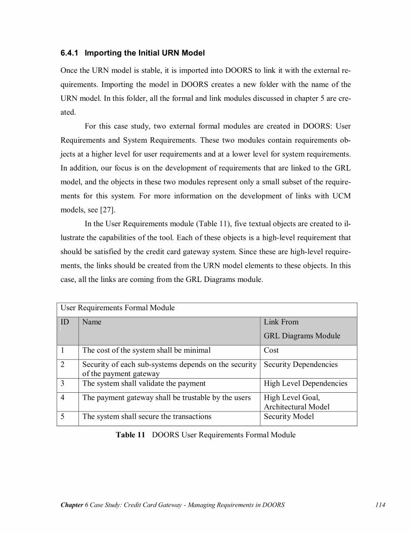
Chapter 6 Case Study: Credit Card Gateway - Managing Requirements in DOORS 114
6.4.1 Importing the Initial URN Model
Once the URN model is stable, it is imported into DOORS to link it with the external re-
quirements. Importing the model in DOORS creates a new folder with the name of the
URN model. In this folder, all the formal and link modules discussed in chapter 5 are cre-
ated.
For this case study, two external formal modules are created in DOORS: User
Requirements and System Requirements. These two modules contain requirements ob-
jects at a higher level for user requirements and at a lower level for system requirements.
In addition, our focus is on the development of requirements that are linked to the GRL
model, and the objects in these two modules represent only a small subset of the require-
ments for this system. For more information on the development of links with UCM
models, see [27].
In the User Requirements module (Table 11), five textual objects are created to il-
lustrate the capabilities of the tool. Each of these objects is a high-level requirement that
should be satisfied by the credit card gateway system. Since these are high-level require-
ments, the links should be created from the URN model elements to these objects. In this
case, all the links are coming from the GRL Diagrams module.
User Requirements Formal Module
ID Name Link From
GRL Diagrams Module
1 The cost of the system shall be minimal Cost
2 Security of each sub-systems depends on the security of the payment gateway
Security Dependencies
3 The system shall validate the payment High Level Dependencies
4 The payment gateway shall be trustable by the users High Level Goal, Architectural Model
5 The system shall secure the transactions Security Model
Table 11 DOORS User Requirements Formal Module

Chapter 6 Case Study: Credit Card Gateway - Managing Requirements in DOORS 115
The same approach is used for the System Requirements module (Table 12). The links in
this module are from its objects to the URN elements. We create links to three types of
elements in URN: actor definitions, intentional element definitions, and GRL strategies.
System Requirements Formal Module
ID Name Link To
1 The system shall minimize the cost of using the service for the merchant
- Merchant (Actor) - Minimize Cost of Web Site
(Element)
2 The system architecture shall not allow mer-chants to access credit card numbers
- Merchant (Actor) - Merchant Access to CC Info (Element)
3 The credit card gateway service cost shall be lower than cost for the merchant to implement a payment system.
- Payment Gateway (Actor) - Minimize Service Cost (Ele-
ment) 4 The credit card processing shall have good per-
formance
- Payment Gateway (Actor) - Performance (Element)
5 The system should not affect the usability of the merchant Web site
- Merchant (Actor) - Merchant Web Site Usability
(Element)
6 The credit card transaction shall be secure
- Gateway to Customer With Encryption /Certificate (Strategy)
6.1 The system shall use certificate - Certificate (Element)
6.2 The system shall use encryption - Encryption (Element)
6.3 The system shall manage the data to ensure confidentiality
- Confidentiality (Element)
6.4 The system shall use authentication methods - Authentication (Element)
Table 12 DOORS System Requirements Formal Module
6.4.2 Updating a URN Model in DOORS
Using the links developed in the previous section, we modify the URN model in jUCM-
Nav to evaluate the impact of each type of modification on the DOORS objects. The
modifications that have an impact on the higher-level objects are adding, modifying and
deleting GRL diagrams. The modifications that have an impact on the lower-level ele-

Chapter 6 Case Study: Credit Card Gateway - Managing Requirements in DOORS 116
ments are adding, modifying and deleting actors, intentional elements, and strategies. The
purpose of these updates is to test that all combinations are supported correctly in our
tool.
GRL Diagrams Description of the changes:
• Delete diagram Cost
• Add architectural tasks and link references to Minimize Implementation Cost
in High Level Goals diagram
• Add new diagram calls Usability who has references to Merchant Web Site
Usability, Service Usability softgoals, architectural tasks and new contribu-
tions.
DOORS Views:
• New intentional element references in High Level Goal diagram are displayed
in the New Object view. These changes are not generating suspect links be-
cause only one link has been defined from the diagram object. Changes on
elements in the diagram are not considered significant changes (significant
changes correspond to attribute modifications).
• Usability diagram, new actor references and new intentional element refer-
ences are shown in the New Object view.
• Cost diagram is displayed in the Deleted view. DOORS user should delete
manually the outgoing link before the object can be deleted. References in this
diagram are deleted automatically.
Actors Description of the changes:
• Add actor Web Developers
• Change Payment Gateway name and description
• Delete Bank Actor
Results in DOORS:
• Web Developers actor is displayed in New Object View.
Chapter 6 Case Study: Credit Card Gateway - Chapter Summary 117
• Bank actor is deleted (objects with incoming links are deleted automatically).
• Suspect incoming link to Payment Gateway.
Intentional Elements Description of the changes:
• Add Service Usability softgoal
• Modify Need Products type (from goal to softgoal)
• Delete Cost of Products softgoal
Results in DOORS:
• Service Usability shows in New Object View.
• Cost of Products is deleted.
• Suspect incoming link for Need Products
GRL Strategies Description of the changes:
• Modification of the attributes (intentional elements and actors)
Results in DOORS:
• Suspect incoming link to strategy: Gateway to Customer with Encryption and
Certificate.
6.5 Chapter Summary
This chapter presented a Web credit card gateway case study. Using jUCMNav, we were
able to model and analyse many aspects of this system’s requirements.
In section 6.1, a URN model representing the high-level functional and non-
functional requirements was developed. The model also includes four architectural alter-
natives. Then, in section 6.2, the model was refined using URN links. These links al-
lowed discovering that the GRL view needed further decomposition, which was solved
using a security of transactions catalogue. Section 6.3 focused on analyzing the model,
using GRL strategies and evaluations for both intentional elements and actors. Using
these analysis mechanisms, we found the best architectural solution for our Web credit

Chapter 6 Case Study: Credit Card Gateway - Chapter Summary 118
card gateway. Finally, in section 6.4, we linked the URN model to external requirements
in DOORS, and tested the update mechanism by covering all types of updates (addition,
modification, deletion) for GRL diagrams, actors, and intentional elements.
The next chapter is a discussion on our tool and approach to integrate goal and
scenario modelling.

Chapter 7 Conclusions - Discussion 119
Chapter 7 Conclusions
This thesis presented several contributions that improve description and reasoning about
functional and non-functional requirements. In the context of URN, we developed a us-
able and extensible tool that combines these two requirement types using goals and sce-
narios. This chapter contains a discussion on the goals and contributions of this thesis, as
well as on the validation of the tool. Then, future work on jUCMNav and URN analysis
is discussed.
7.1 Discussion
7.1.1 Goals and Contributions
As mentioned in section 3.1, the development of jUCMNav was focused on integrating
goals and scenarios, an objective that was decomposed in four sub-goals (Figure 16 on
page 34). In this section, we evaluate how our solutions satisfy the four sub-goals.
Common Metamodel We developed two metamodels for URN: one to describe the abstract syntax of the nota-
tion and one to implement the tool. The latter metamodel was implemented on top of the
UCM metamodel developed for jUCMNav 1.x.
The GRL metamodel has been developed based on the ITU-T draft standard [25].
However, few modifications to the draft standard, to support our interpretation of the no-
tation, are implemented in the metamodel. For example, we determined that using all the
link types supported by the notation would be difficult for new users of the notation.
Thus, as a trade-off between usability and compliance to the draft standard, we preferred
usability. We reduced the set of implemented link types to have something similar to
other goal-oriented notations, such as the NFR framework. In addition, the constraints on
dependencies were simplified and they became two-element relationships. Even if our
implementation is not fully compliant with the ITU-T draft standard, we support the same

Chapter 7 Conclusions - Discussion 120
modelling concepts. For example, in our implementation, there is no mean-end links, but
this association type is supported using OR-decomposition.
Implementing a more complete version of GRL in the metamodel and in our tool
would be an easy task. During the development of jUCMNav, the metamodel has been
modified several times, and the impact of modifications to the metamodel on the code
was minimal.
Heymans et al. [21] also described a GRL metamodel that they developed to ap-
ply template-based analysis on the notation. Their implementation is inline with the stan-
dard. However, they did not have to deal with tool-support concerns and support for the
complete URN notation in a pre-existing tool.
Integrated Tool Support Our integrated tool support goal is itself decomposed in four sub-goals: editing goal and
scenarios models, graphical completeness, usability, and reusable models. jUCMNav is
an integrated environment used to develop GRL and UCM models. The editing of the
models is realized using the same tools for each sub-notation. In addition, the tool’s Out-
line, Properties and Elements views allow managing all the URN elements similarly.
Graphical completeness is also satisfied. In our tool, all elements in both GRL and
UCM are represented graphically. In addition, we improved the representation of the
GRL decomposition to support a view easier to understand, using a standard AND/OR
graph format.
As an Eclipse plug-in, jUCMNav follows the user interface conventions of the
platform. In addition, the multiple views of URN models available in the tool should be
easy to use for anyone familiar with Eclipse. Some features, such as the drag and drop
palette and outline, have a positive influence on the general usability of the tool. Finally,
features such as the auto-layout and link routing help modellers develop URN diagrams
that are simple to read.
Finally, GRL catalogues allow supporting reusable models, which is particularly
useful for high-level goal decompositions and contributions, such as the security and se-
curity of transactions catalogues presented in this thesis. The catalogue files, described in
XML, are also reusable in other tools.

Chapter 7 Conclusions - Discussion 121
Compared with other tools, we are considering that jUCMNav fully satisfies most
of the URN-NFR goals we identified (Table 13). Multiple rounds of commitment is not
considered fully satisfied because jUCMNav does not include any mechanism to create
multiple versions of URN models, although some support is provided by the Eclipse plat-
form itself. Usability of some aspects of the tool (e.g., label visibility and positioning, and
diagram export) as well as modularity could still be improved.
URN-NFR Requirements OME/
OpenOME
GRTool TAOM4E San-
DriLa
jUCMNav
Expressing tentative, ill-defined and ambiguous
requirements
++ -- ++ ++ ++
Clarifying, exploring, and satisficing goals and
requirements
++ + ++ ++ ++
Expressing and evaluating measurable goals
and NFRs
+ ++ -- -- ++
Argumentation + -- + -- ++
Linking high-level business goals to systems
requirements
- -- - -- ++
Multiple stakeholders, conflict resolution and
negotiation support
+ -- + + ++
General and stakeholder’s requirements priori-
tisation
-- + + -- ++
Requirements creep, churn, and other evolu-
tionary forces
++ ++ -- -- ++
Integrated treatment of functional and non-
functional requirements
+ + + + ++
Multiple rounds of commitment - -- - -- +
Life-cycle support - - - -- ++
Traceability -- -- -- -- ++
Ease of use and precision - - + + +
Modularity -- -- -- -- +
Reusable Requirements -- -- -- -- ++
Table 13 jUCMNav versus Others Goals-Oriented Tools
Goal and Scenario Analysis In this thesis, we presented multiple analysis methods now implemented in jUCMNav.
The new analysis approaches include the qualitative evaluation algorithm for intentional
Chapter 7 Conclusions - Discussion 122
elements, actor evaluation labels, GRL strategies, URN links, and the impact of the GRL
strategies on UCM models using URN links. These features exploit the full capabilities of
integrated URN models. As shown in Chapter 6, they are useful at each step of the re-
quirements engineering process, from requirements elicitation to requirements validation.
Links to External Requirements Using the import/update process that was developed for UCM models as a basic frame-
work, we implemented an approach that supports integrated URN models. This approach
uses DOORS for integration with external requirements, hence supporting traceability,
evolvability, and new types of completeness and consistency analyses. In the future, if
needed, it would be possible to use a similar approach to link URN models to external
requirements stored in other tools (other RMSs, Web servers, or Wikis).
7.1.2 Tool Validation
Validation of the jUCMNav tool was done at several levels:
• Each functionality of the GRL editor was implemented as an undoable com-
mand that contains preconditions and postconditions described with Java as-
sertions. Any violation of these assertions generates a traceable error.
• A set of more than 100 automated (jUnit) test cases was integrated to the
code. It is executed each time new code is committed to the repository (a SVN
server) by CruiseControl scripts, and errors are reported automatically to the
jUCMNav developers by e-mail. The tests especially target the editor com-
mands. They currently all pass successfully but are kept as a regression test
suite that can be extended to contain test cases for new functionalities.
• The DOORS export functionality has been tested using the case study in
Chapter 6. GRL actors, intentional elements, and diagrams were successfully
exported and also updated (after adding, modifying, and deleting actors, ele-
ment, and diagrams in the model), hence providing a high coverage and confi-
dence in this functionality.
• The tool and its features have been used by research groups from two univer-
sities (for theses and papers) and by 35 students from two sections of a re-
quirements analysis course for an assignment and a course project (Fall 2006).

Chapter 7 Conclusions - Future Work 123
• The development of the tool has led to two publications at SAM 2006 [5][47].
7.2 Future Work
The integration of GRL and UCM in one tool opens the door to many new research pos-
sibilities. jUCMNav is currently being extended to support UCM scenarios, which will
enable dynamic analysis of UCM models. These scenarios are defined in a user interface
similar to the GRL strategies. Once implemented, it will become possible to add better
analysis capabilities in jUCMNav by measuring the impact of strategic decisions on sce-
narios and architectural aspects of the model. For example, operational choices for goals,
realized through tasks, have an influence on the system architecture. Using URN links,
the UCM views could be modified depending on the operational choices defined in the
GRL strategies. Such functionality would allow visualizing the impact of goals and non-
functional choices through scenarios. For example, when intentional elements linked to
components or responsibilities have denied evaluations (-100), it could be possible to
hide them in the UCM model. Also, transformations from UCM scenarios could ignore
those responsibilities and components.
In addition, support should be added for transformations from UCM scenarios to
other artifacts. Then, it will be possible to enable transformations to MSCs, UML se-
quence diagrams, and test goals based on the two dynamic analysis mechanisms of URN
(strategies and scenarios). This could complement suggested approaches like transforma-
tions from goal models to feature models [67].
It would also be simple to implement new evaluation algorithms for both inten-
tional elements and actors, and use jUCMNav as a framework for their comparison. An
interesting approach would be to develop a top-down evaluation algorithm for intentional
elements. Such algorithm could be supported by defining which high-level intentional
elements should be satisfied in priority. Then, the minimal evaluation values required for
each of the lower-level intentional element would be calculated (if there is a solution).
This algorithm could be inspired from the work on minimum-cost goal satisfiability de-
scribed in [49].
For actor evaluation, an approach to improve the actor negotiation mechanism
would be an algorithm that would maximize this evaluation. Using an approach similar to

Chapter 7 Conclusions - Future Work 124
the top-down algorithm just discussed for intentional elements, this new algorithm could
use the intentional element references bound to actors as well as their priority and criti-
cality to determine minimal values required by intentional elements.
To support model evolution in jUCMNav, an interesting feature to have would be
a graphical comparison mechanism between two URN models. This would allow viewing
graphically what was modified between two versions of a model (à la diff).
Future work also includes evolving GRL catalogues. Current catalogues are im-
ported in URN models without keeping any references to the original catalogue. How-
ever, in the future, it would be interesting to build a repository of catalogues that could
evolve over time. Catalogues would be imported dynamically in the model and could be
synchronized with the repository. This feature would also require supporting parameteri-
zation of intentional elements to adapt catalogues to model contexts.
Additional development is required in the DXL library. A change report that is
generated when linked requirements change is available only for UCM elements. This
report should be extended to support integrated URN models.
Finally, further research is required on URN links. New features based on URN
models could require new types of user-defined links, such as links from UCM to GRL.
Such new links will require exploring better ways of representing and defining links in
jUCMNav. An interesting tool feature would be to allow the definition of domain-
specific profiles used to declare potential links of interest between UCM and GRL ele-
ments.
References. 125
References.
[1] Amyot, D.: Introduction to the User Requirements Notation: Learning by Example. In: Computer Networks, 42(3), 285-301, 21 June 2003.
[2] Amyot, D., Cho, D.Y., He, X., and He, Y.: Generating Scenarios from Use Case Map Specifications. In: Third International Conference on Quality Software (QSIC’03), Dallas, US, November 2003, 108-115.
[3] Amyot, D. and Eberlein, A.: An Evaluation of Scenario Notations and Construction Approaches for Telecommunication Systems Development. In: Telecommunica-tions Systems Journal, 24:1, 61-94, September 2003.
[4] Amyot, D., Echihabi, A., and He, Y.: UCMExporter: Supporting Scenario Trans-formations from Use Case Maps: In: NOuvelles TEchnologies de la RÉpartition (NOTERE’04), Saïdia, Morocco, June 2004, 390-405.
[5] Amyot, D., Farah, H., and Roy, J.-F.: Evaluation of Development Tools for Do-main-Specific Modeling Languages. In: R. Gotzhein, R. Reed (Eds.) SAM 2006: Language Profiles - Fifth Workshop on System Analysis and Modelling, Kaiserslau-tern, Germany, May 2006. LNCS 4320, Springer, 183-197.
[6] Amyot, D., and Mussbacher, G.: URN: Towards a New Standard for the Visual De-scription of Requirements. In: 3rd SDL and MSC Workshop (SAM02), Aberystwyth, U.K., June 2002. LNCS 2599, 21-37.
[7] Amyot, D., Roy, J.F., and Weiss, M.: UCM-Driven Testing of Web Applications. In: A. Prinz, R. Reed, and J. Reed (Eds.) 12th SDL Forum (SDL 2005), Grimstad, Norway, June 2005. LNCS 3530, Springer, 247-264.
[8] Bertolini, D., Novikau, A., Susi, A., and Perini, A. : TAOM4E : an Eclipse ready tool for Agent-Oriented Modeling. Issue on the development process. Technical Re-port, Automated Reasoning Systems Division, ITC-IRST, Italy, 2005.
[9] Blech, M., Carlino, J.P., Andrés Díaz Pace, J., and Soria, A. : Keeping Design Documentation Updated through Synchronization of Use Case Maps with Imple-mentation. In: 7th Argentine Symposium of Software Engineering (ASSE 2006), Mendola, Argentina, September 2006.
[10] Boldt, L.: Trends in Requirements Engineering. In: People-Process-Technology, Technology Builders Inc., 2001.
[11] Buhr, R.J.A.: Use Case Maps as Architectural Entities for Complex Systems. In: IEEE Trans. on Software Engineering, Vol. 24, No. 12, Dec. 1998, 1131-1155.
[12] Buhr, R.J.A. and Casselman, R.S.: Use Case Maps for Object-Oriented Systems, Prentice-Hall, 1996.
[13] Chung, L., Nixon, B.A., Yu, E., and Mylopoulos, J.: Non-Functional Requirements in Software Engineering, Kluwer Academic Publishers, Dordrecht, USA, 2000.
[14] Eclipse: Eclipse Modeling Framework (EMF), http://www.eclipse.org/emf/. [15] Eclipse: Graphical Editing Framework (GEF), http://www.eclipse.org/gef/.

References. 126
[16] Gamma, E., Helm, R., Johnson, R., and Vlissides, J.M.: Design Patterns: Elements of Reusable Object-Oriented Software. Addison-Wesley, USA, 1995.
[17] Giorgini, P., Nicchiarelli, E., Mylopoulous, J., and Sebastiani, R.: Formal Reason-ing Techniques for Goal Models. In: Journal of Data Semantics. Springer, LNCS 2800, p. 1-20, 2004.
[18] Giorgini, P., Mylopoulos, J., and Sebastini, R.: Goal-oriented requirements analysis and reasoning in the Tropos methodology. In: Engineering Applications of Artificial Intelligence 18, 2005, 159-171.
[19] GR-Tool, http://sesa.dit.unitn.it/goaleditor/. [20] Hamou-Lhajd, A., Braun, E., Amyot, D., and Lethbridge, T.: Recovering Behav-
ioral Design Models from Execution Traces. In: 9th European Conference on Soft-ware Maintenance and Reengineering (CSMR), Manchester, UK, 2005, IEEE Com-puter Society, 112-121.
[21] Heymans, P., Saval, G., Dallons, G., and Pollet,. I.: A Template-Based Analysis of GRL. Belgium, 2006.
[22] IBM: Rational Software Architect (RSA), 2005. http://www-306.ibm.com/software/awdtools/architect/swarchitect. [23] Institute for Software Integrated Systems: The Generic Modeling Environment
(GME), 2004. http://www.isis.vanderbilt.edu/Projects/gme. [24] ITU-T: Recommendation Z.150, User Requirements Notation (URN) – Language
Requirements and Framework. Geneva, Switzerland, 2003. [25] ITU-T, URN Focus Group: Draft Rec. Z.151 – Goal-oriented Requirement Lan-
guage (GRL). Geneva, Switzerland, Sept. 2003 [26] ITU-T, URN Focus Group: Draft Rec. Z.152 – UCM: Use Case Map Notation
(UCM). Geneva, Switzerland, Sept. 2003. http://www.UseCaseMaps.org/urn/ [27] Jiang, B.: Combining Graphical Scenarios with a Requirements Management Sys-
tem, M.Sc. Thesis, University of Ottawa, June 2005. [28] jUCMNav Wiki, http://jucmnav.softwareengineering.ca/twiki/bin/view/ProjetSEG/ [29] Kealey, J. and Amyot, D.: Towards the Automated Conversion of Natural-
Language Use Cases to Graphical Use Case Maps. 2006 IEEE Canadian Confer-ence on Electrical and Computer Engineering (CCECE06), Ottawa, Canada, 2377-2380.
[30] Kealey, J., Tremblay, E., Daigle, J.-P., McManus, J., Clift-Noël, O., and Amyot, D.: jUCMNav: une nouvelle plateforme ouverte pour l’édition et l’analyse de modèles UCM. In : Nouvelles TEchnologies de la RÉpartition (NOTERE’05), Gatineau, Ca-nada, August 2005, 215-222.
[31] Lamsweerde, A.v.: From System Goals to Software Architecture. In: Formal Meth-ods for Software Architectures, LNCS 2804, 2003.
[32] Lamsweerde, A.v.: Requirements Engineering in the Year 00: A Research Per-spective. In: Proc. of 22nd Intl Conference on Software Engineering (ICSE). Limer-ick, Ireland, ACM press, 2000.
[33] Liu, L., and Yu, E.: Designing Information Systems in Social Context: A Goal and Scenario Modelling Approach. In: Information Systems (Journal), Vol.29, No.2, 2003.

References. 127
[34] Liu, L., and Yu, E.: From Requirements to Architectural Design – Using Goals and Scenarios. In: From Software Requirements to Architectures Workshop (STRAW 2001), Toronto, Canada, May 2001.
[35] Liu, L., and Yu, E.: Security and Privacy Requirements Analysis within a Social Setting. In: International Conference on Requirements Engineering (RE’03), Mon-terey, California, p. 151-161, September 2003.
[36] Miga, A.: Application of Use Case Maps to System Design with Tool Support. M. Eng. Thesis, Dept. of Systems and Computer Engineering, Carleton University, Ot-tawa, Canada, October 1998.
[37] Mussbacher, G., Jiang, B., Amyot, D., and Woodside, M.: Importing and Updating Scenario Models in DOORS. In: Telelogic User Group Conference, Hollywood, USA, October 2005.
[38] Mylopoulos, J., Chung, L., and Yu, E.: From Object-Oriented to Goal-Oriented Re-quirements Analysis. In: Communications of the ACM, Vol. 42, No. 1, January 1999.
[39] Nilsson, N.: Problem-Solving Methods in Artificial Intelligence, McGraw-Hill, USA, 1971.
[40] North, S., et al.: Graphviz, 2005. http://www.graphviz.org/ [41] Nuseibeh, B. and Easterbrook S.: Requirements Engineering: A Roadmap. In: A.
Finkelstein (Ed), The Future of Software Engineering, ICSE 2000, ACM Press, pp. 35-46, 2000.
[42] OME3 Documentation, http://www.cs.toronto.edu/km/ome/documentation.html. Accessed July 2006.
[43] OMG, XML Metadata Interchange (XMI), version 2.0, May 2005, http://www.omg.org/docs/formal/05-05-01.pdf.
[44] Paypal: Paypal Help Center. http://www.paypal.com. [45] Petriu, D.B.: Layered Software Performance Models Constructed from Use Case
Map Specifications. M. Eng. thesis, Dept. of Systems and Computer Engineering, Carleton University, Ottawa, Canada, May 2001.
[46] Rolland, C., Souveyet, C., and Ben Achour, C.: Guiding Goal Modeling Using Sce-narios. In: IEEE Transactions on Software Engineering, Vol. 24, No. 12, December 1998.
[47] Roy, J.-F., Kealey, J., and Amyot, D.: Towards Integrated Tool Support for the User Requirements Notations. In: R. Gotzhein, R. Reed (Eds.) SAM 2006: Lan-guage Profiles - Fifth Workshop on System Analysis and Modelling, Kaiserslautern, Germany, May 2006. LNCS 4320, Springer, 198-215.
[48] SanDriLa: http://www.sandrila.co.uk. [49] Sebastiani, R., Giorgini, P., and Mylopoulos, J.: Simple and Minimum-Cost Satisfi-
ability for Goal Models. In: In Proceedings of the 16th Conference On Advanced Information Systems Engineering (CAiSE*04), LNCS Springer, 2004.
[50] Somé, S.: An Environment for Use Cases based Requirements Engineering. Formal demonstration. 12th IEEE Int. Requirements Engineering Conf. (RE04), Japan, Sep-tember 2004. http://sourceforge.net/projects/uced/
References. 128
[51] Supaskkul, S., and Chung, L.: Integrating FRs and NFRs: A Use Case and Goal Driven Approach, In: Proc., 2nd International Conference on Software Engineering Research, Management & Applications (SERA'04), May 5 - 7, 2004, Los Angeles, CA. pp. 30-37.
[52] Supaskkul, S., and Chung, L.: A UML Profile for Goal-Oriented and Use Case-Driven Representation of NFRs and FRs. In: Proceedings of the 2005 Third ACIS INT’I Conference on Software Engineering Research, Management and Applica-tions (SERA’05), IEEE Computer Society, p. 112-121, 2005.
[53] Susi, A., Perini, A., and Mylopoulos, J.: The Tropos Metamodel and its Use, Infor-matical journal, 2005.
[54] Telelogic AB: Telelogic TAU G2, 2005. http://www.telelogic.com/products/tau. [55] Telelogic AB, DOORS/ERS, http://www.telelogic.com/products/doorsers/. Ac-
cessed May 2004. [56] Telelogic AB: DXL Reference Manual, 2001. [57] Treese, G.W., and Steward, L.C.: Designing Systems for Internet Commerce Second
Edition, Addison-Wesley, Boston, USA, 2003. [58] UCM User Group: Use Case Maps Navigator 2 (UCMNav),
http://www.usecasemaps.org/tools/ucmnav/index.shtml. Accessed May 2004. [59] Weiss, M. and Amyot, D.: Business Process Modeling with URN. In: International
Journal of E-Business Research, 1(3), 63-90, July-September 2005. [60] Xactium: XMF-Mosaic Getting Started Guide, Version 1.0, July 2005. http://www.xactium.com. [61] Yu, E.: OpenOME, an open-source requirements engineering tool, 2005.
http//www.cs.toronto.edu/km/openome/. [62] Yu, E.: Agent Orientation as a Modelling Paradigm, In: Wirtschaftsinformatik,
43(2), April 2001, pp. 123-132. [63] Yu, E.: Towards Modelling and Reasoning Support for Early-Phase Requirements
Engineering, In: Proceedings of the 3rd IEEE Int. Symp. On Requirements Engi-neering (RE’97), Washington D.C., USA, 226-235, January 1997.
[64] Yu, E.: Why Agent-Oriented Requirements Engineering. In: Proc. 3rd Int. Work-shop on Requirements Engineering: Foundations of Software Quality (REFSQ’97), Barcelona, Spain, June 1997, pp. 171-183.
[65] Yu, E., and Mylopoulos, J.: Why Goal-Oriented Requirements Engineering. In: Proceedings of the 4th International Workshop on Requirements Engineering: Foundations of Software Quality, Pisa, Italy, 15-22, 1998.
[66] Yu, Y., S.P.Leite, J.C., and Mylopoulos, J.: From Goals to Aspects: Discovering Aspects from Requirements Goal Models: In: Proceeding of the 12th IEEE Interna-tional Requirements Engineering Conference (RE’04), Kyoto, Japan, September 2004.
[67] Yu, Y., Mylopoulos, J., Lapouchnian, A., Liaskos, S., and Leite, J.C.S.P.: From Stakeholder Goals to High-Variability Software Design. Technical Report. CSRG-509, Computer Systems Research Institute, University of Toronto, 2005.
[68] Zave, P.: Classification of Research Efforts in Requirements Engineering. In: ACM Computing Surveys, 29(4), 315-321, 1997.
[69] Zeng, Y.X.: Transforming Use Case Maps to the Core Scenario Model Representa-tion. M.Sc. thesis, SITE, University of Ottawa, June 2005.

Appendix A: GRL Catalogue Schema 129
Appendix A: GRL Catalogue Schema
The XML schema for GRL catalogues is defined below, and a corresponding graphical
overview (UML class diagram generated by the Hypermodel Eclipse plug-in) is also pro-
vided.
<?xml version="1.0" encoding="UTF-8"?> <xs:schema xmlns:xs="http://www.w3.org/2001/XMLSchema"> <xs:element name="grl-catalog"> <xs:complexType> <xs:sequence> <xs:element name="element-def"> <xs:complexType> <xs:sequence> <!-- Intentional Elements List --> <xs:element maxOccurs="unbounded" minOccurs="0" name="intentional-element"> <xs:complexType>
<xs:attribute name="id" type="xs:positiveInteger" use="required"/> <xs:attribute name="type" type="xs:string" use="required"/>
<xs:attribute name="decompositiontype" type="xs:string" use="required"/> <xs:attribute name="name" type="xs:string" use="required"/> <xs:attribute name="description" type="xs:string" use="required"/> </xs:complexType> </xs:element> <!-- End of Intentional Elements List --> </xs:sequence> </xs:complexType> </xs:element> <!-- Links definitions --> <xs:element name="link-def"> <xs:complexType> <xs:sequence> <!-- Dependency --> <xs:element maxOccurs="unbounded" minOccurs="0" name="dependency"> <xs:complexType>
<xs:attribute name="dependeeid" type="xs:positiveInteger" use="required"/> <xs:attribute name="dependerid" type="xs:positiveInteger" use="required"/> <xs:attribute name="name" type="xs:string" use="required"/> <xs:attribute name="description" type="xs:string" use="required"/> </xs:complexType> </xs:element> <!-- Decomposition --> <xs:element maxOccurs="unbounded" minOccurs="0" name="decomposition"> <xs:complexType> <xs:attribute name="srcid" type="xs:positiveInteger" use="required"/> <xs:attribute name="destid" type="xs:positiveInteger" use="required"/> <xs:attribute name="name" type="xs:string" use="required"/> <xs:attribute name="description" type="xs:string" use="required"/> </xs:complexType> </xs:element> <!--Contribution --> <xs:element maxOccurs="unbounded" minOccurs="0" name="contribution"> <xs:complexType> <xs:attribute name="srcid" type="xs:positiveInteger" use="required"/> <xs:attribute name="destid" type="xs:positiveInteger" use="required"/> <xs:attribute name="contributiontype" type="xs:string" use="required"/> <xs:attribute name="correlation" type="xs:boolean" use="required"/>

Appendix A: GRL Catalogue Schema 130
<xs:attribute name="name" type="xs:string" use="required"/> <xs:attribute name="description" type="xs:string" use="required"/> </xs:complexType> </xs:element> </xs:sequence> </xs:complexType> </xs:element> <!-- End of Links definitions --> </xs:sequence> <!-- GRL catalogue attributes --> <xs:attribute name="catalog-name" type="xs:string" use="required"/> <xs:attribute name="description" type="xs:string" use="required"/> <xs:attribute name="author" type="xs:string" use="required"/> </xs:complexType> </xs:element> </xs:schema>
Graphical overview of the GRL catalogue schema:

Appendix B: Case Study Strategies 131
Appendix B: Case Study Strategies
The following table represents the evaluation results for all the GRL strategies in the Web-application case study. It was generated using the jUCMNav CSV exporter.
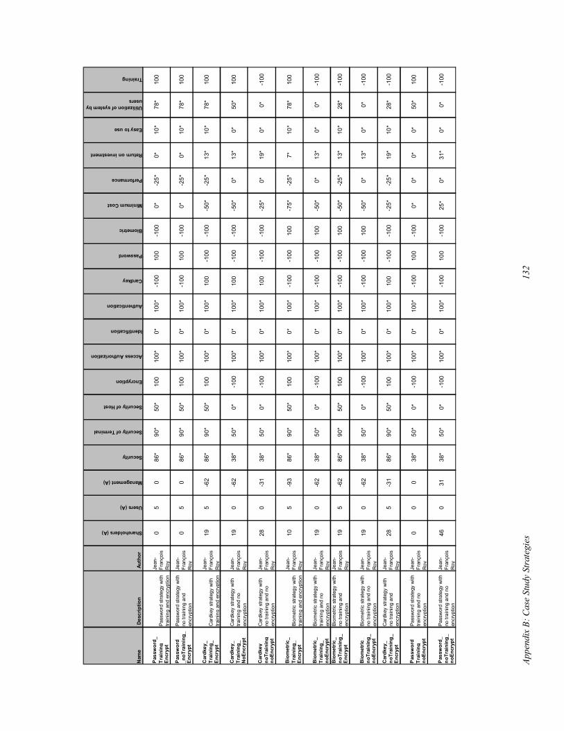
Appe
ndix
B: C
ase
Stud
y St
rate
gies
132
Nam
e D
escr
iptio
n A
utho
r
Shareholders (A)
Users (A)
Management (A)
Security
Security of Terminal
Security of Host
Encryption
Access Authorization
Identification
Authentication
Cardkey
Password
Biometric
Minimum Cost
Performance
Return on investment
Easy to use
Utilization of system by users
Training
Pas
swor
d_Tr
aini
ng_
Enc
rypt
Pas
swor
d_n
oTra
inin
g_E
ncry
pt
Car
dkey
_Tr
aini
ng_
Enc
rypt
Car
dkey
_Tr
aini
ng_
NoE
ncry
pt
Car
dkey
_no
Trai
ning
_no
Encr
ypt
Bio
met
ric_
Trai
ning
_E
ncry
pt
Bio
met
ric_
Trai
ning
_no
Encr
ypt
Bio
met
ric_
noTr
aini
ng_
Enc
rypt
Bio
met
ric_
noTr
aini
ng_
noEn
cryp
t
Car
dke y
_no
Trai
ning
_E
ncry
pt
Pas
swor
d _Tr
aini
ng_
noEn
cryp
t
Pas
swor
d_no
Trai
ning
_no
Encr
ypt
31*
0*0*
-100
100
-100
25*
0*10
0*0*
100*
-100
100
Pass
wor
d st
rate
gy w
ith
no tr
aini
ng a
nd n
o en
cryp
tion
Jean
-Fr
anço
is
Roy
460
3138
*50
*0*
-100
0*0*
0*50
*-1
0010
0-1
000*
-100
100*
0*10
0*0
38*
50*
0*Pa
ssw
ord
stra
tegy
with
tra
inin
g an
d no
en
cryp
tion
Jean
-Fr
anço
is
Roy
00
19*
10*
28*
-100
-100
-100
-25*
-25*
100*
0*10
0*10
0
-100
Car
dkey
stra
tegy
with
no
trai
ning
and
en
cryp
tion
Jean
-Fr
anço
is
Roy
285
-31
86*
90*
50*
100
0*13
*0*
0*-1
00-1
0010
0-5
0*-1
0010
0*0*
100*
-62
38*
50*
0*Bi
omet
ric s
trate
gy w
ith
no tr
aini
ng a
nd n
o en
cryp
tion
Jean
-Fr
anço
is
Ro y
190
13*
10*
28*
-100
-100
100
-50*
-25*
100*
0*10
0*-1
00
-100
Biom
etric
stra
tegy
with
no
trai
ning
and
en
cryp
tion
Jean
-Fr
anço
is
Ro y
195
-62
86*
90*
50*
100
0*13
*0*
0*-1
00-1
0010
0-5
0*-1
0010
0*0*
100*
-62
38*
50*
0*Bi
omet
ric s
trate
gy w
ith
train
ing
and
no
encr
yptio
n
Jean
-Fr
anço
is
Roy
190
7*10
*78
*10
0-1
0010
0-7
5*-2
5*10
0*0*
100*
-100
-100
Biom
etric
stra
tegy
with
tra
inin
g an
d en
cryp
tion
Jean
-Fr
anço
is
Roy
105
-93
86*
90*
50*
100
0*19
*0*
0*10
0-1
00-1
00-2
5*-1
0010
0*0*
100*
-31
38*
50*
0*C
ardk
ey s
trate
gy w
ith
no tr
aini
ng a
nd n
o en
cryp
tion
Jean
-Fr
anço
is
Roy
280
13*
0*50
*10
0-1
00-1
00-5
0*0*
100*
0*10
0*10
0
100
Car
dkey
stra
tegy
with
tra
inin
g an
d no
en
cryp
tion
Jean
-Fr
anço
is
Roy
190
-62
38*
50*
0*-1
00
-25*
13*
10*
78*
100
-100
-100
-50*
100
100*
0*10
0*-6
286
*90
*50
*C
ardk
ey s
trate
gy w
ith
train
ing
and
encr
yptio
n
Jean
-Fr
anço
is
Roy
195
0*10
*78
*10
010
0-1
000*
-25*
100*
0*10
0*-1
00
100
Pass
wor
d st
rate
gy w
ith
no tr
aini
ng a
nd
encr
yptio
n
Jean
-Fr
anço
is
Roy
05
086
*90
*50
*10
0
-25*
0*10
*78
*-1
0010
0-1
000*
100
100*
0*10
0*0
86*
90*
50*
Pass
wor
d st
rate
gy w
ith
train
ing
and
encr
yptio
n
Jean
-Fr
anço
is
Roy
05