request for tender (rft) · 2019-10-01 · page 1 34 lyle street, warracknabeal, vic. 3393 request...
TRANSCRIPT
Page 1
34 Lyle Street, Warracknabeal, Vic. 3393
Request for Tender (RFT)
RFT for: Provision of Design and Construction of Kerb, Channel and Footpath at
Werrigar Street
RFT Reference Number 252/2019
Issue Date 25/09/2019
Tender Closing Time and Lodgement Details
Tender Closing Time: Refer Schedule A, Item 2
Tender Lodgement: Tenders in response to this RFT may be lodged either electronically via the Council’s eTendering website; https://yarriambiack.vic.gov.au/jobs-tenders/tenderlink/ or by hard copy to the Tender Box at 34 Lyle Street, Warracknabeal, Vic. 3393, (PO Box 243, Warracknabeal, Vic. 3393).
If you require assistance completing your electronic submission, please contact: Electronic Tender Box Technical Help Desk - Phone: 1800 233 533 Email: [email protected]
With regards to hard copy Tender submissions, the Tenderer is required to ensure:
its Tender is placed in a sealed envelope marked with the RFT Reference Number and description of Goods and/or Services as shown on the front cover of this RFT but with no indication of the identity of the Tenderer; and
all pages of the Tender are numbered consecutively and the Tender includes an index

RFT for: Design and Construction of Kerb, Channel and Footpath RFT Reference No. 252/2019
Yarriambiack Shire Council Page 2
Nominated Contact Officer(s)
General enquiries:
Contact Name: Joel Turner
Position Title: Manager of Asset Operations
Contact Phone No.: (03) 5398 0125
Contact Email Address: [email protected]
Specification/Technical enquiries:
Contact Name: Pradip Bhujel
Position Title: Asset Engineer
Contact Phone No.: (03) 5398 0108
Contact Email Address: [email protected]
Note: Tenderers must not seek information from any person(s) or rely on any information provided by any person(s) other than the Nominated Contact Officer(s)
Complaints Procedure
If a Tenderer has a complaint about this RFT or the tender process that has not been resolved in the first instance with the Nominated Contact Officer(s) they may escalate the complaint in the following manner:
Any complaint about the RFT or the Tendering Process must be escalated to the General Manager Infrastructure & Planning in writing immediately upon the cause of the complaint arising or becoming known to the Tenderer. The details of the complaints contact person are given in the table below. The written complaint must set out:
a) the basis for the complaint (specifying the issues involved);
b) how the subject of the complaint (and the specific issues) affects the person or organisation making the complaint;
c) any relevant background information; and
d) the outcome desired by the person or organisation making the complaint.
General Manager Infrastructure & Planning shall consider the complaint and provide a written response to the Complainant.
Complaints Contact Name: James Magee
Position Title: General Manager Infrastructure & Planning
Contact Phone No.: (03) 5398 0102
Contact Email Address: [email protected]
RFT for: Design and Construction of Kerb, Channel and Footpath RFT Reference No. 252/2019
Yarriambiack Shire Council Page 3
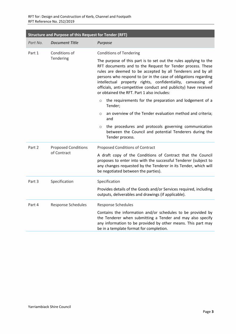
Structure and Purpose of this Request for Tender (RFT)
Part No. Document Title Purpose
Part 1 Conditions of Tendering
Conditions of Tendering
The purpose of this part is to set out the rules applying to the RFT documents and to the Request for Tender process. These rules are deemed to be accepted by all Tenderers and by all persons who respond to (or in the case of obligations regarding intellectual property rights, confidentiality, canvassing of officials, anti-competitive conduct and publicity) have received or obtained the RFT. Part 1 also includes:
o the requirements for the preparation and lodgement of a Tender;
o an overview of the Tender evaluation method and criteria; and
o the procedures and protocols governing communication between the Council and potential Tenderers during the Tender process.
Part 2 Proposed Conditions of Contract
Proposed Conditions of Contract
A draft copy of the Conditions of Contract that the Council proposes to enter into with the successful Tenderer (subject to any changes requested by the Tenderer in its Tender, which will be negotiated between the parties).
Part 3 Specification Specification
Provides details of the Goods and/or Services required, including outputs, deliverables and drawings (if applicable).
Part 4 Response Schedules Response Schedules
Contains the information and/or schedules to be provided by the Tenderer when submitting a Tender and may also specify any information to be provided by other means. This part may be in a template format for completion.

RFT for: Design and Construction of Kerb, Channel and Footpath RFT Reference No. 252/2019
Yarriambiack Shire Council Page 4
Table of Contents
Part 1: Conditions of Tendering 7
1.1 Introduction 7
1.2 Summary of the RFT 7
1.3 Site inspection 7
1.4 Proposed Tender Timetable 7
1.5 eTendering Conditions 7
1.6 Definitions 8
1.7 How to prepare your Tender 8
1.8 Variation to the RFT 9
1.9 Council rights Post-Closing Time 9
1.10 Clarification of the RFT 9
1.11 Liability 10
1.12 Tenderers to inform themselves 10
1.13 Closure of Tender 11
1.14 Acceptance of Tenders 11
1.15 Late Tenders 11
1.16 Alternative Tender or Non-Conforming Tenders 12
1.17 Joint Offers 12
1.18 Statement of Non-Compliance, Departures and Assumptions 12
1.19 Tender Validity Period 12
1.20 Tenderer Mistakes/Errors 12
1.21 Clarification of a Tender 13
1.22 Identity of the Tenderer 13
1.23 Tendered Price 13
1.24 Ownership of Tenders 13
1.25 Confidentiality 13
1.26 Evaluation Methodology 14
1.27 Priority of Documents 14
2. Participation in the Tender Process 15
2.1 Costs of Tender 15
2.2 No obligation to enter into a contract 15
2.3 Canvassing of Officials 15
2.4 Improper assistance 15
2.5 Anti-Competitive Conduct 15
RFT for: Design and Construction of Kerb, Channel and Footpath RFT Reference No. 252/2019
Yarriambiack Shire Council Page 5
2.6 Publicity 16
2.7 Conflict of Interest 16
2.8 Statement of Business Ethics 16
2.9 Governing Law 16
Part 2: Condition of Contract 20
Part 3: Specification 32
3. Introduction and Background 32
3.1 Introduction 32
4. Scope of Works 32
5. Detailed Requirements 32
5.1 Roadworks 32
5.2 Footpath 33
5.3 Kerb and Channel 33
5.4 Nature Strip 33
6. Constructions requirements 34
6.1 Planning phase 34
6.2 Detailed design plans and documentation phase 34
6.3 Construction phase 34
6.4 Commissioning Phase 34
6.5 Quality Standards 35
6.6 Project Timetable 35
6.7 Public Safety 35
6.8 Excavation 35
6.9 Setting Plans and Survey 35
6.10 Services, inspections, openings, etc. public utilities 35
6.11 Contract Documents 36
6.12 Environmental Management Plan 36
6.13 Temporary Services 37
6.14 Site meetings 37
6.15 Inspections 37
6.16 Variations 37
6.17 Tender Submissions 38
7. Insurance Requirements 38
8. Project Timelines 38
Part 4: Response Schedules 39
Instructions to Tenderers 39
RFT for: Design and Construction of Kerb, Channel and Footpath RFT Reference No. 252/2019
Yarriambiack Shire Council Page 6
9. Tender Form 40
9.1 Tenderer’s Details 40
9.2 Tenderer’s Declaration 41
10. Compliance 42
10.1 Statement of non-compliance, departures or assumptions 42
10.2 Alternative Tender or Non-Conforming Tenders 44
10.3 Financial Capacity Information 44
10.4 Current Insurance Certificates 45
10.5 Statement of Conflict 46
10.6 Statement of Threatened or Pending Litigation 46
11. Occupational Health and Safety Management 47
11.1 OH&S Systems, Policies and Management 47
12. Quality Management 49
13. Environmental Management 50
13.1 Environmental Management Systems 50
13.2 Environmental management objectives and measures 50
14. Tender Summary 51
14.1 Overview and History 51
14.2 Summary of Tender 51
15. Relevant experience and past performance 51
15.1 Relevant Experience 51
15.2 Experience and References 51
16. Capability and Capacity 53
16.1 Ability to meet requirements 53
16.2 Business structure/Project Team Structure 53
16.3 Proposed Key Personnel/Account Management 54
16.4 Subcontractors and Consultants 54
16.5 Proposed Subcontractor / Consultant Management Methodology 55
17. Delivery Methodology and Project / Implementation Plan 55
18. Performance Management 55
19. Local Content 56
20. Schedule of Prices 56
21. Table of Attachments 61

RFT for: Design and Construction of Kerb, Channel and Footpath RFT Reference No. 252/2019
Yarriambiack Shire Council Page 7
Part 1: Conditions of Tendering
1.1 Introduction
Yarriambiack Shire Council (Council) is located in the north west of Victoria (Wimmera Southern Mallee Region), about 340 kilometres south-west of the Melbourne CBD. It covers an area of 7,158 square kilometres with a population of approximately 7000. The Yarriambiack Shire offers a relaxed atmosphere, affordable and unique accommodation options, safe and healthy family environments, no peak hour traffic and easy access to public land, lakes and recreational activities. The main towns are Hopetoun, Beulah, Brim, Warracknabeal, Minyip, Rupanyup and Murtoa.
Tenderers are encouraged to visit www.yarriambiack.vic.gov.au to obtain a detailed understanding of the Council.
1.2 Summary of the RFT
The Council is seeking Tenders from appropriately qualified and experienced contractors for the provision of the Goods and/or Services. The Council’s detailed requirements are set out in Part 3 (Specification). This RFT sets out the general requirements for the Goods and/or Services and the terms and conditions of submitting a Tender.
1.3 Site inspection
On request of Tenderer, the Superintendent will arrange time and date for site briefing. All rights are reserved to Council for participating on the process of site briefing.
1.4 Proposed Tender Timetable
Please refer to Schedule A Item 2 of this Part 1 (Conditions of Tendering), for the estimated timetable of key events and dates with regards to this Tender process.
1.5 eTendering Conditions
www.yarriambiack.vic.gov.au/jobs-tenders/tenderlink/ is the electronic tendering system used for the electronic publication of information, including the RFT, online forum for clarification and questions, notifications and addenda, and to accommodate the electronic submission of Tenders.
Tenderers electronically lodging a Tender must review and accept conditions shown on the electronic Tendering website prior to uploading their Tenders.
Electronic lodgement must be fully complete by Closing Time. The electronic link will cease at Closing Time and if your Tender submission is not complete, it will be deemed as a late submission and will not be considered by Council with regards to late submissions.
Similarly, the Council may not consider Tenders that contain corrupt files.
Tenders received via electronic transmission other than through the Council’s electronic Tendering site (including without limitation an e-mail system) will not be accepted.
Any PDF files must be provided in Adobe PDF.
RFT for: Design and Construction of Kerb, Channel and Footpath RFT Reference No. 252/2019
Yarriambiack Shire Council Page 8
1.6 Definitions
Unless the context requires otherwise, the following terms used in this RFT have the meanings ascribed to them as set out below:
Alternative Tender – means a response to this RFT that does not comply with certain requirements of this RFT, but would only require minor adjustments to become a Conforming Tender. It includes a Tender covering only some of the Goods and/or Services.
Closing Time - means the Tender closing date and time for the receipt of Tenders, as set out in Schedule A, Item 2 (as may be updated by the Council and advised to all potential Tenderers in writing).
Conflict - means any actual or potential conflict of interest or duty, or any position that a reasonable person would perceive as giving rise to such a conflict.
Conforming Tender - means a Tender that complies with the requirements of this RFT.
Conditions of Contract - means the contract terms provided in Part 2.
Evaluation Criteria - means the factors which the Council will take into account in any evaluation of Tenders, as included in Schedule A, Item 4 (Evaluation Criteria).
Goods and/or Services - means the deliverable(s) which the preferred Tenderer will be required to provide to the Council, as described at a high level on the front cover of the RFT and in more detail in Part 3 (Specifications), once the Conditions of Contract have been agreed between the preferred Tenderer and the Council.
Nominated Contact Officer - means Council’s nominated Contact Person as set out on Page 2.
Non-Conforming Tender - means a Tender that does not comply with material requirements of this RFT but is not an Alternative Tender.
Period of Contract - means the contract duration
Request for Tender or RFT - means this document inviting Tenderers to submit a Tender to supply the Goods and/or Services on terms based on the Conditions of Contract.
Tender - means a Tenderer’s response documents in the form as specified in Part 4 (Tender Response Schedules) to provide the Council’s requirements as set out in Part 3 (Specification) - and constituting an offer by the Tenderer to the Council in reply to the RFT, to supply the Goods and/or Services on the terms specified in the Conditions of Contract (subject to any amendments to those terms agreed in writing by the parties, based on changes requested by the Tenderer in its Tender).
Tenderer - means a company, person or entity (including representatives) which submits a Tender pursuant to this RFT; and includes, where the context permits, prospective Tenderers and other recipients of this RFT.
Written Representation - means any statement, representation or warranty that has been made by the Council in writing either (a) in this RFT or (b) through the tendering process described in this RFT, and that is directed to Tenderers.
1.7 How to prepare your Tender
o Carefully read all parts of this document and ensure you understand the requirements. Seek clarification where required, as set out in clause 1.10 below.
o Lodge your fully completed Tender (in the form as specified in Part 4 (Tender Response Schedules) and including any other information required by this RFT) before the Closing Time, ensuring you have signed the Statutory Declaration.
RFT for: Design and Construction of Kerb, Channel and Footpath RFT Reference No. 252/2019
Yarriambiack Shire Council Page 9
o Failure to provide the required information in the required format may render a Tender non-conforming and Council may exercise its rights under clause 1.16 (regarding non-conforming tenders).
1.8 Variation to the RFT
In certain circumstances, the Council may need to do any of the following prior to the Closing Time by giving all potential Tenderers reasonable written notice of such:
o Change, vary or amend any information and/or to issue addenda to the RFT. Any such addendum will become part of this RFT;
o Defer the Closing Time or any other date under this RFT;
o Correct any ambiguity or mistake concerning or arising out of this RFT; and/or
o Suspend, terminate or abandon this tendering process.
Where the Council exercises these rights, it may seek amended Tenders.
1.9 Council rights Post-Closing Time
In certain circumstances, the Council may need to do one or any combination of the following after the Closing Time:
o Cease to proceed with the process outlined in this RFT ;
o Accept all or part of a Tender at the price(s) tendered unless the Tender states specifically to the contrary;
o Reject any Tender;
o Accept one or more Tenders;
o Disqualify any Tender that does not include all the information requested or is not in the format required;
o Accept an Alternative Tender or Non-Conforming Tender (provided that it meets all mandatory Evaluation Criteria); and/or
o Obtain further information from the Tenderer for the purposes of clarification or explanation of its Tender. This includes holding interviews with some or all Tenderers, including any personnel nominated by the Tenderer in the Tender.
All Tenders lodged will become the property of Council and on no account will they be returned to Tenderers.
1.10 Clarification of the RFT
If the Tenderer has any doubt as to the meaning of any part of this RFT it should seek clarification before submitting a Tender.
All requests for clarification must be submitted in writing and be directed to the Nominated Contact Officer(s) at least three days prior to the Closing Time. The Council reserves the right not to answer requests after this period.
The Council is not obliged to respond to any question or request.
If the question or request is relevant to other prospective Tenderers, the Council will make available to such other prospective Tenderers details of such a question or request together with any response, in which event those details shall form part of this RFT.
RFT for: Design and Construction of Kerb, Channel and Footpath RFT Reference No. 252/2019
Yarriambiack Shire Council Page 10
1.11 Liability
The Tenderer acknowledges that the Council (including the Council’s officers, employees, agents or advisers) will not be bound by any statement, representation or warranty made by, or on behalf of, the Council in relation to the RFT, the tendering process or the subject matter of this RFT, unless that statement, representation or warranty is a Written Representation. Subject to the last two paragraphs in this clause 1.11, if any Written Representation subsequently proves incorrect or incomplete, then the issue will be addressed through change control in the context of any ensuing contract between the Council and the Tenderer (each acting reasonably). While all due care has been taken in the preparation of this RFT, and while the Tenderer may rely on any Written Representations for the purposes of submitting its Tender, the Tenderer acknowledges that it must not otherwise rely on, and has no separate ability to claim against the Council (or the Council’s officers, employees, agents or advisers) in respect of, the adequacy, accuracy, reasonableness or completeness of the information communicated or provided in this RFT or through the tendering process.
To the fullest extent allowed by applicable law, all statutory or implied warranties are excluded and of no effect and neither the Council, nor the Council’s officers, employees, agents or advisers will be liable for any loss, costs, expenses or damage:
o arising as a result of reliance on such information by Tenderer or any other person; or o otherwise incurred by Tenderers or any other persons at any time, in relation to the tendering
process, evaluation of Tender, any contract negotiation or the selection process generally. If a Tenderer finds any discrepancy, ambiguity, error or inconsistency in the RFT or any other information provided by the Council (other than minor clerical matters), the Tenderer must promptly notify the Council’s Nominated Contact Officer in writing, so that there is fair opportunity to consider what corrective action is necessary (if any).
Any actual discrepancy, ambiguity, error or inconsistency in the RFT or any other information provided by the Council will be corrected by the Council and provided (or the proper information made available) to all Tenderers without attribution to the Tenderer that provided the notice.
1.12 Tenderers to inform themselves
The information in this RFT has been provided in good faith. It is intended only as an explanation of the Council's requirements and is not intended to form the basis of a Tenderer's decision on whether to enter into any contractual relationship with the Council.
By responding to this RFT, the Tenderer will be deemed to have acknowledged and agreed that it has done so on the basis that it has the necessary skills, knowledge and experience to provide the Goods and/or Services. Tenderers will be deemed to have:
o fully examined and understood the requirements of this RFT (including all documents and attachments referenced) and any other information made available by the Council to Tenderers in relation to this RFT;
o satisfied itself that it has a full set of the RFT documents and all relevant attachments;
o made its own enquiries and assessed all risks regarding this RFT and the tendering process;
o not relied upon any warranty or representation (whether oral or in writing or by conduct) made on behalf of the Council except where such warranty or representation is set out in this RFT or made in writing by Council through the processes specified by these Conditions of Tender;
RFT for: Design and Construction of Kerb, Channel and Footpath RFT Reference No. 252/2019
Yarriambiack Shire Council Page 11
o ensured that its Tender addresses all the requested information in Part 4 and is presented in the required format, is accurate and complete, and is not misleading in any way;
o acknowledged that the Council will rely on information provided by the Tenderer at all stages of this tendering process. Any information provided by the preferred Tenderer may (along with this RFT and the Tender itself) form part of the final agreed form of the Conditions of Contract;
o ensured that it complies with all applicable laws with regard to preparing its Tender (including but not limited to Australian Competition and Consumer Law and Occupational Health and Safety Requirements);
o met all costs and expenses related to the preparation and lodgement of its Tender, and will meet all of its costs and expenses arising from subsequent negotiation, and any future costs connected with or relating to the tendering process; and
o satisfied itself as to the correctness and sufficiency of its Tender including tendered prices.
1.13 Closure of Tender
The Tender must be lodged by the Closing Time and by the method as outlined in Schedule A (as may be deferred by Council in its discretion).
Please refer to Part 4 for the list of documents to be completed and submitted by the Tenderer before the Closing Time and also refer to the earlier clause regarding eTendering for requirements applying to electronic submission.
1.14 Acceptance of Tenders
Unless otherwise stated in this RFT, Tenders may be submitted for all or part of the Council’s requirements and may be accepted by the Council either wholly or in part. The Council is not bound to accept the lowest price or any Tender (and may reject any or all Tenders).
The Council reserves the right to not accept a Tender (or any part of it) and is under no obligation to give reasons for not accepting a Tender. Tenderers will be informed in writing of the outcome of their Tender at the conclusion of the RFT process. The Council may, in its absolute discretion, invite unsuccessful Tenderers to a de-brief meeting on the outcome of the RFT.
If any Tender is accepted by the Council, such acceptance shall be conditional until both parties signing a contract for the Goods and/or Services, based on the Conditions of Contract (subject to negotiation of any amendments to those conditions requested by Tenderer in its Tender).
Whether or not required by Part 4, it would be helpful if the Tenderer were to provide with its Tender, a new version of the Conditions of Contract marked up with any changes the Tenderer would require.
1.15 Late Tenders
Tenders lodged or received by Council after the Tender Closing Time are deemed to be late and will be disqualified and ineligible for consideration unless the Tenderer can clearly document to the satisfaction of Council that an event of exceptional circumstances caused the Tender to be lodged after the Closing Time.
Consideration of a Tender under this circumstance will be at the sole discretion of the Council.
The determination of the Council as to the actual time that the Tender was lodged is final. All offers lodged after the Closing Time will be recorded by the Council.
Unless the Council is satisfied there are exceptional circumstances, the Council will inform a Tenderer whose offer was lodged after the Closing Time of their ineligibility for consideration.

RFT for: Design and Construction of Kerb, Channel and Footpath RFT Reference No. 252/2019
Yarriambiack Shire Council Page 12
In the event of a hard copy submission, a late Tender will only be considered if the Tenderer satisfies the Council that the Tender and all other essential information was posted or lodged at a Post Office or other recognised delivery agency in sufficient time to enable the documents to have been received by the Council in the ordinary course of business before the Closing Time, or the Council receives those documents within such period as it decides to be reasonable in the circumstances.
1.16 Alternative Tender or Non-Conforming Tenders
The Council reserves the right, in its absolute discretion, to consider an Alternative Tender or Non-Conforming Tender (provided that any mandatory Evaluation Criteria are met), but is not obliged to do so. If a Tenderer wishes to submit an Alternative Tender or Non-Conforming Tender it must also:
i. Submit a Conforming Tender; and
ii. Submit a copy of the clearly identified Alternative Tender or Non-Conforming Tender in a marked up form, which identifies all departures from the Conforming Tender. In order to be considered for evaluation, any such Alternative Tender or Non-Conforming Tender must:
1. Fully describe its advantages, disadvantages, limitations and capabilities;
2. Be fully costed;
3. Permit ready comparison of the alternative offer with complying Tenders; and
4. Expressly state where it does not comply with the terms of this RFT.
1.17 Joint Offers
Council will accept a joint offer from two or more Tenderers.
1.18 Statement of Non-Compliance, Departures and Assumptions
The Tenderer must declare and detail any non-compliance with, departures from or assumptions in relation to, the RFT in its Tender, at item 10.1 Part 4, Response Schedules.
These non-compliances, departures or assumptions must address any material conditions or positions in relation to the Conditions of Contract and/or Part 3 (Specification).
Submitted Tenders will be deemed as accepting and complying with all of the Conditions of Contract and the Specification unless explicitly noted at item 10.1, Part 4, Tender Response Schedules.
1.19 Tender Validity Period
All Tenders will remain valid and open for acceptance for three (3) months from the Closing Time unless extended by mutual agreement between the Council and the Tenderer(s) in writing.
1.20 Tenderer Mistakes/Errors
The Council may, at its discretion, permit a Tenderer to correct an unintentional mistake or anomaly in its Tender after the Closing Time.
In no event will any correction be permitted if the Council reasonably considers that the correction would materially alter the Tender.
Such a variation may be made either:
i. at the request of the Council, or

RFT for: Design and Construction of Kerb, Channel and Footpath RFT Reference No. 252/2019
Yarriambiack Shire Council Page 13
ii. with the consent of the Council at the request of the Tenderer, but only if, in the circumstances, it appears reasonable to the Council to allow the Tenderer to provide correction.
If a Tender is varied in accordance with this clause 1.20, and if in the interests of fairness it is deemed necessary, the Council will notify in writing each other Tenderer whose Tender circumstances have the same or similar characteristics as the varied Tender, and provide that Tenderer with the opportunity of varying its Tender in a similar way.
1.21 Clarification of a Tender
If in the opinion of the Council, a Tender is unclear in any respect, the Council may seek clarification from a Tenderer. Failure to supply clarification to the satisfaction of the Council may render the Tender liable to disqualification.
The Council is under no obligation to seek clarification and reserves the right to disregard any clarification that it considers to be unsolicited or otherwise impermissible.
1.22 Identity of the Tenderer
The identity of the Tenderer is fundamental to the Council. The Tenderer (and the party to any ensuing contract with the Council) will be the company, person or entity (or in each case, multiple for joint Tenders) named as the Tenderer in the Offer Form in Part 4 (Tender Response Schedules).
The Council may reject any Tender that is not from or does not disclose a solvent legal entity capable of entering into a contract with the Council. The Tenderer must provide its Australian Business Number (ABN), or, if it does not have an ABN, the reason for not having one.
1.23 Tendered Price
The price outlined in the Tender must quote all prices exclusive of GST.
The price tendered must be the total price, including all fees and costs. The pricing will be used by the Council for budgetary purposes and therefore constitutes a tendered price and quotation and not an estimate.
1.24 Ownership of Tenders
Upon submission, all Tenders, documents and other information submitted by the Tenderer as part of or in support of a Tender will become property of the Council.
The Tenderer will retain copyright and other intellectual property rights contained in its Tender, however each Tenderer, by submission of its offer, is deemed to have granted an irrevocable royalty-free licence to the Council to reproduce, in whole or part, its Tender for the purposes of enabling the Council, or such persons or bodies as the Council reasonably considers necessary, to evaluate, clarify or vary the Tender or to negotiate any resulting contract.
Tenderers and other recipients of this RFT do not acquire intellectual property rights in the RFT documents and must not reproduce any of the RFT documents in any material form without the written permission of the Council other than for use strictly for the purpose of preparing a Tender.
1.25 Confidentiality
Each Tenderer or other recipient of this RFT must keep confidential the RFT and any information provided by the Council in connection with the RFT including any information marked as confidential or which the Tenderer / recipient knows or ought reasonably to know is confidential or should be treated as such.
RFT for: Design and Construction of Kerb, Channel and Footpath RFT Reference No. 252/2019
Yarriambiack Shire Council Page 14
All Tenders received by Council will be held in confidence. The Tenderer acknowledges that the Council may disclose any information in the Tender to its professional advisors or if required by law (including, but not limited to, as required under the Freedom of Information Act 1982 (Vic)), or government policy.
1.26 Evaluation Methodology
Tenders will be evaluated against the Evaluation Criteria set out in Schedule A, Item 4 of this RFT.
Information provided by the Tenderer in the Response Schedules (Part 4) of this RFT, will be the basis of the evaluation against these criteria. Tenderers are advised to respond clearly to all of the requirements listed in the Specification (Part 3) of this RFT.
In evaluating offers, the Council will have regard to:
(a) specific evaluation criteria identified in the list set out in Schedule A, Item 4 including mandatory requirements, if applicable;
(a) the overall value for money proposition presented in the offer; and
(b) the particular weighting assigned (in Schedule A, Item 4) to any or all of the criteria (noting that any criteria for which a weighting has not been assigned should be assumed to have equal weighting.)
Any Evaluation Criteria identified as Mandatory Criteria MUST be met by the Tenderer. For these criteria, a Tender will be assessed on a Yes/No (Pass/Fail) basis. If a Tender fails to fully comply with those evaluation criteria, it will be excluded without further consideration.
Tender will be assessed against other (non-mandatory) Evaluation Criteria, using a weighted scoring process based on information provided with the Tender.
Council may, in its sole discretion, seek clarification from any Tenderer regarding information contained in the Tender and may do so without notification to any other Tenderer.
A Tenderer may be invited to a one-on-one evaluation interview in order to review and clarify the Tender and to enable Council to interview key personnel identified in the Tender.
1.27 Priority of Documents
If there is any inconsistency between Part 1 (Conditions of Tendering) of this RFT and any other parts of the RFT, then unless it is expressly stated that the other part was intended to override this Part 1 (and except where the inconsistency is identified prior to the Closing Time (in which case, clause 1.9 will apply), the terms of this Part 1 (Conditions of Tendering) will prevail to the extent of that inconsistency.

RFT for: Design and Construction of Kerb, Channel and Footpath RFT Reference No. 252/2019
Yarriambiack Shire Council Page 15
2. Participation in the Tender Process 2.1 Costs of Tender
Tenderers remain responsible for all costs incurred by them in connection with their Tenders whether before or after the Closing Time and whether incurred directly by them or their advisers including costs arising as a direct or indirect consequence of amendments made to the RFT by the Council. For the avoidance of doubt, the Council shall have no liability whatsoever to Tenderers for the costs of any negotiations conducted in the event that the Council decides not to accept any Tenders.
2.2 No obligation to enter into a contract
By issuing this RFT, Council is under no obligation (whether equitable or legal) to proceed either in whole or in part with the procurement to which the RFT relates. Council is not committed contractually or in any way to any person who may receive the RFT or submit a Tender.
2.3 Canvassing of Officials
Any Tenderer or other recipient of this RFT who solicits or attempts to solicit support for its Tender or otherwise seeks to influence the outcome of the Tender process by:
a) offering any inducement, fee, or reward, to any member or officer of the Council, including Councillors, or to any person engaged by the Council, or acting as an adviser for the Council; or
b) canvassing any persons referred to in this document; or
c) contacting any member or officer of the Council, including Councillors or any person engaged by Council, about the RFT or any process relating thereto, except as authorised by this RFT;
d) causing or inducing any person to enter such agreement or to inform the Tenderer of the amount or approximate amount of any rival Tenderer; or
e) canvassing any of the persons as set out above in connection with the RFT or the outcome of the Tender process,
will be disqualified from involvement in the RFT process.
2.4 Improper assistance
Tenderers must not seek or obtain the assistance of employees, agents or contractors of the Council in the preparation of their Tender. In addition to any other remedies available to it under law or contract, the Council may, in its absolute discretion, immediately disqualify a Tenderer that it believes has sought or obtained such assistance.
2.5 Anti-Competitive Conduct
Tenderers (and other recipients of this RFT) must not engage in any collusion, anti-competitive conduct or any other similar conduct with any other Tenderer or any other person in relation to the preparation, content or lodgement of their Tender. This includes, but is not limited to, the Tenderer:
a) fixing or adjusting the amount of its Tender by or in accordance with any agreement or arrangement with any other Tenderer; or
b) entering into any agreement or arrangement with any other Tenderer that it shall refrain from tendering or as to the amount of any Tender to be submitted; or
RFT for: Design and Construction of Kerb, Channel and Footpath RFT Reference No. 252/2019
Yarriambiack Shire Council Page 16
c) paying (or offering or agreeing to pay) any sum of money, inducement or valuable consideration, directly or indirectly to any person for doing, having done, causing, or having caused to be done, any act or omission in relation to any other Tender or proposed Tender; or
d) communicating to any person other than the Council the amount or approximate amount of its proposed Tender (except where such disclosure made in confidence in order to obtain quotations necessary for the preparation of the Tender, for insurance or contract guarantee bonds and/or performance bonds or professional advice required for the preparation of a Tender).
Where such actions are drawn to the Council’s attention, relevant Tenderers will be disqualified from any further involvement in this tender process.
2.6 Publicity
Recipients of this RFT must not undertake any publicity activities with any part of the media in relation to the RFT, tendering process or Tender without the prior written agreement of the Council, including agreement on the format and content of any publicity.
2.7 Conflict of Interest
The Tenderer represents that it has not placed itself in a position that may give rise to any Conflict in connection with the RFT and Tender. Alternatively, the Tenderer must:
(a) disclose any Conflict in its Tender;
(b) notify the Council if any Conflict arises after lodgement of its Tender; and
(c) indicate the strategy it has in place to manage the Conflict.
The Council may disqualify a Tenderer from the tendering process if the Tenderer fails to notify the Council of any Conflict or if the Council is not satisfied with the strategy the Tenderer has in place to manage the Conflict.
2.8 Statement of Business Ethics
Council is committed to the highest standards of honesty, fairness and integrity in all its business dealings. Council’s Statement of Business Ethics sets out the standards of behaviour that Council expects from its supply partners. These standards of behaviour relate to fair, ethical and honest dealings with Council, and ensuring that the best level of service is provided to the community. This document is also attached to this RFT. Breaches of this Statement may constitute grounds for disqualification of Tender.
2.9 Governing Law
These conditions of tendering are governed by the laws of the State of Victoria and the parties submit to the exclusive jurisdiction of the courts of that State.
RFT for: Design and Construction of Kerb, Channel and Footpath RFT Reference No. 252/2019
Yarriambiack Shire Council Page 17
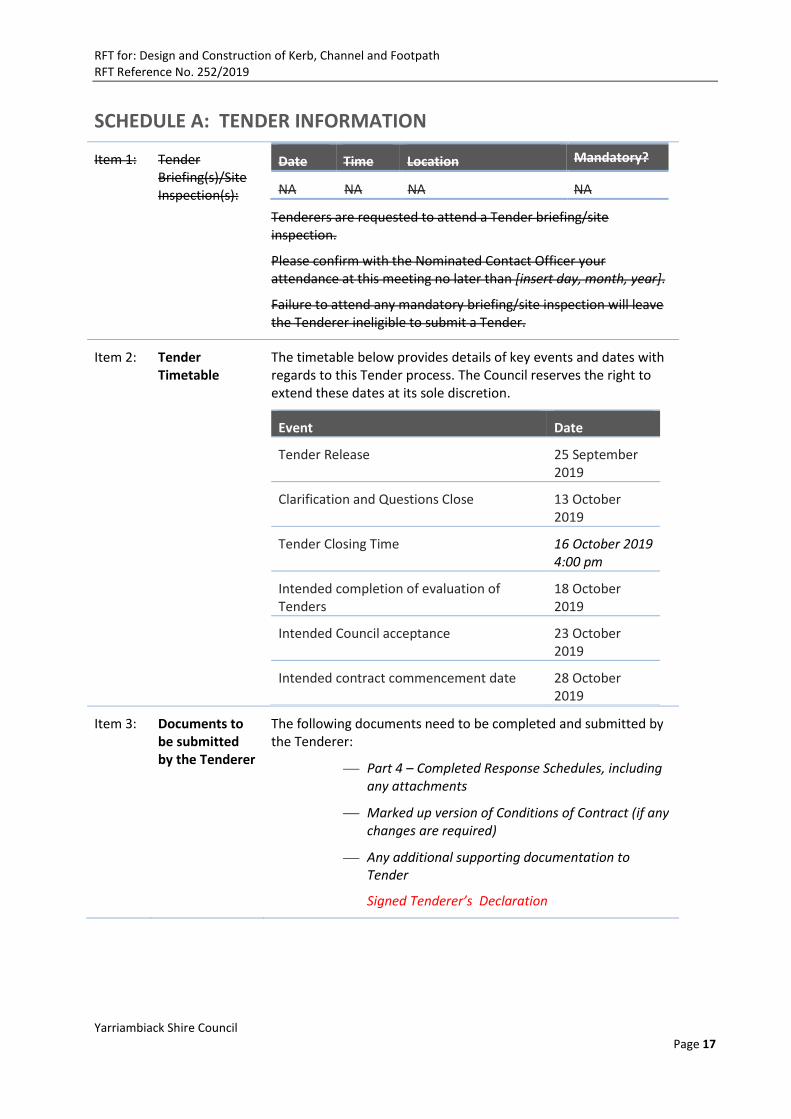
SCHEDULE A: TENDER INFORMATION
Item 1: Tender Briefing(s)/Site Inspection(s):
Date Time Location Mandatory?
NA NA NA NA
Tenderers are requested to attend a Tender briefing/site inspection.
Please confirm with the Nominated Contact Officer your attendance at this meeting no later than [insert day, month, year].
Failure to attend any mandatory briefing/site inspection will leave the Tenderer ineligible to submit a Tender.
Item 2: Tender Timetable
The timetable below provides details of key events and dates with regards to this Tender process. The Council reserves the right to extend these dates at its sole discretion.
Event Date
Tender Release 25 September 2019
Clarification and Questions Close 13 October 2019
Tender Closing Time 16 October 2019 4:00 pm
Intended completion of evaluation of Tenders
18 October 2019
Intended Council acceptance 23 October 2019
Intended contract commencement date 28 October 2019
Item 3: Documents to be submitted by the Tenderer
The following documents need to be completed and submitted by the Tenderer:
Part 4 – Completed Response Schedules, including any attachments
Marked up version of Conditions of Contract (if any changes are required)
Any additional supporting documentation to Tender
Signed Tenderer’s Declaration
RFT for: Design and Construction of Kerb, Channel and Footpath RFT Reference No. 252/2019
Yarriambiack Shire Council Page 18
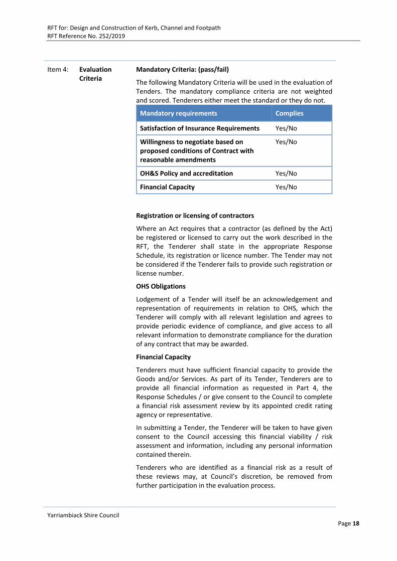
Item 4: Evaluation Criteria
Mandatory Criteria: (pass/fail)
The following Mandatory Criteria will be used in the evaluation of Tenders. The mandatory compliance criteria are not weighted and scored. Tenderers either meet the standard or they do not.
Mandatory requirements Complies
Satisfaction of Insurance Requirements Yes/No
Willingness to negotiate based on proposed conditions of Contract with reasonable amendments
Yes/No
OH&S Policy and accreditation Yes/No
Financial Capacity Yes/No
Registration or licensing of contractors
Where an Act requires that a contractor (as defined by the Act) be registered or licensed to carry out the work described in the RFT, the Tenderer shall state in the appropriate Response Schedule, its registration or licence number. The Tender may not be considered if the Tenderer fails to provide such registration or license number.
OHS Obligations
Lodgement of a Tender will itself be an acknowledgement and representation of requirements in relation to OHS, which the Tenderer will comply with all relevant legislation and agrees to provide periodic evidence of compliance, and give access to all relevant information to demonstrate compliance for the duration of any contract that may be awarded.
Financial Capacity
Tenderers must have sufficient financial capacity to provide the Goods and/or Services. As part of its Tender, Tenderers are to provide all financial information as requested in Part 4, the Response Schedules / or give consent to the Council to complete a financial risk assessment review by its appointed credit rating agency or representative.
In submitting a Tender, the Tenderer will be taken to have given consent to the Council accessing this financial viability / risk assessment and information, including any personal information contained therein.
Tenderers who are identified as a financial risk as a result of these reviews may, at Council’s discretion, be removed from further participation in the evaluation process.
RFT for: Design and Construction of Kerb, Channel and Footpath RFT Reference No. 252/2019
Yarriambiack Shire Council Page 19
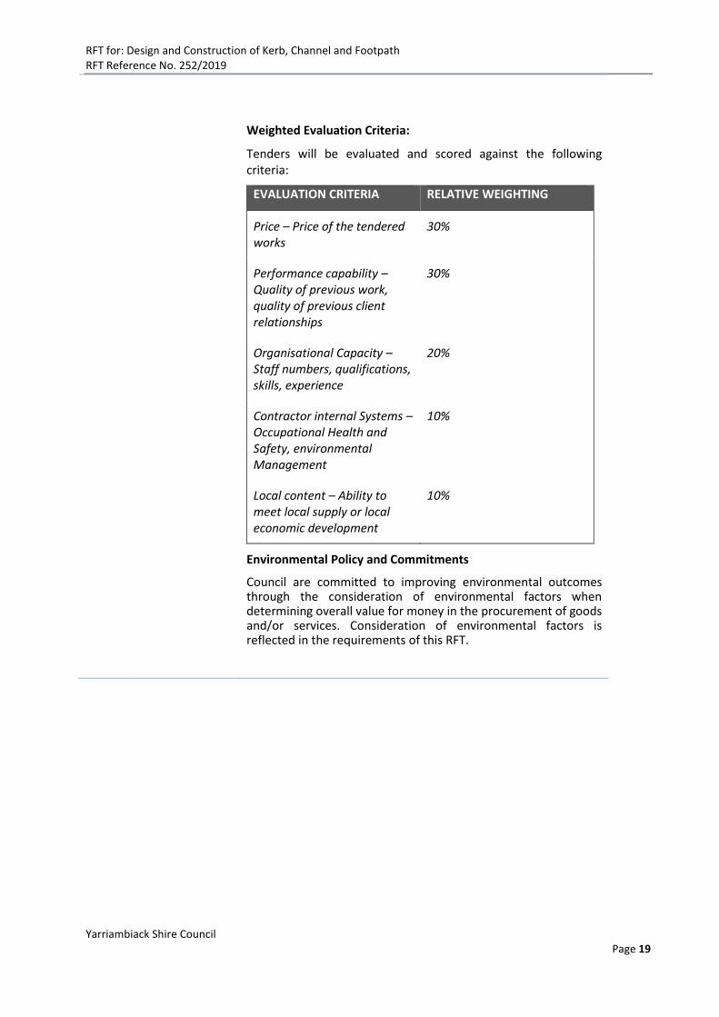
Weighted Evaluation Criteria:
Tenders will be evaluated and scored against the following criteria:
EVALUATION CRITERIA RELATIVE WEIGHTING
Price – Price of the tendered works
30%
Performance capability – Quality of previous work, quality of previous client relationships
30%
Organisational Capacity – Staff numbers, qualifications, skills, experience
20%
Contractor internal Systems – Occupational Health and Safety, environmental Management
10%
Local content – Ability to meet local supply or local economic development
10%
Environmental Policy and Commitments
Council are committed to improving environmental outcomes through the consideration of environmental factors when determining overall value for money in the procurement of goods and/or services. Consideration of environmental factors is reflected in the requirements of this RFT.
RFT for: Design and Construction of Kerb, Channel and Footpath RFT Reference No. 252/2019
Yarriambiack Shire Council Page 20
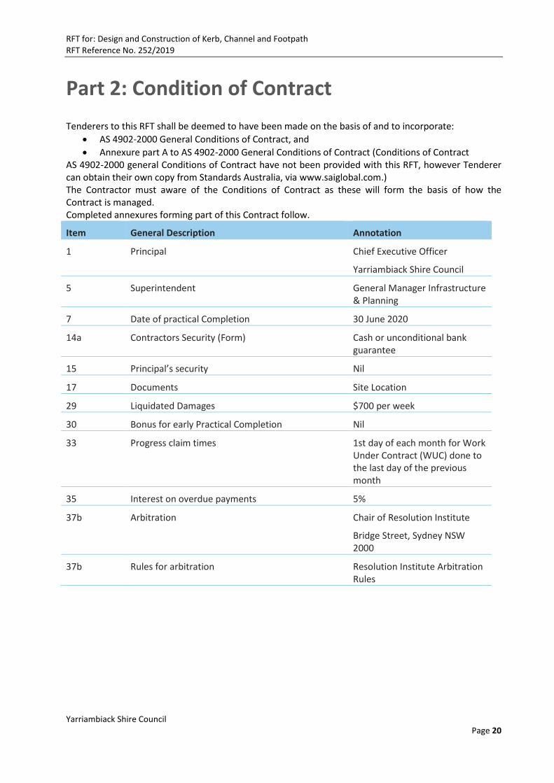
Part 2: Condition of Contract
Tenderers to this RFT shall be deemed to have been made on the basis of and to incorporate:
AS 4902-2000 General Conditions of Contract, and
Annexure part A to AS 4902-2000 General Conditions of Contract (Conditions of Contract AS 4902-2000 general Conditions of Contract have not been provided with this RFT, however Tenderer can obtain their own copy from Standards Australia, via www.saiglobal.com.) The Contractor must aware of the Conditions of Contract as these will form the basis of how the Contract is managed. Completed annexures forming part of this Contract follow.
Item General Description Annotation
1 Principal Chief Executive Officer
Yarriambiack Shire Council
5 Superintendent General Manager Infrastructure & Planning
7 Date of practical Completion 30 June 2020
14a Contractors Security (Form) Cash or unconditional bank guarantee
15 Principal’s security Nil
17 Documents Site Location
29 Liquidated Damages $700 per week
30 Bonus for early Practical Completion Nil
33 Progress claim times 1st day of each month for Work Under Contract (WUC) done to the last day of the previous month
35 Interest on overdue payments 5%
37b Arbitration Chair of Resolution Institute
Bridge Street, Sydney NSW 2000
37b Rules for arbitration Resolution Institute Arbitration Rules
RFT for: Design and Construction of Kerb, Channel and Footpath RFT Reference No. 252/2019
Yarriambiack Shire Council Page 21
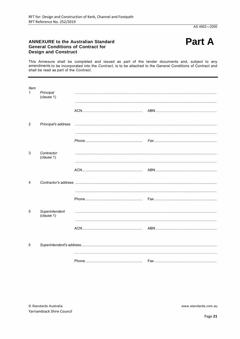
AS 4902-2000 ANNEXURE to the Australian Standard General Conditions of Contract for Design and Construct This Annexure shall be completed and issued as part of the tender documents and, subject to any amendments to be incorporated into the Contract, is to be attached to the General Conditions of Contract and shall be read as part of the Contract. Item 1 Principal ........................................................................................................................................... (clause 1) ........................................................................................................................................... ACN ........................................................... ABN ............................................................ 2 Principal's address ........................................................................................................................................... ........................................................................................................................................... Phone ........................................................ Fax ............................................................. 3 Contractor ........................................................................................................................................... (clause 1) ........................................................................................................................................... ACN ........................................................... ABN ............................................................ 4 Contractor's address ........................................................................................................................................... ........................................................................................................................................... Phone ........................................................ Fax ............................................................. 5 Superintendent ........................................................................................................................................... (clause 1) ........................................................................................................................................... ACN ........................................................... ABN ............................................................ 6 Superintendent's address .....................................................................................................................................
........................................................................................................................... Phone ........................................................ Fax ............................................................. © Standards Australia www.standards.com.au
Part A
RFT for: Design and Construction of Kerb, Channel and Footpath RFT Reference No. 252/2019
Yarriambiack Shire Council Page 22
AS 4902-2000
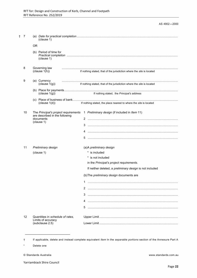
† 7 (a) Date for practical completion .........................................................................................................................
(clause 1) OR (b) Period of time for Practical completion ..................................................................................................................................... (clause 1) 8 Governing law ........................................................................................................................................... (clause 1(h)) If nothing stated, that of the jurisdiction where the site is located 9 (a) Currency ........................................................................................................................................... (clause 1(g)) If nothing stated, that of the jurisdiction where the site is located (b) Place for payments ........................................................................................................................................ (clause 1(g)) If nothing stated, the Principal’s address (c) Place of business of bank .............................................................................................................................. (clause 1(d)) If nothing stated, the place nearest to where the site is located 10 The Principal’s project requirements 1 Preliminary design (if included in Item 11) are described in the following documents 2 ............................................................................................................ (clause 1) 3 ............................................................................................................ 4 ............................................................................................................ 5 ............................................................................................................ 11 Preliminary design (a) A preliminary design
(clause 1) * is included
* is not included
in the Principal’s project requirements.
If neither deleted, a preliminary design is not included (b) The preliminary design documents are
1 ............................................................................................................ 2 ............................................................................................................ 3 ............................................................................................................ 4 ............................................................................................................ 5 ............................................................................................................ 12 Quantities in schedule of rates, Upper Limit .............................................................................................. Limits of accuracy (subclause 2.5) Lower Limit .............................................................................................. ___________________________ † If applicable, delete and instead complete equivalent Item ln the separable portions section of the Annexure Part A * Delete one © Standards Australia www.standards.com.au
RFT for: Design and Construction of Kerb, Channel and Footpath RFT Reference No. 252/2019
Yarriambiack Shire Council
Page 23
AS 4902-2000
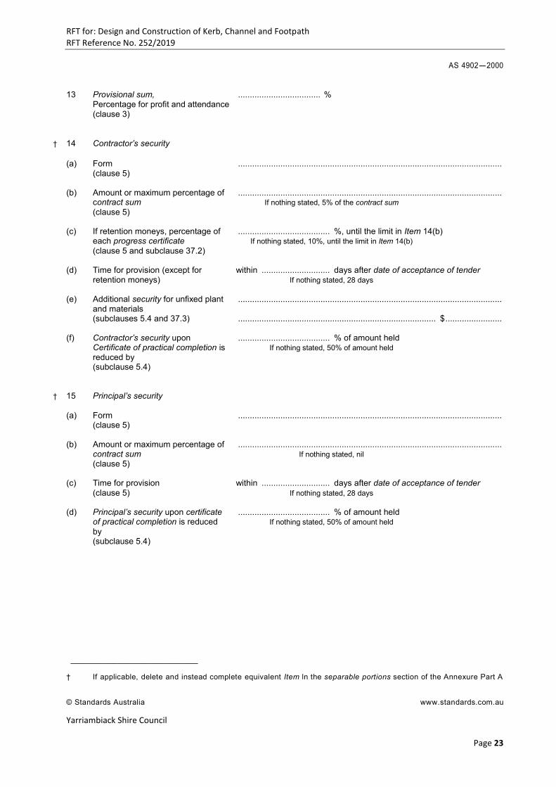
13 Provisional sum, ................................... % Percentage for profit and attendance (clause 3)
† 14 Contractor’s security (a) Form ................................................................................................................ (clause 5) (b) Amount or maximum percentage of ................................................................................................................ contract sum If nothing stated, 5% of the contract sum (clause 5) (c) If retention moneys, percentage of ....................................... %, until the limit in Item 14(b) each progress certificate If nothing stated, 10%, until the limit in Item 14(b) (clause 5 and subclause 37.2) (d) Time for provision (except for within ............................. days after date of acceptance of tender retention moneys) If nothing stated, 28 days (e) Additional security for unfixed plant ................................................................................................................ and materials (subclauses 5.4 and 37.3) .................................................................................... $ ........................ (f) Contractor’s security upon ....................................... % of amount held Certificate of practical completion is If nothing stated, 50% of amount held reduced by (subclause 5.4)
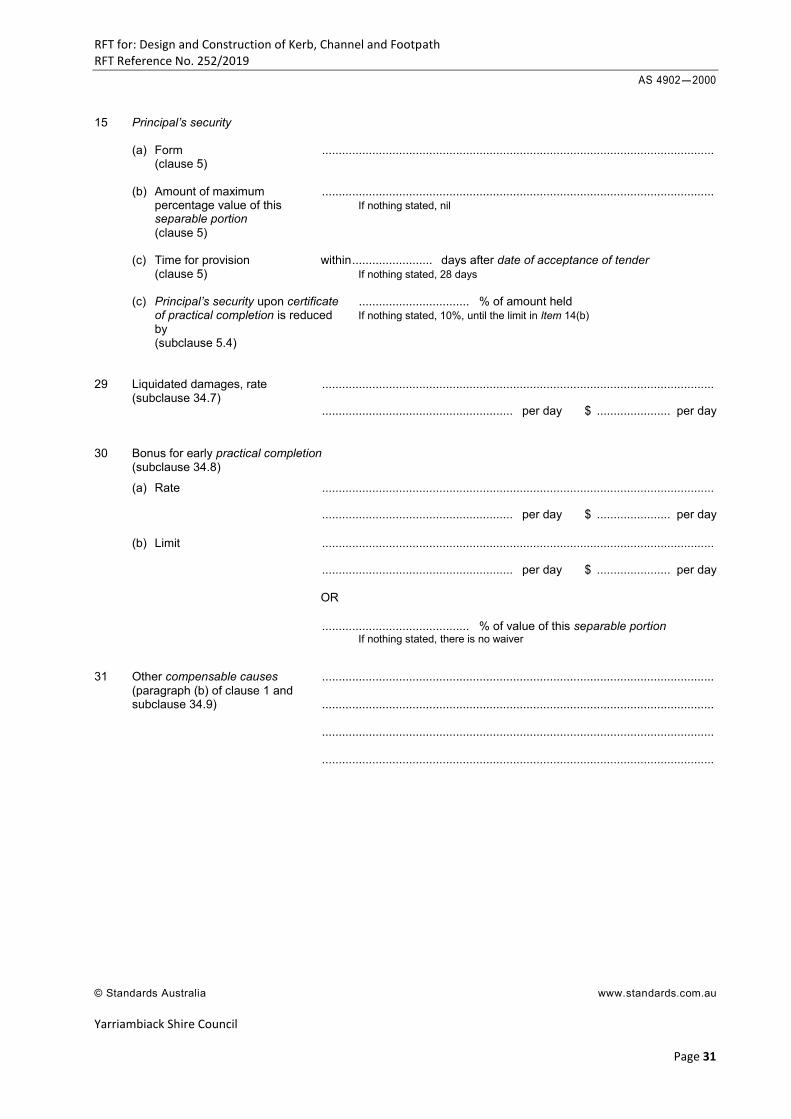
† 15 Principal’s security
(a) Form ................................................................................................................ (clause 5) (b) Amount or maximum percentage of ................................................................................................................ contract sum If nothing stated, nil (clause 5) (c) Time for provision within ............................. days after date of acceptance of tender (clause 5) If nothing stated, 28 days (d) Principal’s security upon certificate ....................................... % of amount held of practical completion is reduced If nothing stated, 50% of amount held by (subclause 5.4) ___________________________ † If applicable, delete and instead complete equivalent Item ln the separable portions section of the Annexure Part A © Standards Australia www.standards.com.au
RFT for: Design and Construction of Kerb, Channel and Footpath RFT Reference No. 252/2019
Yarriambiack Shire Council
Page 24
AS 4902-2000
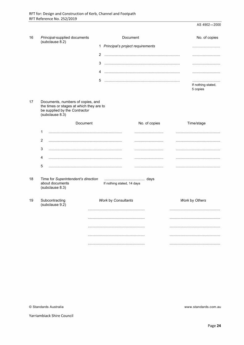
16 Principal-supplied documents Document No. of copies (subclause 8.2) 1 Principal’s project requirements ........................... 2 ......................................................................... ........................... 3 ......................................................................... ........................... 4 ......................................................................... ........................... 5 ......................................................................... ........................... If nothing stated, 5 copies 17 Documents, numbers of copies, and the times or stages at which they are to be supplied by the Contractor (subclause 8.3) Document No. of copies Time/stage 1 ....................................................................... ............................ ........................................... 2 ....................................................................... ............................ ........................................... 3 ....................................................................... ............................ ........................................... 4 ....................................................................... ............................ ........................................... 5 ....................................................................... ............................ ........................................... 18 Time for Superintendent’s direction ....................................... days about documents If nothing stated, 14 days (subclause 8.3) 19 Subcontracting Work by Consultants Work by Others (subclause 9.2) ....................................................... ................................................. ....................................................... ................................................. ....................................................... ................................................. ....................................................... ................................................. ....................................................... ................................................. © Standards Australia www.standards.com.au
RFT for: Design and Construction of Kerb, Channel and Footpath RFT Reference No. 252/2019
Yarriambiack Shire Council
Page 25
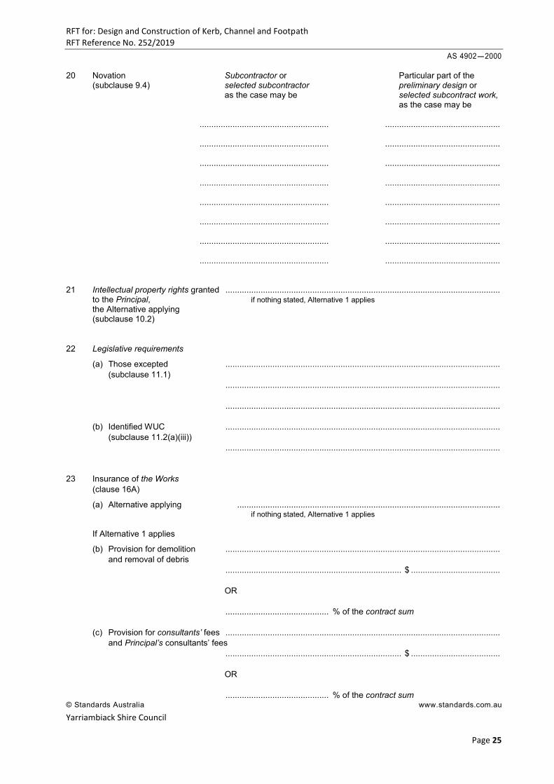
AS 4902-2000 20 Novation Subcontractor or Particular part of the (subclause 9.4) selected subcontractor preliminary design or as the case may be selected subcontract work, as the case may be ....................................................... ................................................. ....................................................... ................................................. ....................................................... ................................................. ....................................................... ................................................. ....................................................... ................................................. ....................................................... ................................................. ....................................................... ................................................. ....................................................... ................................................. 21 Intellectual property rights granted ..................................................................................................................... to the Principal, if nothing stated, Alternative 1 applies the Alternative applying (subclause 10.2) 22 Legislative requirements
(a) Those excepted ..................................................................................................................... (subclause 11.1) ..................................................................................................................... ..................................................................................................................... (b) Identified WUC ..................................................................................................................... (subclause 11.2(a)(iii)) ..................................................................................................................... 23 Insurance of the Works (clause 16A)
(a) Alternative applying ................................................................................................................ if nothing stated, Alternative 1 applies If Alternative 1 applies
(b) Provision for demolition ..................................................................................................................... and removal of debris ........................................................................... $ ...................................... OR ............................................ % of the contract sum (c) Provision for consultants’ fees ..................................................................................................................... and Principal’s consultants’ fees ........................................................................... $ ...................................... OR ............................................ % of the contract sum © Standards Australia www.standards.com.au
RFT for: Design and Construction of Kerb, Channel and Footpath RFT Reference No. 252/2019
Yarriambiack Shire Council
Page 26
AS 4902-2000
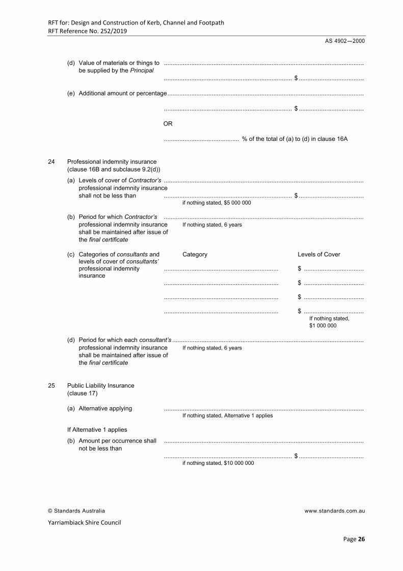
(d) Value of materials or things to ..................................................................................................................... be supplied by the Principal ........................................................................... $ ...................................... (e) Additional amount or percentage ................................................................................................................... ........................................................................... $ ...................................... OR ............................................ % of the total of (a) to (d) in clause 16A 24 Professional indemnity insurance (clause 16B and subclause 9.2(d))
(a) Levels of cover of Contractor’s ..................................................................................................................... professional indemnity insurance shall not be less than ........................................................................... $ ...................................... if nothing stated, $5 000 000 (b) Period for which Contractor’s ..................................................................................................................... professional indemnity insurance If nothing stated, 6 years shall be maintained after issue of the final certificate (c) Categories of consultants and Category Levels of Cover levels of cover of consultants’ professional indemnity ................................................................... $ ................................... insurance ................................................................... $ ................................... ................................................................... $ ................................... ................................................................... $ ................................... If nothing stated, $1 000 000 (d) Period for which each consultant’s ................................................................................................................ professional indemnity insurance If nothing stated, 6 years shall be maintained after issue of the final certificate 25 Public Liability Insurance (clause 17) (a) Alternative applying ..................................................................................................................... If nothing stated, Alternative 1 applies If Alternative 1 applies
(b) Amount per occurrence shall ..................................................................................................................... not be less than ........................................................................... $ ...................................... if nothing stated, $10 000 000
© Standards Australia www.standards.com.au
RFT for: Design and Construction of Kerb, Channel and Footpath RFT Reference No. 252/2019
Yarriambiack Shire Council
Page 27
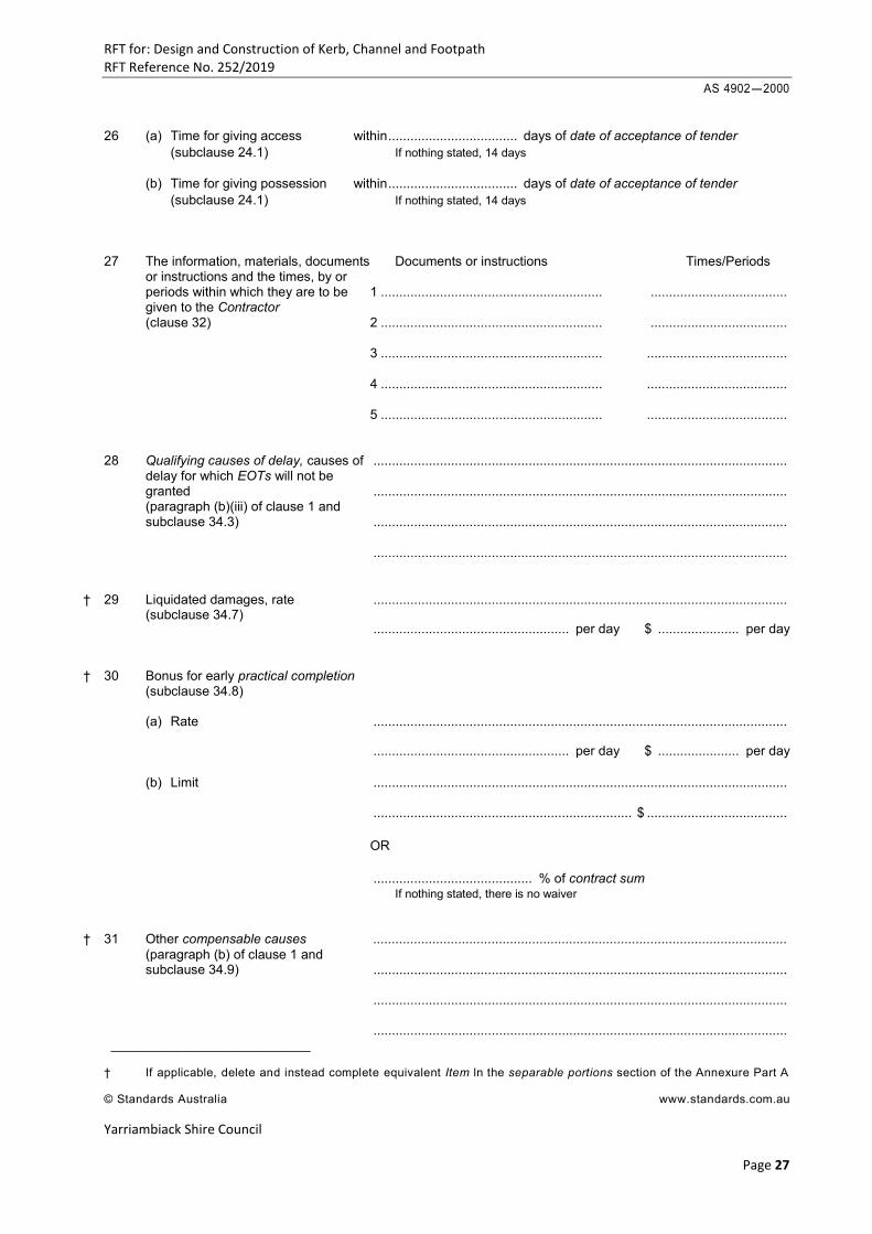
AS 4902-2000
26 (a) Time for giving access within ................................... days of date of acceptance of tender (subclause 24.1) If nothing stated, 14 days (b) Time for giving possession within ................................... days of date of acceptance of tender (subclause 24.1) If nothing stated, 14 days 27 The information, materials, documents Documents or instructions Times/Periods or instructions and the times, by or periods within which they are to be 1 ............................................................ ..................................... given to the Contractor (clause 32) 2 ............................................................ ..................................... 3 ............................................................ ...................................... 4 ............................................................ ...................................... 5 ............................................................ ...................................... 28 Qualifying causes of delay, causes of ................................................................................................................ delay for which EOTs will not be granted ................................................................................................................ (paragraph (b)(iii) of clause 1 and subclause 34.3) ................................................................................................................ ................................................................................................................
† 29 Liquidated damages, rate ................................................................................................................ (subclause 34.7)
..................................................... per day $ ...................... per day
† 30 Bonus for early practical completion (subclause 34.8) (a) Rate ................................................................................................................
..................................................... per day $ ...................... per day
(b) Limit ................................................................................................................
...................................................................... $ ...................................... OR ........................................... % of contract sum If nothing stated, there is no waiver
† 31 Other compensable causes ................................................................................................................ (paragraph (b) of clause 1 and subclause 34.9) ................................................................................................................ ................................................................................................................ ................................................................................................................
___________________________ † If applicable, delete and instead complete equivalent Item ln the separable portions section of the Annexure Part A © Standards Australia www.standards.com.au
RFT for: Design and Construction of Kerb, Channel and Footpath RFT Reference No. 252/2019
Yarriambiack Shire Council
Page 28
AS 4902-2000
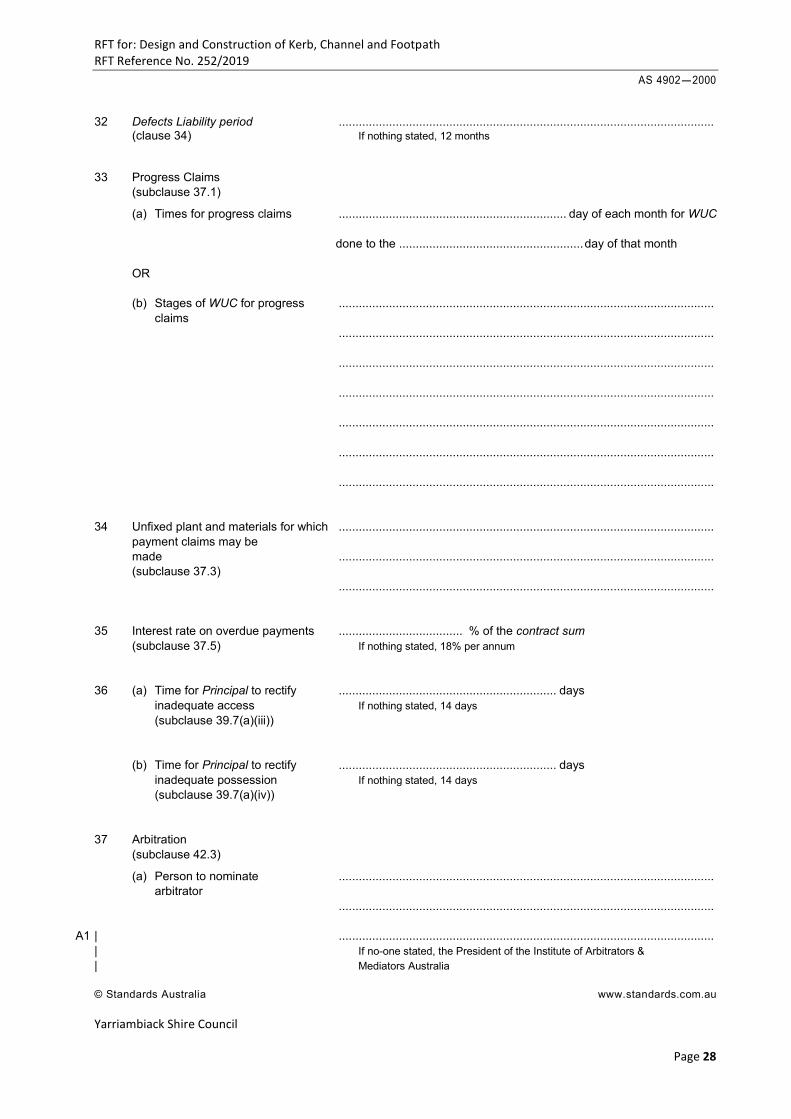
32 Defects Liability period ................................................................................................................ (clause 34) If nothing stated, 12 months 33 Progress Claims (subclause 37.1)
(a) Times for progress claims .................................................................... day of each month for WUC done to the ....................................................... day of that month OR (b) Stages of WUC for progress ................................................................................................................ claims ................................................................................................................ ................................................................................................................ ................................................................................................................ ................................................................................................................ ................................................................................................................ ................................................................................................................ 34 Unfixed plant and materials for which ................................................................................................................ payment claims may be made ................................................................................................................ (subclause 37.3) ................................................................................................................ 35 Interest rate on overdue payments ..................................... % of the contract sum (subclause 37.5) If nothing stated, 18% per annum 36 (a) Time for Principal to rectify ................................................................. days inadequate access If nothing stated, 14 days (subclause 39.7(a)(iii)) (b) Time for Principal to rectify ................................................................. days inadequate possession If nothing stated, 14 days (subclause 39.7(a)(iv)) 37 Arbitration (subclause 42.3)
(a) Person to nominate ................................................................................................................ arbitrator ................................................................................................................
A1 | ................................................................................................................ | If no-one stated, the President of the Institute of Arbitrators & | Mediators Australia
© Standards Australia www.standards.com.au
RFT for: Design and Construction of Kerb, Channel and Footpath RFT Reference No. 252/2019
Yarriambiack Shire Council
Page 29
AS 4902-2000
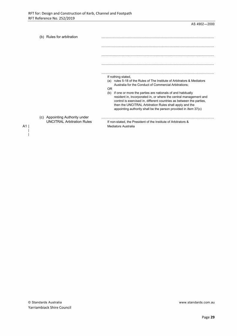
(b) Rules for arbitration ................................................................................................................ ................................................................................................................ ................................................................................................................ ................................................................................................................ ................................................................................................................ If nothing stated, (a) rules 5-18 of the Rules of The Institute of Arbitrators & Mediators Australia for the Conduct of Commercial Arbitrations; OR (b) if one or more the parties are nationals of and habitually
resident in, incorporated in, or where the central management and control is exercised in, different countries as between the parties, then the UNCITRAL Arbitration Rules shall apply and the appointing authority shall be the person provided in Item 37(c) (c) Appointing Authority under ................................................................................................................ UNCITRAL Arbitration Rules If non-stated, the President of the Institute of Arbitrators &
A1 | Mediators Australia | |
© Standards Australia www.standards.com.au
RFT for: Design and Construction of Kerb, Channel and Footpath RFT Reference No. 252/2019
Yarriambiack Shire Council
Page 30
AS 4902-2000
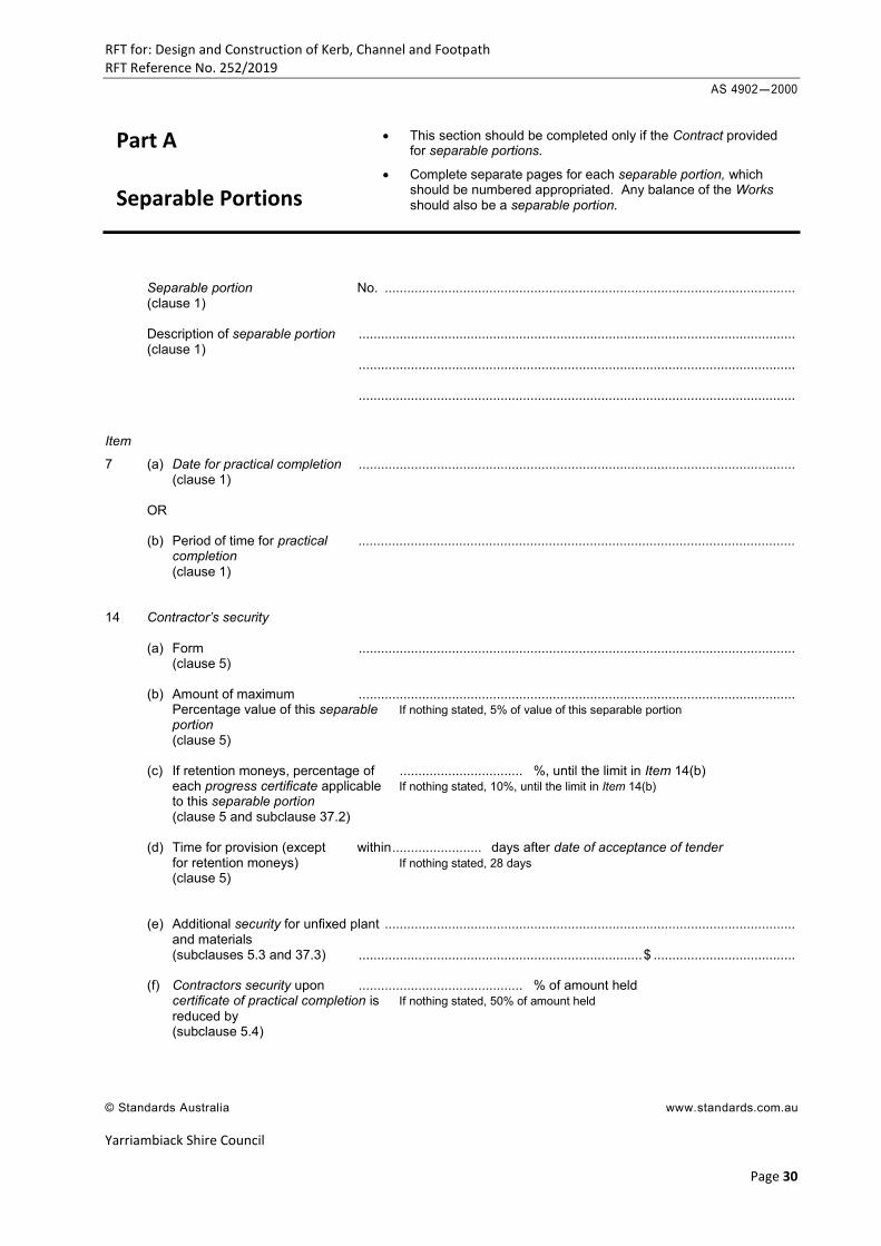
This section should be completed only if the Contract provided for separable portions.
Complete separate pages for each separable portion, which should be numbered appropriated. Any balance of the Works should also be a separable portion.
Separable portion No. .............................................................................................................. (clause 1) Description of separable portion ..................................................................................................................... (clause 1) ..................................................................................................................... ..................................................................................................................... Item
7 (a) Date for practical completion ..................................................................................................................... (clause 1) OR (b) Period of time for practical ..................................................................................................................... completion (clause 1) 14 Contractor’s security (a) Form ..................................................................................................................... (clause 5) (b) Amount of maximum ..................................................................................................................... Percentage value of this separable If nothing stated, 5% of value of this separable portion portion (clause 5) (c) If retention moneys, percentage of ................................. %, until the limit in Item 14(b) each progress certificate applicable If nothing stated, 10%, until the limit in Item 14(b) to this separable portion (clause 5 and subclause 37.2) (d) Time for provision (except within ........................ days after date of acceptance of tender for retention moneys) If nothing stated, 28 days (clause 5) (e) Additional security for unfixed plant .............................................................................................................. and materials (subclauses 5.3 and 37.3) ............................................................................ $ ...................................... (f) Contractors security upon ............................................ % of amount held certificate of practical completion is If nothing stated, 50% of amount held reduced by (subclause 5.4)
© Standards Australia www.standards.com.au
Part A Separable Portions
RFT for: Design and Construction of Kerb, Channel and Footpath RFT Reference No. 252/2019
Yarriambiack Shire Council
Page 31
AS 4902-2000
15 Principal’s security (a) Form ..................................................................................................................... (clause 5) (b) Amount of maximum ..................................................................................................................... percentage value of this If nothing stated, nil separable portion (clause 5) (c) Time for provision within ........................ days after date of acceptance of tender (clause 5) If nothing stated, 28 days (c) Principal’s security upon certificate ................................. % of amount held of practical completion is reduced If nothing stated, 10%, until the limit in Item 14(b) by (subclause 5.4) 29 Liquidated damages, rate ..................................................................................................................... (subclause 34.7) ......................................................... per day $ ...................... per day 30 Bonus for early practical completion (subclause 34.8)
(a) Rate ..................................................................................................................... ......................................................... per day $ ...................... per day (b) Limit ..................................................................................................................... ......................................................... per day $ ...................... per day OR ............................................ % of value of this separable portion If nothing stated, there is no waiver 31 Other compensable causes ..................................................................................................................... (paragraph (b) of clause 1 and subclause 34.9) ..................................................................................................................... ..................................................................................................................... .....................................................................................................................
© Standards Australia www.standards.com.au
RFT for: Design and Construction of Kerb, Channel and Footpath RFT Reference No. 252/2019
Yarriambiack Shire Council
Page 32
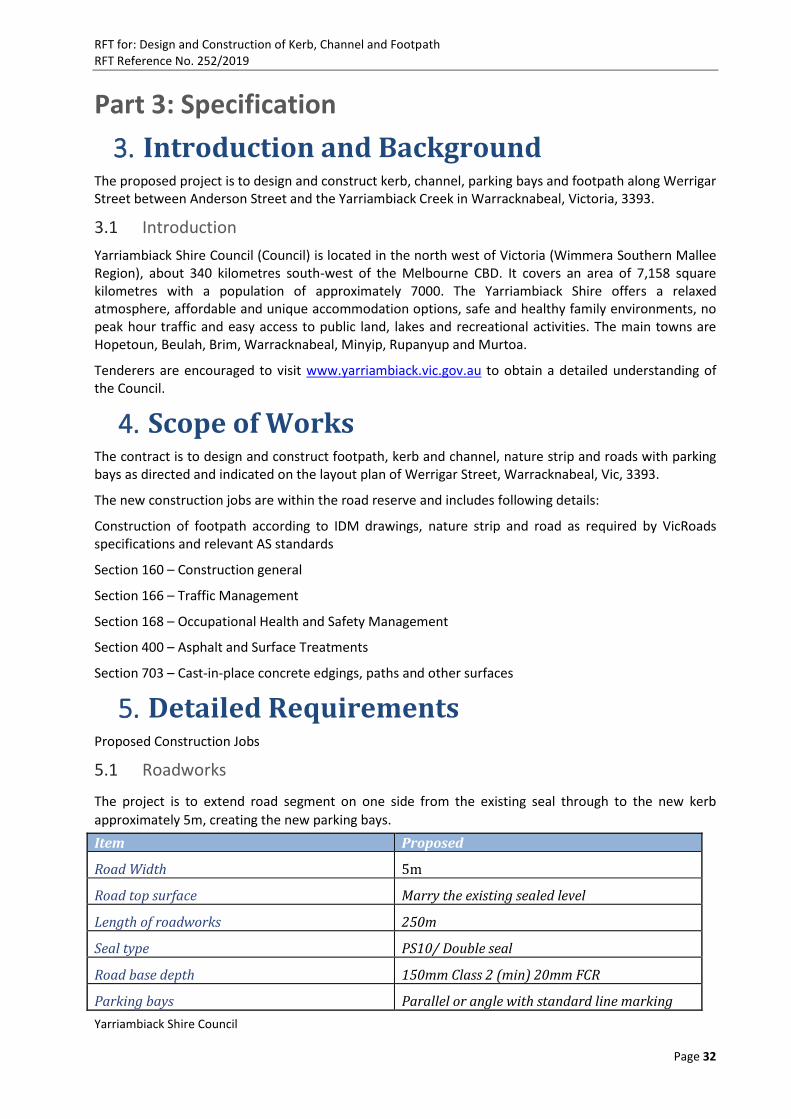
Part 3: Specification
3. Introduction and Background The proposed project is to design and construct kerb, channel, parking bays and footpath along Werrigar Street between Anderson Street and the Yarriambiack Creek in Warracknabeal, Victoria, 3393.
3.1 Introduction
Yarriambiack Shire Council (Council) is located in the north west of Victoria (Wimmera Southern Mallee Region), about 340 kilometres south-west of the Melbourne CBD. It covers an area of 7,158 square kilometres with a population of approximately 7000. The Yarriambiack Shire offers a relaxed atmosphere, affordable and unique accommodation options, safe and healthy family environments, no peak hour traffic and easy access to public land, lakes and recreational activities. The main towns are Hopetoun, Beulah, Brim, Warracknabeal, Minyip, Rupanyup and Murtoa.
Tenderers are encouraged to visit www.yarriambiack.vic.gov.au to obtain a detailed understanding of the Council.
4. Scope of Works The contract is to design and construct footpath, kerb and channel, nature strip and roads with parking bays as directed and indicated on the layout plan of Werrigar Street, Warracknabeal, Vic, 3393.
The new construction jobs are within the road reserve and includes following details:
Construction of footpath according to IDM drawings, nature strip and road as required by VicRoads specifications and relevant AS standards
Section 160 – Construction general
Section 166 – Traffic Management
Section 168 – Occupational Health and Safety Management
Section 400 – Asphalt and Surface Treatments
Section 703 – Cast-in-place concrete edgings, paths and other surfaces
5. Detailed Requirements Proposed Construction Jobs
5.1 Roadworks
The project is to extend road segment on one side from the existing seal through to the new kerb
approximately 5m, creating the new parking bays. Item Proposed
Road Width 5m
Road top surface Marry the existing sealed level
Length of roadworks 250m
Seal type PS10/ Double seal
Road base depth 150mm Class 2 (min) 20mm FCR
Parking bays Parallel or angle with standard line marking
RFT for: Design and Construction of Kerb, Channel and Footpath RFT Reference No. 252/2019
Yarriambiack Shire Council
Page 33
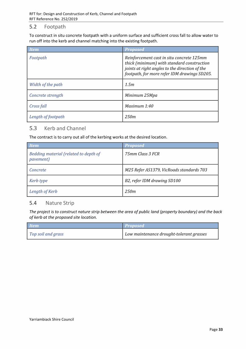
5.2 Footpath
To construct in situ concrete footpath with a uniform surface and sufficient cross fall to allow water to run off into the kerb and channel matching into the existing footpath.
Item Proposed
Footpath Reinforcement cast in situ concrete 125mm thick (minimum) with standard construction joints at right angles to the direction of the footpath, for more refer IDM drawings SD205.
Width of the path 1.5m
Concrete strength Minimum 25Mpa
Cross fall Maximum 1:40
Length of footpath 250m
5.3 Kerb and Channel
The contract is to carry out all of the kerbing works at the desired location.
Item Proposed
Bedding material (related to depth of pavement)
75mm Class 3 FCR
Concrete M25 Refer AS1379, VicRoads standards 703
Kerb type B2, refer IDM drawing SD100
Length of Kerb 250m
5.4 Nature Strip
The project is to construct nature strip between the area of public land (property boundary) and the back of kerb at the proposed site location.
Item Proposed
Top soil and grass Low maintenance drought-tolerant grasses

RFT for: Design and Construction of Kerb, Channel and Footpath RFT Reference No. 252/2019
Yarriambiack Shire Council
Page 34
6. Constructions requirements The construction site is as shown in the prosed drawing. It is required to complete all the works according to standards, VicRoads specifications and IDM drawings.
6.1 Planning phase
Prior to proceeding for construction, the contractor must submit preliminary design documents to the
Superintendent for approval. This includes close liaison with the relevant Council Officers in relation to
the design, development of preliminary design, and the submission of the preliminary design for sign-off
prior to the development of detailed design, and submission of proposed structures.
6.2 Detailed design plans and documentation phase
After the preliminary design has been accepted by the Superintendent, detailed plans, specifications and structural computations shall be prepared and submitted for approval. The detailed plans shall include, as a minimum, alignment plans, nature strip, sections details, etc. Allowance shall be made by the Contractor for an independent competent and experienced design engineer to check the computations of the proposed designed drawings.
Detailed plans shall be provided in the electronic formats that are compatible with pdf viewer and AutoCAD 2015 for Council records.
All other documents shall be provided in .pdf and .docx format for Council records.
6.3 Construction phase
The contractor shall submit a timetable for the project and duration for each phase that meets the requirement of Schedule 1.
A quality assurance file of the project must be maintained by the contractor, and submitted to the Manager of Asset Operations at the completion of the construction phase. Access to the quality assurance file shall be provided by the Contractor to the Manager of Asset Operations at all times during the course of the project.
The Contractor shall have on-site as a minimum the following documents:
A copy of signed contract agreement, detailed design drawings and specifications
Copies of all certificates of insurance
Records of all inspections and results of materials tests
Daily diary and contractor’s Quality Assurance documents
Evidence of compliance with Contractor’s quality system
Contractor’s OH&S plan
Job Safety Analysis (JSAs) for each construction activity and any Safe Work Method Statements (SWMS) being used.
6.4 Commissioning Phase
The contractor shall be required to allow for formal commissioning of the structure prior to the opening of the structure for use by the public.
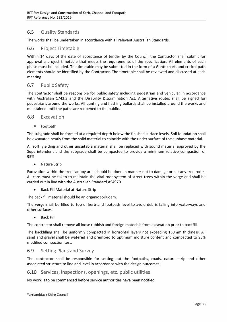
RFT for: Design and Construction of Kerb, Channel and Footpath RFT Reference No. 252/2019
Yarriambiack Shire Council
Page 35
6.5 Quality Standards
The works shall be undertaken in accordance with all relevant Australian Standards.
6.6 Project Timetable
Within 14 days of the date of acceptance of tender by the Council, the Contractor shall submit for approval a project timetable that meets the requirements of the specification. All elements of each phase must be included. The timetable may be submitted in the form of a Gantt chart, and critical path elements should be identified by the Contractor. The timetable shall be reviewed and discussed at each meeting.
6.7 Public Safety
The contractor shall be responsible for public safety including pedestrian and vehicular in accordance with Australian 1742.3 and the Disability Discrimination Act. Alternative routes shall be signed for pedestrians around the works. All bunting and flashing bollards shall be installed around the works and maintained until the paths are reopened to the public.
6.8 Excavation
Footpath
The subgrade shall be formed at a required depth below the finished surface levels. Soil foundation shall be excavated neatly from the solid material to coincide with the under surface of the subbase material.
All soft, yielding and other unsuitable material shall be replaced with sound material approved by the Superintendent and the subgrade shall be compacted to provide a minimum relative compaction of 95%.
Nature Strip
Excavation within the tree canopy area should be done in manner not to damage or cut any tree roots. All care must be taken to maintain the vital root system of street trees within the verge and shall be carried out in line with the Australian Standard AS4970.
Back Fill Material at Nature Strip
The back fill material should be an organic soil/loam.
The verge shall be filled to top of kerb and footpath level to avoid debris falling into waterways and other surfaces.
Back Fill
The contractor shall remove all loose rubbish and foreign materials from excavation prior to backfill.
The backfilling shall be uniformly compacted in horizontal layers not exceeding 150mm thickness. All sand and gravel shall be watered and premixed to optimum moisture content and compacted to 95% modified compaction test.
6.9 Setting Plans and Survey
The contractor shall be responsible for setting out the footpaths, roads, nature strip and other associated structure to line and level in accordance with the design outcomes.
6.10 Services, inspections, openings, etc. public utilities
No work is to be commenced before service authorities have been notified.
RFT for: Design and Construction of Kerb, Channel and Footpath RFT Reference No. 252/2019
Yarriambiack Shire Council
Page 36
The contractor must aware of the locations of water and sewer mains, as well as storm water, pipe drains, power, communications and any other authorities mains and services that may be in the vicinity of the site of works.
The contractor shall be responsible for any damage done to any services, private or Council properties, etc. sustained as a result of the works. The Council may repair any Council infrastructure damaged by the contractor and recover the associated costs from the contractor.
6.11 Contract Documents
The contract documents will comprise:
Letter of Acceptance
Contract Agreement
Condition of Contract AS4902 Annexure A
Form of tender
Specification
Location or Indicative drawing (provided by Council)
Relevant IDM Drawings and Design Checklist
Australian Standard/s and VicRoads Specifications
Programme of work submitted by the Contractor
Contractor’s Risk Management Plan
Any further information that was submitted by the Contractor as part of its tender
Any specifications and documentation submitted by the Contractor over the course of the project
6.12 Environmental Management Plan
The successful Tenderer shall include a Quality System covering environmental management incorporating an element to manage the environmental effects of the work. This element shall consist of an environmental management plan that considers, but is not necessary confined to air pollution, water pollution, noise, waste, soil contamination, preservation of habitat and identified historic and archaeological sites.
The plan should be developed with reference to the ‘Environmental Protection Act 1970’ to manage all identified impacts and environmental protection requirements for the works. These procedures shall include inspection and test plans and checklists.
These procedures may include but are not limited to:
Flora and Fauna
Cultural Heritage
Noise Pollution
Community Relations
Soil Management
Vibration
Air quality
Waste management or minimisation
Water pollution
RFT for: Design and Construction of Kerb, Channel and Footpath RFT Reference No. 252/2019
Yarriambiack Shire Council
Page 37
Ground water
Concrete prime and bitumen
Sediment control
Resources (products and materials).
6.13 Temporary Services
The successful Tenderer shall provide all necessary services and facilities during the construction period to the approval of all relevant authorities, including:
Amenities
Water
Electric Power
Sheds
Scaffolding, etc.
The connections, bills or other expenses are managed by the Contractor. The contractor shall provide temporary sanity accommodation on site. The Contractor is responsible to remove all temporary services at the completion of the Contract.
6.14 Site meetings
The successful Tenderer and representatives of the principal shall meet on site at regular intervals to discuss the works and the successful Tenderer shall arrange for the attendance of such sub-contractor or suppliers as may be required.
6.15 Inspections
Where the Contractor requires notice of inspection to be given in respect of any part of the works, that part of the works shall not have further work placed thereon or be covered up or put out of view without the prior approval of the Principal.
The Contractor shall inform the Principal (giving not less than two day’s notice) when the works reach any of the following stages, and should the Principal wish to inspect the work, do so before any further works are carried out, provide the attendance herein after specified:-
Detailed design review
Construction program
o Concreting
o Base, sub-base works
o Proof rolling
o Any tests (strength test, moisture test, density test, etc.)
o Surface preparations
o Any hold points in the specification.
6.16 Variations
Action on variations shall be in accordance with clause 36 – General Conditions of Contract.
Code of practice and VIBA
The Contractor must comply with the Victorian Government Code of Practice for the Building, and Construction Industry, and the Victorian Building Industry Agreement, 1996 (where applicable).
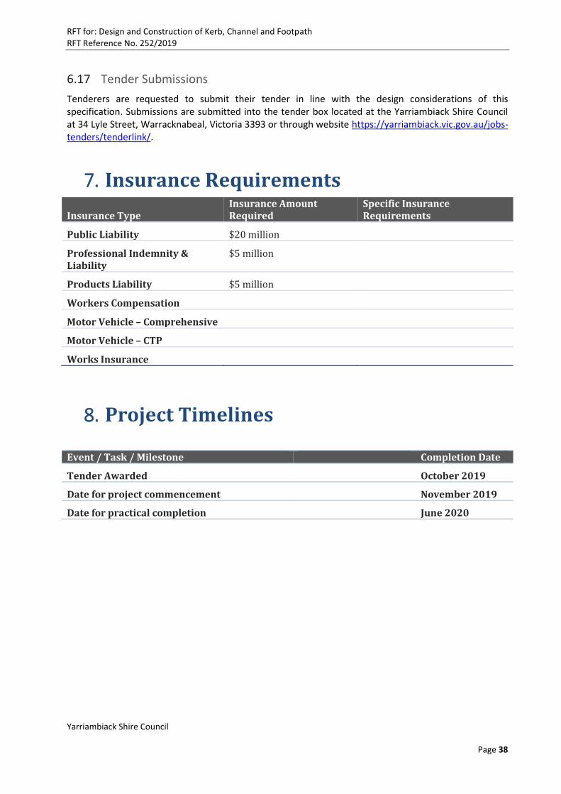
RFT for: Design and Construction of Kerb, Channel and Footpath RFT Reference No. 252/2019
Yarriambiack Shire Council
Page 38
6.17 Tender Submissions
Tenderers are requested to submit their tender in line with the design considerations of this specification. Submissions are submitted into the tender box located at the Yarriambiack Shire Council at 34 Lyle Street, Warracknabeal, Victoria 3393 or through website https://yarriambiack.vic.gov.au/jobs-tenders/tenderlink/.
7. Insurance Requirements
Insurance Type Insurance Amount Required
Specific Insurance Requirements
Public Liability $20 million
Professional Indemnity & Liability
$5 million
Products Liability $5 million
Workers Compensation
Motor Vehicle – Comprehensive
Motor Vehicle – CTP
Works Insurance
8. Project Timelines
Event / Task / Milestone Completion Date
Tender Awarded October 2019
Date for project commencement November 2019
Date for practical completion June 2020

RFT for: Design and Construction of Kerb, Channel and Footpath RFT Reference No. 252/2019
Yarriambiack Shire Council
Page 39
Part 4: Response Schedules
Instructions to Tenderers
Format of Tender
The Tenderer is to complete the response schedules (Part 4) in the fields as indicated and retain the same format as provided by the Council. Tenderers must respond to the requirements in the Specification (Part 3) and Proposed Conditions of Contract (Part 2) in accordance with the Conditions of Tendering (Part 1) of this RFT.
Any attachments, supplementary material, graphics or data should be attached at the end of this document and referenced to the relevant field/section of this template.
Notes Regarding Responding to this RFT
Before responding to the evaluation criteria, Tenderers must note the following:
o All information relevant to your answers to each criterion are to be contained within your Tender;
o Tenderers are to assume that the Evaluation Panel has no previous knowledge of the Tenderers organisation, activities or experience.
o The responses provided form part of the Council’s Tender evaluation assessment and are to be completed by Tenderers.
Tenders that do not satisfy criterion identified as Mandatory Compliance Criteria will be deemed non-compliant and excluded from further participation in the evaluation process.
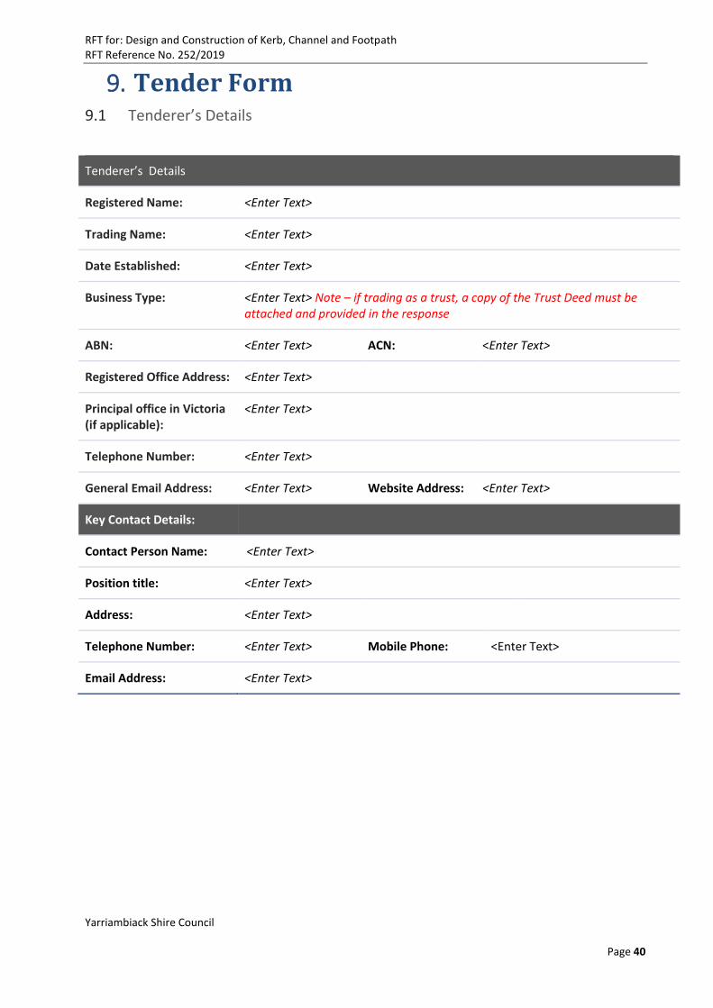
RFT for: Design and Construction of Kerb, Channel and Footpath RFT Reference No. 252/2019
Yarriambiack Shire Council
Page 40
9. Tender Form 9.1 Tenderer’s Details
Tenderer’s Details
Registered Name: <Enter Text>
Trading Name: <Enter Text>
Date Established: <Enter Text>
Business Type: <Enter Text> Note – if trading as a trust, a copy of the Trust Deed must be attached and provided in the response
ABN: <Enter Text> ACN: <Enter Text>
Registered Office Address: <Enter Text>
Principal office in Victoria (if applicable):
<Enter Text>
Telephone Number: <Enter Text>
General Email Address: <Enter Text> Website Address: <Enter Text>
Key Contact Details:
Contact Person Name: <Enter Text>
Position title: <Enter Text>
Address: <Enter Text>
Telephone Number: <Enter Text> Mobile Phone: <Enter Text>
Email Address: <Enter Text>

RFT for: Design and Construction of Kerb, Channel and Footpath RFT Reference No. 252/2019
Yarriambiack Shire Council
Page 41
9.2 Tenderer’s Declaration
Tenderer’s Declaration
Tenderers are to sign and return this declaration. A digitally signed document or image of the signatures will suffice.
The Tenderer warrants that it has the full set of RFT documents as follows:
Part 1 – Conditions of Tendering
Part 2 – Proposed Conditions of Contract
Part 3 – Specification
Part 4 – Response Schedules
and Addenda
Please list addenda numbers or ‘N/A’ (please delete this note prior to submission)
By signing below, the Tenderer confirms that the information provided in this Tender is true, correct and complete: Signed for and on behalf of the Tenderer:
Tenderer:
Name:
Position:
Address:
Signature of Tenderer’s authorised officer:
Date of signing:
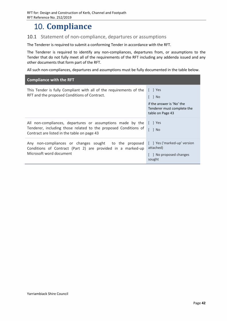
RFT for: Design and Construction of Kerb, Channel and Footpath RFT Reference No. 252/2019
Yarriambiack Shire Council
Page 42
10. Compliance 10.1 Statement of non-compliance, departures or assumptions
The Tenderer is required to submit a conforming Tender in accordance with the RFT.
The Tenderer is required to identify any non-compliances, departures from, or assumptions to the Tender that do not fully meet all of the requirements of the RFT including any addenda issued and any other documents that form part of the RFT.
All such non-compliances, departures and assumptions must be fully documented in the table below.
Compliance with the RFT
This Tender is fully Compliant with all of the requirements of the RFT and the proposed Conditions of Contract.
[ ] Yes
[ ] No
if the answer is ‘No’ the Tenderer must complete the table on Page 43
All non-compliances, departures or assumptions made by the Tenderer, including those related to the proposed Conditions of Contract are listed in the table on page 43
[ ] Yes
[ ] No
Any non-compliances or changes sought to the proposed Conditions of Contract (Part 2) are provided in a marked-up Microsoft word document
[ ] Yes (‘marked-up’ version attached)
[ ] No proposed changes sought
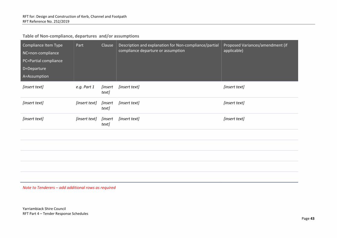
RFT for: Design and Construction of Kerb, Channel and Footpath RFT Reference No. 252/2019
Yarriambiack Shire Council RFT Part 4 – Tender Response Schedules
Page 43
Table of Non-compliance, departures and/or assumptions
Compliance Item Type
NC=non-compliance
PC=Partial compliance
D=Departure
A=Assumption
Part Clause Description and explanation for Non-compliance/partial compliance departure or assumption
Proposed Variances/amendment (if applicable)
[insert text] e.g. Part 1 [insert text]
[insert text] [insert text]
[insert text] [insert text] [insert text]
[insert text] [insert text]
[insert text] [insert text] [insert text]
[insert text] [insert text]
Note to Tenderers – add additional rows as required
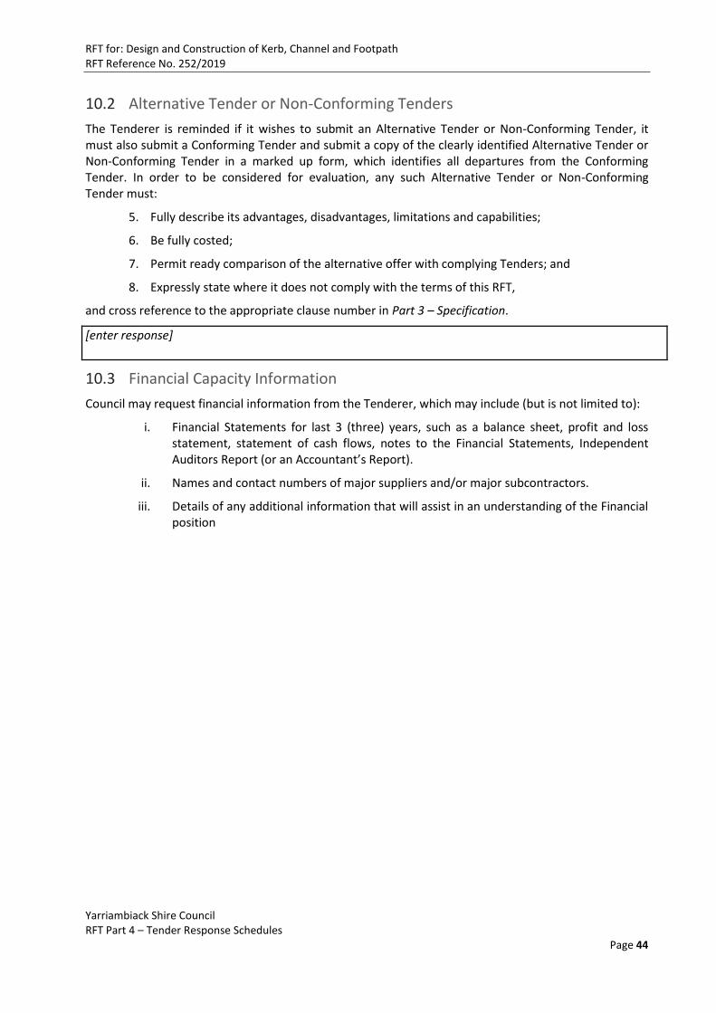
RFT for: Design and Construction of Kerb, Channel and Footpath RFT Reference No. 252/2019
Yarriambiack Shire Council RFT Part 4 – Tender Response Schedules
Page 44
10.2 Alternative Tender or Non-Conforming Tenders
The Tenderer is reminded if it wishes to submit an Alternative Tender or Non-Conforming Tender, it must also submit a Conforming Tender and submit a copy of the clearly identified Alternative Tender or Non-Conforming Tender in a marked up form, which identifies all departures from the Conforming Tender. In order to be considered for evaluation, any such Alternative Tender or Non-Conforming Tender must:
5. Fully describe its advantages, disadvantages, limitations and capabilities;
6. Be fully costed;
7. Permit ready comparison of the alternative offer with complying Tenders; and
8. Expressly state where it does not comply with the terms of this RFT,
and cross reference to the appropriate clause number in Part 3 – Specification.
[enter response]
10.3 Financial Capacity Information
Council may request financial information from the Tenderer, which may include (but is not limited to):
i. Financial Statements for last 3 (three) years, such as a balance sheet, profit and loss statement, statement of cash flows, notes to the Financial Statements, Independent Auditors Report (or an Accountant’s Report).
ii. Names and contact numbers of major suppliers and/or major subcontractors.
iii. Details of any additional information that will assist in an understanding of the Financial position

RFT for: Design and Construction of Kerb, Channel and Footpath RFT Reference No. 252/2019
Yarriambiack Shire Council RFT Part 4 – Tender Response Schedules
Page 45
10.4 Current Insurance Certificates
Meeting the Council’s insurance requirements is a mandatory criterion. Please provide detail of insurance coverage as required in the table below against each of the insurance requirements detailed. The levels of cover detailed are the minimum acceptable levels of cover and will be required to be maintained for the term set out in the Conditions of Contract.
Please also submit as an attachment current Certificates of Currency for the Insurances detailed below
Insurance Type Minimum Insurance Amount Required
Specific Insurance Requirements
Name of Insurer
Insured Amount
Policy Number
Policy Expiration Copy of Certificate of Currency Attached? (Y/N)
Council Requirements Tenderers to Complete
Public Liability Minimum cover $20million
Professional Indemnity & Liability
Minimum cover $5million
Products Liability Minimum cover $5million
Workers Compensation
As required by law
Works Insurance
[Insert rows as required]
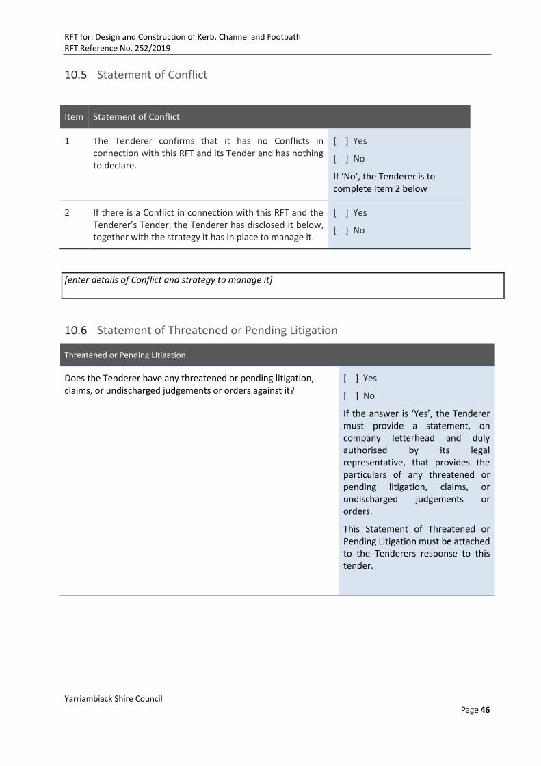
RFT for: Design and Construction of Kerb, Channel and Footpath RFT Reference No. 252/2019
Yarriambiack Shire Council Page 46
10.5 Statement of Conflict
Item Statement of Conflict
1 The Tenderer confirms that it has no Conflicts in connection with this RFT and its Tender and has nothing to declare.
[ ] Yes
[ ] No
If ‘No’, the Tenderer is to complete Item 2 below
2 If there is a Conflict in connection with this RFT and the Tenderer’s Tender, the Tenderer has disclosed it below, together with the strategy it has in place to manage it.
[ ] Yes
[ ] No
[enter details of Conflict and strategy to manage it]
10.6 Statement of Threatened or Pending Litigation
Threatened or Pending Litigation
Does the Tenderer have any threatened or pending litigation, claims, or undischarged judgements or orders against it?
[ ] Yes
[ ] No
If the answer is ‘Yes’, the Tenderer must provide a statement, on company letterhead and duly authorised by its legal representative, that provides the particulars of any threatened or pending litigation, claims, or undischarged judgements or orders.
This Statement of Threatened or Pending Litigation must be attached to the Tenderers response to this tender.

RFT for: Design and Construction of Kerb, Channel and Footpath RFT Reference No. 252/2019
Yarriambiack Shire Council Page 47
10.7 Compliance with legislation, relevant regulations and codes
Compliance with legislation, relevant regulations and codes
Has the Tenderer been in default of any fine issued for a breach of legislation, including OH&S or Environmental legislation, regulations or requirements and/or served with a notice in the last five (5) years?
[ ] Yes
[ ] No
if ‘Yes’ please provide details of the breach in the response area provided below
[provide details of any recent breaches, prosecution or fines]
11. Occupational Health and Safety Management
11.1 OH&S Systems, Policies and Management
OH&S Systems, Policies and Management
Does the Tenderer have a third party accredited OH&S management system?
[ ] Yes
[ ] No
if ‘Yes’, please provide details of the accreditation in the response area provided below and attach a copy of the current certification
If you answered ‘no’ to the above, does the Tenderer have OHS management system?
[ ] Yes
[ ] No
if ‘Yes’, please provide details of the accreditation in the response area provided below
Does the Tenderer have a current OHS Policy? [ ] Yes
[ ] No
Does the Tenderer have OHS training strategy for all employees? [ ] Yes
[ ] No

RFT for: Design and Construction of Kerb, Channel and Footpath RFT Reference No. 252/2019
Yarriambiack Shire Council Page 48
OH&S Systems, Policies and Management (cont)
Are specific OH&S responsibilities clearly assigned to employees or sub-contractors involved with the planning, supervision and execution of works and services?
[ ] Yes
[ ] No
If ‘Yes’ provide details of your reporting & investigation procedures in the response area below or submit a copy of your Standard Incident Report Form.
Does the Tenderer have a process for OHS hazard identification, assessment, investigation and control?
[ ] Yes
[ ] No
Has the Tenderer identified the risks associated with its routine operations and developed standard operating procedures or safe systems of work to minimize or eliminate those risks?
[ ] Yes
[ ] No
If ‘Yes’ provide/attach a summary listing of procedures or work instructions
[enter additional details of OH&S Systems]

RFT for: Design and Construction of Kerb, Channel and Footpath RFT Reference No. 252/2019
Yarriambiack Shire Council Page 49
12. Quality Management
Quality Management System
Does the Tenderer have a current certification of its Quality Management System to AS/NZS ISO 9001:2008?
[ ] Yes
[ ] No
If the answer is ‘Yes’, please provide as an attachment, a copy of your current certificate of certification. If ‘no’, please complete the next question
Quality Management Systems
Does the Tenderer have any documented Quality Management System or quality assurance systems implemented?
[ ] Yes
[ ] No
If the answer is ‘Yes’, please provide details in the area provided below.
[enter additional details of Quality Management Systems]
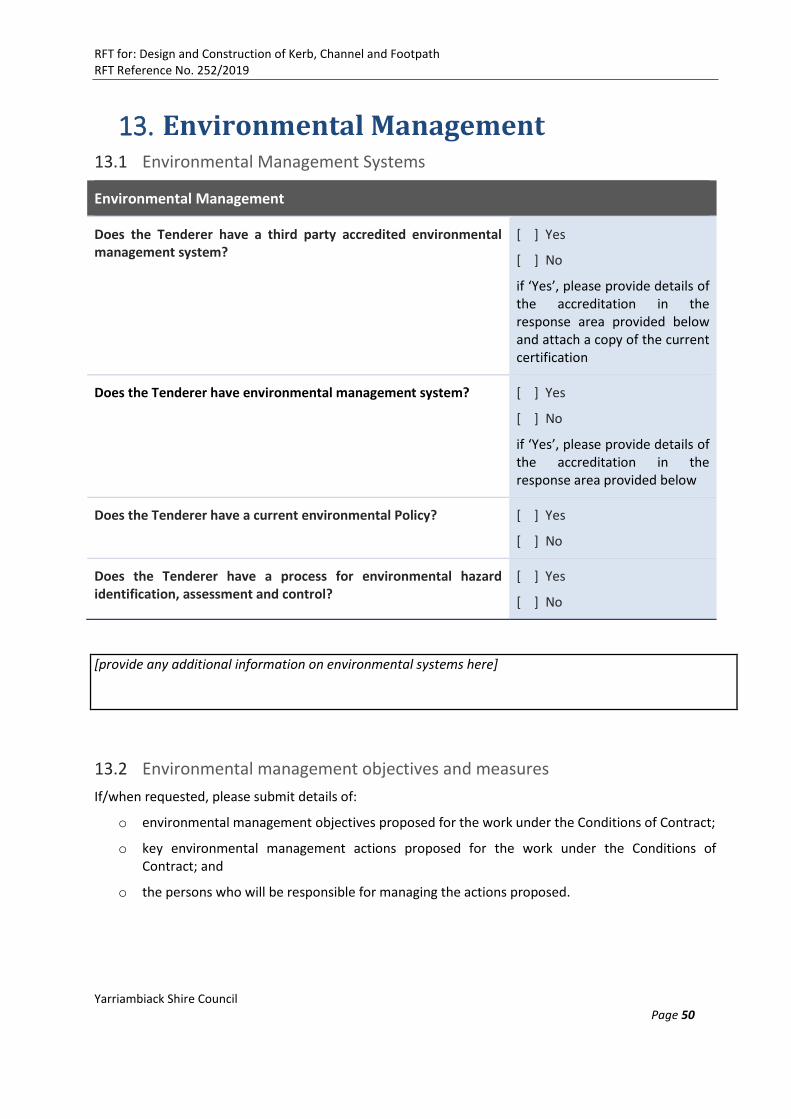
RFT for: Design and Construction of Kerb, Channel and Footpath RFT Reference No. 252/2019
Yarriambiack Shire Council Page 50
13. Environmental Management 13.1 Environmental Management Systems
Environmental Management
Does the Tenderer have a third party accredited environmental management system?
[ ] Yes
[ ] No
if ‘Yes’, please provide details of the accreditation in the response area provided below and attach a copy of the current certification
Does the Tenderer have environmental management system?
[ ] Yes
[ ] No
if ‘Yes’, please provide details of the accreditation in the response area provided below
Does the Tenderer have a current environmental Policy? [ ] Yes
[ ] No
Does the Tenderer have a process for environmental hazard identification, assessment and control?
[ ] Yes
[ ] No
[provide any additional information on environmental systems here]
13.2 Environmental management objectives and measures
If/when requested, please submit details of:
o environmental management objectives proposed for the work under the Conditions of Contract;
o key environmental management actions proposed for the work under the Conditions of Contract; and
o the persons who will be responsible for managing the actions proposed.
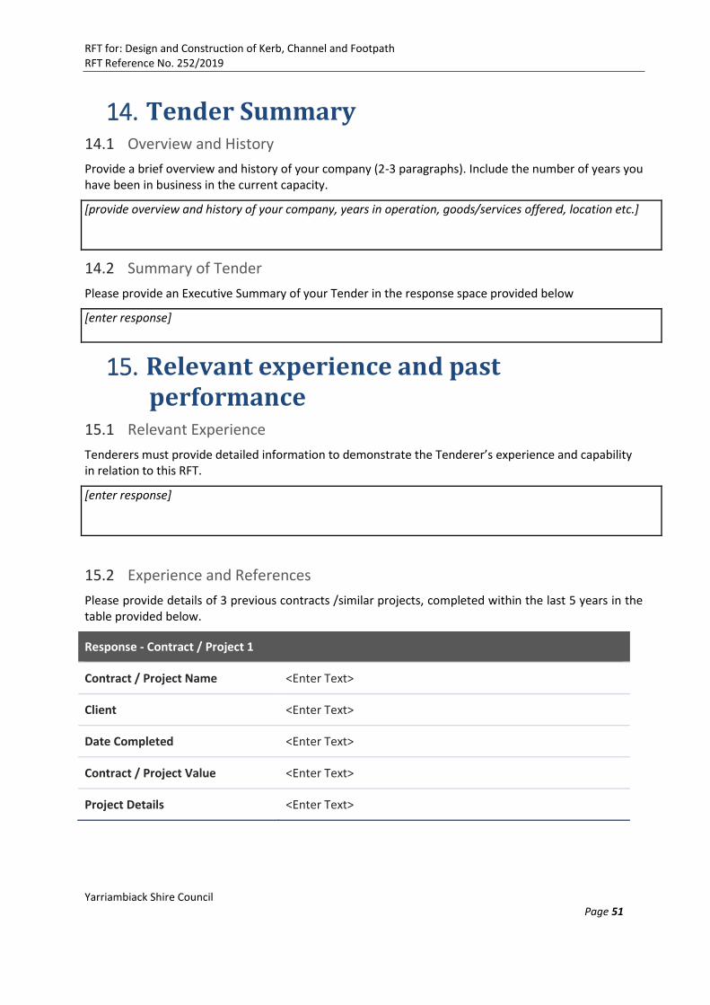
RFT for: Design and Construction of Kerb, Channel and Footpath RFT Reference No. 252/2019
Yarriambiack Shire Council Page 51
14. Tender Summary 14.1 Overview and History
Provide a brief overview and history of your company (2-3 paragraphs). Include the number of years you have been in business in the current capacity.
[provide overview and history of your company, years in operation, goods/services offered, location etc.]
14.2 Summary of Tender
Please provide an Executive Summary of your Tender in the response space provided below
[enter response]
15. Relevant experience and past performance
15.1 Relevant Experience
Tenderers must provide detailed information to demonstrate the Tenderer’s experience and capability in relation to this RFT.
[enter response]
15.2 Experience and References
Please provide details of 3 previous contracts /similar projects, completed within the last 5 years in the table provided below.
Response - Contract / Project 1
Contract / Project Name <Enter Text>
Client <Enter Text>
Date Completed <Enter Text>
Contract / Project Value <Enter Text>
Project Details <Enter Text>
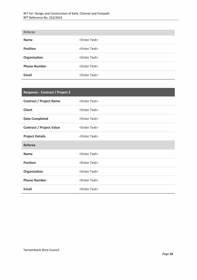
RFT for: Design and Construction of Kerb, Channel and Footpath RFT Reference No. 252/2019
Yarriambiack Shire Council Page 52
Referee
Name <Enter Text>
Position <Enter Text>
Organisation <Enter Text>
Phone Number <Enter Text>
Email <Enter Text>
Response - Contract / Project 2
Contract / Project Name <Enter Text>
Client <Enter Text>
Date Completed <Enter Text>
Contract / Project Value <Enter Text>
Project Details <Enter Text>
Referee
Name <Enter Text>
Position <Enter Text>
Organisation <Enter Text>
Phone Number <Enter Text>
Email <Enter Text>
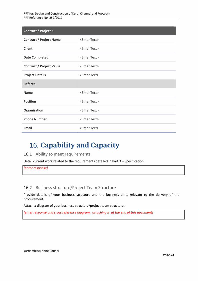
RFT for: Design and Construction of Kerb, Channel and Footpath RFT Reference No. 252/2019
Yarriambiack Shire Council Page 53
Contract / Project 3
Contract / Project Name <Enter Text>
Client <Enter Text>
Date Completed <Enter Text>
Contract / Project Value <Enter Text>
Project Details <Enter Text>
Referee
Name <Enter Text>
Position <Enter Text>
Organisation <Enter Text>
Phone Number <Enter Text>
Email <Enter Text>
16. Capability and Capacity 16.1 Ability to meet requirements
Detail current work related to the requirements detailed in Part 3 – Specification.
[enter response]
16.2 Business structure/Project Team Structure
Provide details of your business structure and the business units relevant to the delivery of the procurement.
Attach a diagram of your business structure/project team structure.
[enter response and cross reference diagram, attaching it at the end of this document]
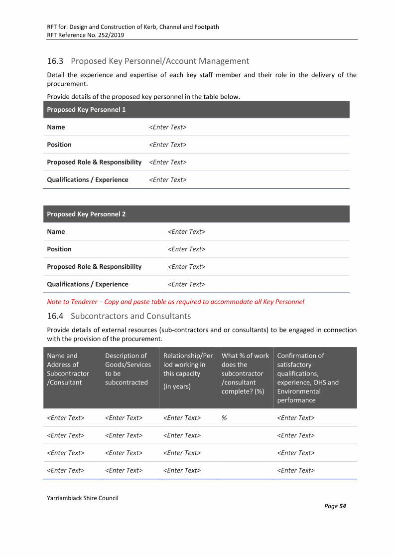
RFT for: Design and Construction of Kerb, Channel and Footpath RFT Reference No. 252/2019
Yarriambiack Shire Council Page 54
16.3 Proposed Key Personnel/Account Management
Detail the experience and expertise of each key staff member and their role in the delivery of the procurement.
Provide details of the proposed key personnel in the table below.
Proposed Key Personnel 1
Name <Enter Text>
Position <Enter Text>
Proposed Role & Responsibility <Enter Text>
Qualifications / Experience <Enter Text>
Proposed Key Personnel 2
Name <Enter Text>
Position <Enter Text>
Proposed Role & Responsibility <Enter Text>
Qualifications / Experience <Enter Text>
Note to Tenderer – Copy and paste table as required to accommodate all Key Personnel
16.4 Subcontractors and Consultants
Provide details of external resources (sub-contractors and or consultants) to be engaged in connection with the provision of the procurement.
Name and Address of Subcontractor /Consultant
Description of Goods/Services to be subcontracted
Relationship/Period working in this capacity
(in years)
What % of work does the subcontractor /consultant complete? (%)
Confirmation of satisfactory qualifications, experience, OHS and Environmental performance
<Enter Text> <Enter Text> <Enter Text> % <Enter Text>
<Enter Text> <Enter Text> <Enter Text> <Enter Text>
<Enter Text> <Enter Text> <Enter Text> <Enter Text>
<Enter Text> <Enter Text> <Enter Text> <Enter Text>

RFT for: Design and Construction of Kerb, Channel and Footpath RFT Reference No. 252/2019
Yarriambiack Shire Council Page 55
16.5 Proposed Subcontractor / Consultant Management Methodology
Please provide detail of your methodology to manage the proposed subcontractors / consultant in the response space provided below.
[enter response]
17. Delivery Methodology and Project / Implementation Plan
17.1 Methodology Provide details of the methodology proposed to be used in the provision of the Goods and/or Services. Detail timelines, methodology, delivery method, resources etc.
[enter response]
17.2 Project/Implementation Plan
Submit a program in MS Project or in the form of a bar chart or network diagram detailing key milestones and dates to satisfy the contract / project over its complete term.
The program is to be attached to the Tender response.
[enter reference to attachment]
18. Performance Management
18.1 Performance Benchmarking/Key performance Indicators Provide details of how you would propose that your performance be monitored (whether by yourself and / or by the Council), and what internal measures and benchmarks are in place?
[enter response]
18.2 Risk Management
Provide a Risk Management Plan to identify risk areas, processes; activities etc. to ensure policies, systems, practices are in place as to manage risks associated with the Goods and/or Services.
The Risk Management Plan is to be attached to the Tender response.
Provide details of your project delivery risk management strategies and practices that would be applicable in the context of this procurement.
[enter response]
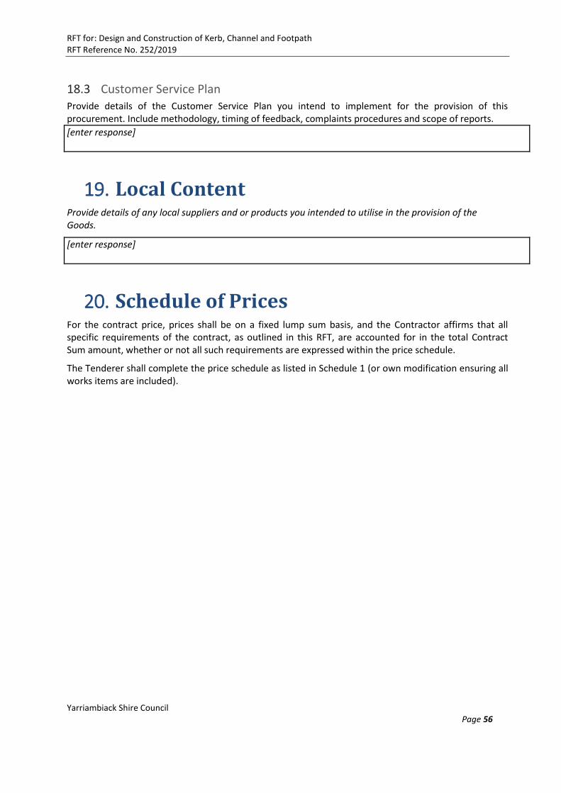
RFT for: Design and Construction of Kerb, Channel and Footpath RFT Reference No. 252/2019
Yarriambiack Shire Council Page 56
18.3 Customer Service Plan Provide details of the Customer Service Plan you intend to implement for the provision of this procurement. Include methodology, timing of feedback, complaints procedures and scope of reports.
[enter response]
19. Local Content Provide details of any local suppliers and or products you intended to utilise in the provision of the Goods.
[enter response]
20. Schedule of Prices For the contract price, prices shall be on a fixed lump sum basis, and the Contractor affirms that all specific requirements of the contract, as outlined in this RFT, are accounted for in the total Contract Sum amount, whether or not all such requirements are expressed within the price schedule.
The Tenderer shall complete the price schedule as listed in Schedule 1 (or own modification ensuring all works items are included).
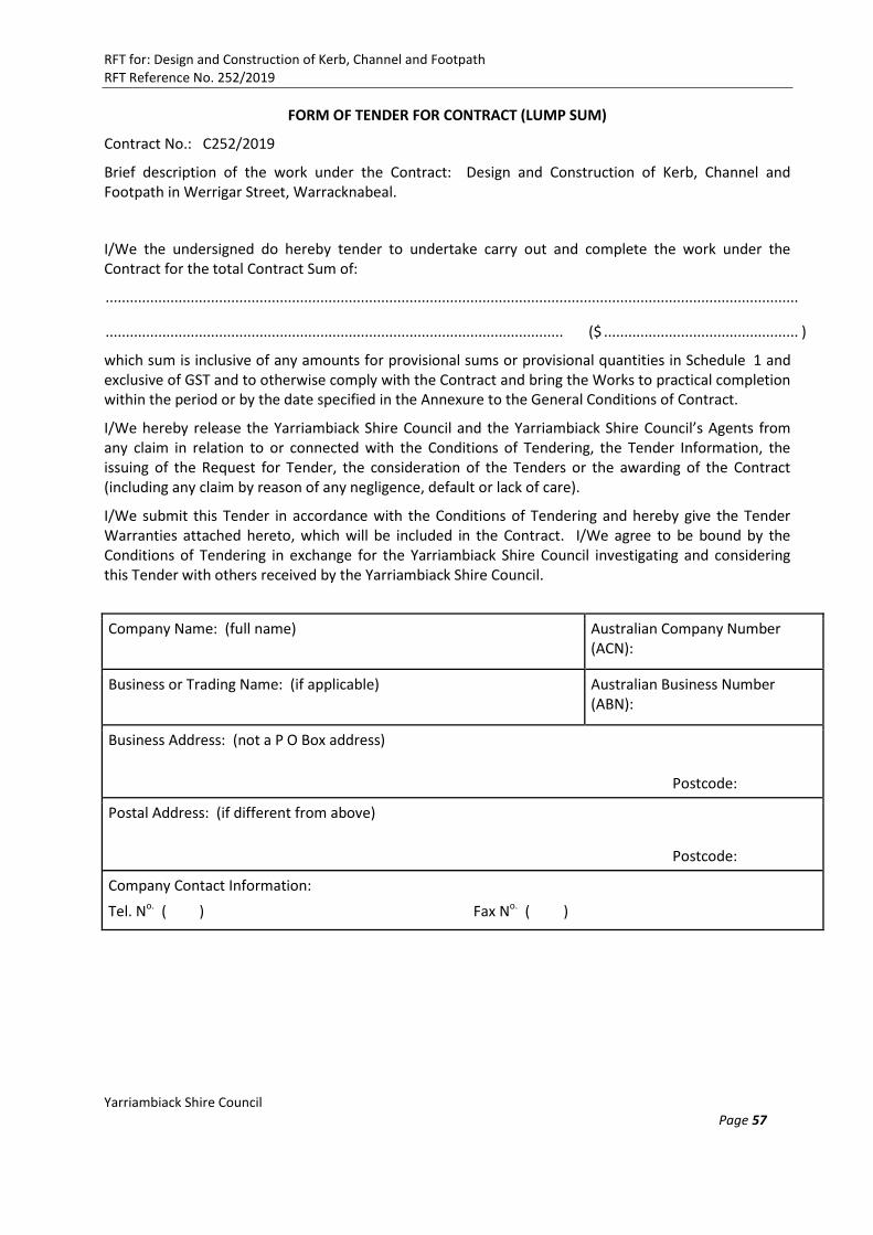
RFT for: Design and Construction of Kerb, Channel and Footpath RFT Reference No. 252/2019
Yarriambiack Shire Council Page 57
FORM OF TENDER FOR CONTRACT (LUMP SUM)
Contract No.: C252/2019
Brief description of the work under the Contract: Design and Construction of Kerb, Channel and Footpath in Werrigar Street, Warracknabeal.
I/We the undersigned do hereby tender to undertake carry out and complete the work under the Contract for the total Contract Sum of:
...........................................................................................................................................................................
................................................................................................................. ($ ................................................ )
which sum is inclusive of any amounts for provisional sums or provisional quantities in Schedule 1 and exclusive of GST and to otherwise comply with the Contract and bring the Works to practical completion within the period or by the date specified in the Annexure to the General Conditions of Contract.
I/We hereby release the Yarriambiack Shire Council and the Yarriambiack Shire Council’s Agents from any claim in relation to or connected with the Conditions of Tendering, the Tender Information, the issuing of the Request for Tender, the consideration of the Tenders or the awarding of the Contract (including any claim by reason of any negligence, default or lack of care).
I/We submit this Tender in accordance with the Conditions of Tendering and hereby give the Tender Warranties attached hereto, which will be included in the Contract. I/We agree to be bound by the Conditions of Tendering in exchange for the Yarriambiack Shire Council investigating and considering this Tender with others received by the Yarriambiack Shire Council.
Company Name: (full name) Australian Company Number (ACN):
Business or Trading Name: (if applicable) Australian Business Number (ABN):
Business Address: (not a P O Box address)
Postcode:
Postal Address: (if different from above)
Postcode:
Company Contact Information:
Tel. No. ( ) Fax No. ( )

RFT for: Design and Construction of Kerb, Channel and Footpath RFT Reference No. 252/2019
Yarriambiack Shire Council Page 58
DECLARATION: Name, position and contact details of person submitting Tender for and on behalf and with the authority of the Tenderer:
Signed: .................................................................................................. Date: ...........................................................
Print Name: Mr / Mrs / Ms ................................................................................................................................................
Position: .............................................................................................................................................................................
Tel. No.
( ......... ) ................................ Fax No.
( .......... ) ....................................... Mob. No.
.......................................
Witness Signature: .............................................................................................................................................................
Print Witness Name: ..........................................................................................................................................................

RFT for: Design and Construction of Kerb, Channel and Footpath RFT Reference No. 252/2019
Yarriambiack Shire Council Page 59
Schedule 1 Schedule of Prices
Contract No: C252/2019 Name of Tenderer: …………………………………………………………………………………………………………………………………. Signed: ……………………………………………………………………………………………………………………………
Item Description of Work Quantity Unit Rate Amount
1 Design
1.1 Survey 1 Item
1.2 Preliminary Design 1 Item
1.3 Final Design 1 Item
Sub-total for item 1
2 Site Establishment
2.1 Site establishment 1 Item
2.2 Identification and location of all services 1 Item
2.3 Job set-out 1 Item
Sub-total for item 2
3 Traffic Management
3.1 Road/path closure and or diversion 1 Item
3.2 Provision for traffic and securing of the work site
1 Item
Sub-total for item 3
4 Demolition
4.1 Demolition and disposal of existing structures at local landfill
1 Item
Sub-total for item 4
5 Construction
5.1 Excavate for, supply and install B2 kerb as per SD100, SD110, SD120, SD130, SD140 and SD145 including specified concrete (N25)
m2

RFT for: Design and Construction of Kerb, Channel and Footpath RFT Reference No. 252/2019
Yarriambiack Shire Council Page 60
Item Description of Work Quantity Unit Rate Amount
5.2 Supply and connect stormwater adaptors, entry pits/side entry pits (600 x 900, or as required) into existing underground stormwater pipe.
Item
5.3 Supply and construct laybacks in driveways where required, SD235, SD240
Item
5.4 Road pavement work along the parking areas as per design, Class 2 FCR 150mm depth or as required
m2
5.5 Double/double seal 14/7mm standard C170 binder or as recommended by sealing contractors
m2
5.6 Line marking for parking bay provisions along entire length of job
m2
5.7 Reinstate nature strip where required with approved topsoil and seed mix to marry in existing surfaces to new footpath levels.
m2
5.8 Excavate, install boxing, place bedding, fit reinforcement, supply and place 125mm thick 25MPa concrete footpath as specified, including tooled and expansion joints where required.
(Note: Footpath width is 1.5 m wide)
m2
Sub-total for item 5
6 Provisional sum items
6.1 Other unspecified works 1 Lump sum
10,000 10,000
Sub-total for item 6
TOTAL TENDERED PRICE (EXCLUDING GST)
Note: This amount shall be shown on the form of tender for contract
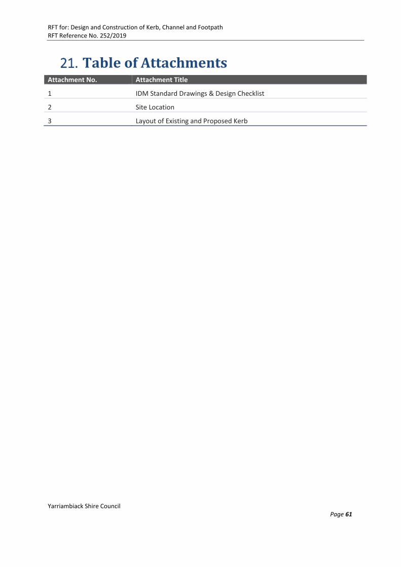
RFT for: Design and Construction of Kerb, Channel and Footpath RFT Reference No. 252/2019
Yarriambiack Shire Council Page 61
21. Table of Attachments Attachment No. Attachment Title
1 IDM Standard Drawings & Design Checklist
2 Site Location
3 Layout of Existing and Proposed Kerb
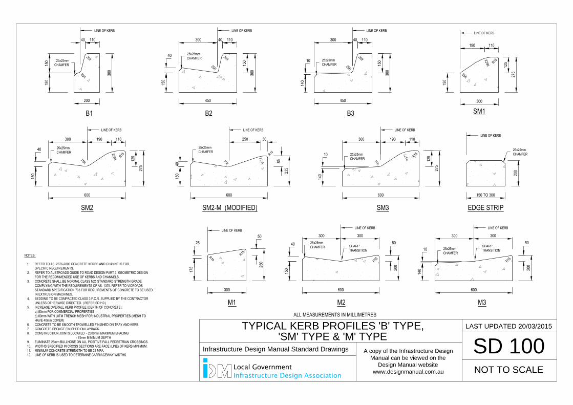
300
200
150
150
40 110
B1
300 40 110
150
300
450
150
40
300 40 110
450
SM1
190 110
125
275
300
R15
SM2
600
275
125
300 190 110
SM2-M (MODIFIED)
600
235
85
50250
SM3
600
275
125
300 190 110
M1
300
175 25
0
5025
M2
300 300
150
40
600
50
200
M3
300 300
600
50
200
EDGE STRIP
150 TO 300
25R
25R
B2 B3
25R
25R
25R
25R
140
10
150
300
225R
150
25R
150
40R15225R
R15
R15
R15 R15
75R
150
40
R15
140
10
R10
140
10
200
SD 100
NOT TO SCALE
LAST UPDATED 20/03/2015
TYPICAL KERB PROFILES 'B' TYPE,
'SM' TYPE & 'M' TYPE
NOTES:
1. REFER TO AS. 2876-2000 CONCRETE KERBS AND CHANNELS FORSPECIFIC REQUIREMENTS.
2. REFER TO AUSTROADS GUIDE TO ROAD DESIGN PART 3: GEOMETRIC DESIGNFOR THE RECOMMENDED USE OF KERBS AND CHANNELS.
3. CONCRETE SHALL BE NORMAL CLASS N25 STANDARD STRENGTH GRADECOMPLYING WITH THE REQUIREMENTS OF AS. 1379. REFER TO VICROADSSTANDARD SPECIFICATION 703 FOR REQUIREMENTS OF CONCRETE TO BE USEDIN EXTRUSION MACHINES.
4. BEDDING TO BE COMPACTED CLASS 3 F.C.R. SUPPLIED BY THE CONTRACTORUNLESS OTHERWISE DIRECTED. ( REFER SD110 )
5. INCREASE OVERALL KERB PROFILE (DEPTH OF CONCRETE):a) 80mm FOR COMMERCIAL PROPERTIESb) 80mm WITH L8TM TRENCH MESH FOR INDUSTRIAL PROPERTIES (MESH TOHAVE 40mm COVER)
6. CONCRETE TO BE SMOOTH TROWELLED FINISHED ON TRAY AND KERB.7. CONCRETE SPONGE FINISHED ON LAYBACK.8. CONSTRUCTION JOINTS LOCATED - 2500mm MAXIMUM SPACING
- 75mm MINIMUM DEPTH9. ELIMINATE 25mm BULLNOSE ON ALL POSITIVE FALL PEDESTRIAN CROSSINGS.10. WIDTHS SPECIFIED IN CROSS SECTIONS ARE FACE (LINE) OF KERB MINIMUM.11. MINIMUM CONCRETE STRENGTH TO BE 25 MPA.12. LINE OF KERB IS USED TO DETERMINE CARRIAGEWAY WIDTHS.
25x25mmCHAMFER
SHARPTRANSITION
SHARPTRANSITION
25x25mmCHAMFER
25x25mmCHAMFER
25x25mmCHAMFER
25x25mmCHAMFER 25x25mm
CHAMFER
25x25mmCHAMFER
25x25mmCHAMFER
LINE OF KERB
25x25mmCHAMFER
LINE OF KERBLINE OF KERB
LINE OF KERB LINE OF KERB LINE OF KERBLINE OF KERB
LINE OF KERBLINE OF KERBLINE OF KERBLINE OF KERB
SD 100
NOT TO SCALE
LAST UPDATED 20/03/2015
TYPICAL KERB PROFILES 'B' TYPE,
'SM' TYPE & 'M' TYPE
ALL MEASUREMENTS IN MILLIMETRES
Infrastructure Design Manual Standard Drawings
A copy of the Infrastructure Design
Manual can be viewed on the
Design Manual website
www.designmanual.com.au
Local GovernmentInfrastructure Design Association
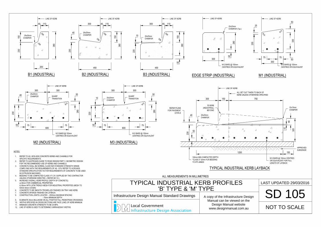
380
200
230
150
40 110
B1 (INDUSTRIAL)
300 40 110
150
380
45023
0
40
300 40 110
450
300
255 33
0
5025
300 300
230
40
600
50
280
300 300
600
50
280
300
25R
25R
B2 (INDUSTRIAL) B3 (INDUSTRIAL)
25R
25R
25R
25R
220
10
150
380
R15
R15 R15
R10
220
10
280
SD 105
NOT TO SCALE
LAST UPDATED 29/03/2016
TYPICAL INDUSTRIAL KERB PROFILES
'B' TYPE & 'M' TYPE
NOTES:
1. REFER TO AS. 2876-2000 CONCRETE KERBS AND CHANNELS FORSPECIFIC REQUIREMENTS.
2. REFER TO AUSTROADS GUIDE TO ROAD DESIGN PART 3: GEOMETRIC DESIGNFOR THE RECOMMENDED USE OF KERBS AND CHANNELS.
3. CONCRETE SHALL BE NORMAL CLASS N25 STANDARD STRENGTH GRADECOMPLYING WITH THE REQUIREMENTS OF AS. 1379. REFER TO VICROADSSTANDARD SPECIFICATION 703 FOR REQUIREMENTS OF CONCRETE TO BE USEDIN EXTRUSION MACHINES.
4. BEDDING TO BE COMPACTED CLASS 3 F.C.R. SUPPLIED BY THE CONTRACTORUNLESS OTHERWISE DIRECTED. ( REFER SD110 )
5. INCREASE OVERALL KERB PROFILE (DEPTH OF CONCRETE):a) 80mm FOR COMMERCIAL PROPERTIESb) 80mm WITH L8TM TRENCH MESH FOR INDUSTRIAL PROPERTIES (MESH TOHAVE 40mm COVER)
6. CONCRETE TO BE SMOOTH TROWELLED FINISHED ON TRAY AND KERB.7. CONCRETE SPONGE FINISHED ON LAYBACK.8. CONSTRUCTION JOINTS LOCATED - 2500mm MAXIMUM SPACING
- 75mm MINIMUM DEPTH9. ELIMINATE 25mm BULLNOSE ON ALL POSITIVE FALL PEDESTRIAN CROSSINGS.10. WIDTHS SPECIFIED IN CROSS SECTIONS ARE FACE (LINE) OF KERB MINIMUM.11. MINIMUM CONCRETE STRENGTH TO BE 25 MPA.12. LINE OF KERB IS USED TO DETERMINE CARRIAGEWAY WIDTHS.
EDGE STRIP (INDUSTRIAL) M1 (INDUSTRIAL)
M2 (INDUSTRIAL) M3 (INDUSTRIAL)
1200 150
90
320
300 150 750
230
40
10
TYPICAL INDUSTRIAL KERB LAYBACK
50
50 75 75 75 75
75 7550
50
50
50
100mm MIN COMPACTED DEPTH"CLASS 3" 20mm FCR BEDDINGTO 97% MMDD
N12 BARS @ 150mm CENTRESOR EQUIVALENT FOR FULLLENGTH OF LAYBACK
APPROVEDSUBGRADE
SHARPTRANSITION
25x25mmCHAMFER
25x25mmCHAMFER 25x25mm
CHAMFER
25x25mmCHAMFER 25x25mm
CHAMFER
25x25mmCHAMFER (Typ.)
15x15mmCHAMFER
25x25mmCHAMFER
LINE OF KERBLINE OF KERBLINE OF KERBLINE OF KERBLINE OF KERB
LINE OF KERB LINE OF KERBLINE OF KERB
SHARPTRANSITION
ALL SET OUT TAKEN TO BACK OFKERB UNLESS OTHERWISE SPECIFIED
'B' KERB(INDUSTRIAL)
BEYONDREFER PLANS
FOR PAVEMENTLEVELS
N12 BARS @ 150mmCENTRES OR EQUIVALENT
N12 BARS @ 150mmCENTRES OR EQUIVALENT
N12 BARS @ 150mmCENTRES OR EQUIVALENT
N12 BARS @ 150mmCENTRES OR EQUIVALENT
SD 105
NOT TO SCALE
LAST UPDATED 29/03/2016
TYPICAL INDUSTRIAL KERB PROFILES
'B' TYPE & 'M' TYPE
ALL MEASUREMENTS IN MILLIMETRES
Infrastructure Design Manual Standard Drawings
A copy of the Infrastructure Design
Manual can be viewed on the
Design Manual website
www.designmanual.com.au
Local GovernmentInfrastructure Design Association
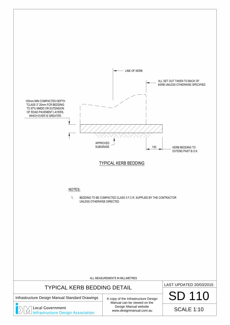
TYPICAL KERB BEDDING DETAIL
SD 110
SCALE 1:10
LAST UPDATED 20/03/2015
TYPICAL KERB BEDDING
150
NOTES:
1. BEDDING TO BE COMPACTED CLASS 3 F.C.R. SUPPLIED BY THE CONTRACTORUNLESS OTHERWISE DIRECTED
KERB BEDDING TOEXTEND PAST B.O.K.
100mm MIN COMPACTED DEPTH"CLASS 3" 20mm FCR BEDDINGTO 97% MMDD OR EXTENSIONOF ROAD PAVEMENT LAYERS,
WHICH EVER IS GREATER.
APPROVEDSUBGRADE
LINE OF KERB
ALL SET OUT TAKEN TO BACK OFKERB UNLESS OTHERWISE SPECIFIED
ALL MEASUREMENTS IN MILLIMETRES
Infrastructure Design Manual Standard Drawings
A copy of the Infrastructure Design
Manual can be viewed on the
Design Manual website
www.designmanual.com.au
Local GovernmentInfrastructure Design Association
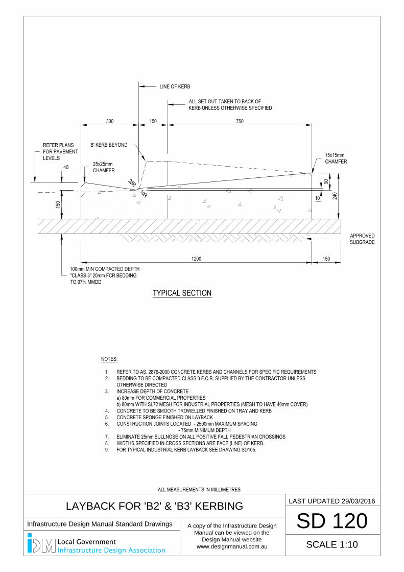
LAYBACK FOR 'B2' & 'B3' KERBING
SD 120
TYPICAL SECTION
1200 150
9024
0
SCALE 1:10
LAST UPDATED 29/03/2016
300 150 750
25R10R
150
40
NOTES:
1. REFER TO AS. 2876-2000 CONCRETE KERBS AND CHANNELS FOR SPECIFIC REQUIREMENTS2. BEDDING TO BE COMPACTED CLASS 3 F.C.R. SUPPLIED BY THE CONTRACTOR UNLESS
OTHERWISE DIRECTED3. INCREASE DEPTH OF CONCRETE
a) 80mm FOR COMMERCIAL PROPERTIESb) 80mm WITH SL72 MESH FOR INDUSTRIAL PROPERTIES (MESH TO HAVE 40mm COVER)
4. CONCRETE TO BE SMOOTH TROWELLED FINISHED ON TRAY AND KERB5. CONCRETE SPONGE FINISHED ON LAYBACK6. CONSTRUCTION JOINTS LOCATED - 2500mm MAXIMUM SPACING
- 75mm MINIMUM DEPTH7. ELIMINATE 25mm BULLNOSE ON ALL POSITIVE FALL PEDESTRIAN CROSSINGS8. WIDTHS SPECIFIED IN CROSS SECTIONS ARE FACE (LINE) OF KERB.9. FOR TYPICAL INDUSTRIAL KERB LAYBACK SEE DRAWING SD105.
10
LINE OF KERB
ALL SET OUT TAKEN TO BACK OFKERB UNLESS OTHERWISE SPECIFIED
100mm MIN COMPACTED DEPTH"CLASS 3" 20mm FCR BEDDINGTO 97% MMDD
25x25mmCHAMFER
15x15mmCHAMFER
REFER PLANSFOR PAVEMENTLEVELS
APPROVEDSUBGRADE
'B' KERB BEYOND
ALL MEASUREMENTS IN MILLIMETRES
Infrastructure Design Manual Standard Drawings
A copy of the Infrastructure Design
Manual can be viewed on the
Design Manual website
www.designmanual.com.au
Local GovernmentInfrastructure Design Association

SD 130
KERB & CHANNEL INSTALLATION ABUTTING
EXISTING PAVEMENT
600 MIN
TYPICAL SECTIONSA
WCU
T LIN
E
SCALE 1:10
LAST UPDATED 29/03/2016
NOTES:
1. REFER TO CONCRETE AS. 2876-2000 CONCRETE KERBS AND CHANNELS2. BEDDING TO BE COMPACTED CLASS 3 F.C.R. SUPPLIED BY THE CONTRACTOR UNLESS
OTHERWISE DIRECTED3. CONCRETE TO BE SMOOTH TROWELLED FINISHED ON TRAY AND KERB4. CONSTRUCTION JOINTS LOCATED - 2500mm MAXIMUM SPACING
- 75mm MINIMUM DEPTH5. ELIMINATE 25mm BULLNOSE ON ALL POSITIVE FALL PEDESTRIAN CROSSINGS6. WIDTHS SPECIFIED IN CROSS SECTIONS ARE FACE (LINE) OF KERB.
300 MIN
KEY
FOR
ASPH
ALT
30mm COMPACTED DEPTH TYPE N10mm NOM. SIZE ASPHALT U.N.O.
NEW PAVEMENT COMPRISING OF:CLASS 2 FCR COMPACTED TO MIN 98%,DEPTH TO BE MIN 250mm OR MATCHTO EXISTING PAVEMENT
LINE OF KERB
NEW KERB PROFILEMATCH EXISTINGINVERTS.
MINIMUM SEAL OVERLAP
EXISTING SUBGRADE
100mm MIN COMPACTED DEPTH"CLASS 3" 20mm FCR BEDDINGTO 97% MMDD OR EXTENSIONOF ROAD PAVEMENT LAYERS,
WHICH EVER IS GREATER.
EXISTINGPAVEMENT
ALL MEASUREMENTS IN MILLIMETRES
Infrastructure Design Manual Standard Drawings
A copy of the Infrastructure Design
Manual can be viewed on the
Design Manual website
www.designmanual.com.au
Local GovernmentInfrastructure Design Association
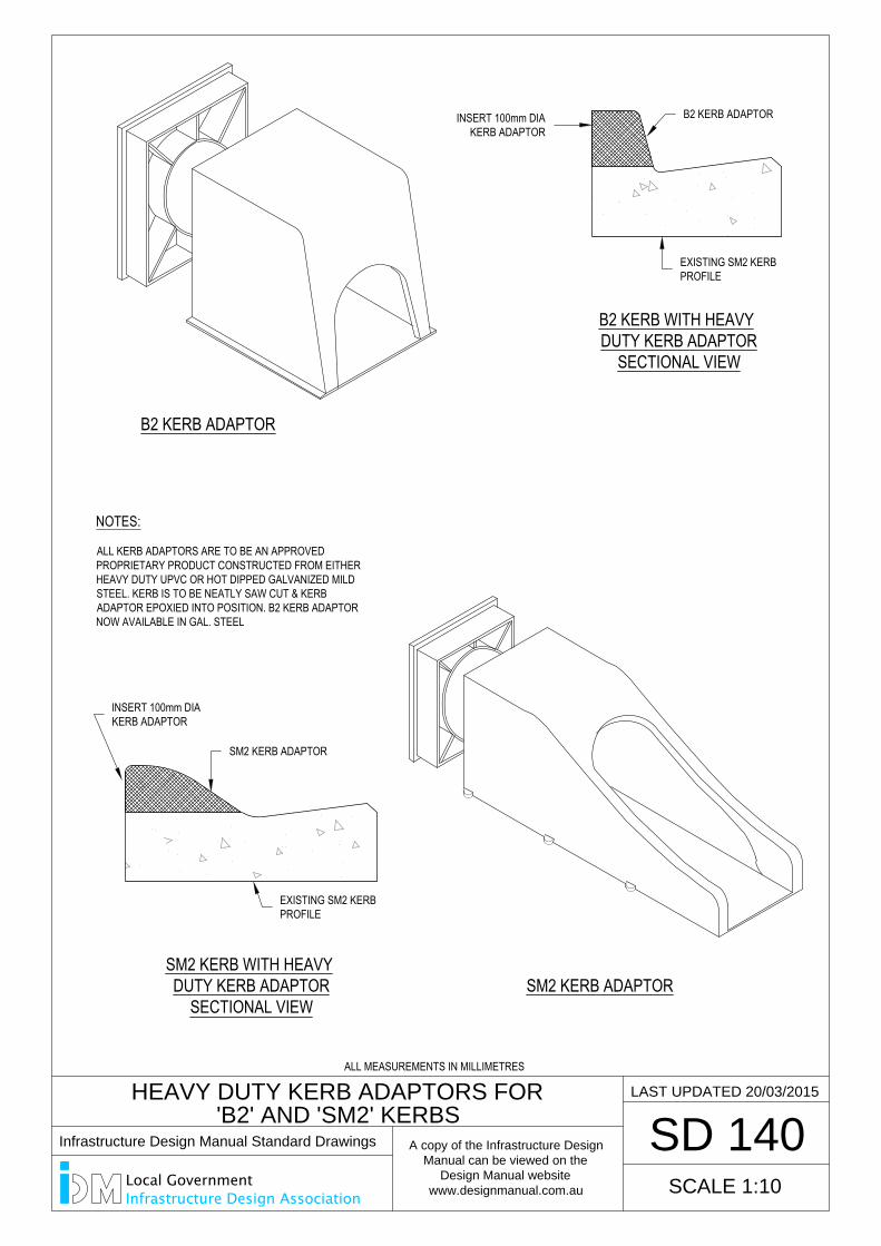
B2 KERB ADAPTOR
B2 KERB WITH HEAVYDUTY KERB ADAPTOR
SECTIONAL VIEW
SM2 KERB ADAPTOR
SD 140
SCALE 1:10
LAST UPDATED 20/03/2015
HEAVY DUTY KERB ADAPTORS FOR
'B2' AND 'SM2' KERBS
SM2 KERB WITH HEAVYDUTY KERB ADAPTOR
SECTIONAL VIEW
NOTES:
ALL KERB ADAPTORS ARE TO BE AN APPROVEDPROPRIETARY PRODUCT CONSTRUCTED FROM EITHERHEAVY DUTY UPVC OR HOT DIPPED GALVANIZED MILDSTEEL. KERB IS TO BE NEATLY SAW CUT & KERBADAPTOR EPOXIED INTO POSITION. B2 KERB ADAPTORNOW AVAILABLE IN GAL. STEEL
SM2 KERB ADAPTOR
EXISTING SM2 KERBPROFILE
INSERT 100mm DIAKERB ADAPTOR
EXISTING SM2 KERBPROFILE
B2 KERB ADAPTORINSERT 100mm DIAKERB ADAPTOR
ALL MEASUREMENTS IN MILLIMETRES
Infrastructure Design Manual Standard Drawings
A copy of the Infrastructure Design
Manual can be viewed on the
Design Manual website
www.designmanual.com.au
Local GovernmentInfrastructure Design Association
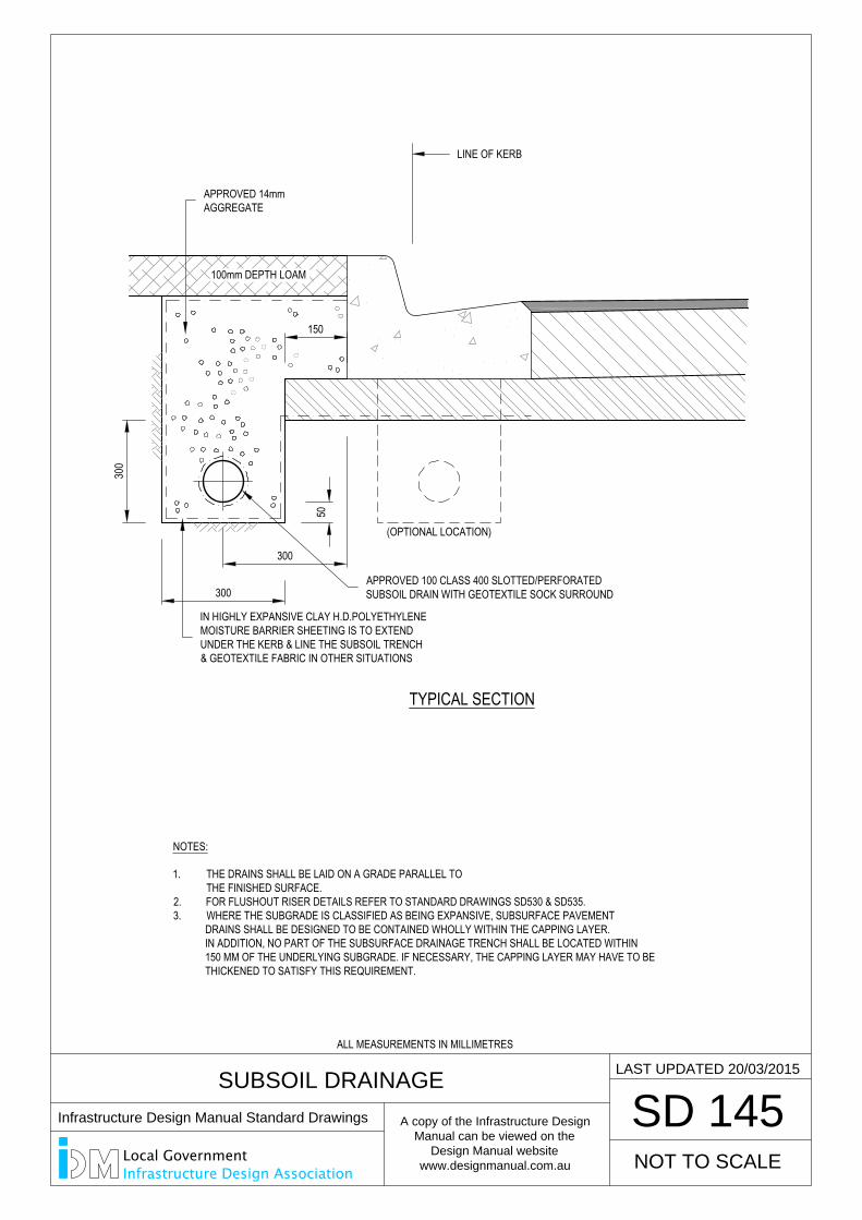
SUBSOIL DRAINAGE
SD 145
100mm DEPTH LOAM
50
TYPICAL SECTION
NOTES:
1. THE DRAINS SHALL BE LAID ON A GRADE PARALLEL TO THE FINISHED SURFACE.2. FOR FLUSHOUT RISER DETAILS REFER TO STANDARD DRAWINGS SD530 & SD535.3. WHERE THE SUBGRADE IS CLASSIFIED AS BEING EXPANSIVE, SUBSURFACE PAVEMENT DRAINS SHALL BE DESIGNED TO BE CONTAINED WHOLLY WITHIN THE CAPPING LAYER. IN ADDITION, NO PART OF THE SUBSURFACE DRAINAGE TRENCH SHALL BE LOCATED WITHIN 150 MM OF THE UNDERLYING SUBGRADE. IF NECESSARY, THE CAPPING LAYER MAY HAVE TO BE THICKENED TO SATISFY THIS REQUIREMENT.
300
300
(OPTIONAL LOCATION)
NOT TO SCALE
LAST UPDATED 20/03/2015
300
150
LINE OF KERB
APPROVED 14mmAGGREGATE
APPROVED 100 CLASS 400 SLOTTED/PERFORATEDSUBSOIL DRAIN WITH GEOTEXTILE SOCK SURROUND
IN HIGHLY EXPANSIVE CLAY H.D.POLYETHYLENEMOISTURE BARRIER SHEETING IS TO EXTENDUNDER THE KERB & LINE THE SUBSOIL TRENCH& GEOTEXTILE FABRIC IN OTHER SITUATIONS
ALL MEASUREMENTS IN MILLIMETRES
Infrastructure Design Manual Standard Drawings
A copy of the Infrastructure Design
Manual can be viewed on the
Design Manual website
www.designmanual.com.au
Local GovernmentInfrastructure Design Association
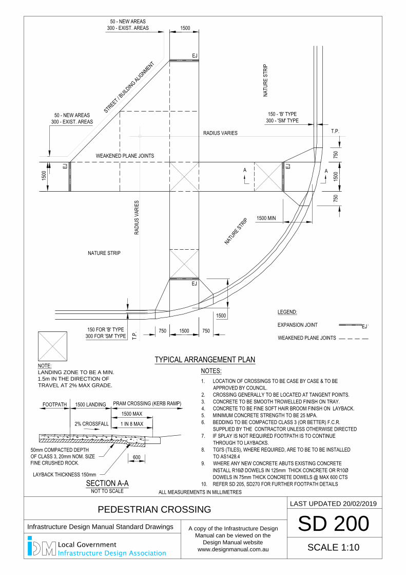
1500
50 - NEW AREAS300 - EXIST. AREAS
SD 200
PEDESTRIAN CROSSING
T.P.
WEAKENED PLANE JOINTS
STREET / BUILD
ING ALIGNMENT
NATU
RE S
TRIP
NATURE STR
IPNATURE STRIP
RADIUS VARIES T.P.
EJ
EJEJ EJ
150050 - NEW AREAS
300 - EXIST. AREAS
1500 MIN
750
750
1500
NOTES:
LEGEND:
EXPANSION JOINT
WEAKENED PLANE JOINTS
EJ
1500
7501500750150 FOR 'B' TYPE300 FOR 'SM' TYPE
150 - 'B' TYPE300 - 'SM' TYPE
TYPICAL ARRANGEMENT PLAN
SCALE 1:10
LAST UPDATED 20/02/2019
RADI
US V
ARIE
S
SECTION A-ANOT TO SCALE
1500 MAX
A A
600
1. LOCATION OF CROSSINGS TO BE CASE BY CASE & TO BEAPPROVED BY COUNCIL.
2. CROSSING GENERALLY TO BE LOCATED AT TANGENT POINTS.3. CONCRETE TO BE SMOOTH TROWELLED FINISH ON TRAY.4. CONCRETE TO BE FINE SOFT HAIR BROOM FINISH ON LAYBACK.5. MINIMUM CONCRETE STRENGTH TO BE 25 MPA.6. BEDDING TO BE COMPACTED CLASS 3 (OR BETTER) F.C.R.
SUPPLIED BY THE CONTRACTOR UNLESS OTHERWISE DIRECTED7. IF SPLAY IS NOT REQUIRED FOOTPATH IS TO CONTINUE
THROUGH TO LAYBACKS.8. TGI'S (TILES), WHERE REQUIRED, ARE TO BE TO BE INSTALLED
TO AS1428.49. WHERE ANY NEW CONCRETE ABUTS EXISTING CONCRETE
INSTALL R16Ø DOWELS IN 125mm THICK CONCRETE OR R10ØDOWELS IN 75mm THICK CONCRETE DOWELS @ MAX 600 CTS
10. REFER SD 205, SD270 FOR FURTHER FOOTPATH DETAILS
50mm COMPACTED DEPTHOF CLASS 3, 20mm NOM. SIZEFINE CRUSHED ROCK.
LAYBACK THICKNESS 150mm
FOOTPATH PRAM CROSSING (KERB RAMP)
1 IN 8 MAX
NOTE:LANDING ZONE TO BE A MIN.
1.5m IN THE DIRECTION OF
TRAVEL AT 2% MAX GRADE.
1500 LANDING
2% CROSSFALL
ALL MEASUREMENTS IN MILLIMETRES
Infrastructure Design Manual Standard Drawings
A copy of the Infrastructure Design
Manual can be viewed on the
Design Manual website
www.designmanual.com.au
Local GovernmentInfrastructure Design Association
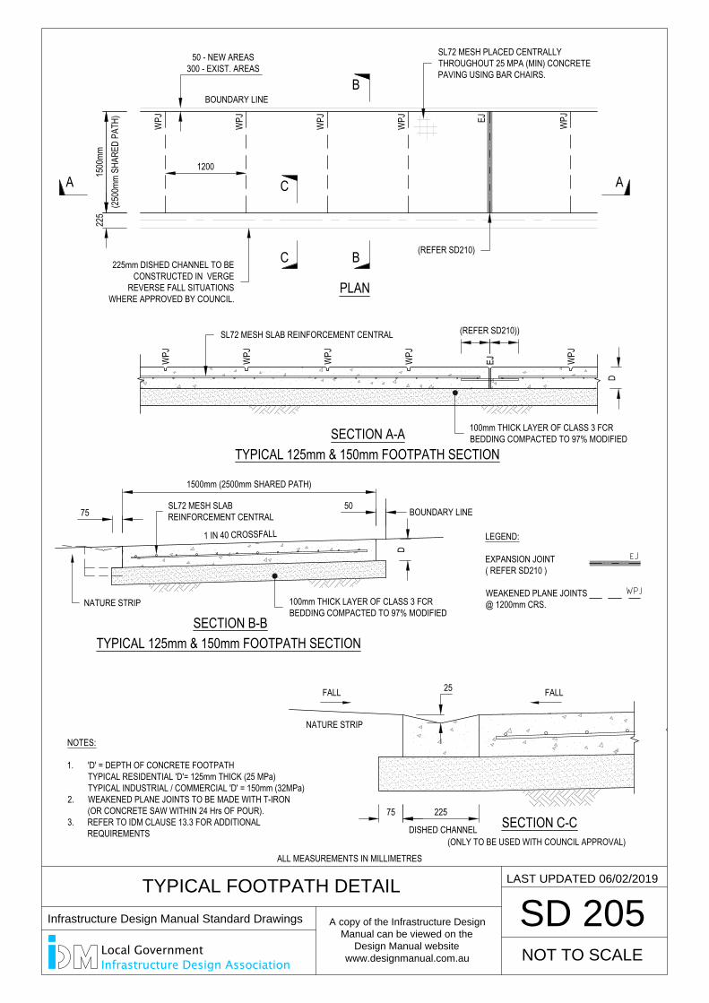
SECTION B-B
SL72 MESH SLABREINFORCEMENT CENTRAL
TYPICAL FOOTPATH DETAIL
SD 205
NOT TO SCALE
LAST UPDATED 06/02/2019
LEGEND:
EXPANSION JOINT( REFER SD210 )
WEAKENED PLANE JOINTS@ 1200mm CRS.
TYPICAL 125mm & 150mm FOOTPATH SECTION
PLAN
B
B
50 - NEW AREAS300 - EXIST. AREAS
BOUNDARY LINE
1200W
PJ
WPJ
WPJ
WPJ EJ WPJ
NOTES:
1. 'D' = DEPTH OF CONCRETE FOOTPATHTYPICAL RESIDENTIAL 'D'= 125mm THICK (25 MPa)TYPICAL INDUSTRIAL / COMMERCIAL 'D' = 150mm (32MPa)
2. WEAKENED PLANE JOINTS TO BE MADE WITH T-IRON(OR CONCRETE SAW WITHIN 24 Hrs OF POUR).
3. REFER TO IDM CLAUSE 13.3 FOR ADDITIONALREQUIREMENTS
225
C
C
DISHED CHANNEL
225
FALL FALL25
SECTION C-C(ONLY TO BE USED WITH COUNCIL APPROVAL)
1 IN 40 CROSSFALL
WPJ
EJ
D
A A
SECTION A-ATYPICAL 125mm & 150mm FOOTPATH SECTION
BOUNDARY LINE50
NATURE STRIP
75
75
NATURE STRIP
D
(250
0mm
SHAR
ED P
ATH)
1500mm (2500mm SHARED PATH)
WPJ
WPJ
WPJ
WPJ
SL72 MESH PLACED CENTRALLYTHROUGHOUT 25 MPA (MIN) CONCRETEPAVING USING BAR CHAIRS.
225mm DISHED CHANNEL TO BECONSTRUCTED IN VERGE
REVERSE FALL SITUATIONSWHERE APPROVED BY COUNCIL.
(REFER SD210)
1500
mm
SL72 MESH SLAB REINFORCEMENT CENTRAL
100mm THICK LAYER OF CLASS 3 FCRBEDDING COMPACTED TO 97% MODIFIED
(REFER SD210))
100mm THICK LAYER OF CLASS 3 FCRBEDDING COMPACTED TO 97% MODIFIED
ALL MEASUREMENTS IN MILLIMETRES
Infrastructure Design Manual Standard Drawings
A copy of the Infrastructure Design
Manual can be viewed on the
Design Manual website
www.designmanual.com.au
Local GovernmentInfrastructure Design Association
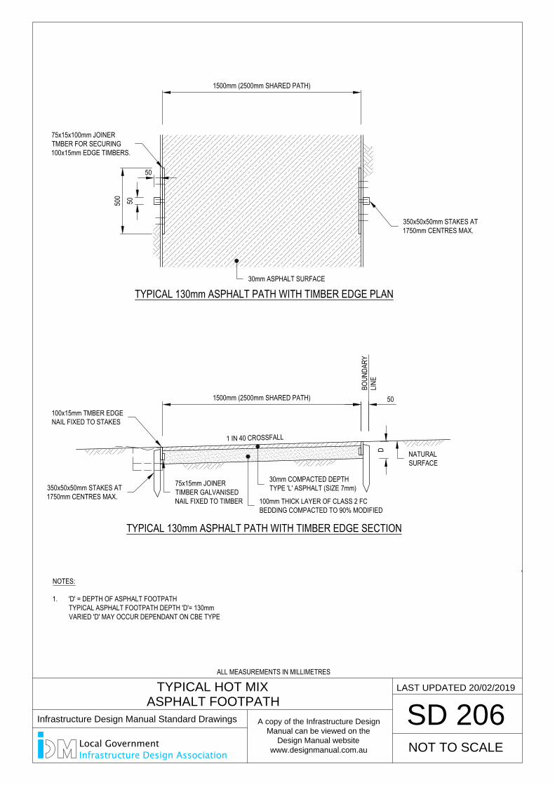
TYPICAL HOT MIX
ASPHALT FOOTPATH
SD 206
NOT TO SCALE
LAST UPDATED 20/02/2019
TYPICAL 130mm ASPHALT PATH WITH TIMBER EDGE SECTION
NOTES:
1. 'D' = DEPTH OF ASPHALT FOOTPATHTYPICAL ASPHALT FOOTPATH DEPTH 'D'= 130mmVARIED 'D' MAY OCCUR DEPENDANT ON CBE TYPE
1 IN 40 CROSSFALL
D
1500mm (2500mm SHARED PATH)
100mm THICK LAYER OF CLASS 2 FCBEDDING COMPACTED TO 90% MODIFIED
30mm COMPACTED DEPTHTYPE 'L' ASPHALT (SIZE 7mm)
NATURALSURFACE
50
BOUN
DARY
LINE
350x50x50mm STAKES AT1750mm CENTRES MAX.
100x15mm TMBER EDGENAIL FIXED TO STAKES
75x15mm JOINERTIMBER GALVANISEDNAIL FIXED TO TIMBER
500
1500mm (2500mm SHARED PATH)
30mm ASPHALT SURFACE
75x15x100mm JOINERTMBER FOR SECURING100x15mm EDGE TIMBERS.
50
50
350x50x50mm STAKES AT1750mm CENTRES MAX.
TYPICAL 130mm ASPHALT PATH WITH TIMBER EDGE PLAN
ALL MEASUREMENTS IN MILLIMETRES
Infrastructure Design Manual Standard Drawings
A copy of the Infrastructure Design
Manual can be viewed on the
Design Manual website
www.designmanual.com.au
Local GovernmentInfrastructure Design Association
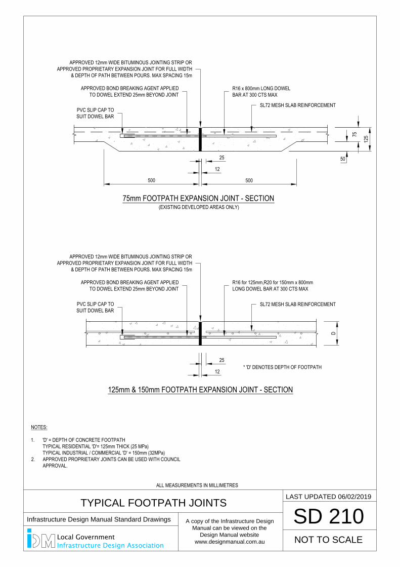
TYPICAL FOOTPATH JOINTS
SD 210
75mm FOOTPATH EXPANSION JOINT - SECTION
125
50
75
500 500
25
12
125mm & 150mm FOOTPATH EXPANSION JOINT - SECTION
25
12
D
(EXISTING DEVELOPED AREAS ONLY)
NOT TO SCALE
LAST UPDATED 06/02/2019
* 'D' DENOTES DEPTH OF FOOTPATH
NOTES:
1. 'D' = DEPTH OF CONCRETE FOOTPATHTYPICAL RESIDENTIAL 'D'= 125mm THICK (25 MPa)TYPICAL INDUSTRIAL / COMMERCIAL 'D' = 150mm (32MPa)
2. APPROVED PROPRIETARY JOINTS CAN BE USED WITH COUNCILAPPROVAL.
R16 x 800mm LONG DOWELBAR AT 300 CTS MAX
APPROVED 12mm WIDE BITUMINOUS JOINTING STRIP ORAPPROVED PROPRIETARY EXPANSION JOINT FOR FULL WIDTH
& DEPTH OF PATH BETWEEN POURS. MAX SPACING 15m
SL72 MESH SLAB REINFORCEMENT
R16 for 125mm,R20 for 150mm x 800mmLONG DOWEL BAR AT 300 CTS MAX
SL72 MESH SLAB REINFORCEMENT
APPROVED BOND BREAKING AGENT APPLIEDTO DOWEL EXTEND 25mm BEYOND JOINT
PVC SLIP CAP TOSUIT DOWEL BAR
APPROVED 12mm WIDE BITUMINOUS JOINTING STRIP ORAPPROVED PROPRIETARY EXPANSION JOINT FOR FULL WIDTH
& DEPTH OF PATH BETWEEN POURS. MAX SPACING 15m
APPROVED BOND BREAKING AGENT APPLIEDTO DOWEL EXTEND 25mm BEYOND JOINT
PVC SLIP CAP TOSUIT DOWEL BAR
ALL MEASUREMENTS IN MILLIMETRES
Infrastructure Design Manual Standard Drawings
A copy of the Infrastructure Design
Manual can be viewed on the
Design Manual website
www.designmanual.com.au
Local GovernmentInfrastructure Design Association
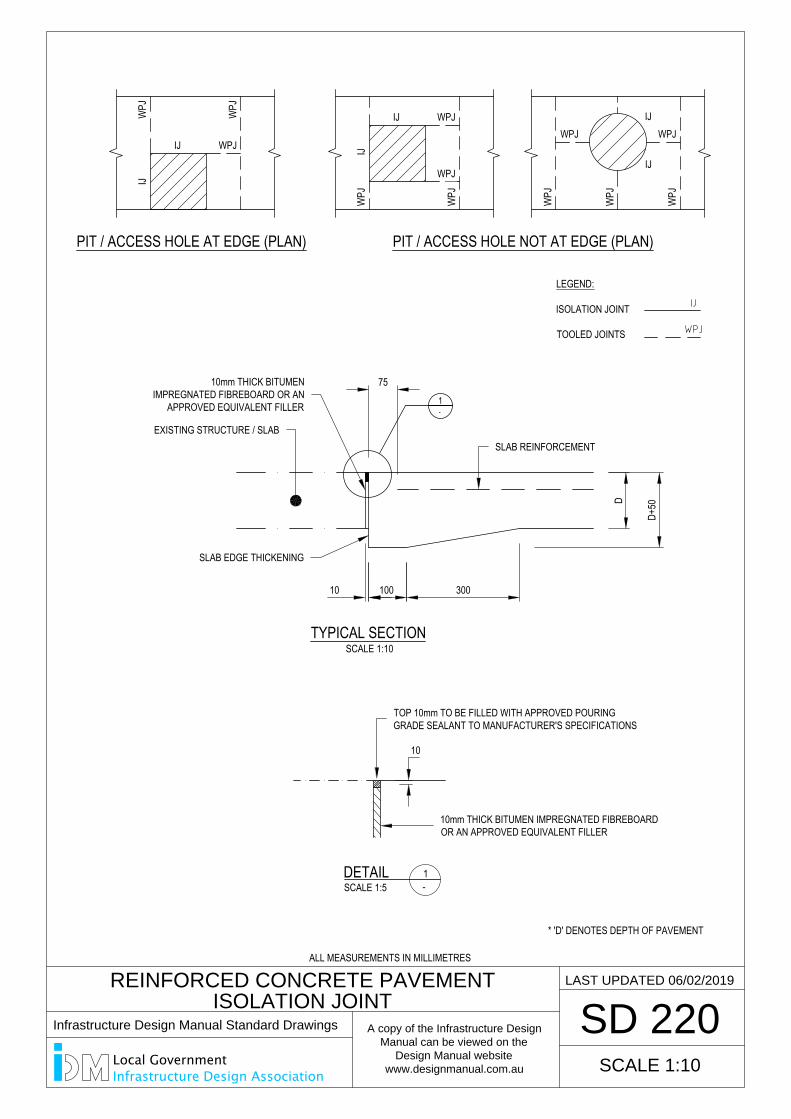
TYPICAL SECTIONSCALE 1:10
10010
75
10
D+50
300
D
DETAIL
1-
REINFORCED CONCRETE PAVEMENT
ISOLATION JOINT
SD 220
SCALE 1:10
LAST UPDATED 06/02/2019
1-SCALE 1:5
* 'D' DENOTES DEPTH OF PAVEMENT
PIT / ACCESS HOLE AT EDGE (PLAN)W
PJ
IJIJ
WPJ
WPJ
PIT / ACCESS HOLE NOT AT EDGE (PLAN)
IJ
IJ WPJ
WPJ
WPJ
WPJ
LEGEND:
ISOLATION JOINT
TOOLED JOINTS
IJ
IJ
WPJ
WPJ
WPJ
WPJ
WPJ
10mm THICK BITUMENIMPREGNATED FIBREBOARD OR AN
APPROVED EQUIVALENT FILLER
SLAB EDGE THICKENING
EXISTING STRUCTURE / SLABSLAB REINFORCEMENT
TOP 10mm TO BE FILLED WITH APPROVED POURINGGRADE SEALANT TO MANUFACTURER'S SPECIFICATIONS
10mm THICK BITUMEN IMPREGNATED FIBREBOARDOR AN APPROVED EQUIVALENT FILLER
ALL MEASUREMENTS IN MILLIMETRES
Infrastructure Design Manual Standard Drawings
A copy of the Infrastructure Design
Manual can be viewed on the
Design Manual website
www.designmanual.com.au
Local GovernmentInfrastructure Design Association
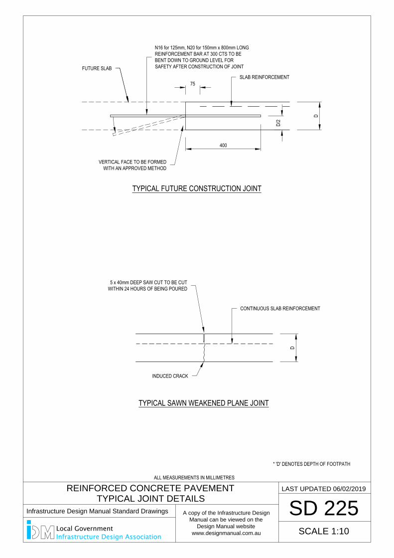
TYPICAL FUTURE CONSTRUCTION JOINT
75
400
D/2
D
REINFORCED CONCRETE PAVEMENT
TYPICAL JOINT DETAILS
SD 225
SCALE 1:10
LAST UPDATED 06/02/2019
TYPICAL SAWN WEAKENED PLANE JOINT
D
* 'D' DENOTES DEPTH OF FOOTPATH
5 x 40mm DEEP SAW CUT TO BE CUTWITHIN 24 HOURS OF BEING POURED
INDUCED CRACK
VERTICAL FACE TO BE FORMEDWITH AN APPROVED METHOD
CONTINUOUS SLAB REINFORCEMENT
SLAB REINFORCEMENT
N16 for 125mm, N20 for 150mm x 800mm LONGREINFORCEMENT BAR AT 300 CTS TO BEBENT DOWN TO GROUND LEVEL FORSAFETY AFTER CONSTRUCTION OF JOINTFUTURE SLAB
ALL MEASUREMENTS IN MILLIMETRES
Infrastructure Design Manual Standard Drawings
A copy of the Infrastructure Design
Manual can be viewed on the
Design Manual website
www.designmanual.com.au
Local GovernmentInfrastructure Design Association
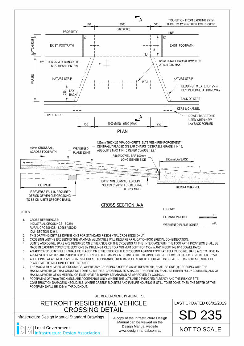
PLAN
3000
VARI
ES
750
750 4000 (MIN) - 6600 (MAX) 750
500
RETROFIT RESIDENTIAL VEHICLE
CROSSING DETAIL
SD 235
PROPERTY LINE
EXIST. FOOTPATH
(Max 6600)
KERB & CHANNEL
WPJ
TJ
EJ EJNATURE STRIP
LEGEND:
EXPANSION JOINT
WEAKENED PLANE JOINTS
NOTES:
1. CROSS REFERENCES:INDUSTRIAL CROSSINGS - SD250RURAL CROSSINGS - SD255 / SD260IDM - SECTION 12.9.1.
2. THIS DRAWING DETAILS DIMENSIONS FOR STANDARD RESIDENTIAL CROSSINGS ONLY.3. CROSSING WIDTHS EXCEEDING THE MAXIMUM ALLOWABLE WILL REQUIRE APPLICATION FOR SPECIAL CONSIDERATION.4. JOINTS AND DOWEL BARS ARE REQUIRED ON EITHER SIDE OF THE CROSSING AT THE INTERFACE WITH THE FOOTPATH. PROVISION SHALL BE
MADE IN EXISTING CONCRETE SECTIONS BY DRILLING HOLES TO A MINIMUM DEPTH OF 150mm AND INSERTING R10 DOWEL BARS.5. AN APPROVED JOINT FILLER SHALL BE PLACED ON EITHER SIDE OF THE CROSSING AGAINST FOOTPATH SLABS. DOWEL BARS ARE TO HAVE AN
APPROVED BOND BREAKER APPLIED TO THE END OF THE BAR INSERTED INTO THE EXISTING CONCRETE FOOTPATH SECTIONS REFER SD220.6. ADDITIONAL WEAKENED PLANE JOINTS REQUIRED IF DISTANCE FROM BACK OF KERB TO FOOTPATH IS GREATER THAN 3000 AND SHALL BE
PLACED AT THE MIDPOINT OF THE DISTANCE.7. THE MAXIMUM NUMBER OF CROSSINGS, WHERE ANY CROSSING EXCEEDS 3.5 METRES WIDTH, SHALL BE ONE (1) CROSSING WITH THE
MAXIMUM WIDTH OF THAT CROSSING TO BE 6.0 METRES. CROSSINGS TO ADJACENT PROPERTIES SHALL BE EITHER FULLY COMBINED, AND OFMAXIMUM WIDTH OF 6.0 METRES, OR ELSE HAVE A MINIMUM SEPARATION AS APPROVED BY COUNCIL.
8. FOOTPATHS OF 75mm THICKNESS ARE ACCEPTABLE ONLY WHERE THE LOTS ARE DEVELOPED ALREADY AND THE RISK OF SITECONSTRUCTION DAMAGE IS NEGLIGIBLE. WHERE GREENFIELD SITES AND FUTURE HOUSING IS STILL TO BE DONE, THEN THE DEPTH OF THEFOOTPATH SHALL BE 125mm THROUGHOUT.
EXIST. FOOTPATH
MATC
H EX
IST
NOT TO SCALE
LAST UPDATED 06/02/2019
A
A
LAYBACK
CROSS SECTION A-A
FOOTPATH
40mm CROSSFALLACROSS FOOTPATH
KERB & CHANNEL
750mm LAYBACK
LIP OF KERB
BACK OF KERB
TRANSITION FROM EXISTING 75mmTHICK TO 125mm THICK OVER 500mm.
R16Ø DOWEL BARS 800mm LONGAT 600 CTS MAX
DOWEL BARS TO BEUSED WHEN NEWLAYBACK FORMED
125mm THICK 25 MPA CONCRETE, SL72 MESH REINFORCEMENTCENTRALLY PLACED ON BAR CHAIRS (DESIRABLE GRADE 1 IN 15,ABSOLUTE MAX 1 IN 10 REFER CLAUSE 12.9.1)WEAKENED
PLANE JOINT
IF REVERSE FALL IS REQUIREDDESIGN OF VEHICLE CROSSING
TO BE ON A SITE SPECIFIC BASIS.
100mm MIN COMPACTED DEPTH"CLASS 3" 20mm FCR BEDDING
TO 97% MMDD
R16Ø DOWEL BAR 800mmLONG EITHER SIDE
125 THICK 25 MPA CONCRETESL72 MESH CENTRAL
BEDDING TO EXTEND 125mmBEYOND EDGE OF DRIVEWAY
NATURE STRIP
500
ALL MEASUREMENTS IN MILLIMETRES
Infrastructure Design Manual Standard Drawings
A copy of the Infrastructure Design
Manual can be viewed on the
Design Manual website
www.designmanual.com.au
Local GovernmentInfrastructure Design Association
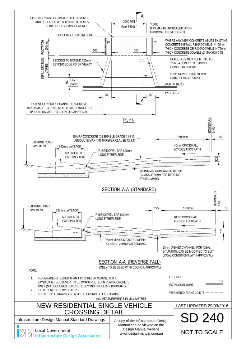
NEW RESIDENTIAL SINGLE VEHICLE
CROSSING DETAIL
SD 240
3000 MIN
1500
mm
750
FOOT
PATH
INFI
LL S
ECTI
ONVA
RIES
LAYBACK
WHERE ANY NEW CONCRETE ABUTS EXISTINGCONCRETE INSTALL R16Ø DOWELS IN 125mmTHICK CONCRETE OR R10Ø DOWELS IN 75mmTHICK CONCRETE DOWELS @ MAX 600 CTS
EXTENT OF KERB & CHANNEL TO REMOVEANY DAMAGE TO ROAD SEAL TO BE REINSTATED
BY CONTRACTOR TO COUNCILS APPROVAL
NOTE:
1. FOR GRADES STEEPER THAN 1 IN 15 REFER CLAUSE 12.9.1.LAYBACK & CROSSOVER, TO BE CONSTRUCTED IN PLAIN CONCRETE ONLY (NO COLOURED CONCRETE BEYOND PROPERTY BOUNDARY)
2. T.O.K. DENOTES TOP OF KERB3. FOR STEEP TERRAIN CONTACT THE COUNCIL FOR GUIDANCE.
PROPERTY / BUILDING LINE
LAST UPDATED 29/03/2016
LEGEND:
EXPANSION JOINT
WEAKENED PLANE JOINTS
EJ
A
A
NOT TO SCALE
(Max 6600) *
500
EJ
500
EJ750 750 LIP OF KERB
1500mm
125
SECTION A-A (REVERSE FALL)
225
40mm CROSSFALLACROSS FOOTPATH
(ONLY TO BE USED WITH COUNCIL APPROVAL)
1500mm
125
SECTION A-A (STANDARD)
40mm CROSSFALLACROSS FOOTPATH
750mm LAYBACK
750mm LAYBACK
BACK OF KERB
50
BOUN
DARY
LINE
50
BOUN
DARY
LINE
25mm DISHED CHANNEL (FOR IDEALSITUATION, CAN BE MODIFIED TO SUITLOCAL CONDITIONS WITH APPROVAL)
25 MPA CONCRETE (DESIRABLE GRADE 1 IN 15,ABSOLUTE MAX 1 IN 10 REFER CLAUSE 12.9.1)
100mm MIN COMPACTED DEPTH"CLASS 3" 20mm FCR BEDDINGTO 97% MMDD
75mm MIN COMPACTED DEPTH"CLASS 3" 20mm FCR BEDDING
PLACE SL72 MESH CENTRAL TO25 MPA CONCRETE PAVINGUSING BAR CHAIRS.
EXISTING ROADPAVEMENT
MATCH INTOEXISTING TOK
MATCH INTOEXISTING TOK
EXISTING ROADPAVEMENT
R16Ø DOWEL BARS 800mmLONG AT 600 CTS MAX
EXISTING 75mm FOOTPATH TO BE REMOVEDAND REPLACED WITH 125mm THICK SL72
REINFORCED 25 MPA CONCRETE *NOTETHIS MAY BE INCREASED UPONAPPROVAL FROM COUNCIL
BEDDING TO EXTEND 125mmBEYOND EDGE OF DRIVEWAY
R16Ø DOWEL BAR 800mmLONG EITHER SIDE
R16Ø DOWEL BAR 800mmLONG EITHER SIDE
ALL MEASUREMENTS IN MILLIMETRES
Infrastructure Design Manual Standard Drawings
A copy of the Infrastructure Design
Manual can be viewed on the
Design Manual website
www.designmanual.com.au
Local GovernmentInfrastructure Design Association
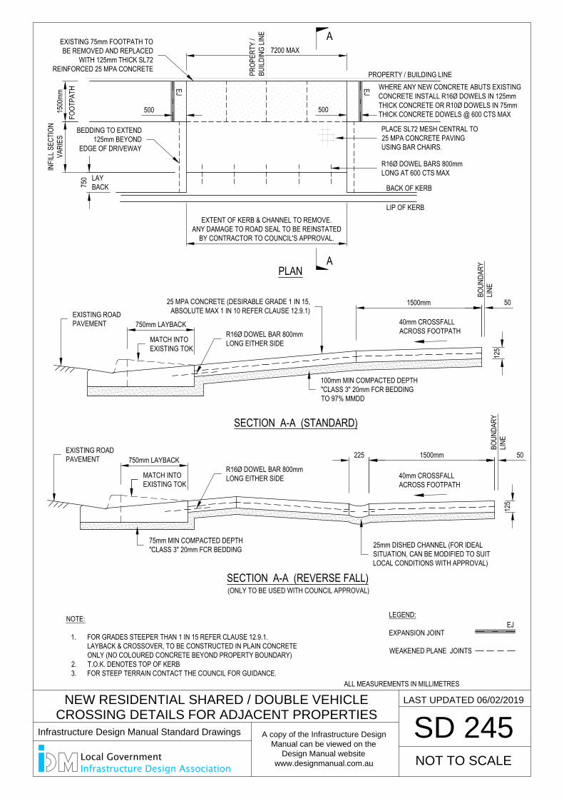
SD 245
LAST UPDATED 06/02/2019
NOT TO SCALE
7200 MAX
EXTENT OF KERB & CHANNEL TO REMOVE.ANY DAMAGE TO ROAD SEAL TO BE REINSTATED
BY CONTRACTOR TO COUNCIL'S APPROVAL.
WHERE ANY NEW CONCRETE ABUTS EXISTINGCONCRETE INSTALL R16Ø DOWELS IN 125mmTHICK CONCRETE OR R10Ø DOWELS IN 75mmTHICK CONCRETE DOWELS @ 600 CTS MAX
PLAN
A
A
1500
mmIN
FILL
SEC
TION
VARI
ESFO
OTPA
TH
LEGEND:
EXPANSION JOINT
WEAKENED PLANE JOINTS
EJ
NEW RESIDENTIAL SHARED / DOUBLE VEHICLE
CROSSING DETAILS FOR ADJACENT PROPERTIES
PROPERTY / BUILDING LINE
500
EJ
500
EJ
750 LAY
BACK
LIP OF KERB
1500mm
125
SECTION A-A (REVERSE FALL)
225
40mm CROSSFALLACROSS FOOTPATH
(ONLY TO BE USED WITH COUNCIL APPROVAL)
1500mm
125
SECTION A-A (STANDARD)
40mm CROSSFALLACROSS FOOTPATH
750mm LAYBACK
750mm LAYBACK
BACK OF KERB
50
BOUN
DARY
LINE
50
BOUN
DARY
LINE
25mm DISHED CHANNEL (FOR IDEALSITUATION, CAN BE MODIFIED TO SUITLOCAL CONDITIONS WITH APPROVAL)
25 MPA CONCRETE (DESIRABLE GRADE 1 IN 15,ABSOLUTE MAX 1 IN 10 REFER CLAUSE 12.9.1)
100mm MIN COMPACTED DEPTH"CLASS 3" 20mm FCR BEDDINGTO 97% MMDD
75mm MIN COMPACTED DEPTH"CLASS 3" 20mm FCR BEDDING
PLACE SL72 MESH CENTRAL TO25 MPA CONCRETE PAVINGUSING BAR CHAIRS.
EXISTING ROADPAVEMENT
MATCH INTOEXISTING TOK
MATCH INTOEXISTING TOK
R16Ø DOWEL BAR 800mmLONG EITHER SIDE
EXISTING ROADPAVEMENT
EXISTING 75mm FOOTPATH TOBE REMOVED AND REPLACED
WITH 125mm THICK SL72REINFORCED 25 MPA CONCRETE
BEDDING TO EXTEND125mm BEYOND
EDGE OF DRIVEWAY
R16Ø DOWEL BARS 800mmLONG AT 600 CTS MAX
PROP
ERTY
/BU
ILDIN
G LIN
E
NOTE:
1. FOR GRADES STEEPER THAN 1 IN 15 REFER CLAUSE 12.9.1.LAYBACK & CROSSOVER, TO BE CONSTRUCTED IN PLAIN CONCRETE ONLY (NO COLOURED CONCRETE BEYOND PROPERTY BOUNDARY)
2. T.O.K. DENOTES TOP OF KERB3. FOR STEEP TERRAIN CONTACT THE COUNCIL FOR GUIDANCE.
R16Ø DOWEL BAR 800mmLONG EITHER SIDE
ALL MEASUREMENTS IN MILLIMETRES
Infrastructure Design Manual Standard Drawings
A copy of the Infrastructure Design
Manual can be viewed on the
Design Manual website
www.designmanual.com.au
Local GovernmentInfrastructure Design Association
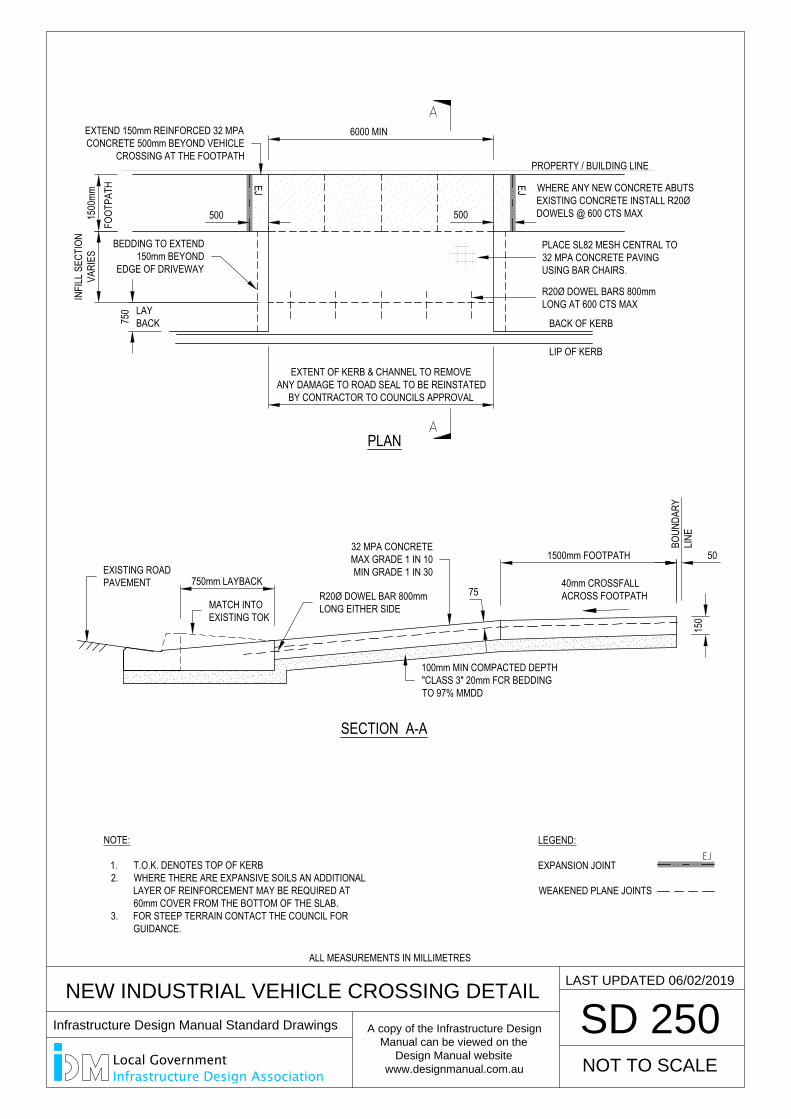
SD 250
500 500
NEW INDUSTRIAL VEHICLE CROSSING DETAIL
6000 MIN
EXTENT OF KERB & CHANNEL TO REMOVEANY DAMAGE TO ROAD SEAL TO BE REINSTATED
BY CONTRACTOR TO COUNCILS APPROVAL
WHERE ANY NEW CONCRETE ABUTSEXISTING CONCRETE INSTALL R20ØDOWELS @ 600 CTS MAX
NOT TO SCALE
LAST UPDATED 06/02/2019
1500mm FOOTPATH
150
40mm CROSSFALLACROSS FOOTPATH
SECTION A-A
PLAN
LEGEND:
EXPANSION JOINT
WEAKENED PLANE JOINTS
EJ EJ
1500
mmIN
FILL
SEC
TION
VARI
ESFO
OTPA
TH
PROPERTY / BUILDING LINE
750 LAY
BACK
LIP OF KERB
750mm LAYBACK
BACK OF KERB
75
50
BOUN
DARY
LINE
32 MPA CONCRETEMAX GRADE 1 IN 10MIN GRADE 1 IN 30
100mm MIN COMPACTED DEPTH"CLASS 3" 20mm FCR BEDDINGTO 97% MMDD
PLACE SL82 MESH CENTRAL TO32 MPA CONCRETE PAVINGUSING BAR CHAIRS.
MATCH INTOEXISTING TOK
R20Ø DOWEL BAR 800mmLONG EITHER SIDE
R20Ø DOWEL BARS 800mmLONG AT 600 CTS MAX
BEDDING TO EXTEND150mm BEYOND
EDGE OF DRIVEWAY
EXTEND 150mm REINFORCED 32 MPACONCRETE 500mm BEYOND VEHICLE
CROSSING AT THE FOOTPATH
NOTE:
1. T.O.K. DENOTES TOP OF KERB2. WHERE THERE ARE EXPANSIVE SOILS AN ADDITIONAL
LAYER OF REINFORCEMENT MAY BE REQUIRED AT60mm COVER FROM THE BOTTOM OF THE SLAB.
3. FOR STEEP TERRAIN CONTACT THE COUNCIL FORGUIDANCE.
EXISTING ROADPAVEMENT
ALL MEASUREMENTS IN MILLIMETRES
Infrastructure Design Manual Standard Drawings
A copy of the Infrastructure Design
Manual can be viewed on the
Design Manual website
www.designmanual.com.au
Local GovernmentInfrastructure Design Association
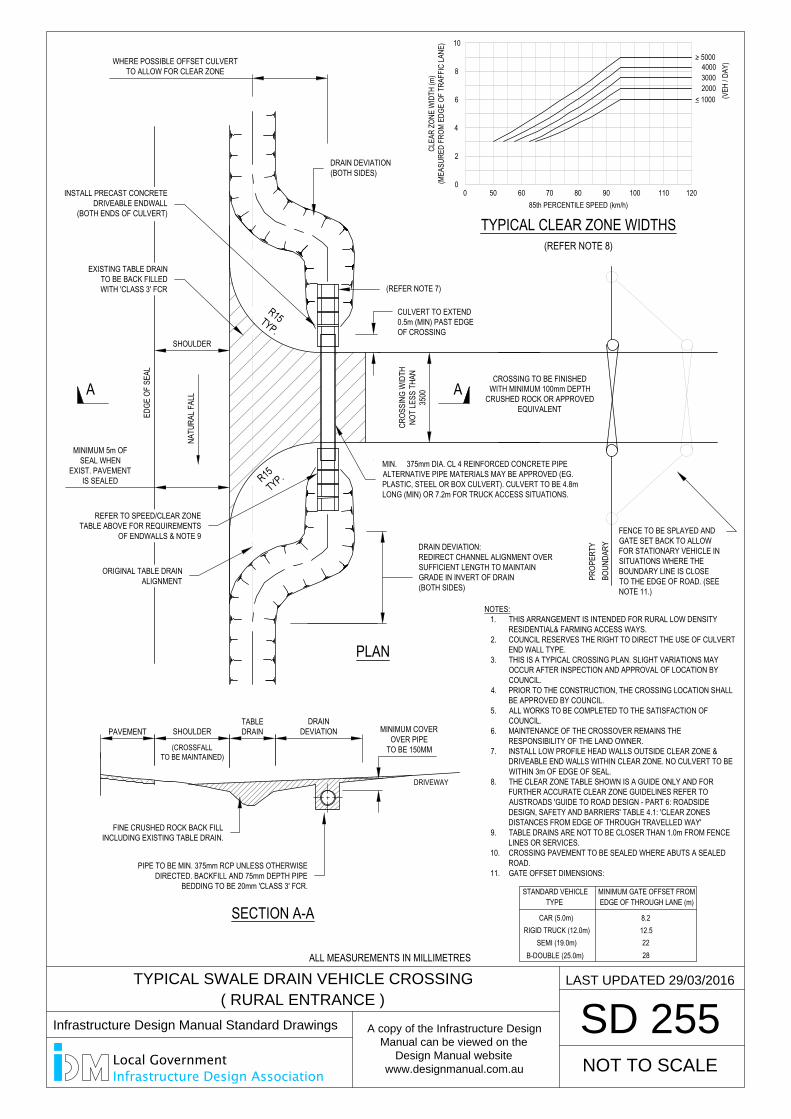
SD 255
EDGE
OF
SEAL
NATU
RAL F
ALL
DRIVEWAY
BOUN
DARY
SECTION A-A
PLAN
NOT TO SCALE
LAST UPDATED 29/03/2016
A A
PAVEMENT SHOULDERTABLEDRAIN
DRAINDEVIATION MINIMUM COVER
OVER PIPETO BE 150MM
TYPICAL CLEAR ZONE WIDTHS
0 50 60 70 80 90 100 110 1200
2
4
6
8
10
< 1000
> 5000
200030004000
(VEH
/ DAY
)
85th PERCENTILE SPEED (km/h)
CLEA
R ZO
NE W
IDTH
(m)
(MEA
SURE
D FR
OM E
DGE
OF T
RAFF
IC LA
NE)
(REFER NOTE 8)
DRAIN DEVIATION:REDIRECT CHANNEL ALIGNMENT OVERSUFFICIENT LENGTH TO MAINTAINGRADE IN INVERT OF DRAIN(BOTH SIDES)
MINIMUM 5m OFSEAL WHEN
EXIST. PAVEMENTIS SEALED
SHOULDER
CROS
SING
WID
THNO
T LE
SS T
HAN
3500
WHERE POSSIBLE OFFSET CULVERTTO ALLOW FOR CLEAR ZONE
NOTES:1. THIS ARRANGEMENT IS INTENDED FOR RURAL LOW DENSITY
RESIDENTIAL& FARMING ACCESS WAYS.2. COUNCIL RESERVES THE RIGHT TO DIRECT THE USE OF CULVERT
END WALL TYPE.3. THIS IS A TYPICAL CROSSING PLAN. SLIGHT VARIATIONS MAY
OCCUR AFTER INSPECTION AND APPROVAL OF LOCATION BYCOUNCIL.
4. PRIOR TO THE CONSTRUCTION, THE CROSSING LOCATION SHALLBE APPROVED BY COUNCIL.
5. ALL WORKS TO BE COMPLETED TO THE SATISFACTION OFCOUNCIL.
6. MAINTENANCE OF THE CROSSOVER REMAINS THERESPONSIBILITY OF THE LAND OWNER.
7. INSTALL LOW PROFILE HEAD WALLS OUTSIDE CLEAR ZONE &DRIVEABLE END WALLS WITHIN CLEAR ZONE. NO CULVERT TO BEWITHIN 3m OF EDGE OF SEAL.
8. THE CLEAR ZONE TABLE SHOWN IS A GUIDE ONLY AND FORFURTHER ACCURATE CLEAR ZONE GUIDELINES REFER TOAUSTROADS 'GUIDE TO ROAD DESIGN - PART 6: ROADSIDEDESIGN, SAFETY AND BARRIERS' TABLE 4.1: 'CLEAR ZONESDISTANCES FROM EDGE OF THROUGH TRAVELLED WAY'
9. TABLE DRAINS ARE NOT TO BE CLOSER THAN 1.0m FROM FENCELINES OR SERVICES.
10. CROSSING PAVEMENT TO BE SEALED WHERE ABUTS A SEALEDROAD.
11. GATE OFFSET DIMENSIONS:
CULVERT TO EXTEND0.5m (MIN) PAST EDGEOF CROSSING
CROSSING TO BE FINISHEDWITH MINIMUM 100mm DEPTH
CRUSHED ROCK OR APPROVEDEQUIVALENT
(CROSSFALLTO BE MAINTAINED)
R15TYP.
R15TYP.
RIGID TRUCK (12.0m)SEMI (19.0m)
B-DOUBLE (25.0m)
TYPESTANDARD VEHICLE
12.5
2822
EDGE OF THROUGH LANE (m)MINIMUM GATE OFFSET FROM
PROP
ERTY
TYPICAL SWALE DRAIN VEHICLE CROSSING
( RURAL ENTRANCE )
CAR (5.0m) 8.2
DRAIN DEVIATION(BOTH SIDES)
FENCE TO BE SPLAYED ANDGATE SET BACK TO ALLOWFOR STATIONARY VEHICLE INSITUATIONS WHERE THEBOUNDARY LINE IS CLOSETO THE EDGE OF ROAD. (SEENOTE 11.)
MIN. 375mm DIA. CL 4 REINFORCED CONCRETE PIPEALTERNATIVE PIPE MATERIALS MAY BE APPROVED (EG.PLASTIC, STEEL OR BOX CULVERT). CULVERT TO BE 4.8mLONG (MIN) OR 7.2m FOR TRUCK ACCESS SITUATIONS.
(REFER NOTE 7)
EXISTING TABLE DRAINTO BE BACK FILLEDWITH 'CLASS 3' FCR
INSTALL PRECAST CONCRETEDRIVEABLE ENDWALL
(BOTH ENDS OF CULVERT)
ORIGINAL TABLE DRAINALIGNMENT
REFER TO SPEED/CLEAR ZONETABLE ABOVE FOR REQUIREMENTS
OF ENDWALLS & NOTE 9
FINE CRUSHED ROCK BACK FILLINCLUDING EXISTING TABLE DRAIN.
PIPE TO BE MIN. 375mm RCP UNLESS OTHERWISEDIRECTED. BACKFILL AND 75mm DEPTH PIPE
BEDDING TO BE 20mm 'CLASS 3' FCR.
ALL MEASUREMENTS IN MILLIMETRES
Infrastructure Design Manual Standard Drawings
A copy of the Infrastructure Design
Manual can be viewed on the
Design Manual website
www.designmanual.com.au
Local GovernmentInfrastructure Design Association
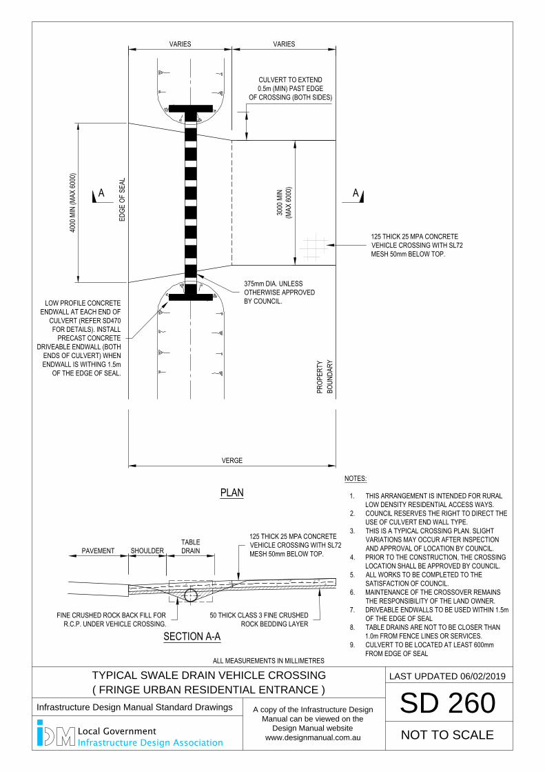
SD 260
NOT TO SCALE
LAST UPDATED 06/02/2019TYPICAL SWALE DRAIN VEHICLE CROSSING
( FRINGE URBAN RESIDENTIAL ENTRANCE )
4000
MIN
(MAX
6000
)
EDGE
OF
SEAL
BOUN
DARY
PR
OPER
TY
VERGE
A A
3000
MIN
(MAX
6000
)
SHOULDERTABLEDRAIN
SECTION A-A
PLAN
VARIES VARIES
NOTES:
1. THIS ARRANGEMENT IS INTENDED FOR RURALLOW DENSITY RESIDENTIAL ACCESS WAYS.
2. COUNCIL RESERVES THE RIGHT TO DIRECT THEUSE OF CULVERT END WALL TYPE.
3. THIS IS A TYPICAL CROSSING PLAN. SLIGHTVARIATIONS MAY OCCUR AFTER INSPECTIONAND APPROVAL OF LOCATION BY COUNCIL.
4. PRIOR TO THE CONSTRUCTION, THE CROSSINGLOCATION SHALL BE APPROVED BY COUNCIL.
5. ALL WORKS TO BE COMPLETED TO THESATISFACTION OF COUNCIL.
6. MAINTENANCE OF THE CROSSOVER REMAINSTHE RESPONSIBILITY OF THE LAND OWNER.
7. DRIVEABLE ENDWALLS TO BE USED WITHIN 1.5mOF THE EDGE OF SEAL
8. TABLE DRAINS ARE NOT TO BE CLOSER THAN1.0m FROM FENCE LINES OR SERVICES.
9. CULVERT TO BE LOCATED AT LEAST 600mmFROM EDGE OF SEAL
125 THICK 25 MPA CONCRETEVEHICLE CROSSING WITH SL72MESH 50mm BELOW TOP.
CULVERT TO EXTEND0.5m (MIN) PAST EDGE
OF CROSSING (BOTH SIDES)
LOW PROFILE CONCRETEENDWALL AT EACH END OF
CULVERT (REFER SD470FOR DETAILS). INSTALL
PRECAST CONCRETEDRIVEABLE ENDWALL (BOTH
ENDS OF CULVERT) WHENENDWALL IS WITHING 1.5m
OF THE EDGE OF SEAL.
PAVEMENT
FINE CRUSHED ROCK BACK FILL FORR.C.P. UNDER VEHICLE CROSSING.
50 THICK CLASS 3 FINE CRUSHEDROCK BEDDING LAYER
125 THICK 25 MPA CONCRETEVEHICLE CROSSING WITH SL72MESH 50mm BELOW TOP.
375mm DIA. UNLESSOTHERWISE APPROVEDBY COUNCIL.
ALL MEASUREMENTS IN MILLIMETRES
Infrastructure Design Manual Standard Drawings
A copy of the Infrastructure Design
Manual can be viewed on the
Design Manual website
www.designmanual.com.au
Local GovernmentInfrastructure Design Association
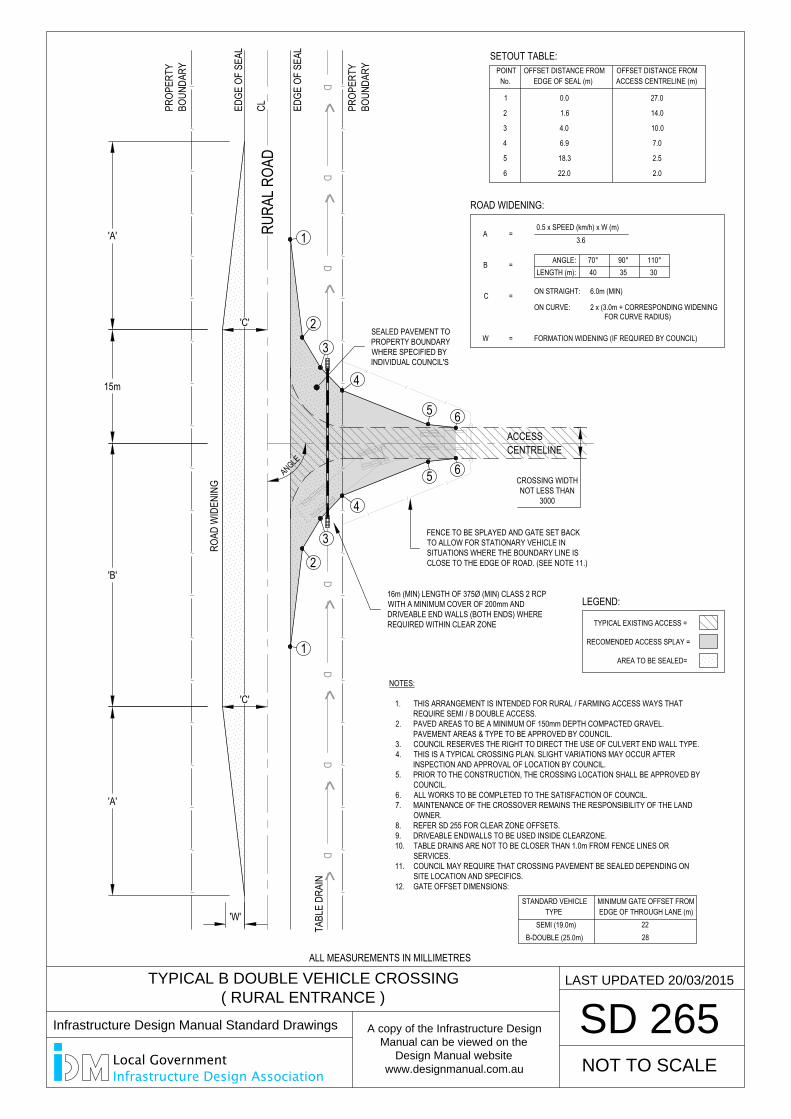
SD 265
NOT TO SCALE
LAST UPDATED 20/03/2015TYPICAL B DOUBLE VEHICLE CROSSING
( RURAL ENTRANCE )
D<
D<
D<
D<
D<
D<
D<
//
//
//
//
//
//
//
//
//
//
//
//
//
//
//
//
//
//
//
//
BOUN
DARY
PR
OPER
TY
BOUN
DARY
PR
OPER
TY
CROSSING WIDTHNOT LESS THAN
3000
EDGE
OF
SEAL
EDGE
OF
SEAL
CL
TABL
E DR
AIN
ACCESS
'A'
'A'
'B'
15m
RURA
L ROA
D
CENTRELINE
1
2
4
5 6
3/
/
/
/
/
/
NOTES:
1. THIS ARRANGEMENT IS INTENDED FOR RURAL / FARMING ACCESS WAYS THATREQUIRE SEMI / B DOUBLE ACCESS.
2. PAVED AREAS TO BE A MINIMUM OF 150mm DEPTH COMPACTED GRAVEL.PAVEMENT AREAS & TYPE TO BE APPROVED BY COUNCIL.
3. COUNCIL RESERVES THE RIGHT TO DIRECT THE USE OF CULVERT END WALL TYPE.4. THIS IS A TYPICAL CROSSING PLAN. SLIGHT VARIATIONS MAY OCCUR AFTER
INSPECTION AND APPROVAL OF LOCATION BY COUNCIL.5. PRIOR TO THE CONSTRUCTION, THE CROSSING LOCATION SHALL BE APPROVED BY
COUNCIL.6. ALL WORKS TO BE COMPLETED TO THE SATISFACTION OF COUNCIL.7. MAINTENANCE OF THE CROSSOVER REMAINS THE RESPONSIBILITY OF THE LAND
OWNER.8. REFER SD 255 FOR CLEAR ZONE OFFSETS.9. DRIVEABLE ENDWALLS TO BE USED INSIDE CLEARZONE.10. TABLE DRAINS ARE NOT TO BE CLOSER THAN 1.0m FROM FENCE LINES OR
SERVICES.11. COUNCIL MAY REQUIRE THAT CROSSING PAVEMENT BE SEALED DEPENDING ON
SITE LOCATION AND SPECIFICS.12. GATE OFFSET DIMENSIONS:
SEMI (19.0m)B-DOUBLE (25.0m)
TYPESTANDARD VEHICLE
2822
EDGE OF THROUGH LANE (m)MINIMUM GATE OFFSET FROM
0.0
EDGE OF SEAL (m)OFFSET DISTANCE FROM
ACCESS CENTRELINE (m)OFFSET DISTANCE FROM
No.POINT
1
1
2
4
5 6
3
27.0
1.62 14.0
4.03 10.0
6.94 7.0
18.35 2.5
22.06 2.0
SETOUT TABLE:
0.5 x SPEED (km/h) x W (m)A
LENGTH (m):B
ROAD WIDENING:RO
AD W
IDEN
ING
ANGLE
'C'
'C'
'W'
3.6=
ANGLE:4070°
3590°
30110°=
C =ON CURVE:
ON STRAIGHT:
2 x (3.0m + CORRESPONDING WIDENING
6.0m (MIN)
FOR CURVE RADIUS)
W = FORMATION WIDENING (IF REQUIRED BY COUNCIL)
LEGEND:
TYPICAL EXISTING ACCESS =
RECOMENDED ACCESS SPLAY =
AREA TO BE SEALED=
FENCE TO BE SPLAYED AND GATE SET BACKTO ALLOW FOR STATIONARY VEHICLE INSITUATIONS WHERE THE BOUNDARY LINE ISCLOSE TO THE EDGE OF ROAD. (SEE NOTE 11.)
16m (MIN) LENGTH OF 375Ø (MIN) CLASS 2 RCPWITH A MINIMUM COVER OF 200mm ANDDRIVEABLE END WALLS (BOTH ENDS) WHEREREQUIRED WITHIN CLEAR ZONE
SEALED PAVEMENT TOPROPERTY BOUNDARYWHERE SPECIFIED BYINDIVIDUAL COUNCIL'S
ALL MEASUREMENTS IN MILLIMETRES
Infrastructure Design Manual Standard Drawings
A copy of the Infrastructure Design
Manual can be viewed on the
Design Manual website
www.designmanual.com.au
Local GovernmentInfrastructure Design Association
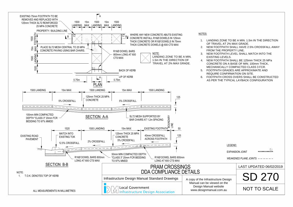
SD 270
LAST UPDATED 06/02/2019
NOT TO SCALE
PRAM CROSSINGSDDA COMPLIANCE DETAILS
NOTE:1. T.O.K. DENOTES TOP OF KERB
WHERE ANY NEW CONCRETE ABUTS EXISTINGCONCRETE INSTALL R16Ø DOWELS IN 125mmTHICK CONCRETE OR R10Ø DOWELS IN 75mmTHICK CONCRETE DOWELS @ 600 CTS MAX
PLAN
A
A
1500
FOOT
PATH
1500
LAND
ING
PROPERTY / BUILDING LINE15
20
LIP OF KERB
EXISTING FOOTPATH
125
SECTION B-B
40mm CROSSFALLACROSS FOOTPATH
BACK OF KERB
50BOUN
DARY
LINE
125mm THICK 25 MPACONCRETE
50mm MIN COMPACTED DEPTH"CLASS 3" 20mm FCR BEDDINGTO 97% MMDD
PLACE SL72 MESH CENTRAL TO 25 MPACONCRETE PAVING USING BAR CHAIRS.
MATCH INTOEXISTING TOKEXISTING ROAD
PAVEMENT
EXISTING 75mm FOOTPATH TO BEREMOVED AND REPLACED WITH125mm THICK SL72 REINFORCED
25 MPA CONCRETE
R16Ø DOWEL BARS800mm LONG AT 600CTS MAX
NOTES:
1. LANDING ZONE TO BE A MIN. 1.5m IN THE DIRECTION
OF TRAVEL AT 2% MAX GRADE.
2. NEW FOOTPATH SHALL HAVE 2.5% CROSSFALL AWAY
FROM THE PROPERTY LINE.
3. NEW FOOTPATH LEVEL SHALL MATCH INTO THE
EXISTING LEVELS.
4. NEW FOOTPATH SHALL BE 125mm THICK 25 MPa
CONCRETE ON A BASE OF MIN. 100mm THICK,
MECHANICALLY COMPACTED CLASS 3 FCR.
5. FOOTPATH GRADES ARE APPROXIMATE AND
REQUIRE CONFIRMATION ON SITE.
6. FOOTPATH CROSS OVERS SHALL BE CONSTRUCTED
AS PER THE TYPICAL LAYBACK CONFIGURATION
15m MAX1500 LANDING1520
5% CROSSFALL2% CROSSFALL12.5% CROSSFALL
125125mm THICK 25 MPACONCRETE
15m MAX15m MAX
5% CROSSFALL
1500 LANDING 1500 LANDING1500 LANDING
SL72 MESH SUPPORTED BYBAR CHAIRS AT 1.2m SPACING
SECTION A-A
15m
MAX
EJ
R16Ø DOWEL BARS 800mmLONG AT 600 CTS MAX
R16Ø DOWEL BARS 800mmLONG AT 600 CTS MAX
B B
EJ
LEGEND:
EXPANSION JOINT
WEAKENED PLANE JOINTS
NOTE:LANDING ZONE TO BE A MIN.
1.5m IN THE DIRECTION OF
TRAVEL AT 2% MAX GRADE.
EJ
EJ
1500LANDING
15mMAX
1500LANDING
15mMAX
1500LANDING
5% CROSSFALL
0.75m 0.75m
100mm MIN COMPACTEDDEPTH "CLASS 3" 20mm FCRBEDDING TO 97% MMDD
SD 270
LAST UPDATED 06/02/2019
NOT TO SCALE
PRAM CROSSINGSDDA COMPLIANCE DETAILS
ALL MEASUREMENTS IN MILLIMETRES
Infrastructure Design Manual Standard Drawings
A copy of the Infrastructure Design
Manual can be viewed on the
Design Manual website
www.designmanual.com.au
Local GovernmentInfrastructure Design Association
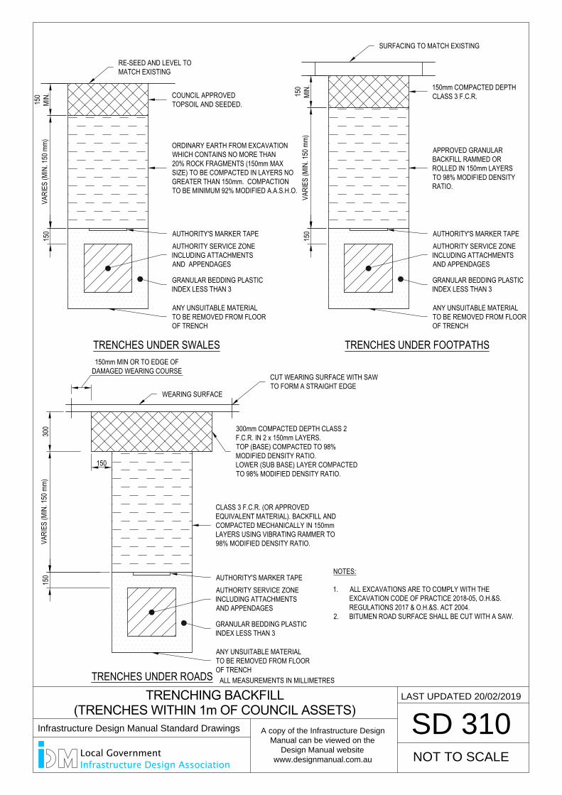
150
MIN.
300
TRENCHING BACKFILL
(TRENCHES WITHIN 1m OF COUNCIL ASSETS)
SD 310
LAST UPDATED 20/02/2019
VARI
ES (M
IN. 1
50 m
m)15
0
ANY UNSUITABLE MATERIALTO BE REMOVED FROM FLOOROF TRENCH
GRANULAR BEDDING PLASTICINDEX LESS THAN 3
AUTHORITY SERVICE ZONEINCLUDING ATTACHMENTSAND APPENDAGES
AUTHORITY'S MARKER TAPE
150
MIN.
VARI
ES (M
IN. 1
50 m
m)15
0
TRENCHES UNDER FOOTPATHS
150mm COMPACTED DEPTHCLASS 3 F.C.R.
ANY UNSUITABLE MATERIALTO BE REMOVED FROM FLOOROF TRENCH
GRANULAR BEDDING PLASTICINDEX LESS THAN 3
AUTHORITY SERVICE ZONEINCLUDING ATTACHMENTSAND APPENDAGES
AUTHORITY'S MARKER TAPE
APPROVED GRANULARBACKFILL RAMMED ORROLLED IN 150mm LAYERSTO 98% MODIFIED DENSITYRATIO.
SURFACING TO MATCH EXISTINGVA
RIES
(MIN
. 150
mm)
150
TRENCHES UNDER SWALES
COUNCIL APPROVEDTOPSOIL AND SEEDED.
ANY UNSUITABLE MATERIALTO BE REMOVED FROM FLOOROF TRENCH
GRANULAR BEDDING PLASTICINDEX LESS THAN 3
AUTHORITY SERVICE ZONEINCLUDING ATTACHMENTSAND APPENDAGES
AUTHORITY'S MARKER TAPE
ORDINARY EARTH FROM EXCAVATIONWHICH CONTAINS NO MORE THAN20% ROCK FRAGMENTS (150mm MAXSIZE) TO BE COMPACTED IN LAYERS NOGREATER THAN 150mm. COMPACTIONTO BE MINIMUM 92% MODIFIED A.A.S.H.O.
RE-SEED AND LEVEL TOMATCH EXISTING
NOT TO SCALE
150
150mm MIN OR TO EDGE OFDAMAGED WEARING COURSE
WEARING SURFACE
TRENCHES UNDER ROADS
300mm COMPACTED DEPTH CLASS 2F.C.R. IN 2 x 150mm LAYERS.TOP (BASE) COMPACTED TO 98%MODIFIED DENSITY RATIO.LOWER (SUB BASE) LAYER COMPACTEDTO 98% MODIFIED DENSITY RATIO.
CLASS 3 F.C.R. (OR APPROVEDEQUIVALENT MATERIAL). BACKFILL ANDCOMPACTED MECHANICALLY IN 150mmLAYERS USING VIBRATING RAMMER TO98% MODIFIED DENSITY RATIO.
CUT WEARING SURFACE WITH SAWTO FORM A STRAIGHT EDGE
NOTES:
1. ALL EXCAVATIONS ARE TO COMPLY WITH THEEXCAVATION CODE OF PRACTICE 2018-05, O.H.&S.REGULATIONS 2017 & O.H.&S. ACT 2004.
2. BITUMEN ROAD SURFACE SHALL BE CUT WITH A SAW.
ALL MEASUREMENTS IN MILLIMETRES
Infrastructure Design Manual Standard Drawings
A copy of the Infrastructure Design
Manual can be viewed on the
Design Manual website
www.designmanual.com.au
Local GovernmentInfrastructure Design Association
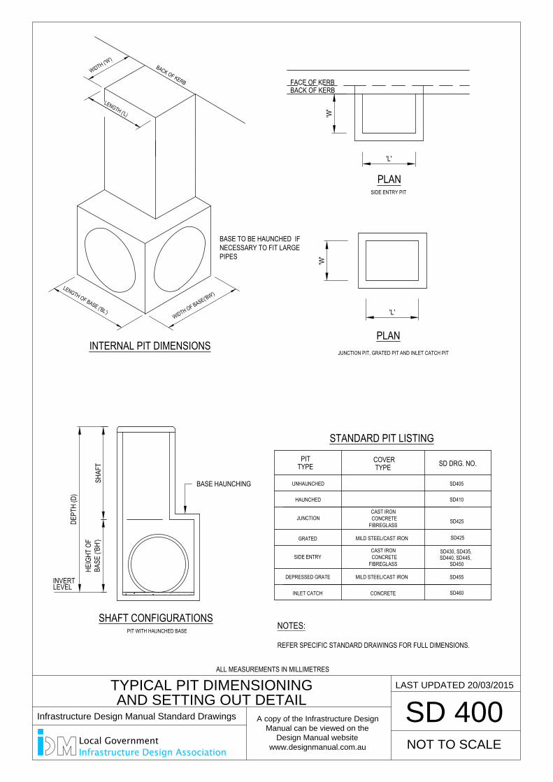
SIDE ENTRY
JUNCTION
HAUNCHED
UNHAUNCHED
PITTYPE
GRATED
INLET CATCH
SHAFT CONFIGURATIONSPIT WITH HAUNCHED BASE
SD460CONCRETE
SD450SD440, SD445,SD430, SD435,
JUNCTION PIT, GRATED PIT AND INLET CATCH PIT
CAST IRON
MILD STEEL/CAST IRON
CONCRETE
COVERTYPE SD DRG. NO.
STANDARD PIT LISTING
PLAN'W
''L'
HEIG
HT O
FBA
SE ('B
H')
SHAF
T
DEPT
H (D
)
DEPRESSED GRATE SD455MILD STEEL/CAST IRON
TYPICAL PIT DIMENSIONING
AND SETTING OUT DETAIL
SD 400
INTERNAL PIT DIMENSIONS
BASE TO BE HAUNCHED IFNECESSARY TO FIT LARGEPIPES
PLANSIDE ENTRY PIT
BACK OF KERBFACE OF KERB
'W'
'L'
WIDTH ('W')
BACK OF KERB
LENGTH ('L)
SD405
SD410
SD425
SD425
WIDTH OF BASE('BW')LENGTH OF BASE ('BL')
NOTES:
REFER SPECIFIC STANDARD DRAWINGS FOR FULL DIMENSIONS.
LAST UPDATED 20/03/2015
FIBREGLASS
CAST IRONCONCRETE
FIBREGLASS
NOT TO SCALE
BASE HAUNCHING
INVERTLEVEL
ALL MEASUREMENTS IN MILLIMETRES
Infrastructure Design Manual Standard Drawings
A copy of the Infrastructure Design
Manual can be viewed on the
Design Manual website
www.designmanual.com.au
Local GovernmentInfrastructure Design Association
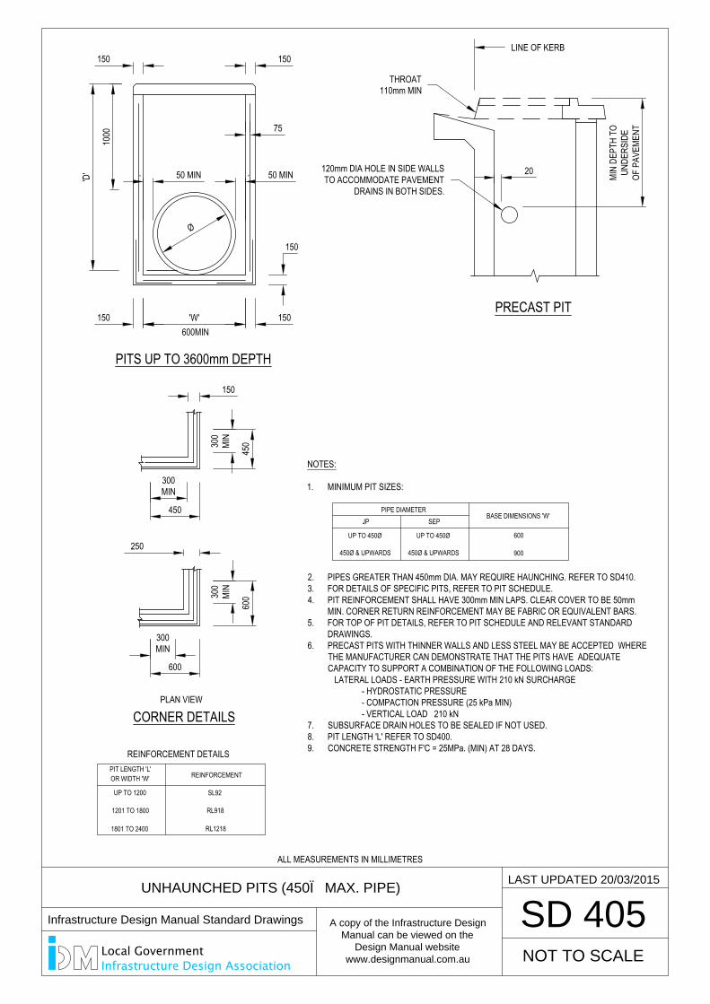
UNHAUNCHED PITS (450Ø MAX. PIPE)
SD 405
PITS UP TO 3600mm DEPTH
REINFORCEMENT
REINFORCEMENT DETAILS
UP TO 1200
1201 TO 1800
1801 TO 2400
OR WIDTH 'W'PIT LENGTH 'L'
SL92
RL1218
RL918
PRECAST PIT
50 MIN
'W'
Ø
'D' 50 MIN
150
75
150
150
150
150
NOTES:
1. MINIMUM PIT SIZES:
2. PIPES GREATER THAN 450mm DIA. MAY REQUIRE HAUNCHING. REFER TO SD410.3. FOR DETAILS OF SPECIFIC PITS, REFER TO PIT SCHEDULE.4. PIT REINFORCEMENT SHALL HAVE 300mm MIN LAPS. CLEAR COVER TO BE 50mm
MIN. CORNER RETURN REINFORCEMENT MAY BE FABRIC OR EQUIVALENT BARS.5. FOR TOP OF PIT DETAILS, REFER TO PIT SCHEDULE AND RELEVANT STANDARD
DRAWINGS.6. PRECAST PITS WITH THINNER WALLS AND LESS STEEL MAY BE ACCEPTED WHERE
THE MANUFACTURER CAN DEMONSTRATE THAT THE PITS HAVE ADEQUATECAPACITY TO SUPPORT A COMBINATION OF THE FOLLOWING LOADS:
LATERAL LOADS - EARTH PRESSURE WITH 210 kN SURCHARGE- HYDROSTATIC PRESSURE- COMPACTION PRESSURE (25 kPa MIN)- VERTICAL LOAD 210 kN
7. SUBSURFACE DRAIN HOLES TO BE SEALED IF NOT USED.8. PIT LENGTH 'L' REFER TO SD400.9. CONCRETE STRENGTH F'C = 25MPa. (MIN) AT 28 DAYS.
600
BASE DIMENSIONS 'W'SEP
900
PLAN VIEW
CORNER DETAILS
450
300MIN
45030
0MI
N
150
600
300MIN
60030
0MI
N
250
20 MIN
DEPT
H TO
UNDE
RSID
EOF
PAV
EMEN
T
PIPE DIAMETERJP
1000
600MIN
LAST UPDATED 20/03/2015
UP TO 450Ø
450Ø & UPWARDS
UP TO 450Ø
450Ø & UPWARDS
NOT TO SCALE
120mm DIA HOLE IN SIDE WALLSTO ACCOMMODATE PAVEMENT
DRAINS IN BOTH SIDES.
THROAT110mm MIN
LINE OF KERB
ALL MEASUREMENTS IN MILLIMETRES
Infrastructure Design Manual Standard Drawings
A copy of the Infrastructure Design
Manual can be viewed on the
Design Manual website
www.designmanual.com.au
Local GovernmentInfrastructure Design Association
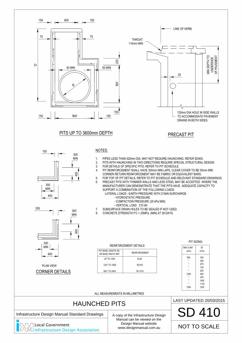
HAUNCHED PITS
SD 410
PITS UP TO 3600mm DEPTH
(mm)(mm)
"1500
""
1200
11251200
9751050
900""""
900600
750825
675
525
'BW' & 'BH'
CORNER DETAILS
'Ø'
NOTES:
1. PIPES LESS THAN 525mm DIA. MAY NOT REQUIRE HAUNCHING. REFER SD405.2. PITS WITH HAUNCHING IN TWO DIRECTIONS REQUIRE SPECIAL STRUCTURAL DESIGN.3. FOR DETAILS OF SPECIFIC PITS, REFER TO PIT SCHEDULE.4. PIT REINFORCEMENT SHALL HAVE 300mm MIN LAPS. CLEAR COVER TO BE 50mm MIN.
CORNER RETURN REINFORCEMENT MAY BE FABRIC OR EQUIVALENT BARS.5. FOR TOP OF PIT DETAILS, REFER TO PIT SCHEDULE AND RELEVANT STANDARD DRAWINGS.6. PRECAST PITS WITH THINNER WALLS AND LESS STEEL MAY BE ACCEPTED WHERE THE
MANUFACTURER CAN DEMONSTRATE THAT THE PITS HAVE ADEQUATE CAPACITY TOSUPPORT A COMBINATION OF THE FOLLOWING LOADS:
LATERAL LOADS - EARTH PRESSURE WITH 210kN SURCHARGE- HYDROSTATIC PRESSURE- COMPACTION PRESSURE (25 kPa MIN)- VERTICAL LOAD 210 kN
7. SUBSURFACE DRAIN HOLES TO BE SEALED IF NOT USED.8. CONCRETE STRENGTH F'C = 25MPa. (MIN) AT 28 DAYS.
150 600 150
75 75
225
'BH'
150
50 MIN 50 MIN
'D'
150 'BW' 150
150
450
300MIN
450
300MIN
250
600
300MIN
600
300MIN
Ø
PRECAST PIT
20
PLAN VIEW
REINFORCEMENT
REINFORCEMENT DETAILS
UP TO 1200
1201 TO 1800
1801 TO 2400
OR BASE WIDTH 'BW'PIT BASE LENGTH 'BL'
SL92
RL1218
RL918
MIN
DEPT
H TO
UNDE
RSID
EOF
PAV
EMEN
T
LAST UPDATED 20/03/2015
PIT SIZING
NOT TO SCALE
THROAT110mm MIN
LINE OF KERB
120mm DIA HOLE IN SIDE WALLSTO ACCOMMODATE PAVEMENTDRAINS IN BOTH SIDES.
ALL MEASUREMENTS IN MILLIMETRES
Infrastructure Design Manual Standard Drawings
A copy of the Infrastructure Design
Manual can be viewed on the
Design Manual website
www.designmanual.com.au
Local GovernmentInfrastructure Design Association
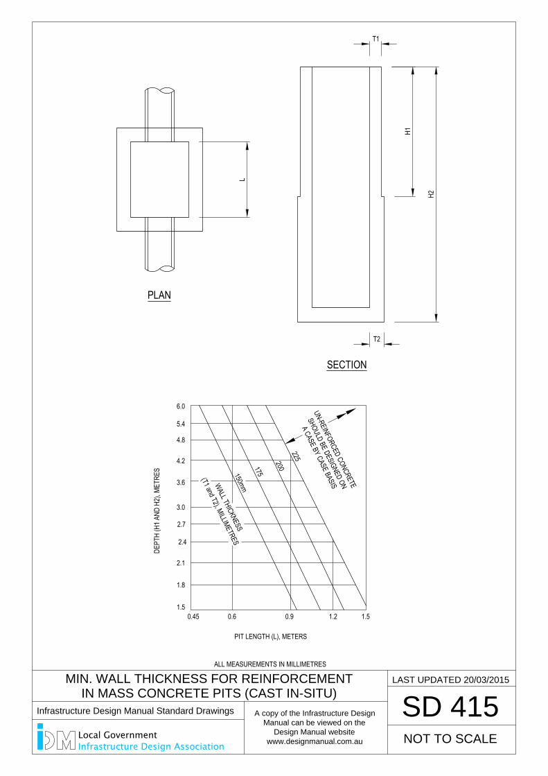
PIT LENGTH (L), METERS
(T1 and T2), MILLIMETRES
DEPT
H (H
1 AND
H2)
, MET
RES
1.50.45
1.8
2.4
2.1
2.7
3.6
3.0
4.2
5.4
4.8
6.0
WALL THICKNESS
0.6 0.9 1.2
200
150mm
175
225
1.5
L
T1
H1
H2
T2
MIN. WALL THICKNESS FOR REINFORCEMENT
IN MASS CONCRETE PITS (CAST IN-SITU)
SD 415
LAST UPDATED 20/03/2015
PLAN
SECTION
UN-REINFORCED CONCRETE
SHOULD BE DESIGNED ON
A CASE BY CASE BASIS
NOT TO SCALE
ALL MEASUREMENTS IN MILLIMETRES
Infrastructure Design Manual Standard Drawings
A copy of the Infrastructure Design
Manual can be viewed on the
Design Manual website
www.designmanual.com.au
Local GovernmentInfrastructure Design Association
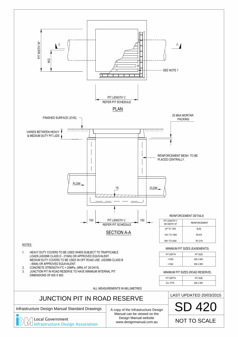
REFER PIT SCHEDULE
PLAN
150 PIT LENGTH 'L' 150
SEE NOTE 1
PIT LENGTH 'L'
75
W/2PI
T W
IDTH
'W'
VARIES BETWEEN HEAVY& MEDIUM DUTY PIT LIDS
JUNCTION PIT IN ROAD RESERVE
SD 420
REFER PIT SCHEDULE
FLOWFLOW
SECTION A-A
REINFORCEMENT
REINFORCEMENT DETAILS
UP TO 1200
1201 TO 1800
1801 TO 2400
OR WIDTH 'W'PIT LENGTH 'L'
SL92
RL1218
RL918
NOTES:
1. HEAVY DUTY COVERS TO BE USED WHEN SUBJECT TO TRAFFICABLELOADS (AS3996 CLASS D - 210kN) OR APPROVED EQUIVALENT.MEDIUM DUTY COVERS TO BE USED IN OFF ROAD USE (AS3996 CLASS B- 80kN) OR APPROVED EQUIVALENT.
2. CONCRETE STRENGTH F'C = 25MPa. (MIN) AT 28 DAYS.3. JUNCTION PIT IN ROAD RESERVE TO HAVE MINIMUM INTERNAL PIT
DIMENSIONS OF 600 X 900.
LAST UPDATED 20/03/2015
25 MAX MORTAR PACKING
PIT SIZE
MINIMUM PIT SIZES (EASEMENTS)
<1000
>1000
PIT DEPTH
600 x 600
600 x 900
PIT SIZE
MINIMUM PIT SIZES (ROAD RESERVE)
ALL PITS
PIT DEPTH
600 x 900
NOT TO SCALE
REINFORCEMENT MESH TO BEPLACED CENTRALLY.
FINISHED SURFACE LEVEL
ALL MEASUREMENTS IN MILLIMETRES
Infrastructure Design Manual Standard Drawings
A copy of the Infrastructure Design
Manual can be viewed on the
Design Manual website
www.designmanual.com.au
Local GovernmentInfrastructure Design Association
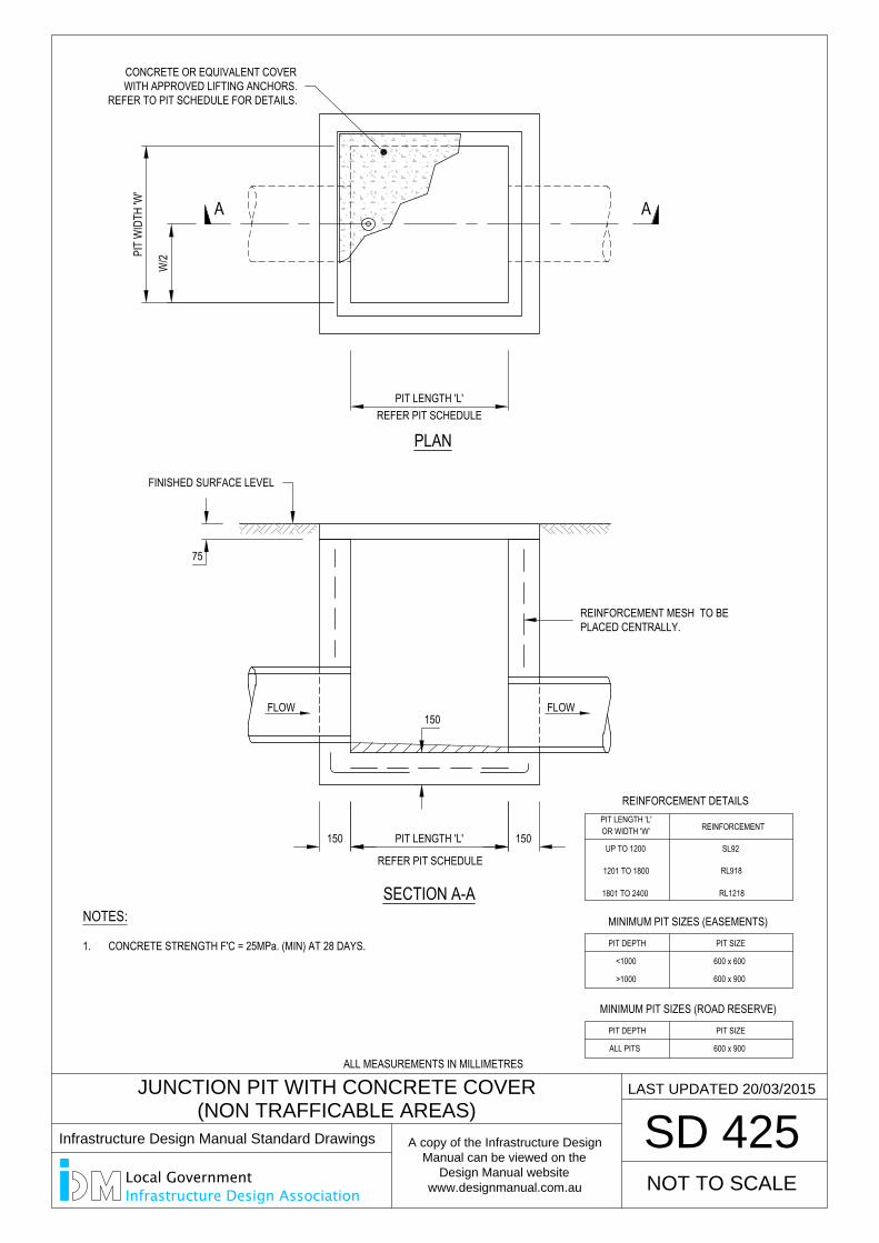
REFER PIT SCHEDULE
PLAN
75
150 PIT LENGTH 'L' 150
PIT LENGTH 'L'
150
PIT
WID
TH 'W
'
W/2
JUNCTION PIT WITH CONCRETE COVER
(NON TRAFFICABLE AREAS)
SD 425
REFER PIT SCHEDULE
REINFORCEMENT
REINFORCEMENT DETAILS
UP TO 1200
1201 TO 1800
1801 TO 2400
OR WIDTH 'W'PIT LENGTH 'L'
SL92
RL1218
RL918
A A
SECTION A-A
FLOW FLOW
LAST UPDATED 20/03/2015
NOTES:
1. CONCRETE STRENGTH F'C = 25MPa. (MIN) AT 28 DAYS. PIT SIZE
MINIMUM PIT SIZES (EASEMENTS)
<1000
>1000
PIT DEPTH
600 x 600
600 x 900
PIT SIZE
MINIMUM PIT SIZES (ROAD RESERVE)
ALL PITS
PIT DEPTH
600 x 900
NOT TO SCALE
REINFORCEMENT MESH TO BEPLACED CENTRALLY.
FINISHED SURFACE LEVEL
CONCRETE OR EQUIVALENT COVERWITH APPROVED LIFTING ANCHORS.
REFER TO PIT SCHEDULE FOR DETAILS.
ALL MEASUREMENTS IN MILLIMETRES
Infrastructure Design Manual Standard Drawings
A copy of the Infrastructure Design
Manual can be viewed on the
Design Manual website
www.designmanual.com.au
Local GovernmentInfrastructure Design Association
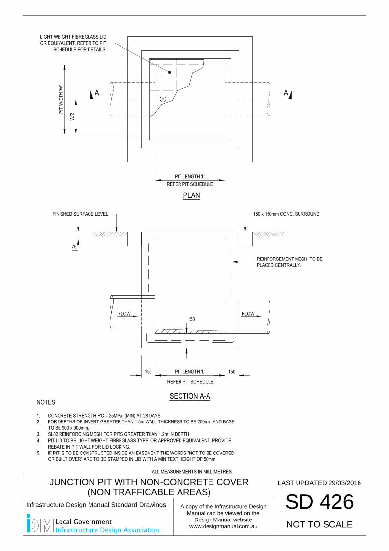
REFER PIT SCHEDULE
PLAN
75
150 PIT LENGTH 'L' 150
PIT LENGTH 'L'
150
PIT
WID
TH 'W
'
W/2
JUNCTION PIT WITH NON-CONCRETE COVER
(NON TRAFFICABLE AREAS)
SD 426
REFER PIT SCHEDULE
A A
SECTION A-A
FLOW FLOW
LAST UPDATED 29/03/2016
NOTES:
1. CONCRETE STRENGTH F'C = 25MPa. (MIN) AT 28 DAYS.2. FOR DEPTHS OF INVERT GREATER THAN 1.5m WALL THICKNESS TO BE 200mm AND BASE
TO BE 900 x 900mm.3. SL82 REINFORCING MESH FOR PITS GREATER THAN 1.2m IN DEPTH4. PIT LID TO BE LIGHT WEIGHT FIBREGLASS TYPE, OR APPROVED EQUIVALENT. PROVIDE
REBATE IN PIT WALL FOR LID LOCKING.5. IF PIT IS TO BE CONSTRUCTED INSIDE AN EASEMENT THE WORDS "NOT TO BE COVERED
OR BUILT OVER" ARE TO BE STAMPED IN LID WITH A MIN TEXT HEIGHT OF 50mm.
NOT TO SCALE
REINFORCEMENT MESH TO BEPLACED CENTRALLY.
FINISHED SURFACE LEVEL 150 x 150mm CONC. SURROUND
LIGHT WEIGHT FIBREGLASS LIDOR EQUIVALENT. REFER TO PIT
SCHEDULE FOR DETAILS.
ALL MEASUREMENTS IN MILLIMETRES
Infrastructure Design Manual Standard Drawings
A copy of the Infrastructure Design
Manual can be viewed on the
Design Manual website
www.designmanual.com.au
Local GovernmentInfrastructure Design Association
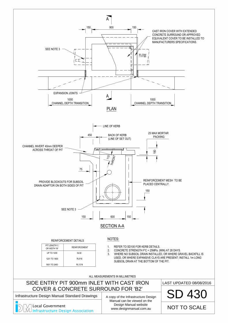
PLAN
75
1000CHANNEL DEPTH TRANSITION
450 BACK OF KERB(LINE OF SET OUT)
150 600 150
150
900150 150
110
SIDE ENTRY PIT 900mm INLET WITH CAST IRON
COVER & CONCRETE SURROUND FOR 'B2'
SD 430
FLOW
REINFORCEMENT
REINFORCEMENT DETAILS
UP TO 1200
1201 TO 1800
1801 TO 2400
OR WIDTH 'W'PIT LENGTH 'L'
SL92
RL1218
RL918
A
A
SECTION A-A
EXPANSION JOINTS
1000CHANNEL DEPTH TRANSITION
LINE OF KERB
NOTES:
1. REFER TO SD100 FOR KERB DETAILS.2. CONCRETE STRENGTH F'C = 25MPa. (MIN) AT 28 DAYS.3. WHERE NO SUBSOIL DRAIN INSTALLED, OR WHERE GRAVEL BACKFILL IS
USED, OR WHERE EXPANSIVE CLAYS ARE PRESENT; INSTALL 1m LONGSUBSOIL DRAIN AT THE BOTTOM OF THE PIT.
THRO
AT
LAST UPDATED 08/08/2016
180
25 MAX MORTAR PACKING
NOT TO SCALE
REINFORCEMENT MESH TO BEPLACED CENTRALLY.
CAST IRON COVER WITH EXTENDEDCONCRETE SURROUND OR APPROVEDEQUIVALENT COVER TO BE INSTALLED TOMANUFACTURERS SPECIFICATIONS.
SEE NOTE 3
CHANNEL INVERT 40mm DEEPERACROSS THROAT OF PIT
PROVIDE BLOCKOUTS FOR SUBSOILDRAIN ADAPTOR ON BOTH SIDES OF PIT
SEE NOTE 3
ALL MEASUREMENTS IN MILLIMETRES
Infrastructure Design Manual Standard Drawings
A copy of the Infrastructure Design
Manual can be viewed on the
Design Manual website
www.designmanual.com.au
Local GovernmentInfrastructure Design Association
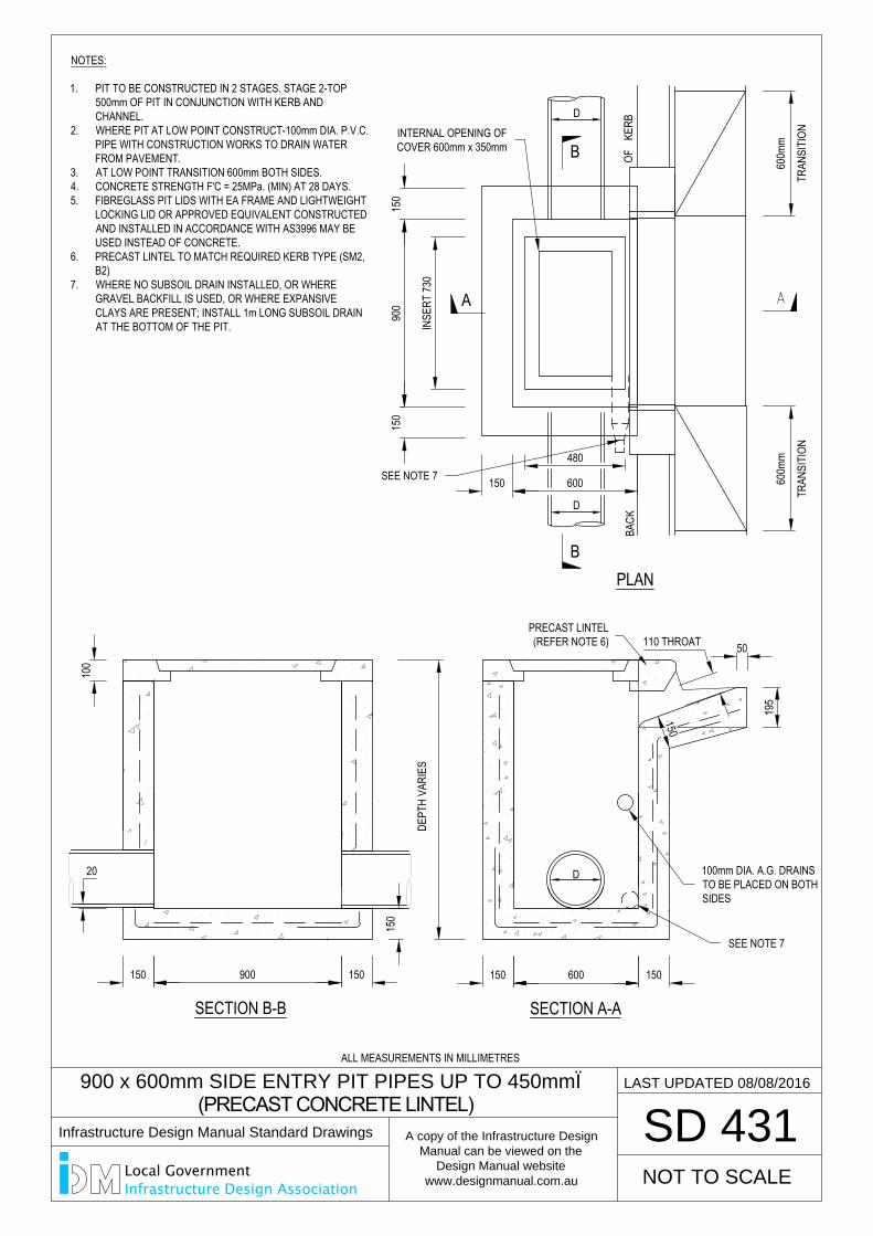
900 x 600mm SIDE ENTRY PIT PIPES UP TO 450mmØ
(PRECAST CONCRETE LINTEL)
SD 431
150 150600
D
150
900
150
150 600
INSE
RT 73
0
480
BACK
OFKE
RB
PLAN
SECTION A-A
600m
m
TRAN
SITI
ON
195
DEPT
H VA
RIES
150 900 150
100
SECTION B-B
D
D
50
600m
m
TRAN
SITI
ON
NOT TO SCALE
B
B
A
110 THROATPRECAST LINTEL(REFER NOTE 6)
20
150
150
LAST UPDATED 08/08/2016
NOTES:
1. PIT TO BE CONSTRUCTED IN 2 STAGES. STAGE 2-TOP500mm OF PIT IN CONJUNCTION WITH KERB ANDCHANNEL.
2. WHERE PIT AT LOW POINT CONSTRUCT-100mm DIA. P.V.C.PIPE WITH CONSTRUCTION WORKS TO DRAIN WATERFROM PAVEMENT.
3. AT LOW POINT TRANSITION 600mm BOTH SIDES.4. CONCRETE STRENGTH F'C = 25MPa. (MIN) AT 28 DAYS.5. FIBREGLASS PIT LIDS WITH EA FRAME AND LIGHTWEIGHT
LOCKING LID OR APPROVED EQUIVALENT CONSTRUCTEDAND INSTALLED IN ACCORDANCE WITH AS3996 MAY BEUSED INSTEAD OF CONCRETE.
6. PRECAST LINTEL TO MATCH REQUIRED KERB TYPE (SM2,B2)
7. WHERE NO SUBSOIL DRAIN INSTALLED, OR WHEREGRAVEL BACKFILL IS USED, OR WHERE EXPANSIVECLAYS ARE PRESENT; INSTALL 1m LONG SUBSOIL DRAINAT THE BOTTOM OF THE PIT.
100mm DIA. A.G. DRAINSTO BE PLACED ON BOTHSIDES
SEE NOTE 7
SEE NOTE 7
INTERNAL OPENING OFCOVER 600mm x 350mm
ALL MEASUREMENTS IN MILLIMETRES
Infrastructure Design Manual Standard Drawings
A copy of the Infrastructure Design
Manual can be viewed on the
Design Manual website
www.designmanual.com.au
Local GovernmentInfrastructure Design Association
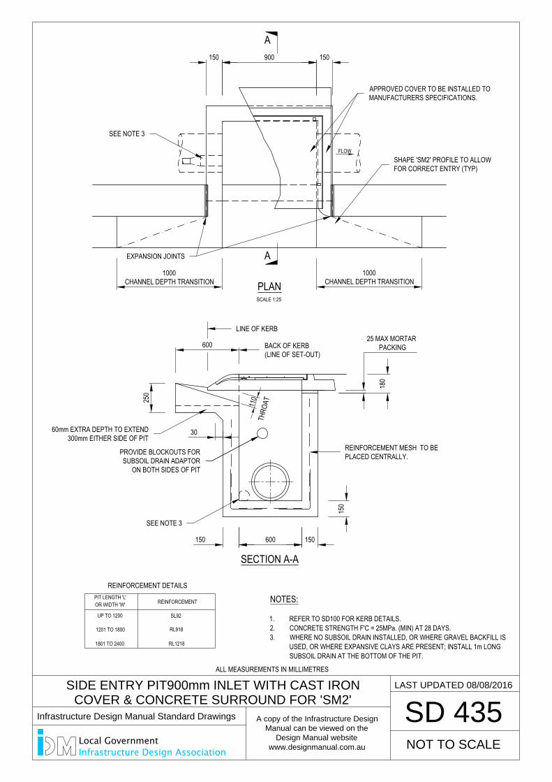
600
FLOW25
0
SCALE 1:25
PLAN
30
110
150 900 150
1000CHANNEL DEPTH TRANSITION
1000CHANNEL DEPTH TRANSITION
BACK OF KERB(LINE OF SET-OUT)
150
150 600 150
SIDE ENTRY PIT900mm INLET WITH CAST IRON
COVER & CONCRETE SURROUND FOR 'SM2'
SD 435
REINFORCEMENT
REINFORCEMENT DETAILS
UP TO 1200
1201 TO 1800
1801 TO 2400
OR WIDTH 'W'PIT LENGTH 'L'
SL92
RL1218
RL918
THRO
AT
SECTION A-A
A
A
LAST UPDATED 08/08/2016
180
25 MAX MORTAR PACKING
NOTES:
1. REFER TO SD100 FOR KERB DETAILS.2. CONCRETE STRENGTH F'C = 25MPa. (MIN) AT 28 DAYS.3. WHERE NO SUBSOIL DRAIN INSTALLED, OR WHERE GRAVEL BACKFILL IS
USED, OR WHERE EXPANSIVE CLAYS ARE PRESENT; INSTALL 1m LONGSUBSOIL DRAIN AT THE BOTTOM OF THE PIT.
NOT TO SCALE
REINFORCEMENT MESH TO BEPLACED CENTRALLY.
APPROVED COVER TO BE INSTALLED TOMANUFACTURERS SPECIFICATIONS.
60mm EXTRA DEPTH TO EXTEND300mm EITHER SIDE OF PIT
SEE NOTE 3
SHAPE 'SM2' PROFILE TO ALLOWFOR CORRECT ENTRY (TYP)
EXPANSION JOINTS
PROVIDE BLOCKOUTS FORSUBSOIL DRAIN ADAPTOR
ON BOTH SIDES OF PIT
SEE NOTE 3
LINE OF KERB
ALL MEASUREMENTS IN MILLIMETRES
Infrastructure Design Manual Standard Drawings
A copy of the Infrastructure Design
Manual can be viewed on the
Design Manual website
www.designmanual.com.au
Local GovernmentInfrastructure Design Association
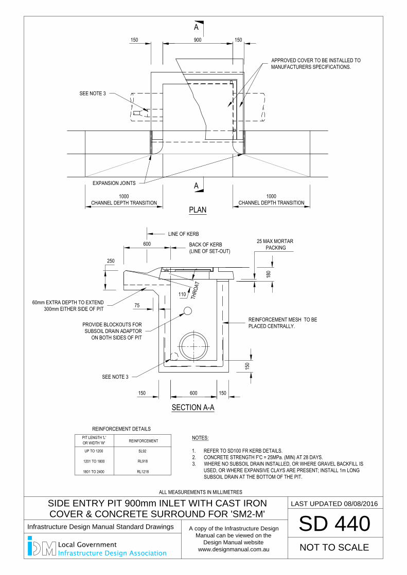
SIDE ENTRY PIT 900mm INLET WITH CAST IRON
COVER & CONCRETE SURROUND FOR 'SM2-M'
SD 440
PLAN
75
150 900 150
1000CHANNEL DEPTH TRANSITION
1000CHANNEL DEPTH TRANSITION
600
25018
0
150
150 600 150
110
REINFORCEMENT
REINFORCEMENT DETAILS
UP TO 1200
1201 TO 1800
1801 TO 2400
OR WIDTH 'W'PIT LENGTH 'L'
SL92
RL1218
RL918
THRO
AT
BACK OF KERB(LINE OF SET-OUT)
SECTION A-A
A
A
LAST UPDATED 08/08/2016
25 MAX MORTAR PACKING
NOTES:
1. REFER TO SD100 FR KERB DETAILS.2. CONCRETE STRENGTH F'C = 25MPa. (MIN) AT 28 DAYS.3. WHERE NO SUBSOIL DRAIN INSTALLED, OR WHERE GRAVEL BACKFILL IS
USED, OR WHERE EXPANSIVE CLAYS ARE PRESENT; INSTALL 1m LONGSUBSOIL DRAIN AT THE BOTTOM OF THE PIT.
NOT TO SCALE
REINFORCEMENT MESH TO BEPLACED CENTRALLY.
APPROVED COVER TO BE INSTALLED TOMANUFACTURERS SPECIFICATIONS.
60mm EXTRA DEPTH TO EXTEND300mm EITHER SIDE OF PIT
SEE NOTE 3
PROVIDE BLOCKOUTS FORSUBSOIL DRAIN ADAPTOR
ON BOTH SIDES OF PIT
SEE NOTE 3
LINE OF KERB
EXPANSION JOINTS
ALL MEASUREMENTS IN MILLIMETRES
Infrastructure Design Manual Standard Drawings
A copy of the Infrastructure Design
Manual can be viewed on the
Design Manual website
www.designmanual.com.au
Local GovernmentInfrastructure Design Association
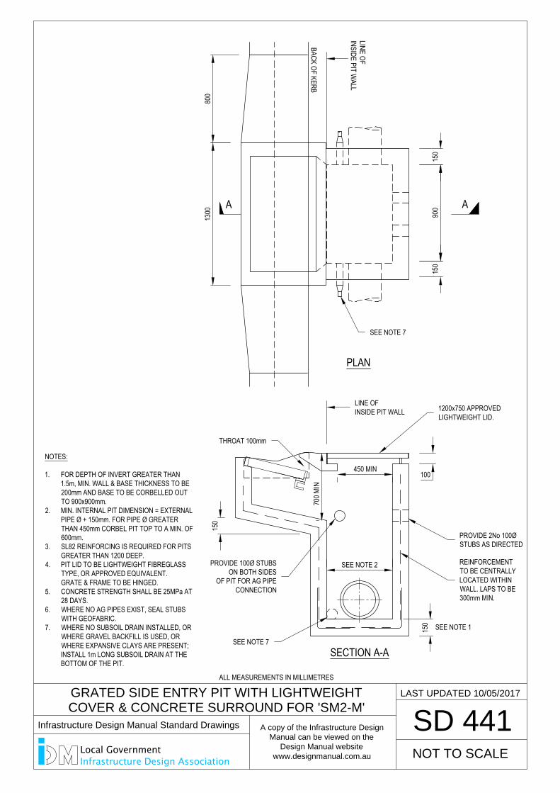
GRATED SIDE ENTRY PIT WITH LIGHTWEIGHT
COVER & CONCRETE SURROUND FOR 'SM2-M'
SD 441
PLAN
LAST UPDATED 10/05/2017
NOT TO SCALE
100450 MIN
700 M
IN
150
SEE NOTE 2
SECTION A-A
150 SEE NOTE 1
NOTES:
1. FOR DEPTH OF INVERT GREATER THAN1.5m, MIN. WALL & BASE THICKNESS TO BE200mm AND BASE TO BE CORBELLED OUTTO 900x900mm.
2. MIN. INTERNAL PIT DIMENSION = EXTERNALPIPE Ø + 150mm. FOR PIPE Ø GREATERTHAN 450mm CORBEL PIT TOP TO A MIN. OF600mm.
3. SL82 REINFORCING IS REQUIRED FOR PITSGREATER THAN 1200 DEEP.
4. PIT LID TO BE LIGHTWEIGHT FIBREGLASSTYPE, OR APPROVED EQUIVALENT.GRATE & FRAME TO BE HINGED.
5. CONCRETE STRENGTH SHALL BE 25MPa AT28 DAYS.
6. WHERE NO AG PIPES EXIST, SEAL STUBSWITH GEOFABRIC.
7. WHERE NO SUBSOIL DRAIN INSTALLED, ORWHERE GRAVEL BACKFILL IS USED, ORWHERE EXPANSIVE CLAYS ARE PRESENT;INSTALL 1m LONG SUBSOIL DRAIN AT THEBOTTOM OF THE PIT.
AA
900
150
1300
800
LINE OFINSIDE PIT W
ALL
BACK OF KERB
150
LINE OFINSIDE PIT WALL
SEE NOTE 7
PROVIDE 100Ø STUBSON BOTH SIDES
OF PIT FOR AG PIPECONNECTION
THROAT 100mm
1200x750 APPROVEDLIGHTWEIGHT LID.
PROVIDE 2No 100ØSTUBS AS DIRECTED
REINFORCEMENTTO BE CENTRALLYLOCATED WITHINWALL. LAPS TO BE300mm MIN.
SEE NOTE 7
ALL MEASUREMENTS IN MILLIMETRES
Infrastructure Design Manual Standard Drawings
A copy of the Infrastructure Design
Manual can be viewed on the
Design Manual website
www.designmanual.com.au
Local GovernmentInfrastructure Design Association
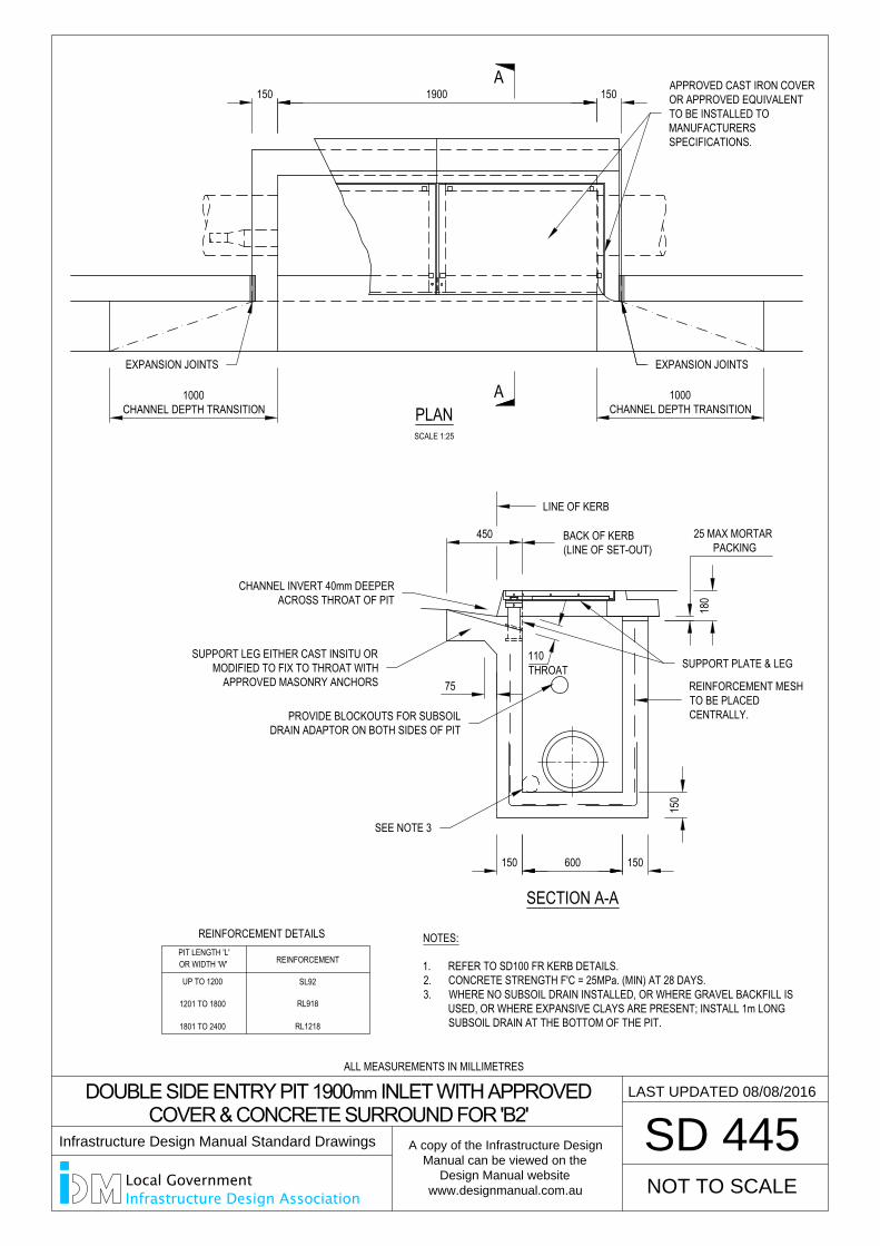
75
SCALE 1:25
PLAN
150 1900 150
1000CHANNEL DEPTH TRANSITION
450
180
150
150 600 150
1000CHANNEL DEPTH TRANSITION
DOUBLE SIDE ENTRY PIT 1900 mm INLET WITH APPROVED
COVER & CONCRETE SURROUND FOR 'B2'
SD 445
REINFORCEMENT
REINFORCEMENT DETAILS
UP TO 1200
1201 TO 1800
1801 TO 2400
OR WIDTH 'W'PIT LENGTH 'L'
SL92
RL1218
RL918
SECTION A-A
A
A
BACK OF KERB(LINE OF SET-OUT)
110THROAT
NOTES:
1. REFER TO SD100 FR KERB DETAILS.2. CONCRETE STRENGTH F'C = 25MPa. (MIN) AT 28 DAYS.3. WHERE NO SUBSOIL DRAIN INSTALLED, OR WHERE GRAVEL BACKFILL IS
USED, OR WHERE EXPANSIVE CLAYS ARE PRESENT; INSTALL 1m LONGSUBSOIL DRAIN AT THE BOTTOM OF THE PIT.
LAST UPDATED 08/08/2016
25 MAX MORTAR PACKING
NOT TO SCALE
REINFORCEMENT MESHTO BE PLACEDCENTRALLY.
APPROVED CAST IRON COVEROR APPROVED EQUIVALENTTO BE INSTALLED TOMANUFACTURERSSPECIFICATIONS.
PROVIDE BLOCKOUTS FOR SUBSOILDRAIN ADAPTOR ON BOTH SIDES OF PIT
SEE NOTE 3
LINE OF KERB
EXPANSION JOINTS EXPANSION JOINTS
SUPPORT PLATE & LEGSUPPORT LEG EITHER CAST INSITU OR
MODIFIED TO FIX TO THROAT WITHAPPROVED MASONRY ANCHORS
CHANNEL INVERT 40mm DEEPERACROSS THROAT OF PIT
ALL MEASUREMENTS IN MILLIMETRES
Infrastructure Design Manual Standard Drawings
A copy of the Infrastructure Design
Manual can be viewed on the
Design Manual website
www.designmanual.com.au
Local GovernmentInfrastructure Design Association
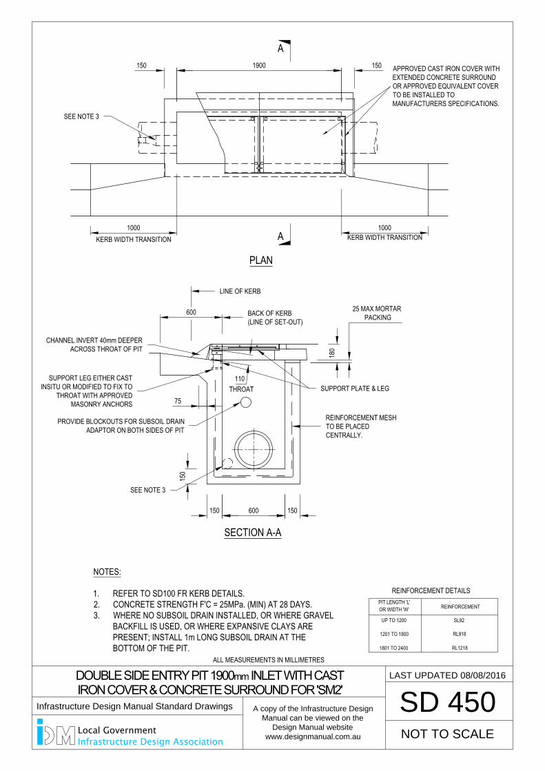
KERB WIDTH TRANSITION
600
75
PLAN
150 1900 150
1000 1000KERB WIDTH TRANSITION
150 600 150
150
25 MAX MORTAR PACKING
180
110
DOUBLE SIDE ENTRY PIT 1900 mm INLET WITH CAST
IRON COVER & CONCRETE SURROUND FOR 'SM2'
SD 450
REINFORCEMENT
REINFORCEMENT DETAILS
UP TO 1200
1201 TO 1800
1801 TO 2400
OR WIDTH 'W'PIT LENGTH 'L'
SL92
RL1218
RL918
NOT TO SCALE
SECTION A-A
A
A
THROAT
BACK OF KERB(LINE OF SET-OUT)
APPROVED CAST IRON COVER WITHEXTENDED CONCRETE SURROUNDOR APPROVED EQUIVALENT COVERTO BE INSTALLED TOMANUFACTURERS SPECIFICATIONS.
LAST UPDATED 08/08/2016
NOTES:
1. REFER TO SD100 FR KERB DETAILS.2. CONCRETE STRENGTH F'C = 25MPa. (MIN) AT 28 DAYS.3. WHERE NO SUBSOIL DRAIN INSTALLED, OR WHERE GRAVEL
BACKFILL IS USED, OR WHERE EXPANSIVE CLAYS AREPRESENT; INSTALL 1m LONG SUBSOIL DRAIN AT THEBOTTOM OF THE PIT.
REINFORCEMENT MESHTO BE PLACEDCENTRALLY.
SEE NOTE 3
LINE OF KERB
SUPPORT PLATE & LEGSUPPORT LEG EITHER CAST
INSITU OR MODIFIED TO FIX TOTHROAT WITH APPROVED
MASONRY ANCHORS
CHANNEL INVERT 40mm DEEPERACROSS THROAT OF PIT
PROVIDE BLOCKOUTS FOR SUBSOIL DRAINADAPTOR ON BOTH SIDES OF PIT
SEE NOTE 3
ALL MEASUREMENTS IN MILLIMETRES
Infrastructure Design Manual Standard Drawings
A copy of the Infrastructure Design
Manual can be viewed on the
Design Manual website
www.designmanual.com.au
Local GovernmentInfrastructure Design Association
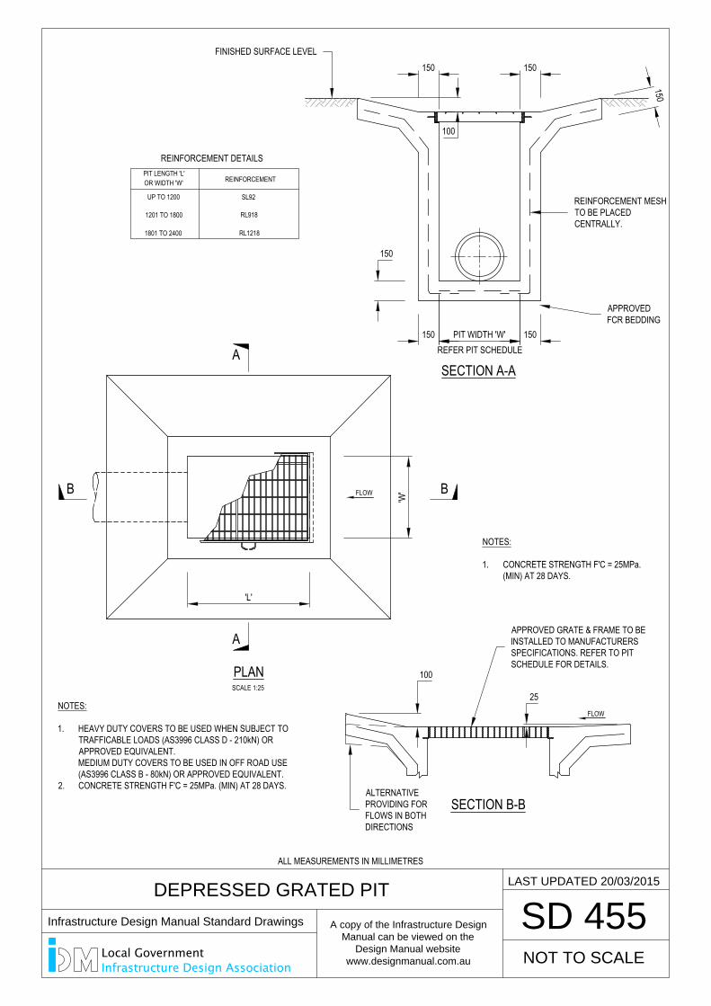
FLOW
SCALE 1:25
150
150PIT WIDTH 'W'150REFER PIT SCHEDULE
FLOW
25
150 150
100
150
100
DEPRESSED GRATED PIT
SD 455
REINFORCEMENT
REINFORCEMENT DETAILS
UP TO 1200
1201 TO 1800
1801 TO 2400
OR WIDTH 'W'PIT LENGTH 'L'
SL92
RL1218
RL918
PLAN
A
A
B B
SECTION B-B
SECTION A-A
LAST UPDATED 20/03/2015
NOTES:
1. CONCRETE STRENGTH F'C = 25MPa.(MIN) AT 28 DAYS.
'W'
'L'
NOTES:
1. HEAVY DUTY COVERS TO BE USED WHEN SUBJECT TOTRAFFICABLE LOADS (AS3996 CLASS D - 210kN) ORAPPROVED EQUIVALENT.MEDIUM DUTY COVERS TO BE USED IN OFF ROAD USE(AS3996 CLASS B - 80kN) OR APPROVED EQUIVALENT.
2. CONCRETE STRENGTH F'C = 25MPa. (MIN) AT 28 DAYS.
NOT TO SCALE
REINFORCEMENT MESHTO BE PLACEDCENTRALLY.
FINISHED SURFACE LEVEL
APPROVEDFCR BEDDING
APPROVED GRATE & FRAME TO BEINSTALLED TO MANUFACTURERSSPECIFICATIONS. REFER TO PITSCHEDULE FOR DETAILS.
ALTERNATIVEPROVIDING FORFLOWS IN BOTHDIRECTIONS
ALL MEASUREMENTS IN MILLIMETRES
Infrastructure Design Manual Standard Drawings
A copy of the Infrastructure Design
Manual can be viewed on the
Design Manual website
www.designmanual.com.au
Local GovernmentInfrastructure Design Association
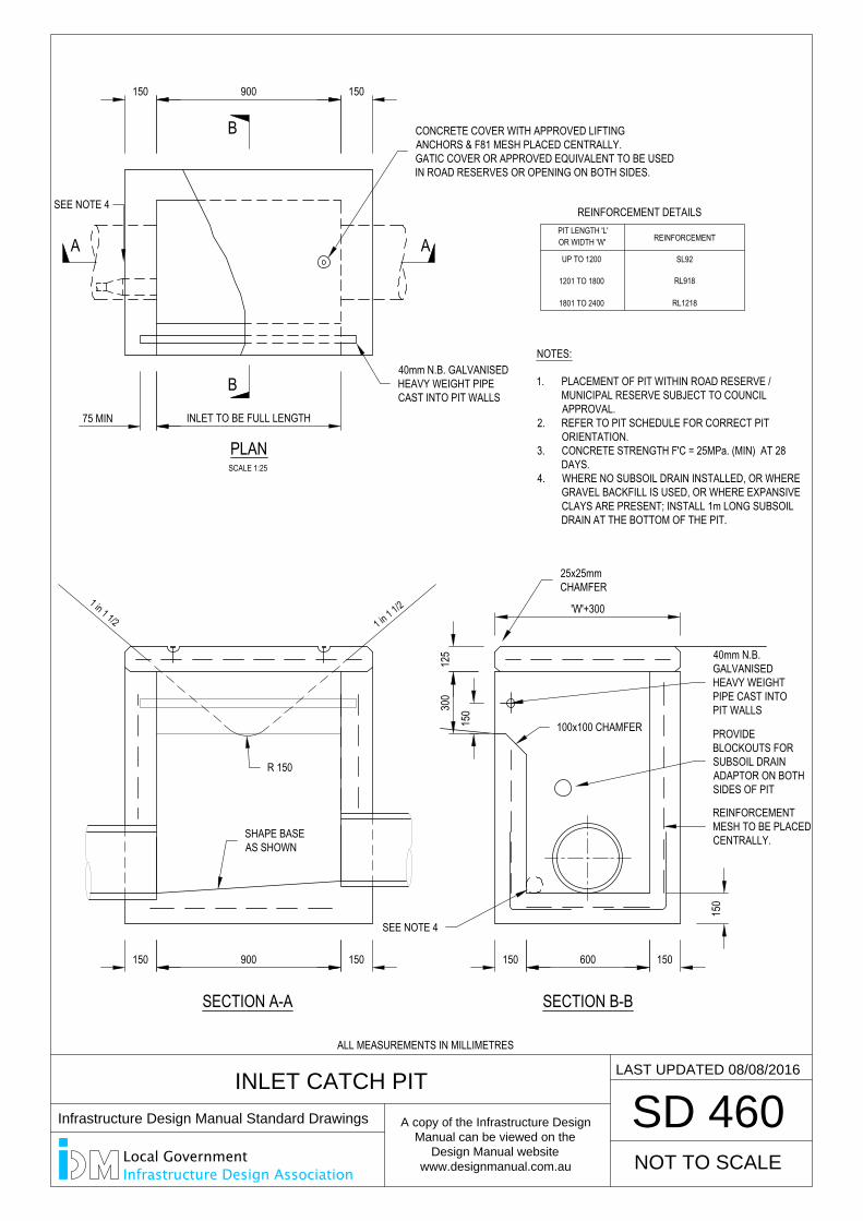
'W'+300
300
125
150
150
150 600 150
INLET TO BE FULL LENGTH75 MIN
150 900 150
INLET CATCH PIT
SD 460
REINFORCEMENT
REINFORCEMENT DETAILS
UP TO 1200
1201 TO 1800
1801 TO 2400
OR WIDTH 'W'PIT LENGTH 'L'
SL92
RL1218
RL918
B
B
SECTION B-B
SCALE 1:25
PLAN
NOTES:
1. PLACEMENT OF PIT WITHIN ROAD RESERVE /MUNICIPAL RESERVE SUBJECT TO COUNCILAPPROVAL.
2. REFER TO PIT SCHEDULE FOR CORRECT PITORIENTATION.
3. CONCRETE STRENGTH F'C = 25MPa. (MIN) AT 28DAYS.
4. WHERE NO SUBSOIL DRAIN INSTALLED, OR WHEREGRAVEL BACKFILL IS USED, OR WHERE EXPANSIVECLAYS ARE PRESENT; INSTALL 1m LONG SUBSOILDRAIN AT THE BOTTOM OF THE PIT.
LAST UPDATED 08/08/2016
NOT TO SCALE
A A
150 900 150
SECTION A-A
1 in 1 1/21 in 1 1/2
40mm N.B. GALVANISEDHEAVY WEIGHT PIPECAST INTO PIT WALLS
SEE NOTE 4
25x25mmCHAMFER
40mm N.B.GALVANISEDHEAVY WEIGHTPIPE CAST INTOPIT WALLS
PROVIDEBLOCKOUTS FORSUBSOIL DRAINADAPTOR ON BOTHSIDES OF PIT
REINFORCEMENTMESH TO BE PLACEDCENTRALLY.SHAPE BASE
AS SHOWN
R 150
100x100 CHAMFER
SEE NOTE 4
CONCRETE COVER WITH APPROVED LIFTINGANCHORS & F81 MESH PLACED CENTRALLY.GATIC COVER OR APPROVED EQUIVALENT TO BE USEDIN ROAD RESERVES OR OPENING ON BOTH SIDES.
ALL MEASUREMENTS IN MILLIMETRES
Infrastructure Design Manual Standard Drawings
A copy of the Infrastructure Design
Manual can be viewed on the
Design Manual website
www.designmanual.com.au
Local GovernmentInfrastructure Design Association
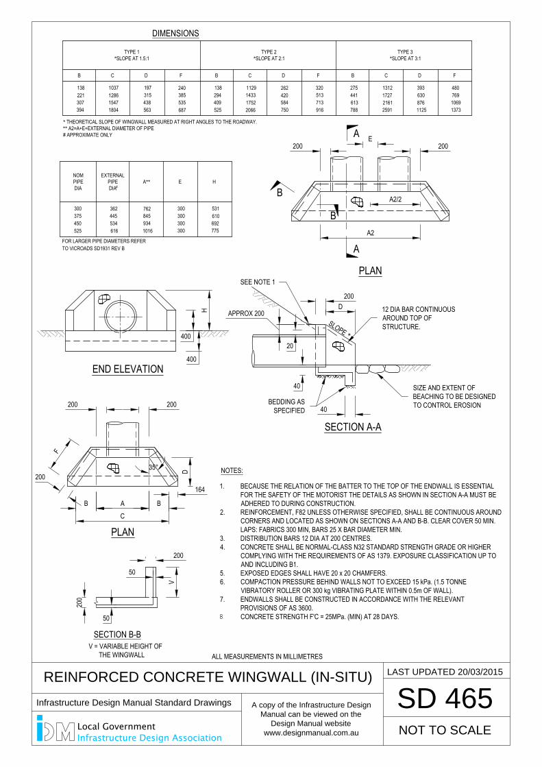
REINFORCED CONCRETE WINGWALL (IN-SITU)
SD 465
SECTION A-A
NOTES:
END ELEVATION
SECTION B-B
PLAN
PLAN
DIMENSIONS
NOMPIPEDIA
EXTERNALPIPEDIA
A**
#E H
TYPE 1*SLOPE AT 1.5:1
300375450525 616
534445362
1016
762845934
300
300300300
775
531610692
394
138221307
1804
103712861547
563
197315438
687
240385535
B C D F
* THEORETICAL SLOPE OF WINGWALL MEASURED AT RIGHT ANGLES TO THE ROADWAY.** A2=A+E+EXTERNAL DIAMETER OF PIPE# APPROXIMATE ONLY
294409525
B
138143317522066
1129
C
420584750
D
262513713916
F
320
TYPE 2*SLOPE AT 2:1
C
1312
259121611727
275
788613441
B
630
1125876
393
D
769
13731069
480
F
TYPE 3*SLOPE AT 3:1
200
50
200
50
V
200200E
A2/2
A2
200200
D
F
C
B A B
164
H
400
400
D200
APPROX 200
40
20
40
35°
1. BECAUSE THE RELATION OF THE BATTER TO THE TOP OF THE ENDWALL IS ESSENTIALFOR THE SAFETY OF THE MOTORIST THE DETAILS AS SHOWN IN SECTION A-A MUST BEADHERED TO DURING CONSTRUCTION.
2. REINFORCEMENT, F82 UNLESS OTHERWISE SPECIFIED, SHALL BE CONTINUOUS AROUNDCORNERS AND LOCATED AS SHOWN ON SECTIONS A-A AND B-B. CLEAR COVER 50 MIN.LAPS: FABRICS 300 MIN, BARS 25 X BAR DIAMETER MIN.
3. DISTRIBUTION BARS 12 DIA AT 200 CENTRES.4. CONCRETE SHALL BE NORMAL-CLASS N32 STANDARD STRENGTH GRADE OR HIGHER
COMPLYING WITH THE REQUIREMENTS OF AS 1379. EXPOSURE CLASSIFICATION UP TOAND INCLUDING B1.
5. EXPOSED EDGES SHALL HAVE 20 x 20 CHAMFERS.6. COMPACTION PRESSURE BEHIND WALLS NOT TO EXCEED 15 kPa. (1.5 TONNE
VIBRATORY ROLLER OR 300 kg VIBRATING PLATE WITHIN 0.5m OF WALL).7. ENDWALLS SHALL BE CONSTRUCTED IN ACCORDANCE WITH THE RELEVANT
PROVISIONS OF AS 3600.CONCRETE STRENGTH F'C = 25MPa. (MIN) AT 28 DAYS.
FOR LARGER PIPE DIAMETERS REFERTO VICROADS SD1931 REV B
SLOPE
*
A
A
200
B
B
NOT TO SCALE
LAST UPDATED 20/03/2015
V = VARIABLE HEIGHT OFTHE WINGWALL
SIZE AND EXTENT OFBEACHING TO BE DESIGNEDTO CONTROL EROSION
12 DIA BAR CONTINUOUSAROUND TOP OFSTRUCTURE.
SEE NOTE 1
BEDDING ASSPECIFIED
ALL MEASUREMENTS IN MILLIMETRES
Infrastructure Design Manual Standard Drawings
A copy of the Infrastructure Design
Manual can be viewed on the
Design Manual website
www.designmanual.com.au
Local GovernmentInfrastructure Design Association
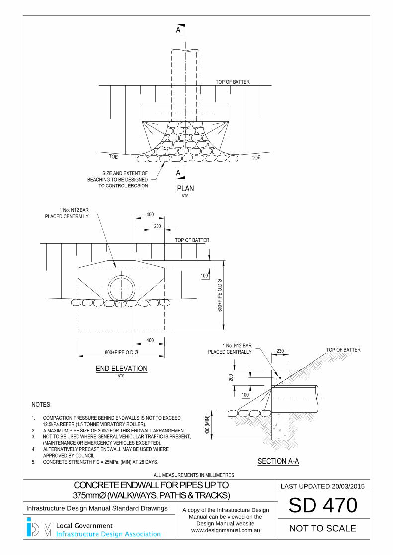
NTS
TOE
NTSPLAN
TOP OF BATTER
TOE
END ELEVATION
230
100
200
400 (
MIN)
400
200
100
600+
PIPE
O.D
.Ø
800+PIPE O.D.Ø
400
SD 470
A
A
SECTION A-A
NOTES:
1. COMPACTION PRESSURE BEHIND ENDWALLS IS NOT TO EXCEED12.5kPa.REFER (1.5 TONNE VIBRATORY ROLLER).
2. A MAXIMUM PIPE SIZE OF 300Ø FOR THIS ENDWALL ARRANGEMENT.3. NOT TO BE USED WHERE GENERAL VEHICULAR TRAFFIC IS PRESENT,
(MAINTENANCE OR EMERGENCY VEHICLES EXCEPTED).4. ALTERNATIVELY PRECAST ENDWALL MAY BE USED WHERE
APPROVED BY COUNCIL.5. CONCRETE STRENGTH F'C = 25MPa. (MIN) AT 28 DAYS.
NOT TO SCALE
LAST UPDATED 20/03/2015CONCRETE ENDWALL FOR PIPES UP TO
375mmØ (WALKWAYS, PATHS & TRACKS)
SIZE AND EXTENT OFBEACHING TO BE DESIGNED
TO CONTROL EROSION
1 No. N12 BARPLACED CENTRALLY
1 No. N12 BARPLACED CENTRALLY
TOP OF BATTER
TOP OF BATTER
ALL MEASUREMENTS IN MILLIMETRES
Infrastructure Design Manual Standard Drawings
A copy of the Infrastructure Design
Manual can be viewed on the
Design Manual website
www.designmanual.com.au
Local GovernmentInfrastructure Design Association
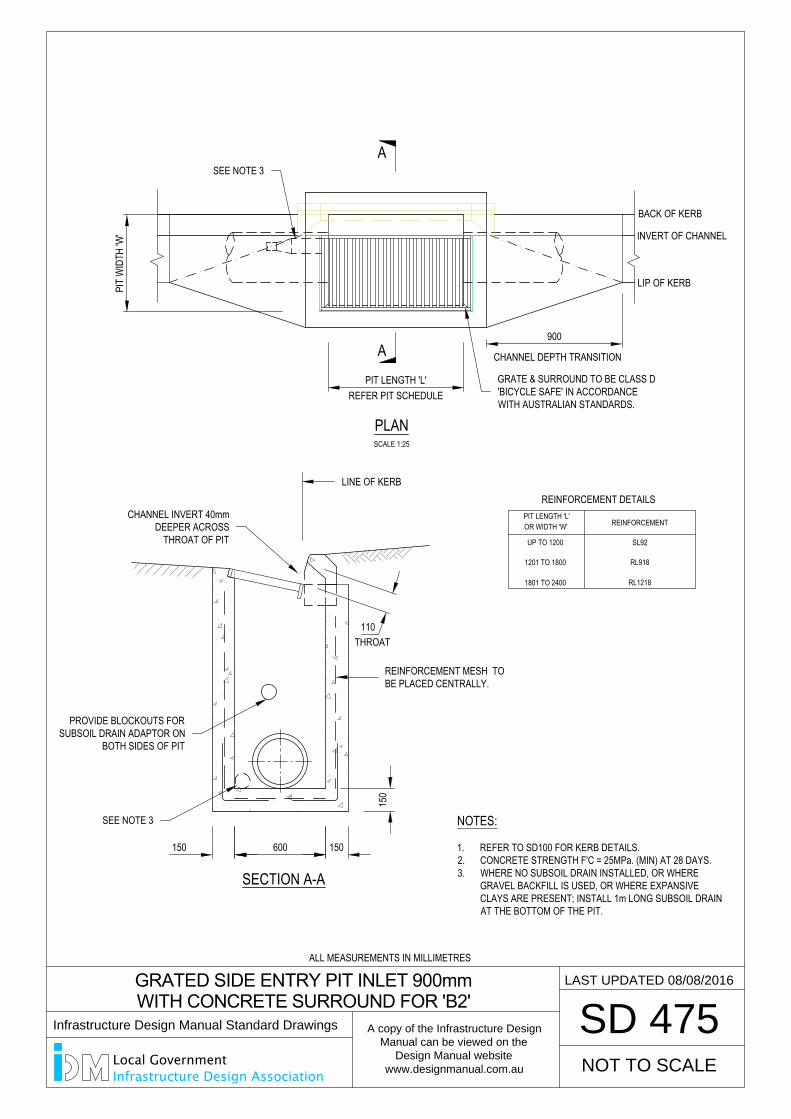
BACK OF KERB
INVERT OF CHANNEL
LIP OF KERB
150 600 150
150
SCALE 1:25
PLAN
900
SD 475
CHANNEL DEPTH TRANSITION
GRATED SIDE ENTRY PIT INLET 900mm
WITH CONCRETE SURROUND FOR 'B2'
REINFORCEMENT
REINFORCEMENT DETAILS
UP TO 1200
1201 TO 1800
1801 TO 2400
OR WIDTH 'W'PIT LENGTH 'L'
SL92
RL1218
RL918
A
A
SECTION A-A
110THROAT
NOT TO SCALE
LAST UPDATED 08/08/2016
REFER PIT SCHEDULEPIT LENGTH 'L'
PIT
WID
TH 'W
'
NOTES:
1. REFER TO SD100 FOR KERB DETAILS.2. CONCRETE STRENGTH F'C = 25MPa. (MIN) AT 28 DAYS.3. WHERE NO SUBSOIL DRAIN INSTALLED, OR WHERE
GRAVEL BACKFILL IS USED, OR WHERE EXPANSIVECLAYS ARE PRESENT; INSTALL 1m LONG SUBSOIL DRAINAT THE BOTTOM OF THE PIT.
REINFORCEMENT MESH TOBE PLACED CENTRALLY.
SEE NOTE 3
CHANNEL INVERT 40mmDEEPER ACROSS
THROAT OF PIT
PROVIDE BLOCKOUTS FORSUBSOIL DRAIN ADAPTOR ON
BOTH SIDES OF PIT
SEE NOTE 3
GRATE & SURROUND TO BE CLASS D'BICYCLE SAFE' IN ACCORDANCEWITH AUSTRALIAN STANDARDS.
LINE OF KERB
ALL MEASUREMENTS IN MILLIMETRES
Infrastructure Design Manual Standard Drawings
A copy of the Infrastructure Design
Manual can be viewed on the
Design Manual website
www.designmanual.com.au
Local GovernmentInfrastructure Design Association
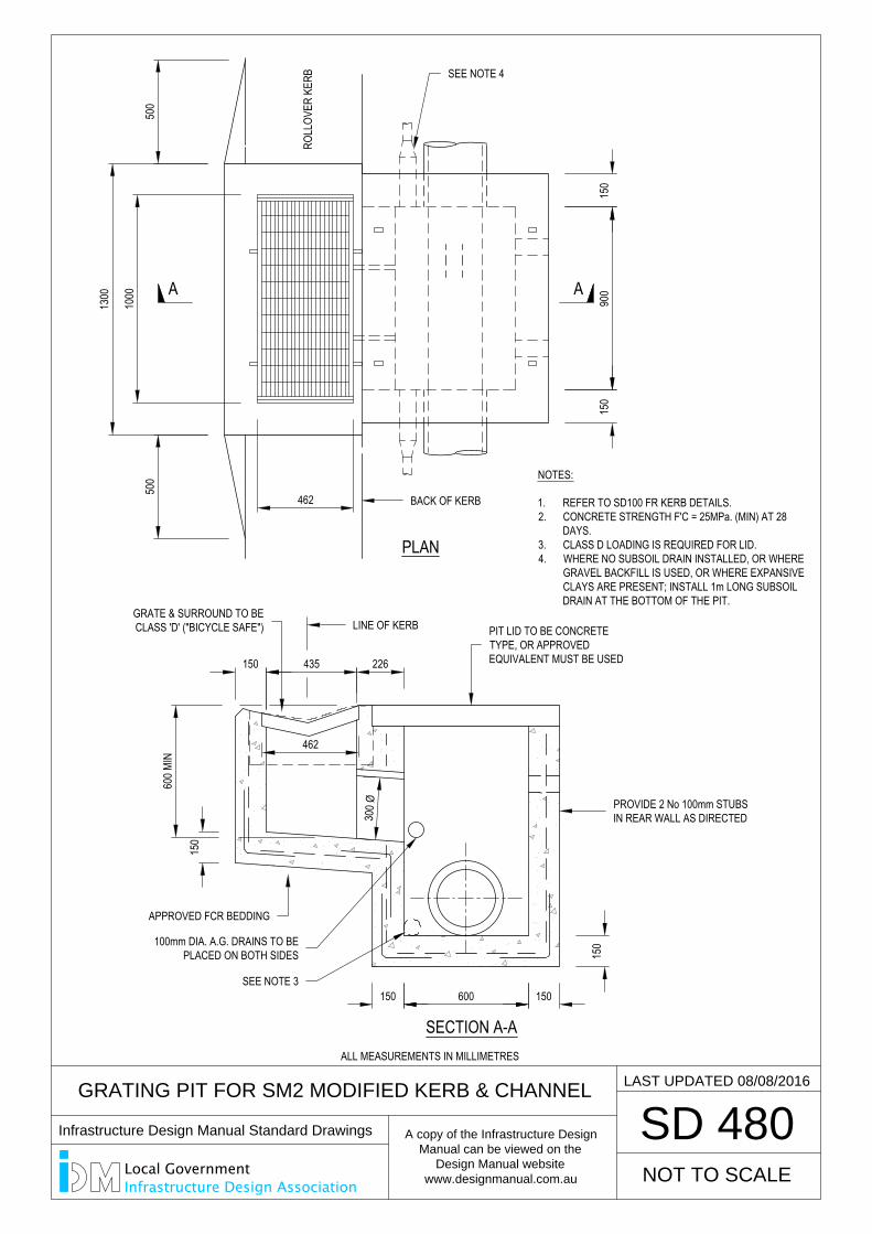
GRATING PIT FOR SM2 MODIFIED KERB & CHANNEL
SD 480
SECTION A-A
PLAN
150 600 150
150
300 Ø
150
600 M
IN
150 435
462
226
462
1300
1000
500
500
ROLL
OVER
KER
B
150
900
150
A A
NOT TO SCALE
LAST UPDATED 08/08/2016
NOTES:
1. REFER TO SD100 FR KERB DETAILS.2. CONCRETE STRENGTH F'C = 25MPa. (MIN) AT 28
DAYS.3. CLASS D LOADING IS REQUIRED FOR LID.4. WHERE NO SUBSOIL DRAIN INSTALLED, OR WHERE
GRAVEL BACKFILL IS USED, OR WHERE EXPANSIVECLAYS ARE PRESENT; INSTALL 1m LONG SUBSOILDRAIN AT THE BOTTOM OF THE PIT.
PROVIDE 2 No 100mm STUBSIN REAR WALL AS DIRECTED
GRATE & SURROUND TO BECLASS 'D' ("BICYCLE SAFE") PIT LID TO BE CONCRETE
TYPE, OR APPROVEDEQUIVALENT MUST BE USED
LINE OF KERB
APPROVED FCR BEDDING
100mm DIA. A.G. DRAINS TO BEPLACED ON BOTH SIDES
SEE NOTE 3
SEE NOTE 4
BACK OF KERB
ALL MEASUREMENTS IN MILLIMETRES
Infrastructure Design Manual Standard Drawings
A copy of the Infrastructure Design
Manual can be viewed on the
Design Manual website
www.designmanual.com.au
Local GovernmentInfrastructure Design Association
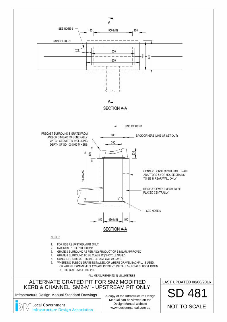
ALTERNATE GRATED PIT FOR SM2 MODIFIED
KERB & CHANNEL 'SM2-M' - UPSTREAM PIT ONLY
SD 481
NOT TO SCALE
LAST UPDATED 08/08/2016
A
A
450 MIN150 150
600 BACK OF KERB (LINE OF SET-OUT)
SECTION A-A
190 235
900 MIN150
BACK OF KERB
1230
1000
390
600
520
SECTION A-A
NOTES:
1. FOR USE AS UPSTREAM PIT ONLY2. MAXIMUM PIT DEPTH 1000mm3. GRATE & SURROUND AS PER ASQ PRODUCT OR SIMILAR APPROVED4. GRATE & SURROUND TO BE CLASS 'D' ("BICYCLE SAFE")5. CONCRETE STRENGTH SHALL BE 25MPa AT 28 DAYS.6. WHERE NO SUBSOIL DRAIN INSTALLED, OR WHERE GRAVEL BACKFILL IS USED,
OR WHERE EXPANSIVE CLAYS ARE PRESENT; INSTALL 1m LONG SUBSOIL DRAINAT THE BOTTOM OF THE PIT.
150
600 S
M2-M
KER
B
1000
MAX CONNECTIONS FOR SUBSOIL DRAIN
ADAPTORS & \ OR HOUSE DRAINSTO BE IN REAR WALL ONLY
PRECAST SURROUND & GRATE FROMASQ OR SIMILAR TO GENERALLY
MATCH GEOMETRY INCLUDINGDEPTH OF SD 100 SM2-M KERB
LINE OF KERB
SEE NOTE 6
REINFORCEMENT MESH TO BEPLACED CENTRALLY
SEE NOTE 6
ALL MEASUREMENTS IN MILLIMETRES
Infrastructure Design Manual Standard Drawings
A copy of the Infrastructure Design
Manual can be viewed on the
Design Manual website
www.designmanual.com.au
Local GovernmentInfrastructure Design Association
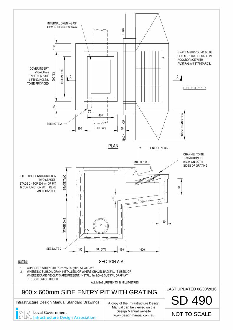
150 150600 ('W')
50
600
150
STAG
E ON
EST
AGE
TWO
150
900 (
'L')
150
300
600m
m TR
ANSI
TION
150 600 ('W') 150
INSE
RT T
30
COVER INSERT730x480mm
TAPER ON SIDELIFTING HOLE/S
TO BE PROVIDED
NOTES:
480
BACK
OFKE
RB
PLAN
SECTION A-A
SD 490
900 x 600mm SIDE ENTRY PIT WITH GRATING
PIT TO BE CONSTRUCTED INTWO STAGES.
STAGE 2 - TOP 500mm OF PITIN CONJUNCTION WITH KERB
AND CHANNEL.
110 THROAT
NOT TO SCALE
LAST UPDATED 08/08/2016
SEE NOTE 2
1. CONCRETE STRENGTH F'C = 25MPa. (MIN) AT 28 DAYS2. WHERE NO SUBSOIL DRAIN INSTALLED, OR WHERE GRAVEL BACKFILL IS USED, OR
WHERE EXPANSIVE CLAYS ARE PRESENT; INSTALL 1m LONG SUBSOIL DRAIN ATTHE BOTTOM OF THE PIT.
CHANNEL TO BETRANSITIONED0.60m ON BOTHSIDES OF GRATING
LINE OF KERB
GRATE & SURROUND TO BECLASS D 'BICYCLE SAFE' INACCORDANCE WITHAUSTRALIAN STANDARDS.
SEE NOTE 2
INTERNAL OPENING OFCOVER 600mm x 350mm
ALL MEASUREMENTS IN MILLIMETRES
Infrastructure Design Manual Standard Drawings
A copy of the Infrastructure Design
Manual can be viewed on the
Design Manual website
www.designmanual.com.au
Local GovernmentInfrastructure Design Association
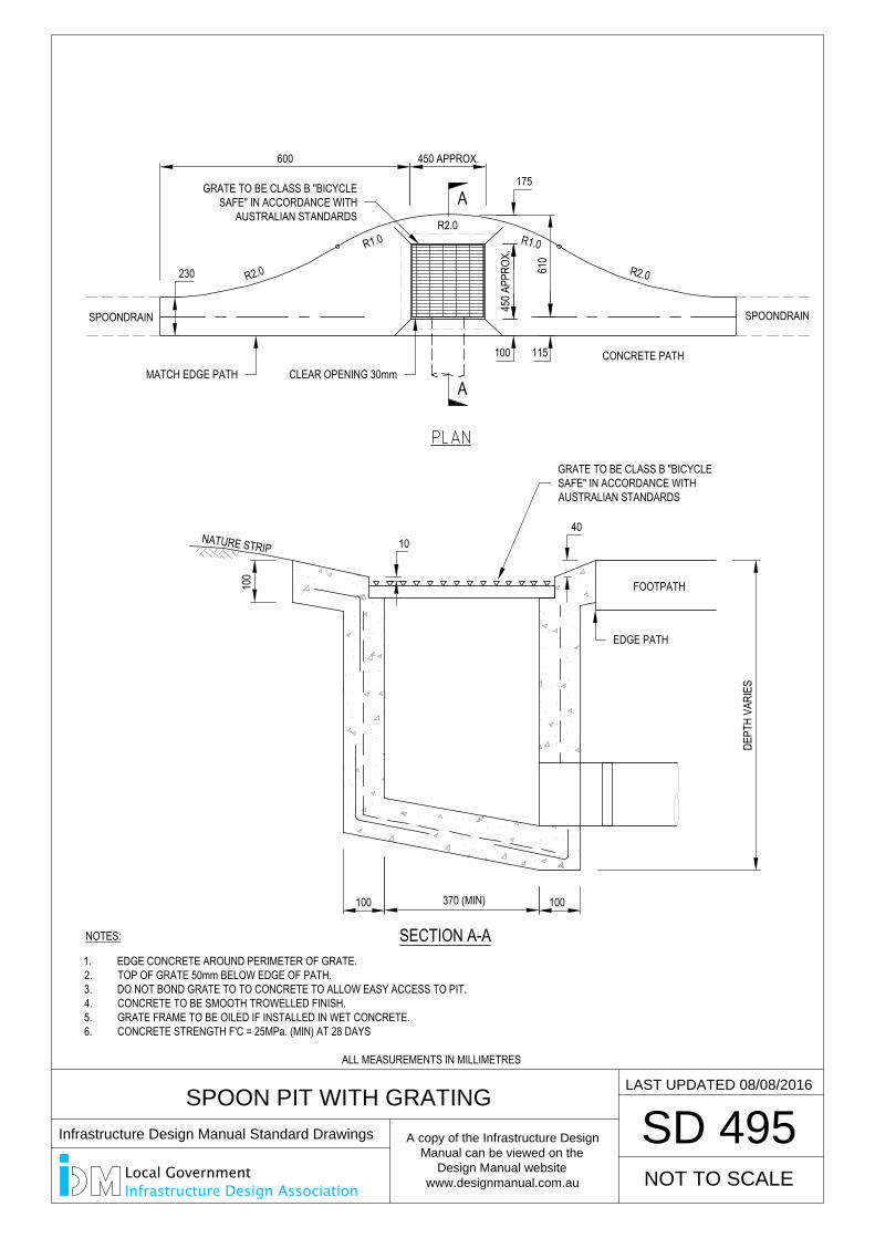
SPOON PIT WITH GRATING
SD 495
450 A
PPRO
X.
610
SPOONDRAIN
230
600 450 APPROX.
R2.0 R2.0
R2.0
CONCRETE PATH
100
100370 (MIN)100
FOOTPATH
NATURE STRIP
40
A
A
NOT TO SCALE
DEPT
H VA
RIES
SECTION A-A
R1.0 R1.0
100
175
10
NOTES:
1. EDGE CONCRETE AROUND PERIMETER OF GRATE.2. TOP OF GRATE 50mm BELOW EDGE OF PATH.3. DO NOT BOND GRATE TO TO CONCRETE TO ALLOW EASY ACCESS TO PIT.4. CONCRETE TO BE SMOOTH TROWELLED FINISH.5. GRATE FRAME TO BE OILED IF INSTALLED IN WET CONCRETE.6. CONCRETE STRENGTH F'C = 25MPa. (MIN) AT 28 DAYS
LAST UPDATED 08/08/2016
115
SPOONDRAIN
EDGE PATH
GRATE TO BE CLASS B "BICYCLESAFE" IN ACCORDANCE WITHAUSTRALIAN STANDARDS
GRATE TO BE CLASS B "BICYCLESAFE" IN ACCORDANCE WITH
AUSTRALIAN STANDARDS
MATCH EDGE PATH CLEAR OPENING 30mm
ALL MEASUREMENTS IN MILLIMETRES
Infrastructure Design Manual Standard Drawings
A copy of the Infrastructure Design
Manual can be viewed on the
Design Manual website
www.designmanual.com.au
Local GovernmentInfrastructure Design Association
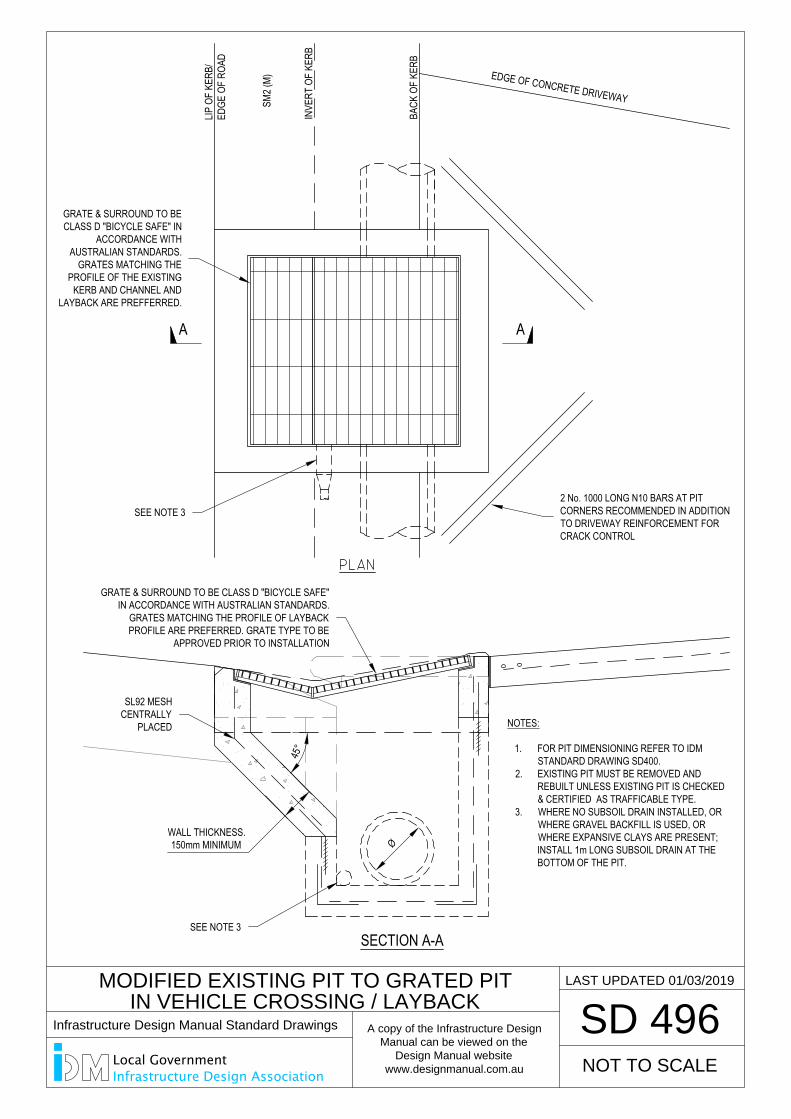
MODIFIED EXISTING PIT TO GRATED PIT
IN VEHICLE CROSSING / LAYBACK
SD 496
NOT TO SCALE
LAST UPDATED 01/03/2019
45°
WALL THICKNESS.150mm MINIMUM
NOTES:
1. FOR PIT DIMENSIONING REFER TO IDMSTANDARD DRAWING SD400.
2. EXISTING PIT MUST BE REMOVED ANDREBUILT UNLESS EXISTING PIT IS CHECKED& CERTIFIED AS TRAFFICABLE TYPE.
3. WHERE NO SUBSOIL DRAIN INSTALLED, ORWHERE GRAVEL BACKFILL IS USED, ORWHERE EXPANSIVE CLAYS ARE PRESENT;INSTALL 1m LONG SUBSOIL DRAIN AT THEBOTTOM OF THE PIT.
Ø
BACK
OF
KERB
LIP O
F KE
RB/
EDGE
OF
ROAD
SECTION A-A
A A
SM2 (
M) EDGE OF CONCRETE DRIVEWAY
INVE
RT O
F KE
RB
2 No. 1000 LONG N10 BARS AT PITCORNERS RECOMMENDED IN ADDITIONTO DRIVEWAY REINFORCEMENT FORCRACK CONTROL
GRATE & SURROUND TO BE CLASS D "BICYCLE SAFE"IN ACCORDANCE WITH AUSTRALIAN STANDARDS.
GRATES MATCHING THE PROFILE OF LAYBACKPROFILE ARE PREFERRED. GRATE TYPE TO BE
APPROVED PRIOR TO INSTALLATION
SEE NOTE 3
SL92 MESHCENTRALLY
PLACED
SEE NOTE 3
GRATE & SURROUND TO BECLASS D "BICYCLE SAFE" IN
ACCORDANCE WITHAUSTRALIAN STANDARDS.
GRATES MATCHING THEPROFILE OF THE EXISTING
KERB AND CHANNEL ANDLAYBACK ARE PREFFERRED.
Infrastructure Design Manual Standard Drawings
A copy of the Infrastructure Design
Manual can be viewed on the
Design Manual website
www.designmanual.com.au
Local GovernmentInfrastructure Design Association
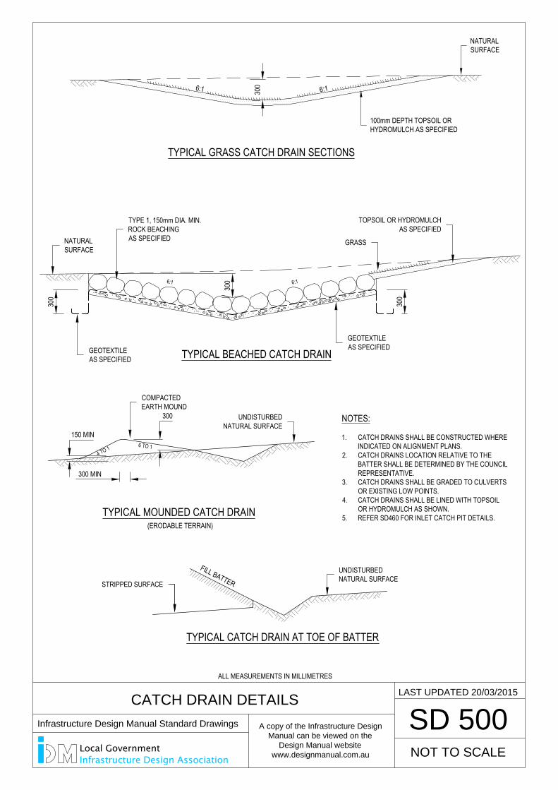
300
300
TYPICAL BEACHED CATCH DRAIN
6:1 6:1
300
300
TYPICAL GRASS CATCH DRAIN SECTIONS
6:1 6:1
TYPICAL CATCH DRAIN AT TOE OF BATTER
TYPICAL MOUNDED CATCH DRAIN(ERODABLE TERRAIN)
4 TO 16 TO 1
CATCH DRAIN DETAILS
SD 500
FILL BATTER
NATURALSURFACE
100mm DEPTH TOPSOIL ORHYDROMULCH AS SPECIFIED
NOTES:
1. CATCH DRAINS SHALL BE CONSTRUCTED WHEREINDICATED ON ALIGNMENT PLANS.
2. CATCH DRAINS LOCATION RELATIVE TO THEBATTER SHALL BE DETERMINED BY THE COUNCILREPRESENTATIVE.
3. CATCH DRAINS SHALL BE GRADED TO CULVERTSOR EXISTING LOW POINTS.
4. CATCH DRAINS SHALL BE LINED WITH TOPSOILOR HYDROMULCH AS SHOWN.
5. REFER SD460 FOR INLET CATCH PIT DETAILS.
300 MIN
150 MIN
NOT TO SCALE
LAST UPDATED 20/03/2015
300
TOPSOIL OR HYDROMULCHAS SPECIFIED
TYPE 1, 150mm DIA. MIN.ROCK BEACHINGAS SPECIFIEDNATURAL
SURFACE
GEOTEXTILEAS SPECIFIED
GEOTEXTILEAS SPECIFIED
GRASS
COMPACTEDEARTH MOUND
UNDISTURBEDNATURAL SURFACE
UNDISTURBEDNATURAL SURFACE
STRIPPED SURFACE
ALL MEASUREMENTS IN MILLIMETRES
Infrastructure Design Manual Standard Drawings
A copy of the Infrastructure Design
Manual can be viewed on the
Design Manual website
www.designmanual.com.au
Local GovernmentInfrastructure Design Association
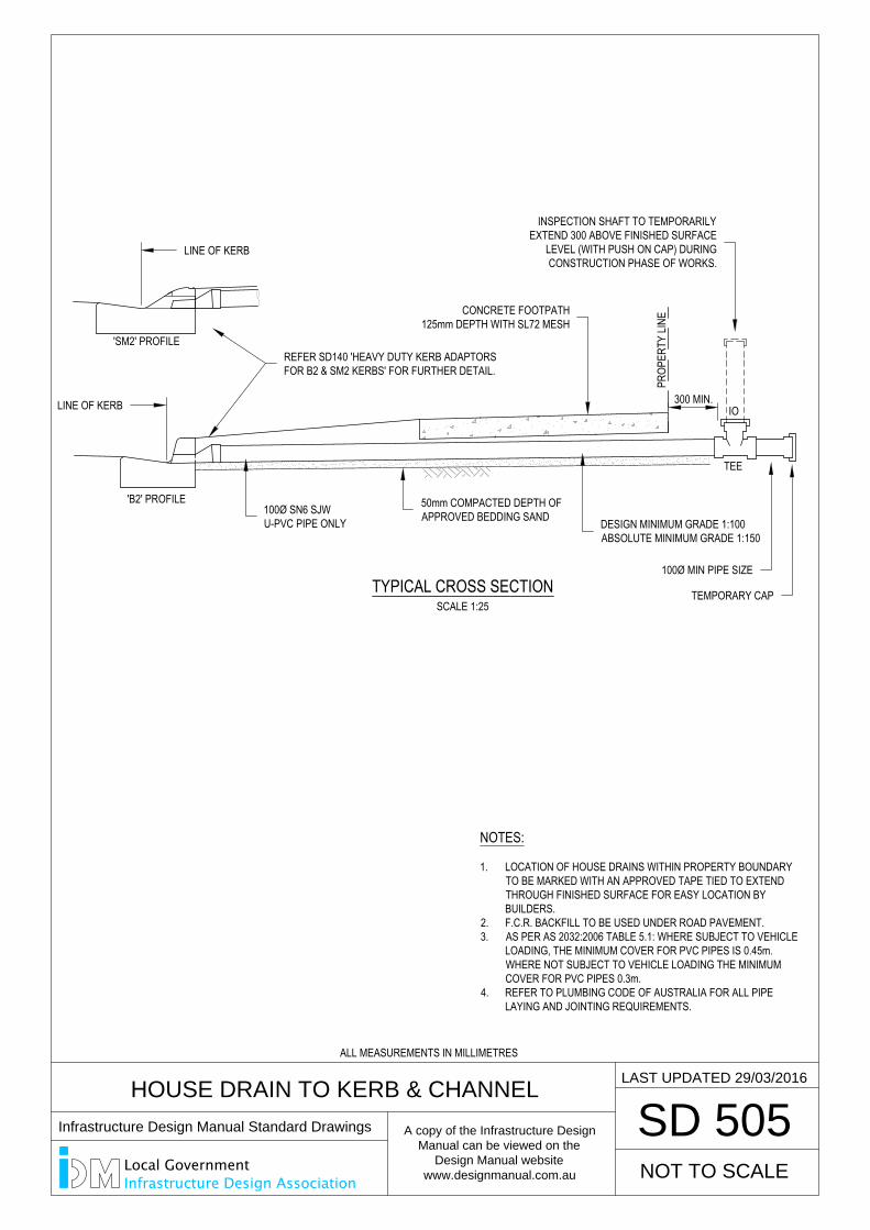
SCALE 1:25TYPICAL CROSS SECTION
300 MIN.
HOUSE DRAIN TO KERB & CHANNEL
SD 505
PROP
ERTY
LINE
'B2' PROFILE
'SM2' PROFILE
IO
TEE
LAST UPDATED 29/03/2016
NOTES:
1. LOCATION OF HOUSE DRAINS WITHIN PROPERTY BOUNDARYTO BE MARKED WITH AN APPROVED TAPE TIED TO EXTENDTHROUGH FINISHED SURFACE FOR EASY LOCATION BYBUILDERS.
2. F.C.R. BACKFILL TO BE USED UNDER ROAD PAVEMENT.3. AS PER AS 2032:2006 TABLE 5.1: WHERE SUBJECT TO VEHICLE
LOADING, THE MINIMUM COVER FOR PVC PIPES IS 0.45m.WHERE NOT SUBJECT TO VEHICLE LOADING THE MINIMUMCOVER FOR PVC PIPES 0.3m.
4. REFER TO PLUMBING CODE OF AUSTRALIA FOR ALL PIPELAYING AND JOINTING REQUIREMENTS.
NOT TO SCALE
50mm COMPACTED DEPTH OFAPPROVED BEDDING SAND DESIGN MINIMUM GRADE 1:100
ABSOLUTE MINIMUM GRADE 1:150
100Ø SN6 SJWU-PVC PIPE ONLY
100Ø MIN PIPE SIZE
TEMPORARY CAP
CONCRETE FOOTPATH125mm DEPTH WITH SL72 MESH
INSPECTION SHAFT TO TEMPORARILYEXTEND 300 ABOVE FINISHED SURFACE
LEVEL (WITH PUSH ON CAP) DURINGCONSTRUCTION PHASE OF WORKS.
REFER SD140 'HEAVY DUTY KERB ADAPTORSFOR B2 & SM2 KERBS' FOR FURTHER DETAIL.
LINE OF KERB
LINE OF KERB
ALL MEASUREMENTS IN MILLIMETRES
Infrastructure Design Manual Standard Drawings
A copy of the Infrastructure Design
Manual can be viewed on the
Design Manual website
www.designmanual.com.au
Local GovernmentInfrastructure Design Association
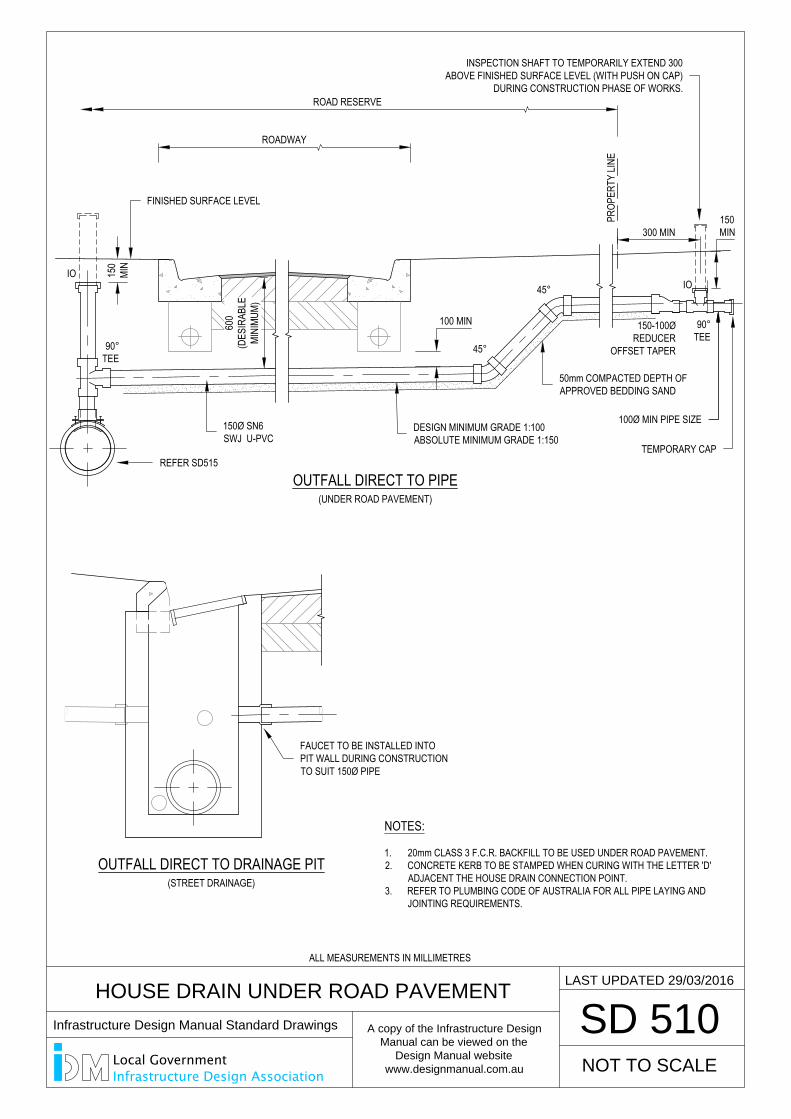
SD 510
LAST UPDATED 29/03/2016
300 MIN
PROP
ERTY
LINE
600
(DES
IRAB
LEMI
NIMU
M)
100 MIN
45°
45°IO
90°TEE
ROADWAY
ROAD RESERVE
NOTES:
1. 20mm CLASS 3 F.C.R. BACKFILL TO BE USED UNDER ROAD PAVEMENT.2. CONCRETE KERB TO BE STAMPED WHEN CURING WITH THE LETTER 'D'
ADJACENT THE HOUSE DRAIN CONNECTION POINT.3. REFER TO PLUMBING CODE OF AUSTRALIA FOR ALL PIPE LAYING AND
JOINTING REQUIREMENTS.
150
MIN
OUTFALL DIRECT TO DRAINAGE PIT
OUTFALL DIRECT TO PIPE
(STREET DRAINAGE)
(UNDER ROAD PAVEMENT)
HOUSE DRAIN UNDER ROAD PAVEMENT
NOT TO SCALE
IO
90°TEE
150-100ØREDUCER
OFFSET TAPER
150MIN
DESIGN MINIMUM GRADE 1:100ABSOLUTE MINIMUM GRADE 1:150
50mm COMPACTED DEPTH OFAPPROVED BEDDING SAND
150Ø SN6SWJ U-PVC
100Ø MIN PIPE SIZE
TEMPORARY CAP
INSPECTION SHAFT TO TEMPORARILY EXTEND 300ABOVE FINISHED SURFACE LEVEL (WITH PUSH ON CAP)
DURING CONSTRUCTION PHASE OF WORKS.
REFER SD515
FINISHED SURFACE LEVEL
FAUCET TO BE INSTALLED INTOPIT WALL DURING CONSTRUCTIONTO SUIT 150Ø PIPE
ALL MEASUREMENTS IN MILLIMETRES
Infrastructure Design Manual Standard Drawings
A copy of the Infrastructure Design
Manual can be viewed on the
Design Manual website
www.designmanual.com.au
Local GovernmentInfrastructure Design Association
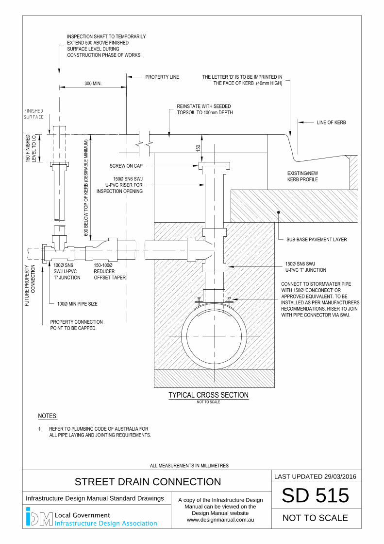
STREET DRAIN CONNECTION
SD 515
NOT TO SCALETYPICAL CROSS SECTION
FUTU
RE P
ROPE
RTY
CONN
ECTI
ON
EXISTING/NEWKERB PROFILE
150
300 MIN.
100Ø SN6SWJ U-PVC'T' JUNCTION
LAST UPDATED 29/03/2016
NOT TO SCALE
150-100ØREDUCEROFFSET TAPER
600 B
ELOW
TOP
OF
KERB
(DES
IRAB
LE M
INIM
UM)
150 F
INIS
HED
LEVE
L TO
I.O.
NOTES:
1. REFER TO PLUMBING CODE OF AUSTRALIA FORALL PIPE LAYING AND JOINTING REQUIREMENTS.
REINSTATE WITH SEEDEDTOPSOIL TO 100mm DEPTH
THE LETTER 'D' IS TO BE IMPRINTED INTHE FACE OF KERB (40mm HIGH)
CONNECT TO STORMWATER PIPEWITH 150Ø 'CONCONECT' ORAPPROVED EQUIVALENT. TO BEINSTALLED AS PER MANUFACTURERSRECOMMENDATIONS. RISER TO JOINWITH PIPE CONNECTOR VIA SWJ.
150Ø SN6 SWJU-PVC 'T' JUNCTION
SUB-BASE PAVEMENT LAYER
PROPERTY CONNECTIONPOINT TO BE CAPPED.
100Ø MIN PIPE SIZE
LINE OF KERB
PROPERTY LINE
INSPECTION SHAFT TO TEMPORARILYEXTEND 500 ABOVE FINISHEDSURFACE LEVEL DURINGCONSTRUCTION PHASE OF WORKS.
150Ø SN6 SWJU-PVC RISER FOR
INSPECTION OPENING
SCREW ON CAP
ALL MEASUREMENTS IN MILLIMETRES
Infrastructure Design Manual Standard Drawings
A copy of the Infrastructure Design
Manual can be viewed on the
Design Manual website
www.designmanual.com.au
Local GovernmentInfrastructure Design Association
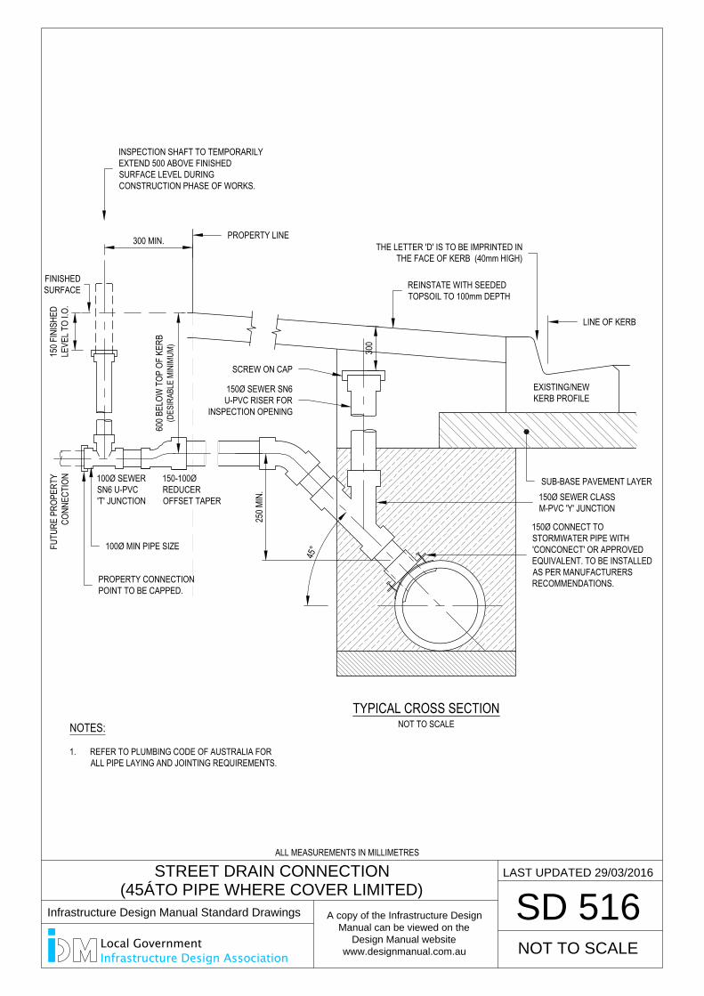
STREET DRAIN CONNECTION
(45° TO PIPE WHERE COVER LIMITED)
SD 516
LAST UPDATED 29/03/2016
FUTU
RE P
ROPE
RTY
CONN
ECTI
ON
600 B
ELOW
TOP
OF
KERB
(DES
IRAB
LE M
INIM
UM)
300 MIN.
100Ø SEWERSN6 U-PVC'T' JUNCTION
150 F
INIS
HED
LEVE
L TO
I.O.
FINISHEDSURFACE
NOT TO SCALETYPICAL CROSS SECTION
EXISTING/NEWKERB PROFILE
300
250 M
IN.
NOT TO SCALE
150-100ØREDUCEROFFSET TAPER
45°
NOTES:
1. REFER TO PLUMBING CODE OF AUSTRALIA FORALL PIPE LAYING AND JOINTING REQUIREMENTS.
REINSTATE WITH SEEDEDTOPSOIL TO 100mm DEPTH
THE LETTER 'D' IS TO BE IMPRINTED INTHE FACE OF KERB (40mm HIGH)
150Ø CONNECT TOSTORMWATER PIPE WITH'CONCONECT' OR APPROVEDEQUIVALENT. TO BE INSTALLEDAS PER MANUFACTURERSRECOMMENDATIONS.
150Ø SEWER CLASSM-PVC 'Y' JUNCTION
SUB-BASE PAVEMENT LAYER
PROPERTY CONNECTIONPOINT TO BE CAPPED.
100Ø MIN PIPE SIZE
PROPERTY LINE
INSPECTION SHAFT TO TEMPORARILYEXTEND 500 ABOVE FINISHEDSURFACE LEVEL DURINGCONSTRUCTION PHASE OF WORKS.
150Ø SEWER SN6U-PVC RISER FOR
INSPECTION OPENING
SCREW ON CAP
LINE OF KERB
ALL MEASUREMENTS IN MILLIMETRES
Infrastructure Design Manual Standard Drawings
A copy of the Infrastructure Design
Manual can be viewed on the
Design Manual website
www.designmanual.com.au
Local GovernmentInfrastructure Design Association
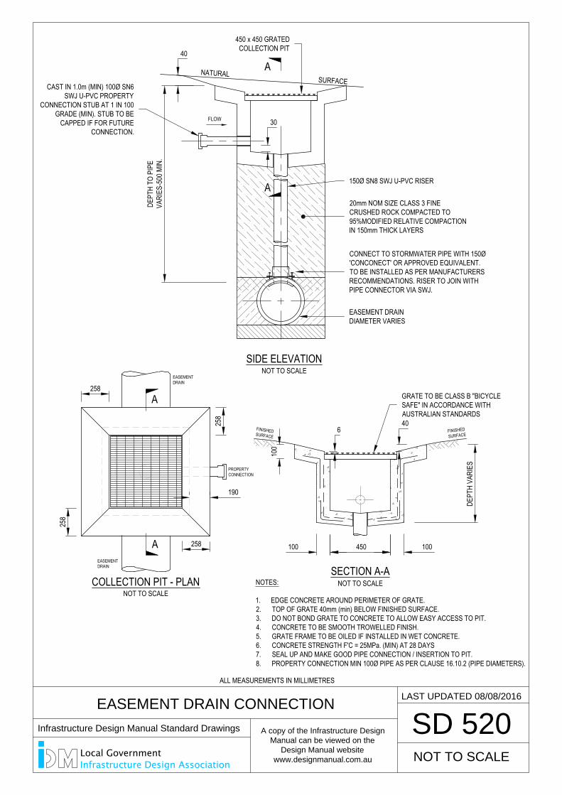
258
258
258
EASEMENT DRAIN CONNECTION
SD 520
NOT TO SCALESECTION A-A
NOT TO SCALECOLLECTION PIT - PLAN
SIDE ELEVATIONNOT TO SCALE
NATURALSURFACE
DEPT
H TO
PIP
EVA
RIES
-500
MIN
.
40
NOTES:
1. EDGE CONCRETE AROUND PERIMETER OF GRATE.2. TOP OF GRATE 40mm (min) BELOW FINISHED SURFACE.3. DO NOT BOND GRATE TO CONCRETE TO ALLOW EASY ACCESS TO PIT.4. CONCRETE TO BE SMOOTH TROWELLED FINISH.5. GRATE FRAME TO BE OILED IF INSTALLED IN WET CONCRETE.6. CONCRETE STRENGTH F'C = 25MPa. (MIN) AT 28 DAYS7. SEAL UP AND MAKE GOOD PIPE CONNECTION / INSERTION TO PIT.8. PROPERTY CONNECTION MIN 100Ø PIPE AS PER CLAUSE 16.10.2 (PIPE DIAMETERS).
LAST UPDATED 08/08/2016
100
450100
FINISHEDSURFACE
40
A
A
DEPT
H VA
RIES
258
6 FINISHEDSURFACE
100
190
NOT TO SCALE
FLOW
A
A
30
PROPERTYCONNECTION
EASEMENTDRAIN
EASEMENTDRAIN
GRATE TO BE CLASS B "BICYCLESAFE" IN ACCORDANCE WITHAUSTRALIAN STANDARDS
CAST IN 1.0m (MIN) 100Ø SN6SWJ U-PVC PROPERTY
CONNECTION STUB AT 1 IN 100GRADE (MIN). STUB TO BE
CAPPED IF FOR FUTURECONNECTION.
EASEMENT DRAINDIAMETER VARIES
CONNECT TO STORMWATER PIPE WITH 150Ø'CONCONECT' OR APPROVED EQUIVALENT.TO BE INSTALLED AS PER MANUFACTURERSRECOMMENDATIONS. RISER TO JOIN WITHPIPE CONNECTOR VIA SWJ.
20mm NOM SIZE CLASS 3 FINECRUSHED ROCK COMPACTED TO95%MODIFIED RELATIVE COMPACTIONIN 150mm THICK LAYERS
150Ø SN8 SWJ U-PVC RISER
450 x 450 GRATEDCOLLECTION PIT
ALL MEASUREMENTS IN MILLIMETRES
Infrastructure Design Manual Standard Drawings
A copy of the Infrastructure Design
Manual can be viewed on the
Design Manual website
www.designmanual.com.au
Local GovernmentInfrastructure Design Association
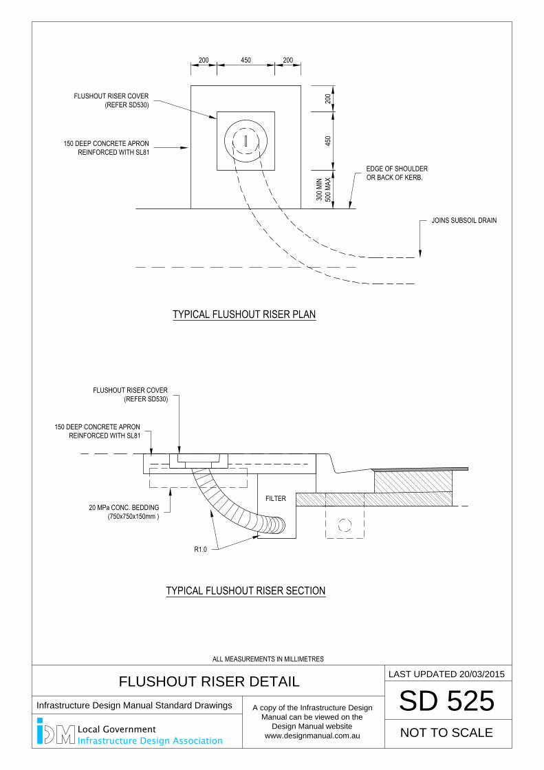
FLUSHOUT RISER DETAIL
SD 525
NOT TO SCALE
LAST UPDATED 20/03/2015
TYPICAL FLUSHOUT RISER PLAN30
0 MIN
500 M
AX45
020
0
200 200450
FILTER
TYPICAL FLUSHOUT RISER SECTION
FLUSHOUT RISER COVER(REFER SD530)
EDGE OF SHOULDEROR BACK OF KERB.
JOINS SUBSOIL DRAIN
150 DEEP CONCRETE APRONREINFORCED WITH SL81
FLUSHOUT RISER COVER(REFER SD530)
150 DEEP CONCRETE APRONREINFORCED WITH SL81
20 MPa CONC. BEDDING(750x750x150mm )
R1.0
ALL MEASUREMENTS IN MILLIMETRES
Infrastructure Design Manual Standard Drawings
A copy of the Infrastructure Design
Manual can be viewed on the
Design Manual website
www.designmanual.com.au
Local GovernmentInfrastructure Design Association
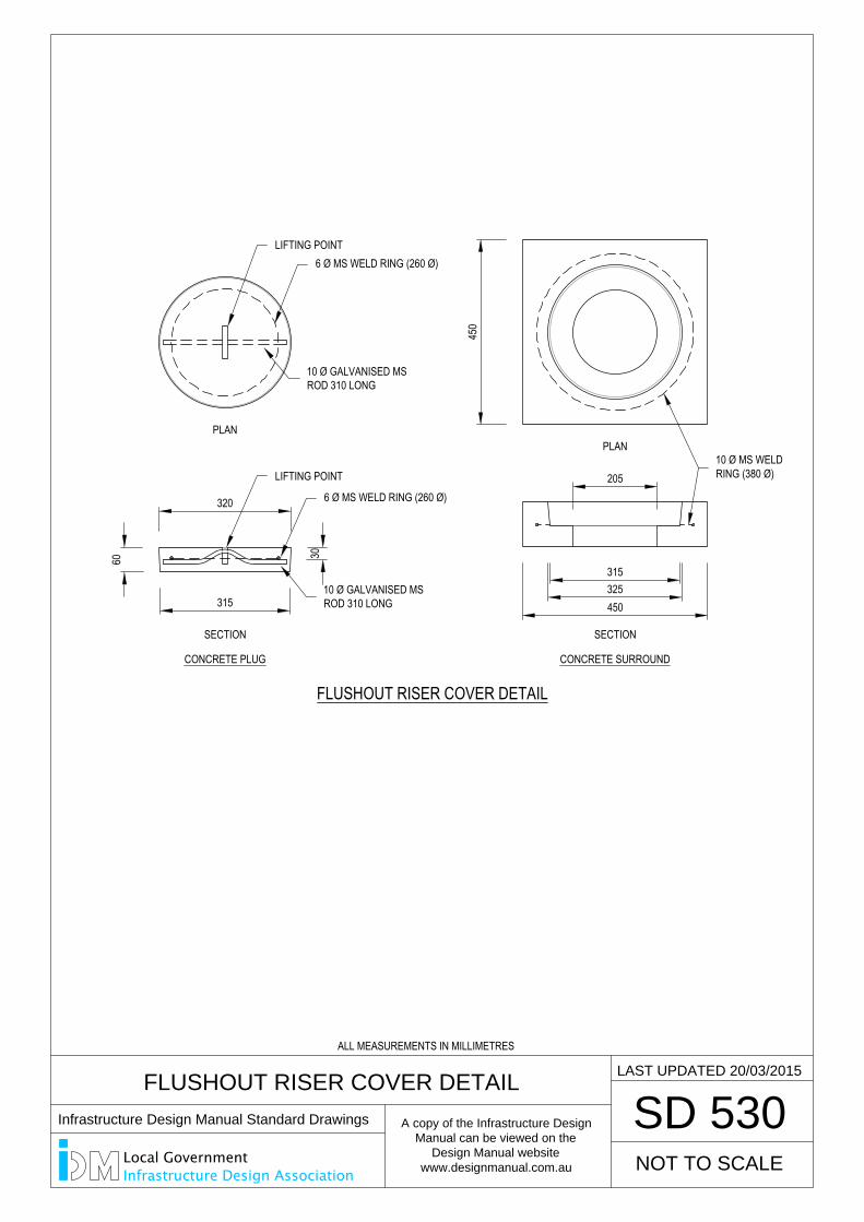
CONCRETE PLUG
320
315
60 30
SECTION
PLAN
FLUSHOUT RISER COVER DETAIL
450
450325315
205
CONCRETE SURROUND
SECTION
PLAN
FLUSHOUT RISER COVER DETAIL
SD 530
NOT TO SCALE
LAST UPDATED 20/03/2015
10 Ø MS WELDRING (380 Ø)
10 Ø GALVANISED MSROD 310 LONG
6 Ø MS WELD RING (260 Ø)
LIFTING POINT
LIFTING POINT6 Ø MS WELD RING (260 Ø)
10 Ø GALVANISED MSROD 310 LONG
ALL MEASUREMENTS IN MILLIMETRES
Infrastructure Design Manual Standard Drawings
A copy of the Infrastructure Design
Manual can be viewed on the
Design Manual website
www.designmanual.com.au
Local GovernmentInfrastructure Design Association
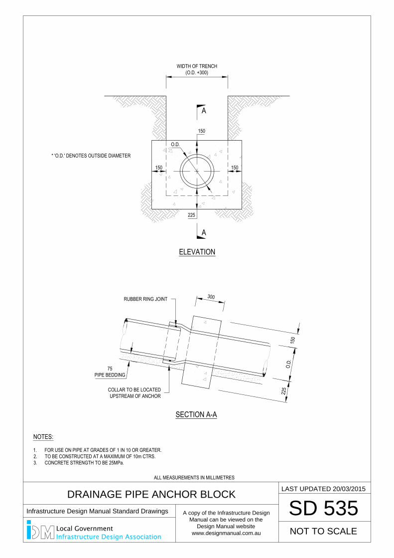
DRAINAGE PIPE ANCHOR BLOCK
SD 535
LAST UPDATED 20/03/2015
WIDTH OF TRENCH(O.D. +300)
150
225
150150
O.D.
* 'O.D.' DENOTES OUTSIDE DIAMETER
ELEVATION
A
A
150
225
O.D.
75PIPE BEDDING
NOTES:
1. FOR USE ON PIPE AT GRADES OF 1 IN 10 OR GREATER.2. TO BE CONSTRUCTED AT A MAXIMUM OF 10m CTRS.3. CONCRETE STRENGTH TO BE 25MPa.
SECTION A-A
300
NOT TO SCALE
COLLAR TO BE LOCATEDUPSTREAM OF ANCHOR
RUBBER RING JOINT
ALL MEASUREMENTS IN MILLIMETRES
Infrastructure Design Manual Standard Drawings
A copy of the Infrastructure Design
Manual can be viewed on the
Design Manual website
www.designmanual.com.au
Local GovernmentInfrastructure Design Association
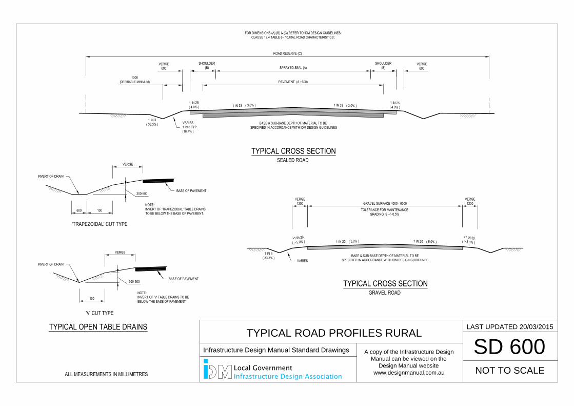
SD 600
LAST UPDATED 20/03/2015
TYPICAL ROAD PROFILES RURAL
NOT TO SCALE
ROAD RESERVE (C)
PAVEMENT (A +600)
SHOULDER(B)
VERGE600
SHOULDER(B)SPRAYED SEAL (A)
1000(DESIRABLE MINIMUM)
VERGE600
1 IN 33 ( 3.0% ) 1 IN 33 ( 3.0% )1 IN 25( 4.0% )
1 IN 25( 4.0% )
1 IN 3( 33.3% )
1 IN 3( 33.3% )
1 IN 20 ( 5.0% )>1 IN 20( > 5.0% ) 1 IN 20 ( 5.0% )
BASE & SUB-BASE DEPTH OF MATERIAL TO BE SPECIFIED IN ACCORDANCE WITH IDM DESIGN GUIDELINES
BASE & SUB-BASE DEPTH OF MATERIAL TO BESPECIFIED IN ACCORDANCE WITH IDM DESIGN GUIDELINES
FOR DIMENSIONS (A) (B) & (C) REFER TO IDM DESIGN GUIDELINES:CLAUSE 12.4 TABLE 6 - 'RURAL ROAD CHARACTERISTICS'.
VERGE1200
VERGE1200GRAVEL SURFACE 4000 - 6000
TOLERANCE FOR MAINTENANCEGRADING IS +/- 0.5%
TYPICAL CROSS SECTIONSEALED ROAD
TYPICAL CROSS SECTIONGRAVEL ROAD
TYPICAL OPEN TABLE DRAINS
'V' CUT TYPE
VERGE
100600
VERGE
100
'TRAPEZOIDAL' CUT TYPE
NOTE:INVERT OF 'TRAPEZOIDAL' TABLE DRAINSTO BE BELOW THE BASE OF PAVEMENT.
NOTE:INVERT OF 'V' TABLE DRAINS TO BEBELOW THE BASE OF PAVEMENT.
>1 IN 20( > 5.0% )
BASE OF PAVEMENT
INVERT OF DRAIN
BASE OF PAVEMENT
VARIES1 IN 6 TYP.(16.7% )
INVERT OF DRAIN
VARIES
300-500
300-500
SD 600
LAST UPDATED 20/03/2015
TYPICAL ROAD PROFILES RURAL
NOT TO SCALE
Infrastructure Design Manual Standard Drawings
A copy of the Infrastructure Design
Manual can be viewed on the
Design Manual website
www.designmanual.com.au
Local GovernmentInfrastructure Design AssociationALL MEASUREMENTS IN MILLIMETRES
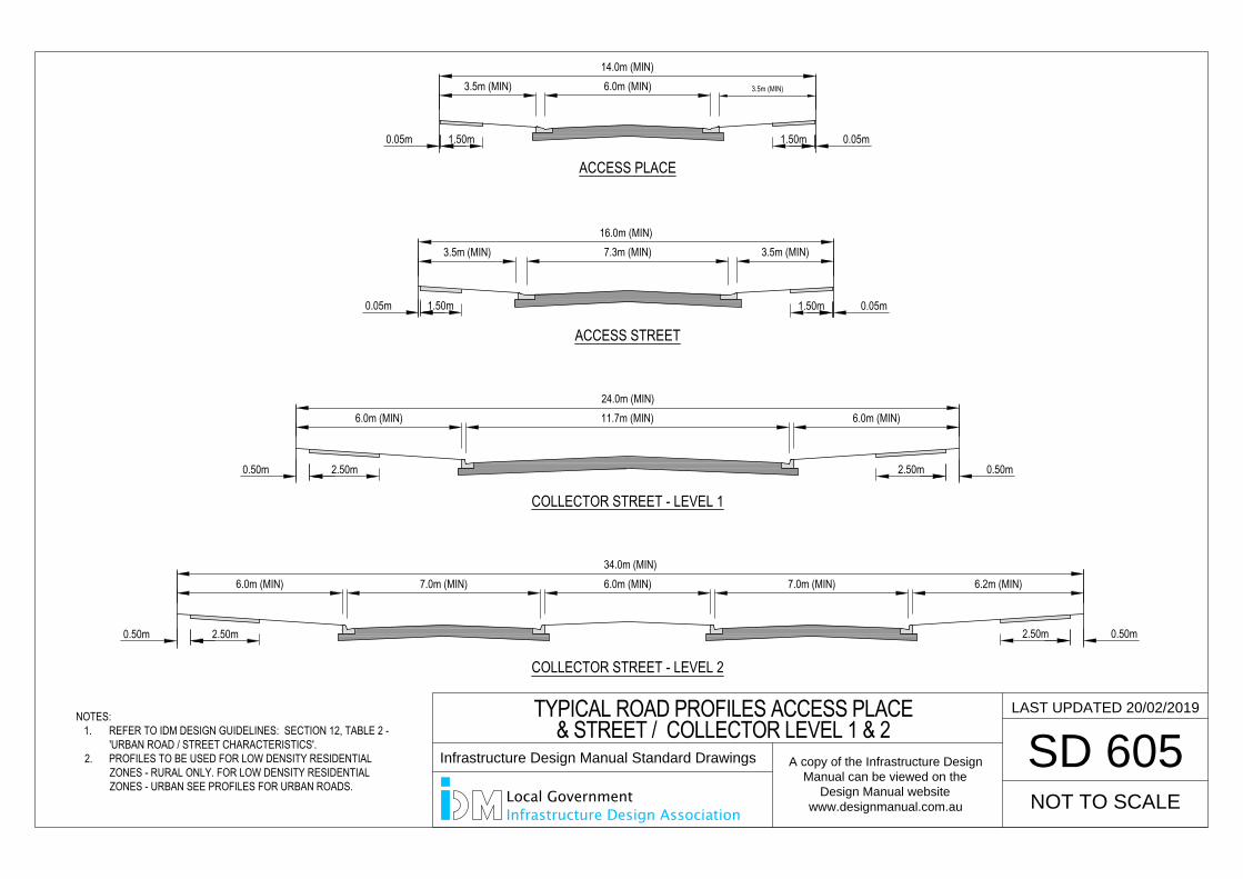
SD 605
LAST UPDATED 20/02/2019
6.0m (MIN) 3.5m (MIN)3.5m (MIN)14.0m (MIN)
0.05m 1.50m 0.05m1.50m
ACCESS PLACE
7.3m (MIN)3.5m (MIN)16.0m (MIN)
1.50m
ACCESS STREET
0.05m1.50m
3.5m (MIN)
0.50m 2.50m
11.7m (MIN)24.0m (MIN)
COLLECTOR STREET - LEVEL 1
6.0m (MIN)6.0m (MIN)
0.50m2.50m
7.0m (MIN)34.0m (MIN)
COLLECTOR STREET - LEVEL 2
0.50m 2.50m
6.0m (MIN) 7.0m (MIN) 6.2m (MIN)6.0m (MIN)
0.50m2.50m
NOT TO SCALE
TYPICAL ROAD PROFILES ACCESS PLACE& STREET / COLLECTOR LEVEL 1 & 2
NOTES:1. REFER TO IDM DESIGN GUIDELINES: SECTION 12, TABLE 2 -
'URBAN ROAD / STREET CHARACTERISTICS'.2. PROFILES TO BE USED FOR LOW DENSITY RESIDENTIAL
ZONES - RURAL ONLY. FOR LOW DENSITY RESIDENTIALZONES - URBAN SEE PROFILES FOR URBAN ROADS.
0.05m
SD 605
LAST UPDATED 20/02/2019
NOT TO SCALE
TYPICAL ROAD PROFILES ACCESS PLACE& STREET / COLLECTOR LEVEL 1 & 2
Infrastructure Design Manual Standard Drawings
A copy of the Infrastructure Design
Manual can be viewed on the
Design Manual website
www.designmanual.com.au
Local GovernmentInfrastructure Design Association
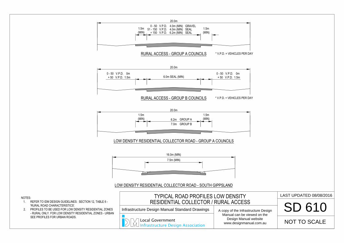
SD 610
LAST UPDATED 08/08/2016
LOW DENSITY RESIDENTIAL COLLECTOR ROAD - GROUP A COUNCILS
LOW DENSITY RESIDENTIAL COLLECTOR ROAD - SOUTH GIPPSLAND
7.5m (MIN)16.0m (MIN)
6.2m1.5m(MIN)
20.0m1.5m(MIN)
RURAL ACCESS - GROUP A COUNCILS
RURAL ACCESS - GROUP B COUNCILS
1.5m(MIN)
1.5m(MIN)
4.0m (MIN)0 - 50 V.P.D.4.0m (MIN)51 - 150 V.P.D.6.2m (MIN)+ 150 V.P.D.
GRAVELSEALSEAL
* V.P.D. = VEHICLES PER DAY
20.0m
0 - 50 V.P.D. 0m + 50 V.P.D. 1.5m6.0m SEAL (MIN)
* V.P.D. = VEHICLES PER DAY
20.0m
0 - 50 V.P.D. 0m + 50 V.P.D. 1.5m
NOT TO SCALE
GROUP A7.0m GROUP B
NOTES:1. REFER TO IDM DESIGN GUIDELINES: SECTION 12, TABLE 6 -
'RURAL ROAD CHARACTERISTICS'.2. PROFILES TO BE USED FOR LOW DENSITY RESIDENTIAL ZONES
- RURAL ONLY. FOR LOW DENSITY RESIDENTIAL ZONES - URBANSEE PROFILES FOR URBAN ROADS.
TYPICAL ROAD PROFILES LOW DENSITYRESIDENTIAL COLLECTOR / RURAL ACCESS
SD 610
LAST UPDATED 08/08/2016
NOT TO SCALE
TYPICAL ROAD PROFILES LOW DENSITYRESIDENTIAL COLLECTOR / RURAL ACCESS
Infrastructure Design Manual Standard Drawings
A copy of the Infrastructure Design
Manual can be viewed on the
Design Manual website
www.designmanual.com.au
Local GovernmentInfrastructure Design Association
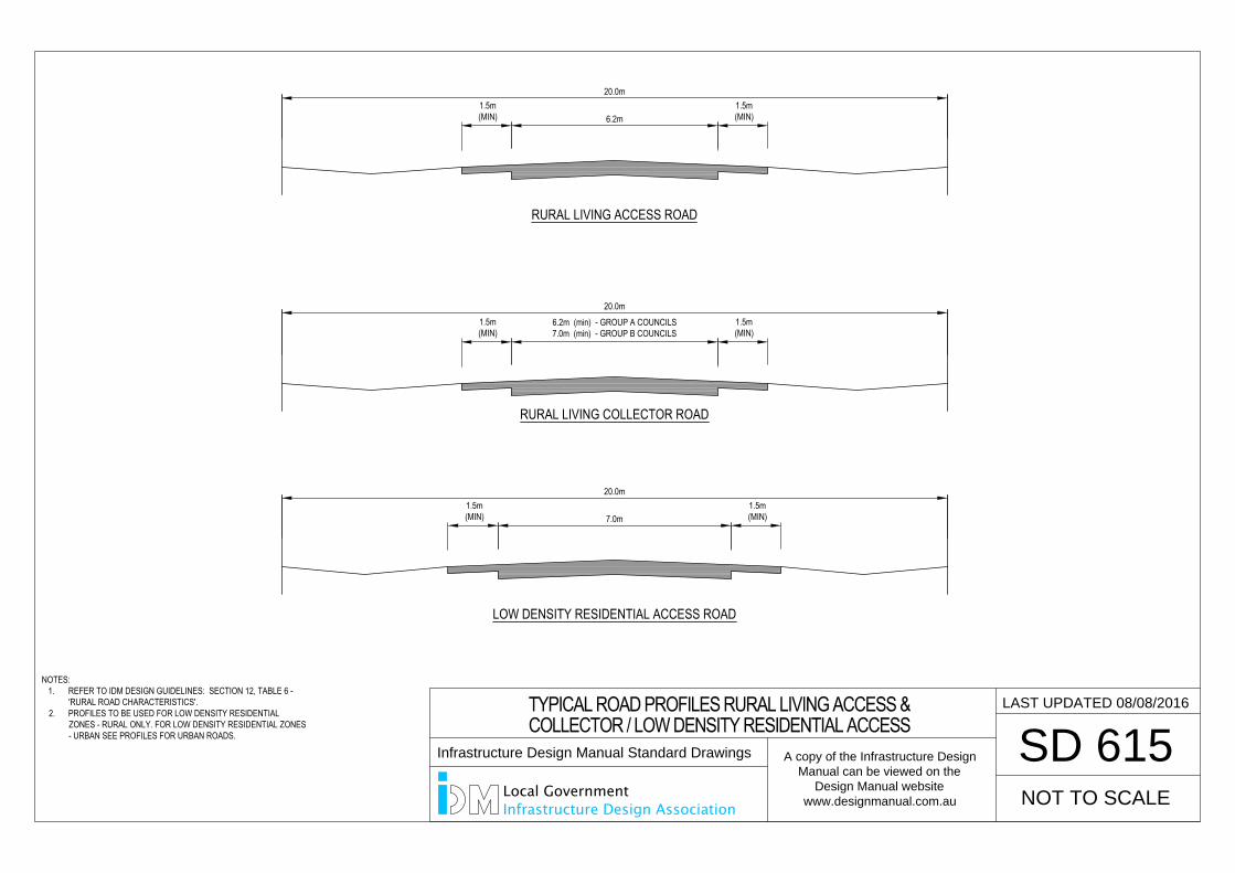
6.2m
20.0m
RURAL LIVING ACCESS ROAD
6.2m (min) - GROUP A COUNCILS7.0m (min) - GROUP B COUNCILS
20.0m1.5m(MIN)
RURAL LIVING COLLECTOR ROAD
LOW DENSITY RESIDENTIAL ACCESS ROAD
7.0m
20.0m
NOTES:1. REFER TO IDM DESIGN GUIDELINES: SECTION 12, TABLE 6 -
'RURAL ROAD CHARACTERISTICS'.2. PROFILES TO BE USED FOR LOW DENSITY RESIDENTIAL
ZONES - RURAL ONLY. FOR LOW DENSITY RESIDENTIAL ZONES- URBAN SEE PROFILES FOR URBAN ROADS.
1.5m(MIN)
1.5m(MIN)
1.5m(MIN)
1.5m(MIN)
1.5m(MIN)
SD 615
LAST UPDATED 08/08/2016
NOT TO SCALE
TYPICAL ROAD PROFILES RURAL LIVING ACCESS &COLLECTOR / LOW DENSITY RESIDENTIAL ACCESS
Infrastructure Design Manual Standard Drawings
A copy of the Infrastructure Design
Manual can be viewed on the
Design Manual website
www.designmanual.com.au
Local GovernmentInfrastructure Design Association
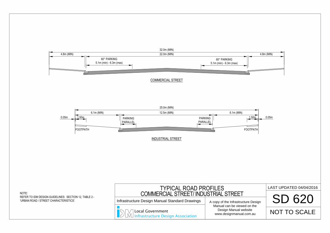
COMMERCIAL STREET
32.0m (MIN)4.8m (MIN)4.8m (MIN) 22.0m (MIN)
60° PARKING5.1m (min) - 6.3m (max)
60° PARKING5.1m (min) - 6.3m (max)
12.5m (MIN)25.0m (MIN)
INDUSTRIAL STREET
6.1m (MIN)6.1m (MIN)
PARKINGPARALLEL
PARKINGPARALLEL
NOTE:REFER TO IDM DESIGN GUIDELINES: SECTION 12, TABLE 2 -'URBAN ROAD / STREET CHARACTERISTICS'.
0.05m 1.50m 0.05m1.50m
FOOTPATH FOOTPATH
LAST UPDATED 04/04/2016
SD 620
NOT TO SCALE
TYPICAL ROAD PROFILESCOMMERCIAL STREET/ INDUSTRIAL STREET
Infrastructure Design Manual Standard Drawings
A copy of the Infrastructure Design
Manual can be viewed on the
Design Manual website
www.designmanual.com.au
Local GovernmentInfrastructure Design Association
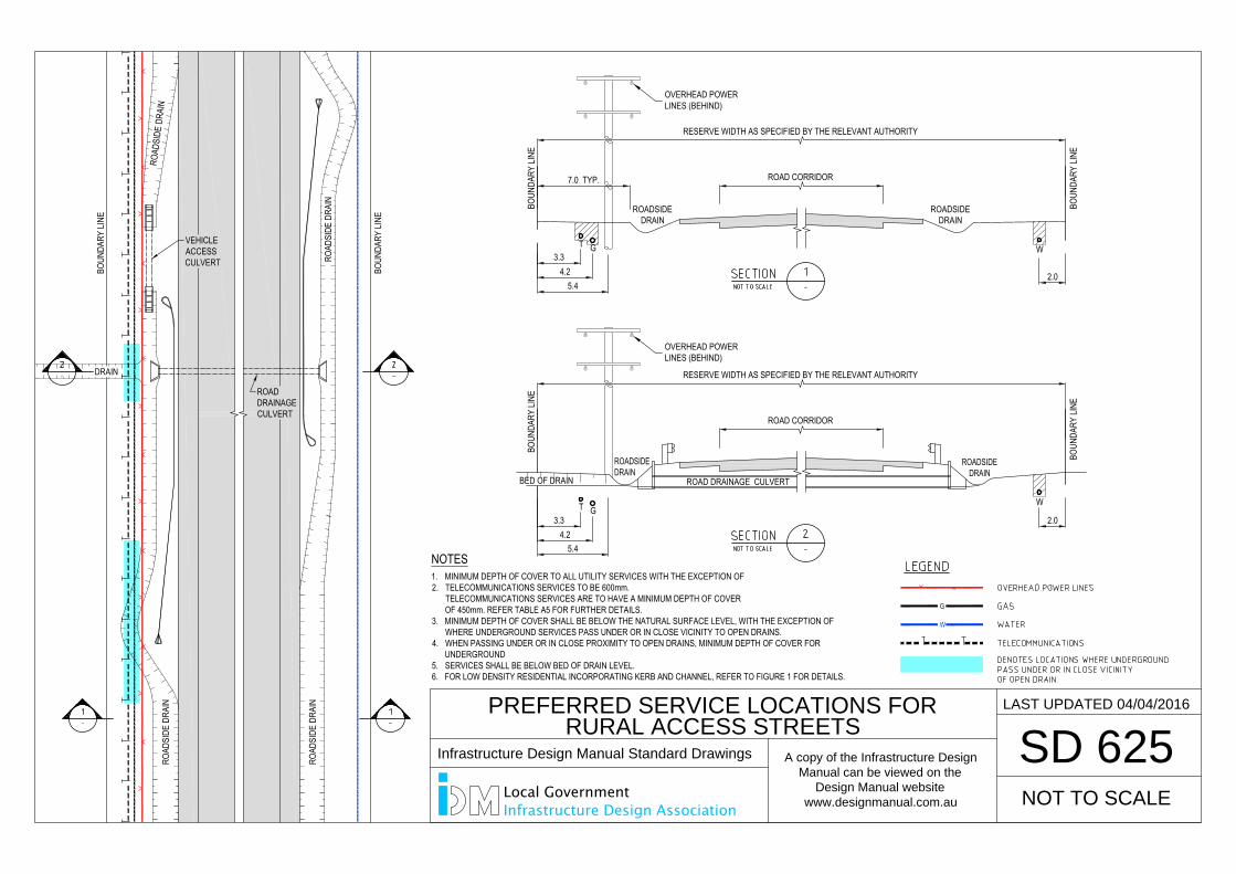
PREFERRED SERVICE LOCATIONS FOR
RURAL ACCESS STREETS
SD 625
NOT TO SCALE
LAST UPDATED 04/04/2016
ROADSIDEDRAIN
ROAD DRAINAGE CULVERT
BOUN
DARY
LINE
ROADSIDEDRAIN
BOUN
DARY
LINE
BOUN
DARY
LINE
7.0 TYP.
G3.3
4.25.4
ROADSIDEDRAIN
BOUN
DARY
LINE
ROADSIDEDRAIN
G3.3
4.25.4
ROADDRAINAGECULVERT
BOUN
DARY
LINE
WW
WW
WW
WW
WW
WW
WW
WW
WW
WW
WW
WW
WW
WW
WW
WW
WW
WW
WW
WW
WW
WW
WW
WW
WW
WW
WW
WW
WW
WW
WW
WW
WW
WW
WW
WW
WW
WW
WW
WW
WW
WW
WW
WW
WW
WW
WW
WW
WW
WW
WW
WW
WW
WW
WW
WW
WW
WW
WW
WW
WW
WW
WW
WW
WW
WW
WW
WW
WW
WW
WW
WW
WW
WW
WW
WW
WW
WW
WW
WW
WW
WW
WW
WW
WW
WW
WW
WW
WW
WW
WW
WW
WW
WW
WW
WW
W
ROAD
SIDE
DRA
IN
ROAD
SIDE
DRA
IN
DRAIN
ROAD
SIDE
DRA
IN
BOUN
DARY
LINE
ROAD
SIDE
DRA
IN
GG
GG
GG
GG
GG
GG
GG
GG
GG
GG
GG
GG
GG
GG
GG
GG
GG
GG
GG
GG
GG
GG
GG
GG
GG
GG
GG
GG
GG
GG
GG
GG
GG
GG
GG
GG
GG
GG
GG
GG
GG
GG
GG
GG
GG
GG
GG
GG
GG
GG
GG
GG
GG
GG
GG
GG
GG
GG
GG
GG
GG
GG
GG
GG
GG
GG
GG
GG
GG
GG
GG
GG
GG
GG
GG
GG
GG
GG
GG
GG
GG
GG
GG
GG
GG
GG
GG
GG
GG
GG
GG
GG
GG
GG
GG
GG
G
BED OF DRAIN
W
2.0
W
2.0
T
TVEHICLEACCESSCULVERT
ROAD CORRIDOR
RESERVE WIDTH AS SPECIFIED BY THE RELEVANT AUTHORITY
ROAD CORRIDOR
RESERVE WIDTH AS SPECIFIED BY THE RELEVANT AUTHORITY
G
W
NOTES1. MINIMUM DEPTH OF COVER TO ALL UTILITY SERVICES WITH THE EXCEPTION OF2. TELECOMMUNICATIONS SERVICES TO BE 600mm.
TELECOMMUNICATIONS SERVICES ARE TO HAVE A MINIMUM DEPTH OF COVEROF 450mm. REFER TABLE A5 FOR FURTHER DETAILS.
3. MINIMUM DEPTH OF COVER SHALL BE BELOW THE NATURAL SURFACE LEVEL, WITH THE EXCEPTION OFWHERE UNDERGROUND SERVICES PASS UNDER OR IN CLOSE VICINITY TO OPEN DRAINS.
4. WHEN PASSING UNDER OR IN CLOSE PROXIMITY TO OPEN DRAINS, MINIMUM DEPTH OF COVER FORUNDERGROUND
5. SERVICES SHALL BE BELOW BED OF DRAIN LEVEL.6. FOR LOW DENSITY RESIDENTIAL INCORPORATING KERB AND CHANNEL, REFER TO FIGURE 1 FOR DETAILS.
OVERHEAD POWERLINES (BEHIND)
OVERHEAD POWERLINES (BEHIND)
PREFERRED SERVICE LOCATIONS FOR
RURAL ACCESS STREETS
SD 625
NOT TO SCALE
LAST UPDATED 04/04/2016
Infrastructure Design Manual Standard Drawings
A copy of the Infrastructure Design
Manual can be viewed on the
Design Manual website
www.designmanual.com.au
Local GovernmentInfrastructure Design Association
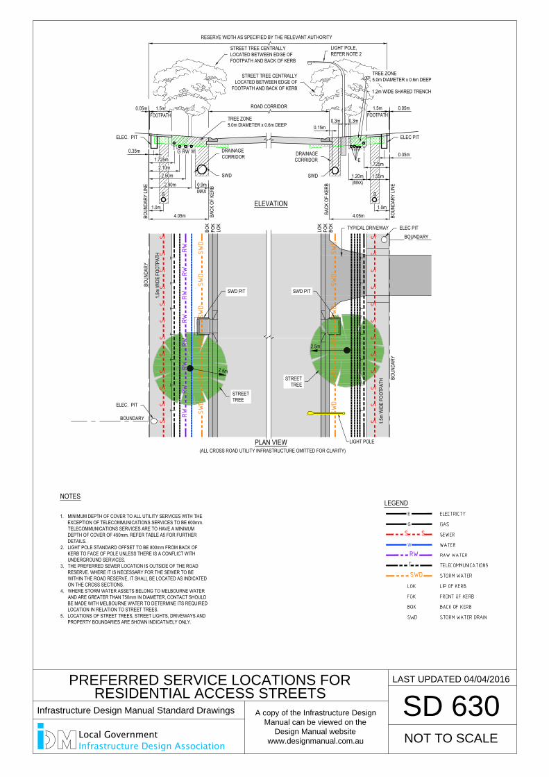
PREFERRED SERVICE LOCATIONS FOR
RESIDENTIAL ACCESS STREETS
SD 630
NOT TO SCALE
LAST UPDATED 04/04/2016
RESERVE WIDTH AS SPECIFIED BY THE RELEVANT AUTHORITY
0.05m
0.35m
1.0m4.05m BO
UNDA
RY LI
NE
BACK
OF
KERB
S
BACK
OF
KERB
4.05m
S
BOUN
DARY
LINE
0.35m
1.0m
G RW
0.05m
ELEVATION
1.5m
WID
E FO
OTPA
TH
1.5m
WID
E FO
OTPA
TH
BOUN
DARY
BOUN
DARY
BOUNDARY
BOK
LOK
LOK
FOK
BOK
FOK
PLAN VIEW(ALL CROSS ROAD UTILITY INFRASTRUCTURE OMITTED FOR CLARITY)
LIGHT POLE
BOUNDARY
T
MAX0.9m
W
1.20m
E
T
SWD
SWD
SWD
SWD
SWD
SWD
SS
SS
SS
SS
SS
SS
GG
GG
GG
GG
GG
GG
GG
GG
GG
GG
GG
GG
GG
GG
GG
GG
GG
GG
GG
GG
GG
GG
GG
GG
GG
GG
GG
GG
GG
GG
GG
GG
GG
GG
GG
GG
GG
GG
GG
GG
WW
WW
WW
WW
WW
WW
WW
WW
WW
WW
WW
WW
WW
WW
WW
WW
WW
WW
WW
WW
WW
WW
WW
WW
WW
WW
WW
WW
WW
WW
WW
WW
WW
WW
WW
WW
WW
WW
WW
WW
RWRW
RWRW
RWRW
RWRW
SS
SS
SS
SS
SS
SS
EE
EE
EE
EE
EE
EE
EE
EE
EE
EE
EE
EE
EE
EE
EE
EE
EE
EE
EE
EE
EE
EE
EE
EE
EE
EE
EE
EE
EE
EE
EE
EE
EE
EE
EE
EE
EE
EE
EE
EE
EE
EE
EE
EE
EE
EE
EE
EE
EE
EE
EE
EE
EE
EE
EE
EE
EE
EE
EE
EE
EE
EE
EE
EE
EE
EE
EE
EE
EE
EE
EE
EE
EE
EE
EE
EE
EE
EE
EE
EE
EE
EE
EE
EE
EE
EE
EE
EE
EE
EE
EE
EE
EE
EE
EE
EE
EE
EE
EE
EE
EE
EE
EE
EE
EE
EE
EE
EE
EE
EE
EE
EE
EE
EE
EE
EE
EE
EE
EE
EE
EE
EE
EE
EE
EE
EE
EE
EE
EE
EE
EE
EE
EE
EE
EE
EE
EE
EE
EE
EE
EE
EE
EE
EE
EE
EE
EE
EE
EE
EE
EE
EE
EE
EE
EE
EE
EE
EE
EE
EE
2.5m
2.5m
FOOTPATH1.5mROAD CORRIDOR
0.15m0.3m 0.3m
(MAX)
SWD
SWD
SWD
SWD
SWD
SWD
1.5mFOOTPATH
LEGEND
G
S S
E
W
RW
SWD
NOTES
1. MINIMUM DEPTH OF COVER TO ALL UTILITY SERVICES WITH THEEXCEPTION OF TELECOMMUNICATIONS SERVICES TO BE 600mm.TELECOMMUNICATIONS SERVICES ARE TO HAVE A MINIMUMDEPTH OF COVER OF 450mm. REFER TABLE A5 FOR FURTHERDETAILS.
2. LIGHT POLE STANDARD OFFSET TO BE 800mm FROM BACK OFKERB TO FACE OF POLE UNLESS THERE IS A CONFLICT WITHUNDERGROUND SERVICES.
3. THE PREFERRED SEWER LOCATION IS OUTSIDE OF THE ROADRESERVE. WHERE IT IS NECESSARY FOR THE SEWER TO BEWITHIN THE ROAD RESERVE, IT SHALL BE LOCATED AS INDICATEDON THE CROSS SECTIONS.
4. WHERE STORM WATER ASSETS BELONG TO MELBOURNE WATERAND ARE GREATER THAN 750mm IN DIAMETER, CONTACT SHOULDBE MADE WITH MELBOURNE WATER TO DETERMINE ITS REQUIREDLOCATION IN RELATION TO STREET TREES.
5. LOCATIONS OF STREET TREES, STREET LIGHTS, DRIVEWAYS ANDPROPERTY BOUNDARIES ARE SHOWN INDICATIVELY ONLY.
TYPICAL DRIVEWAY
LIGHT POLE,REFER NOTE 2
STREET TREE CENTRALLYLOCATED BETWEEN EDGE OFFOOTPATH AND BACK OF KERB
TREE ZONE5.0m DIAMETER x 0.6m DEEP
DRAINAGECORRIDOR
SWD
DRAINAGECORRIDOR
SWD
ELEC. PIT
1.2m WIDE SHARED TRENCH
TREE ZONE5.0m DIAMETER x 0.6m DEEP
STREET TREE CENTRALLYLOCATED BETWEEN EDGE OF
FOOTPATH AND BACK OF KERB
STREETTREE
STREETTREE
SWD PIT SWD PIT
ELEC PIT
ELEC. PIT
ELEC PIT
2.10m
2.90m
2.50m
1.725m
1.55m
1.725m
Infrastructure Design Manual Standard Drawings
A copy of the Infrastructure Design
Manual can be viewed on the
Design Manual website
www.designmanual.com.au
Local GovernmentInfrastructure Design Association
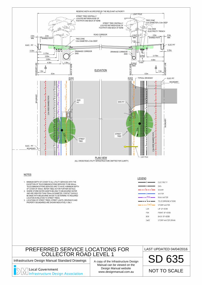
PREFERRED SERVICE LOCATIONS FOR
COLLECTOR ROAD LEVEL 1
SD 635
NOT TO SCALE
LAST UPDATED 04/04/2016
LEGEND
G
S S
E
W
RW
SWD
NOTES
1. MINIMUM DEPTH OF COVER TO ALL UTILITY SERVICES WITH THEEXCEPTION OF TELECOMMUNICATIONS SERVICES TO BE 600mm.TELECOMMUNICATIONS SERVICES ARE TO HAVE A MINIMUM DEPTHOF COVER OF 450mm. REFER TABLE A5 FOR FURTHER DETAILS.
2. WHERE STORM WATER ASSETS BELONG TO MELBOURNE WATERAND ARE GREATER THAN 750mm IN DIAMETER, CONTACT SHOULDBE MADE WITH MELBOURNE WATER TO DETERMINE ITS REQUIREDLOCATION IN RELATION TO STREET TREES.
3. LOCATIONS OF STREET TREES, STREET LIGHTS, DRIVEWAYS ANDPROPERTY BOUNDARIES ARE SHOWN INDICATIVELY ONLY.
0.5m 2.5m
6.0m
0.35m
1.5m
SHARED PATH
S
BOUN
DARY
LINE
BACK
OF
KERB
0.5m
0.35m
1.5m
G
6.0m BOUN
DARY
LINE
3.55m3.95m
4.35m
BACK
OF
KERB
3.175m
S
0.90m
2.5mSHARED PATH
0.3m
E
2.5m
WID
E SH
ARED
PAT
H
BOUNDARY
BOUNDARY
LOK
FOK
BOK
LOK
FOK
BOK
SS
SS
SS
SS
SS
SS
SS
SS
SS
SS
SS
SS
BOUN
DARY
2.5m
WID
E SH
ARED
PAT
H
PLAN VIEW(ALL CROSS ROAD UTILITY INFRASTRUCTURE OMITTED FOR CLARITY)
ELEVATION
1.35mMAX
0.90m
BOUN
DARY
MIN MIN
SWD
SWD
SWD
SWD
SWD
SWD
RWRW
RWRW
RWRW
RWRW
WW
WW
WW
WW
WW
WW
WW
WW
WW
WW
WW
WW
WW
WW
WW
WW
WW
WW
WW
WW
WW
WW
WW
WW
WW
WW
WW
WW
WW
WW
WW
WW
WW
WW
WW
WW
WW
WW
WW
WW
GG
GG
GG
GG
GG
GG
GG
GG
GG
GG
GG
GG
GG
GG
GG
GG
GG
GG
GG
GG
GG
GG
GG
GG
GG
GG
GG
GG
GG
GG
GG
GG
GG
GG
GG
GG
GG
GG
GG
GG
T
3.175m
SWD
SWD
SWD
SWD
SWD
SWD
EE
EE
EE
EE
EE
EE
EE
EE
EE
EE
EE
EE
EE
EE
EE
EE
EE
EE
EE
EE
EE
EE
EE
EE
EE
EE
EE
EE
EE
EE
EE
EE
EE
EE
EE
EE
EE
EE
EE
EE
EE
EE
EE
EE
EE
EE
EE
EE
EE
EE
EE
EE
EE
EE
EE
EE
EE
EE
EE
EE
EE
EE
EE
EE
EE
EE
EE
EE
EE
EE
EE
EE
EE
EE
EE
EE
EE
EE
EE
EE
EE
EE
EE
EE
EE
EE
EE
EE
EE
EE
EE
EE
EE
EE
EE
EE
EE
EE
EE
EE
EE
EE
EE
EE
EE
EE
EE
EE
EE
EE
EE
EE
EE
EE
EE
EE
EE
EE
EE
EE
EE
EE
EE
EE
EE
EE
EE
EE
EE
EE
EE
EE
EE
EE
EE
EE
EE
EE
EE
EE
EE
EE
EE
EE
EE
EE
EE
EE
EE
EE
EE
EE
EE
EE
EE
EE
EE
EE
EE
EE
W T
0.8mMIN
4.00m0.45m
CL
2.5m2.5
m
RW
RESERVE WIDTH AS SPECIFIED BY THE RELEVANT AUTHORITY
ROAD CORRIDOR
STREET TREE CENTRALLYLOCATED BETWEEN EDGE OFFOOTPATH AND BACK OF KERB
TREE ZONE5.0m DIAMETER x 0.6m DEEP
DRAINAGE CORRIDORSWD
DRAINAGE CORRIDORSWD
ELEC PIT
0.9m WIDEELECTRICITY TRENCH
TREE ZONE5.0m DIAMETER x 0.6m DEEPSTREET TREE CENTRALLY
LOCATED BETWEEN EDGE OFFOOTPATH AND BACK OF KERB
LIGHT POLE
ELEC. PIT
STREETTREE
SWDPIT
STREETTREE
SWD PIT
TYPICAL DRIVEWAY ELEC PIT
LIGHT POLE
ELEC. PIT
Infrastructure Design Manual Standard Drawings
A copy of the Infrastructure Design
Manual can be viewed on the
Design Manual website
www.designmanual.com.au
Local GovernmentInfrastructure Design Association
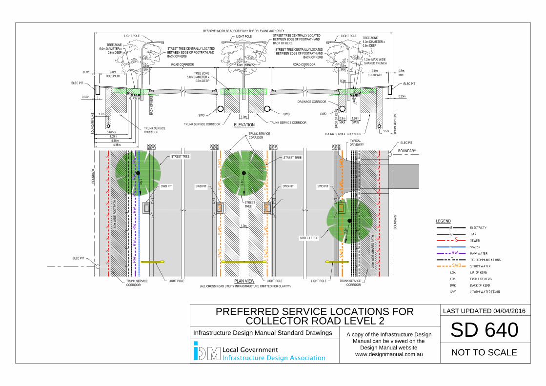
MIN
BOUN
DARY
LINE BA
CK O
F KE
RB
1.5m BOUN
DARY
LINE
BACK
OF
KERB
RESERVE WIDTH AS SPECIFIED BY THE RELEVANT AUTHORITY
SS
SWD
SWD
SWD
SWD
SWD
LOK
FOK
BOK
LOK
FOK
BOK
SS
SS
SS
SS
SS
PLAN VIEW(ALL CROSS ROAD UTILITY INFRASTRUCTURE OMITTED FOR CLARITY)
BOUN
DARY
LOK
FOK
BOK
BOUN
DARY
FOK
LOK
BOK
ELEVATION
SWD
SWD
SWD
SWD
SWD
MAX0.9m
0.3m
2.5m
2.5m
RWRW
RWRW
RWRW
RWW
WW
WW
WW
WW
WW
WW
WW
WW
WW
WW
WW
WW
WW
WW
WW
WW
WW
WW
WW
WW
WW
WW
WW
WW
WW
WW
WW
WW
WW
WW
WW
WW
WW
WW
WW
SS
SS
SS
SS
SS
EE
EE
EE
EE
EE
EE
EE
EE
EE
EE
EE
EE
EE
EE
EE
EE
EE
EE
EE
EE
EE
EE
EE
EE
EE
EE
EE
EE
EE
EE
EE
EE
EE
EE
EE
E
EE
EE
EE
EE
EE
EE
EE
EE
EE
EE
EE
EE
EE
EE
EE
EE
EE
EE
EE
EE
EE
EE
EE
EE
EE
EE
EE
EE
EE
EE
EE
EE
EE
EE
EE
E
EE
EE
EE
EE
EE
EE
EE
EE
EE
EE
EE
EE
EE
EE
EE
EE
EE
EE
EE
EE
EE
EE
EE
EE
EE
EE
EE
EE
EE
EE
EE
EE
EE
EE
EE
E
EE
EE
EE
EE
EE
EE
EE
EE
EE
EE
EE
EE
EE
EE
EE
EE
EE
EE
EE
EE
EE
EE
EE
EE
EE
EE
EE
EE
EE
EE
EE
EE
EE
EE
EE
E
SWD
SWD
SWD
SWD
SWD
SWD
SWD
SWD
SWD
SWD
3.675m4.05m
2.5m
T
MINROAD CORRIDOR ROAD CORRIDOR
1.0m
6.0m (MIN)0.8m
GG
GG
GG
GG
GG
GG
GG
GG
GG
GG
GG
GG
GG
GG
GG
GG
GG
GG
GG
GG
GG
GG
GG
GG
GG
GG
GG
GG
GG
GG
GG
GG
GG
GG
GG
G
1.0m3.0m
WID
E FO
OTPA
TH
GT
W
4.45m4.85m
RW
0.5m 3.0m
0.35m
1.5m
FOOTPATH0.5m
0.35m
FOOTPATH MIN
1.20m(MAX)
E
3.0m0.8m
2.5m
WID
E SH
ARED
PAT
H
STREETTREE
LEGEND
G
S
E
W
RW
SWD
BOUNDARY
STREET TREE CENTRALLY LOCATEDBETWEEN EDGE OF FOOTPATH ANDBACK OF KERB
ELEC PIT
1.2m (MAX) WIDESHARED TRENCH
TREE ZONE5.0m DIAMETER x0.6m DEEP
TRUNK SERVICE CORRIDOR
STREET TREE
TYPICALDRIVEWAY
STREET TREE CENTRALLY LOCATEDBETWEEN EDGE OF FOOTPATH ANDBACK OF KERB
STREET TREE CENTRALLY LOCATEDBETWEEN EDGE OF FOOTPATH AND
BACK OF KERB
LIGHT POLELIGHT POLELIGHT POLE
TRUNK SERVICE CORRIDOR TRUNK SERVICE CORRIDOR
TREE ZONE5.0m DIAMETER x
0.6m DEEP
SWDSWD SWD
DRAINAGE CORRIDOR
ELEC PIT
ELEC PIT
ELEC PIT
TRUNK SERVICECORRIDOR
TRUNK SERVICECORRIDOR
TRUNK SERVICECORRIDOR
LIGHT POLE LIGHT POLE LIGHT POLE
SWD PIT SWD PITSWD PIT SWD PIT
STREET TREE STREET TREE
TREE ZONE5.0m DIAMETER x
0.6m DEEP
TRUNK SERVICECORRIDOR
PREFERRED SERVICE LOCATIONS FOR
COLLECTOR ROAD LEVEL 2
SD 640
NOT TO SCALE
LAST UPDATED 04/04/2016
Infrastructure Design Manual Standard Drawings
A copy of the Infrastructure Design
Manual can be viewed on the
Design Manual website
www.designmanual.com.au
Local GovernmentInfrastructure Design Association

DESIGN ENGINEER’S CHECKLIST #D1 –REQUEST FOR FUNCTIONAL LAYOUT APPROVAL
DEVELOPMENT TITLE STAGE
PLANNING PERMIT NUMBER
CONSULTANT’S REFERENCE
DEVELOPER’S REPRESENTATIVE
NUMBER OF PLANS IN SET
CHECKLIST #D1
ITEM Y / N / NA OR COMMENT
DESIGNER’S INITIALS
General
Is th e de sign is in accordance with the planning permit conditions and th e endorsed plan?
Do other planning permits affect this development? (if yes, list permit numbers)
Is the design in accordance with the Development Plan?
Is the funct ional design is in accordance with Council’s Inf rastructure Design Manual?
Has c onsultation tak en pl ace wit h al l rel evant a uthorities? If yes, list th e authorities below.(attach separate list if necessary).
Has c onsultation h as tak en pl ace w ith a ll relevant la ndowners a nd affected persons? List those consulted below (attach separate list if necessary).
Has the Design Engineer has inspected the site?
Has a detailed field survey has been undertaken of the site?
Has the environmental values of the site have been identified?
Has protection of nat ive v egetation and habitat b een c onsidered a nd is it reflected in lot layout and overall design?
Has revegetation requirements been considered and documented?

CHECKLIST #D1
ITEM Y / N / NA OR COMMENT
DESIGNER’S INITIALS
Has protection of water bodies and waterways been considered?
Have service location plans been obtained for ALL services?
Do th e plan s clea rly sh ow allo tment la yout, with a llotments n umbered a nd dimensioned, reserves clearly identified and proposed easements shown?
Road Layout Plans
Are street names are nominated?
Do plans show road hierarchy?
Are estimated traffic volumes shown on plans (for each stage of any staged developments).
Have road widths between inverts of kerbs are nominated?
Are road reserve widths clearly nominated on plans?
Are kerb profiles are nominated?
Have public transport, including DOT, requirements been reflected in the road widths?
Has local area traffic management been considered and reflected in proposed designs?
Intersections internal to the deve lopment are sh own in sufficie nt d etail to support proposed design, including proposed kerb radii.
Are int ersections exter nal to the dev elopment sh own in sufficient deta il to support proposed design?
Are cr itical v ehicle t urning movements s hown o n s eparate plans, i ncluding turning at intersections and cul-de-sacs?
Do plans show traffic implications of staged development if relevant?
Carpark Layout Plans
Do c arpark l ayout plan s how o n-street, off-street a nd d isabled p arking a s required?
Drainage Layout Plans
Has the total catchment area has been identified and shown?
Do the plans show Natural Surface Contour Lines to AHD?

CHECKLIST #D1
ITEM Y / N / NA OR COMMENT
DESIGNER’S INITIALS
Are 100 year ARI flood levels identified on plans?
Do plans show approximate Design Contour Lines to AHD?
Are proposed sub-catchment boundaries shown on drainage layout plan?
Do plans show the co-efficient of runoff for each sub-catchment?
Do plans s hown l ayout and ap proximate sizes of th e p roposed drainage systems?
Are pipe materials nominated?
Has the over land flow path/s been nominated and approximate depth of fl ow shown?
Is the drainage discharge point shown?
Is the proposed treatment shown in suffic ient detail to support approval of the functional layout?
Are exist ing dr ainage services confirmed on plans a nd pr oposed co nnection points shown?
If relevant, do plans show drainage implications of staged development?
Associated Documents
Has a Traffic Management Report been prepared and does it accompany this submission?
Has any deviations between the pr oposed des ign and the recommendations within the Traffic Management Report been noted on the plan?
Has the need for Developer contributions or headworks charges been identified and a preliminary cost-sharing proposal to Council for early consideration been supplied?
The plans provided with this submission for approval of functional layout have been prepared in accordance with the relevant sections of the Council’s Manual. All of the above checklist items have been initialled as correct and complete, or marked N/A (not applicable) as appropriate.
Signed Dated
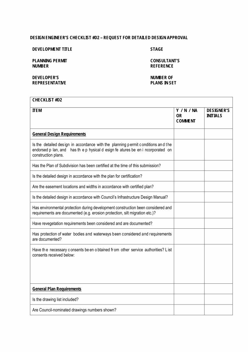
DESIGN ENGINEER’S CHECKLIST #D2 – REQUEST FOR DETAILED DESIGN APPROVAL
DEVELOPMENT TITLE STAGE
PLANNING PERMIT NUMBER
CONSULTANT’S REFERENCE
DEVELOPER’S REPRESENTATIVE
NUMBER OF PLANS IN SET
CHECKLIST #D2
ITEM Y / N / NA OR COMMENT
DESIGNER’S INITIALS
General Design Requirements
Is the detailed des ign in accordance with the planning p ermit c onditions an d t he endorsed p lan, and has th e p hysical d esign fe atures be en i ncorporated on construction plans.
Has the Plan of Subdivision has been certified at the time of this submission?
Is the detailed design in accordance with the plan for certification?
Are the easement locations and widths in accordance with certified plan?
Is the detailed design in accordance with Council’s Infrastructure Design Manual?
Has environmental protection during development construction been considered and requirements are documented (e.g. erosion protection, silt migration etc.)?
Have revegetation requirements been considered and are documented?
Has protection of water bodies and waterways been considered and requirements are documented?
Have th e necessary c onsents be en o btained fr om other service authorities? L ist consents received below:
General Plan Requirements
Is the drawing list included?
Are Council-nominated drawings numbers shown?

CHECKLIST #D2
ITEM Y / N / NA OR COMMENT
DESIGNER’S INITIALS
Is there a locality plan included?
Is the north arrow shown on all layout plans and detailed plans (should be shown up or to left).
Do all plans have correct scales shown?
Do all plans have comprehensive legends?
Do plans include standard notes? Are they applicable and clear?
Do p lans cl early sh ow al lotment l ayout, num bered al lotments, a ll di mensions, reserves and easements?
Is the limit of works shown on all layout plans?
Are all dams, wells, depressions and watercourses and fill requirements identified?
Are existing fill areas shown?
Are existing features and structures shown?
Are existing service locations and poles shown?
Are existing trees shown? Does the design attempt to retain trees?
Is existing native vegetation shown and suitably specified? Does design attempt to retain significant native vegetation?
Road Layout Plans
Is the datum shown to AHD?
Are scales in accordance with the Manual requirements?
Are PSM's and TBM's marked on the plans?
Are proposed service locations and offsets tabulated?
Are all required service conduit locations are indicated on the plans?
Are footpaths a minimum width of 1.5 m and located at correct offset?
Are shared paths minimum width of 2.5 m, and is their location clearly shown?
Are kerb crossings at appropriate locations and fully documented?
Are vehicle crossings shown on plans?

CHECKLIST #D2
ITEM Y / N / NA OR COMMENT
DESIGNER’S INITIALS
Do all vehicle crossings cater for a standard car?
Are any crossings located over easements?
Are any crossings located closer than 9m to the intersection?
Have all turning movements been checked and intersections designed accordingly?
Are street names acceptable to Council shown on plans?
Are road widths between inverts of kerbs nominated?
Are kerb profiles nominated?
Are road chainages shown?
Street Name Signage, Linemarking, and Traffic Control Plans
Are the locations and type of all new signage complying with the Australian Standards shown on plans?.
Is any existing signage to be removed or relocated shown on plans?
Are the locations and type of all li nemarking complying w ith Australian Standards shown on plans?
Is any existing linemarking to be removed shown on plans?
Are traffic calming devices designed and documented in accordance with Austroads “Guide to Road Design” and any VicRoads supplement to those guidelines, with the Manual, and with the accepted functional layout plan?
Does the limit of works of roads include temporary turning area if required?
Has the necessary ‘No Road’ signage or hazard markers been provided?
Road Longitudinal Sections
Are road names shown on longitudinal sections?
Are scales in accordance with the Manual requirements?
Is the Datum RL to AHD shown?
Are natural surface profile and levels shown at crown?
Are design surface profile and levels shown at crown?

CHECKLIST #D2
ITEM Y / N / NA OR COMMENT
DESIGNER’S INITIALS
Have levels b een checked by Design Engineer, do they comply with Manual, and match into existing surfaces?
Is depth of cut/fill to crown shown?
Are design surface profile and levels shown at left and right back of kerb (including high and low points)?
Are grades as + or – percent to tw o (2) decimal places sh own i n d irection of chainages?
Have grades been checked by Design Engineer, and do they comply with Manual, and match into existing grades. Min. grade = % Max. grade = % Match existing?
Are all vertical curve lengths and I.P values shown?
Are vertical curve levels shown at maximum intervals of 10 metres?
Are minimum kerb grades achieved?
Have levels a nd gra des given on lo ng sections b een che cked by the Design Engineer?
Do levels and grades match into existing abutting roadworks?
Is the minimum length of vertical curve for >1% grade change, 15 m (except on kerb returns).
Does the external road grading for future stages extend a minimum of 100 metres beyond the limit of works?
Does the vertical curves and longitudinal grades provide satisfactory sight distances for standard roads, particularly at intersections?
Has the coordination of ve rtical and horizontal curves provided a desirable design outcome?
Road Cross-Sections
Has th e Des ign En gineer checked that cross-s ections agre e with l ongitudinal sections?

CHECKLIST #D2
ITEM Y / N / NA OR COMMENT
DESIGNER’S INITIALS
Is the datum is shown on every cross-section?
Do scales comply with the Manual?
Are road names and chainage references shown?
Are natural and design levels given at:
Back of kerb?
Lip of kerb?
Crown?
Property lines?
Front of footpath?
Table drain inverts (where applicable)?
Top and toe of batters (where applicable)?
Are all pavement, nature strip, footpath and batter crossfalls in accordance with the Manual?
Typical Cross-Sections and Traffic/Road Details
Are typical cross-sections presented in accordance with the ‘Information to be Shown on Plans’ requirements of the Manual?
Are road name and chainage references noted, if applicable?
Are profile and geometry of design surface grades shown as % or 1 in X and comply with Manual requirements?
Are details of road pavement construction, including materials, compaction and type of seal shown?
Are details of footpath construction, including materials, compaction and seal shown, or is the relevant standard drawing noted?
Are typical alignment of services, subsoil drainage and landscaping shown?
Are kerb and channel types are nominated?
Is kerb and channel construction detailed or standard drawings noted?

CHECKLIST #D2
ITEM Y / N / NA OR COMMENT
DESIGNER’S INITIALS
Intersection, Court and Curve Details
Are road names shown?
Are road chainages shown?
Are intersection details shown at correct scales in accordance with Manual?
Are at least four kerb levels given on every kerb radial?
Do tangent point levels and chainages align with longitudinal and cross sections?
Are set-out details shown including angle, radii and tangent points?
Are design Surface contours shown to AHD at 50 mm maximum intervals?
Are back of kerb levels shown to AHD?
Are footpath levels shown?
Are locations of low points shown?
Are services (including drainage) shown in detail?
Is landscaping shown in detail?
Are footpath and kerb crossings shown in detail?
Drainage Layout Plans
Has the Design Engineer checked that drainage design in accordance with AR&R?
Is the datum shown to AHD?
Are scales in accordance with the Manual requirements?
Are PSM's and TBM's marked on plans to AHD?
Are finished surface levels shown where the natural surface is altered?
Do plan s clea rly show a llotment la yout, n umbered allo tments, re serves an d easements?
Are 1 in 100 year flood levels shown?
Are road names shown?

CHECKLIST #D2
ITEM Y / N / NA OR COMMENT
DESIGNER’S INITIALS
Do plans show la yout of p roposed drainage s ystems wi th offset fr om pro perty boundaries?
Are pipe materials and diameters shown?
Are all concrete pipes RRJ only?
Do all non-concrete pipes have Council acceptance?
For all non-concrete pipes is there a note on the plan stating that all bedding, laying, jointing and backfilling is to be in accordance with manufacturer’s specifications?
Is the overland flow path accepted by Council shown?
Is the kerb and channel and footpath depressed where the overland flow path leaves the road pavement?
Are subsurface drains, house drains and property inlets shown?
Are pits at appropriate locations (e.g. away from kerb returns, vehicle crossings, kerb crossings etc.)?
Is the maximum pit spacing 80m?
Has the pit capacity checked by the Design Engineer?
Are double SEP’s confined to low points only?
Are all changes in angle not greater than 90o?
Are all pits/headwalls numbered?
Is the set-out point of pits clearly shown on legend?
Do footpath spoon drains have adequate outfall?
Has back of kerb drainage (e.g. roundabout kerbs) adequate outfall?
Are ex isting fe nces, bui ldings, trees an d ob structions s hown i n pat h of over land flows?
Are all proposed fences, buildings, trees and obstructions shown in path of overland flows?
Are existing or pr oposed open e arth dr ains, da ms, w atercourses, boreholes, s ink holes, wells and springs within the area shown?
Is the extent of required erosion protection at headwalls and other structures shown?

CHECKLIST #D2
ITEM Y / N / NA OR COMMENT
DESIGNER’S INITIALS
Are the details of all drop structures required shown?
Do all properties have identified drainage discharge points (to underground drainage systems for industrial and c ommercial de velopments, and residential wherever possible)?
Drainage Longitudinal Sections
Have longitudinal sections been prepared for all legs of dra inage, open drains, and nominated overland flow paths?
Are scales in accordance with the Manual requirements?
Is there a comprehensive legend shown?
Is datum RL to AHD shown?
Are drainage line numbers names shown on longitudinal sections?
Are drainage line chainages shown on longitudinal sections?
Do any lengths of drainage sections exceed the maximum permitted of 80 metres?
Is the pipe diameter, class and grade shown for all legs of drainage?
Have pipe classes been determined with consideration to construction loads and final cover?
Has a cross-check with compaction requirements in documentation been carried out?
Do pipes with steep grades include anchor blocks?
Is pit number and pit type shown?
Do pit type match capacity requirements?
Are any special pits fully documented?
Are internal pit dimensions shown?
Are pit inlet and outlet levels shown?
Are depths of pits to invert levels shown?
Are finished top of pit levels and finished surface level adjacent to pits shown?
Are pit lid type and class shown?

CHECKLIST #D2
ITEM Y / N / NA OR COMMENT
DESIGNER’S INITIALS
Are origin/destination pits for inlet and outlets shown?
Are junction line numbers noted?
Are design pipes plotted on longitudinal section?
Is the hydraulic grade line plotted and levels given?
Is the depth x flow factor acceptable?
Has the minimum 150mm freeboard to kerb invert been achieved for minor storms?
Have all the energy losses in drainage system been accounted for?
Has all crosses with other services been plotted and clearances nominated (street names should be referred to identify crossings)?
Are design flows shown in litres/second?
Are design velocities, complying with the manual shown (metres/second)?
Is FCR backfill specified under road pavements, footpaths, crossovers and building lines?
Has the location and type of special backfill requirements been noted (e.g. to prevent piping of backfill material)?
Is the design in accordance with AS3725 and its commentary?
Open Drains
Is the shape of drain suitable for maintenance?
Is the drain accessible from both sides and all-weather tracks provided?
Is the depth of floodways shown on cross-sections? Is the depth less than 1.5 metres?
Were scour velocities and siltation both checked in determining longitudinal grades?
Are grade control / drop structures fully documented?
Has the low-flow pipe been provided in accordance with the Manual?
Are outfall structures energy dissipators provided as required?
Has the 300mm minimum freeboard been achieved?

CHECKLIST #D2
ITEM Y / N / NA OR COMMENT
DESIGNER’S INITIALS
Detail Plans
Non-standard drainage structures are fully detailed for construction - headwalls - drop structures - er osion pr otection at outl et structures - erosion pr otection fo r batter s where needed.
Non-standard pits are fully documented including reinforcement and pit lid details.
Structural details of all retaining walls are shown, as well as details of natural surface levels and design surface levels, foundation requirements, drainage requirements, and type of finish.
Details of street furniture.
Drainage pump stations fully documented.
Layout and details of power installation documented.
Details of any estate entrance structures, including structural details, location details and method of finish.
Traffic calming devices are fully detailed to ensure construction is in accordance with design re quirements (e .g. sp litter island s, ch icanes, spe ed humps, ro undabout construction).
Lotfilling Plans
Are natural surface contours shown with 50 mm maximum intervals?
Are design surface contours shown with 50 mm maximum intervals?
Are finished surface levels shown? Do all allotments have minimum 1 in 200 grade toward low point?
Are 1%AEP flood levels shown on plans? Are all lots to be filled above this level?
Is proposed fill in excess of 300mm clearly denoted on plans?
Are m aterial and compaction req uirements, com plying with th e r elevant Austr alianStandard, fully documented in the plans and specifications?
Is the extent of lotfilling, top and toe of batters and retaining walls all noted?
Drainage Retardation and Treatment
Are computations provided to verify the volume of the basin?

CHECKLIST #D2
ITEM Y / N / NA OR COMMENT
DESIGNER’S INITIALS
Is erosion protection fully documented?
Are inlet structures fully documented?
Is the overflow identified and appropriate?
Has the minimum freeboard been achieved?
Do wetland plantings have alternative source of water for establishing plants and for periodic dry spells?
Master Services Plans
Do plans show numbered allotments, road reserves and road carriageways?
Are street light types nominated for acceptance?
Are A LL u nderground s ervice al ignments shown, i ncluding no n-essential services such as gas, raw water and irrigation lines, fire hydrants, fire plugs and street trees?
Are A LL major ab oveground features s hown such as str eet lights, power supply pillars, fencing, street trees, and landscaping etc?
Landscaping Plans
Is detailed irrigation layout plans provided showing valves, controllers, pipe material and sizes, alignments, nozzle details, and backflow devices?
Is the planting schedule included, including size of plants?
Is the location of major plantings clearly shown?
Are pl anting requirements d ocumented including dim ension of hole, root barrier, backfill, mulch, stakes, tree grates, tree guards, and stakes?
Is street furniture detailed including type, colour, location and installation?
Associated Documents
If required, was a TMAR prepared and accompanies this submission?
If required, was a TIAR prepared and accompanies this submission?
If requ ired, w as a Road S afety A udit R eport pr epared a nd accompanies th is submission?
Is there a no te provided for any deviations between the proposed design and the recommendations within the Road Safety Audit report?

CHECKLIST #D2
ITEM Y / N / NA OR COMMENT
DESIGNER’S INITIALS
Are hydrological calculations provided for whole of catchment and partial areas if relevant, and 100yr ARI design flows calculated at critical points? (Method nominated and assumptions clearly stated ARI’s in accordance with Manual.)
Are hydraulic calculations provided for above and underground drainage, for major and mino r storm e vents. (Me thod no minated a nd assumptions c learly stat ed. Roughness coefficients nominated)?
Has there been a copy of geotechnical reports provided with the submission?
Is the road pavement design provided with the submission?
Are quality assurance sections included in the specification?
Is a risk assessment r eport provi ded f or dra inage ret ardation and treatment Infrastructure?
Are operation and maintenance (O&M) manuals provided with this submission?
Are structural computations provided, where applicable, with this submission?
The plans, specifications and associated documents provided with this submission for detailed design approval have been prepared in accordance with the relevant sections of Council’s Manual. All of the above checklist items have been initialled as correct and complete, or marked N/A (not applicable) as appropriate.
Signed _____________________________________ Dated

DESIGN ENGINEER’S CHECKLIST #D3 – REQUEST FOR FINAL DESIGN APPROVAL
DEVELOPMENT TITLE STAGE
PLANNING PERMIT NUMBER
CONSULTANT’S REFERENCE
DEVELOPER’S REPRESENTATIVE
NUMBER OF PLANS IN SET
CHECKLIST #D3
ITEM Y / N / NA OR COMMENT
DESIGNER’S INITIALS
General
Has detailed design approval been received from Council – if so note date?
Is the final design is in accordance with the planning permit conditions and the endorsed p lan, an d p hysical design fe atures inc orporated on c onstruction plans?
Has the plan of subdivision been certified at the time of this submission?
Have the appropriate consents been obtained from service authorities? List any consents received below:
25.3 25.4 25.5
Plans
Do th e fin al plans r eflect am endments r equired by C ouncil u nder previous reviews?
Other
Is the Engineer’s estimate provided with this submission?
Are separate streetscaping and/or landscaping plans included?
The plans, specifications and associated documents provided with this submission for final design approval have been prepared in accordance with the relevant sections of the Council’s Manual. All of the above checklist items have been initialled as correct and complete, or marked N/A (not applicable) as appropriate.
Signed _____________________________________ Dated

DESIGN ENGINEER’S FORM #D4 – INTENTION TO COMMENCE CONSTRUCTION Notice is given that the construction of the development detailed below is due to commence.
NAME OF COUNCIL TO WHOM NOTICE IS GIVEN
DEVELOPMENT TITLE STAGE
PLANNING PERMIT NUMBER
CONSULTANT’S REFERENCE
DESIGNER WORKS WITHIN ROAD RESERVE PERMIT NUMBER
DEVELOPER’S REPRESENTATIVE
CONSTRUCTION ENGINEER
CONTRACTOR CONTRACTOR’S NOMINATED REPRESENTATIVE ON SITE
OTHER RELATED PARTIES INCLUDE
PROPOSED DATE OF THE COMMENCEMENT OF WORKS
The following documentation accompanies this notice:
Construction Program.
Inspection and Test Plans.
Signed _____________________________________ Dated

CONSTRUCTION ENGINEER’S CHECKLIST #D5 – REQUEST FOR ACCEPTANCE OF WORKS INSPECTION
DEVELOPMENT TITLE STAGE
PLANNING PERMIT NUMBER
DEVELOPER’S REPRESENTATIVE
CHECKLIST #D5
THE FOLLOWING ITEMS HAVE BEEN COMPLETED Y / N / NA OR COMMENT
CONSTRUCTION ENGINEER’S INITIALS
Are all road construction works complete?
Are signs in place in accordance with the approval plans?
Is linemarking complete?
Are all drainage works complete, clean and ready for inspection?
Are fencing works complete if required?
Have pump stations been commissioned or are ready to be commissioned at the Acceptance of Works i nspection? (N ote th at O&M m anuals are to be provided one week prior to commissioning, draft manuals are acceptable).
Are footpaths and kerb crossings complete?
Are nature strips reinstated and in a tidy manner?
Are all earthworks at the site completed?
Have fire hy drants and fire plugs been installed and marked in accordance with fire authority’s requirements?
Are erosion protection works complete?
Are litter traps complete?
Is street lighting complete?
Is landscaping complete?
Have streets been swept?
Have i nstallation dates for any major traffi c control items been provided to Council?
All construction works should be complete prior to calling for an Acceptance of Works inspection. Any outstanding works should be noted below:
An Acceptance of Works inspection is requested of Council. Proposed date and time:
Signed _____________________________________ Dated
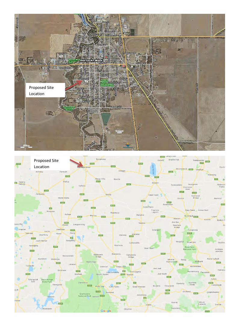
Proposed Site
Location
Proposed Site
Location
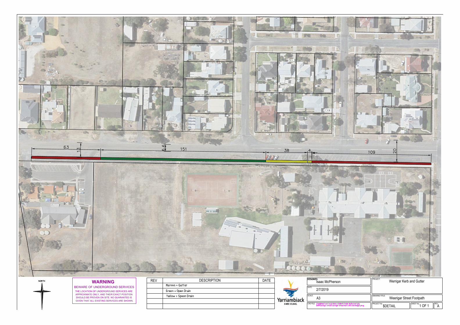
DATEWARNINGBEWARE OF UNDERGROUND SERVICES
THE LOCATION OF UNDERGROUND SERVICES ARE
APPROXIMATE ONLY, AND THEIR EXACT POSITION
SHOULD BE PROVEN ON SITE. NO GUARANTEE IS
GIVEN THAT ALL EXISTING SERVICES ARE SHOWN.
PROJECT No. SHEET No.$DETAIL
REV:1 OF 1
Werrigar Kerb and GutterDESCRIPTIONREVDATE:
SCALE:
CAD FILE:
2/7/2019
Isaac McPherson
A3
A
PROJECT:
Weerigar Street FootpathDRAWING TITLE:
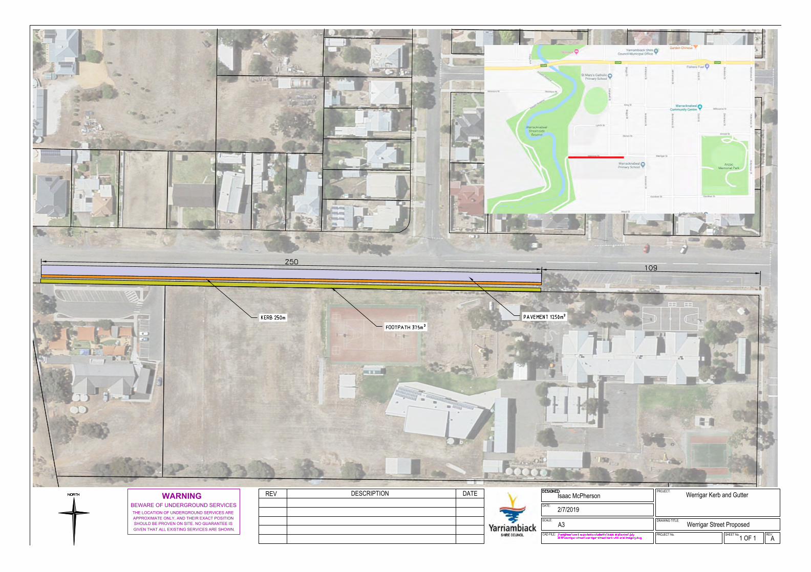
DATEWARNINGBEWARE OF UNDERGROUND SERVICES
THE LOCATION OF UNDERGROUND SERVICES ARE
APPROXIMATE ONLY, AND THEIR EXACT POSITION
SHOULD BE PROVEN ON SITE. NO GUARANTEE IS
GIVEN THAT ALL EXISTING SERVICES ARE SHOWN.
PROJECT No. SHEET No. REV:1 OF 1
Werrigar Kerb and GutterDESCRIPTIONREVDATE:
SCALE:
CAD FILE:
2/7/2019
Isaac McPherson
A3
A
PROJECT:
Werrigar Street ProposedDRAWING TITLE: