request for quotes city of delano central park concessions
TRANSCRIPT
Request for Quotes City of Delano
Central Park Concessions Building Project
The City of Delano is accepting quotes for work on the Central Park Concessions Building Project. Contractors interested in providing a quote shall do so in conformance with the terms and conditions outlined within this document.
Insulation Services
Quote Submission Deadline: December 21, 2017 – 2:00pm Acceptable Submission Methods: Delivery to Delano City Hall or electronic PDF submission Quote Requirements:
1. All quotes shall include a statement confirming that this Request for Quotes and any attachments have been reviewed and terms are acceptable. Any changes, modifications, or additional conditions added by the Contractor will be reviewed by the City as part of the quote consideration process. The City reserves the right to reject any and all bids. Attachment 1 – Central Park Concessions Building Plan Set Attachment 2 – Truss plan Attachment 3 – Sample Contract for Services
2. Quote shall bid amounts for the following work:
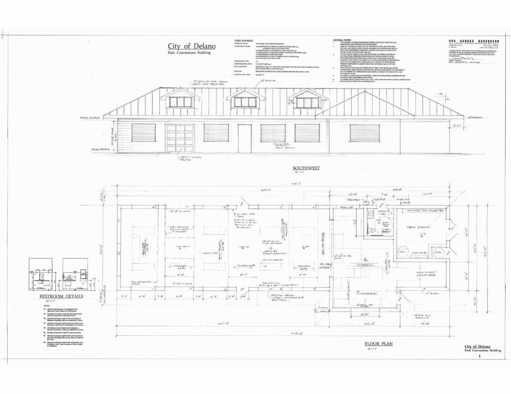
Part 1 – Provide all materials and labor to complete installation of insulation of the roof and ceiling throughout the building. Note the kitchen will have a standard ceiling and the multipurpose area will be a vaulted ceiling. Contractor shall bid according to the following specifications:
1. Minimum of R-49 blown insulation in attic 2. Minimum of R-21 batt dormer walls 3. Supply and install Poly – sealed to Code 4. Supply and install vent chutes 5. Contractor to supply netting and rulers as needed
Part 2 – Provide an hourly rate for additional services needed through construction (materials, if needed, would be added to a contract by change order).
3. The City is performing the role of general contractor. Work will be coordinated by the City
Administrator and additional direction may be provided other members of the City’s team, depending on the part of the project.

4. The City will review all quotes promptly following the submission deadline, and reserves the right to amend the deadline as needed based on construction conditions. The City intends to take action on quotes within 30 days, but may from time-to-time delay action at its discretion. Contractor shall state any timing conditions, if needed, within the quote document.
City Contact: Phil Kern, City Administrator [email protected] 763-972-0565


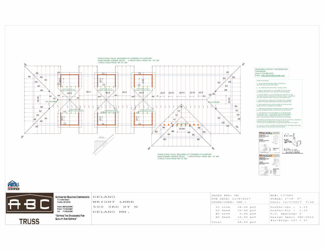
DESIGNER CONTACT INFORMATION:TOM EBLERDirect # 715 895-9749Email: [email protected]
ROOF PLAN NOTES:
1. TRUSS IDENTIFICATION LABEL LOCATED ONBOTTOM SIDE OF BOTTOM CHORD
2. ALL DIMENSIONS ARE IN FEET- INCHES-16THS
3. END OF TRUSS WITH "X" TICK MARK ON THE LAYOUTCORRESPONDS WITH LEFT END ON TRUSS DRAWING.
4. DO NOT MODIFY, CUT, OR REPAIR ANY PORTION OF THETRUSSES WITHOUT APPROVAL FROM ABC TRUSS. WARRANTYWILL BE VOIDED WITHOUT OFFICIAL DOCUMENTATION.
5. SEE INDIVIDUAL TRUSS CALC FOR MULTI-PLY GIRDERCONNECTION AND PERMANENT BRACING INFORMATION
6. SEE HANGER INSTALLATION GUIDE OR CATALOG FOR MORE DETAIL ON HANGER ATTACHMENT.
7. TEMPORARY BRACING INFORMATION IS SHOWN ON THEBCSI-B1 SUMMARY SHEET LOCATED IN THE JOB PACKET.
8. THE INTENT OF THIS DOCUMENT IS TO SHOW TRUSS PLACEMENT ONLY. THE CONTRACTOR IS RESPONSIBLEFOR VERIFYING ALL DIMENSIONS AND WALL HEIGHTSWITH THE BLUEPRINT PRIOR TO SETTING THE TRUSSES.
9. BEARINGS DESIGNED FOR A FcPerp VALUE OF 425 FOR ALL BEARINGS. (UNLESS NOTED OTHERWISE BY A FcPerp ### NOTE)"TOP PLATE OF BEARING WALL DESIGN AND MATERIAL BY OTHERS."
10. SET ALL VALLEY TRUSSES AFTER MAIN ROOF HAS BEEN SHEATHED. ADJUSTMENT OF SPACING MAY BE REQUIRED.
STRUCTURAL FACIA REQUIRED AT CORNERS TO SUPPORT HAND FRAME CORNER JACKS . 1 PIECE FACIA FROM ''A2'' TO ''AR'' 1 PIECE FACIA FROM ''AR TO ''AB''
STRUCTURAL FACIA REQUIRED AT CORNERS TO SUPPORT HAND FRAME CORNER JACKS . 1 PIECE FACIA FROM ''BB'' TO ''BR'' 1 PIECE FACIA FROM ''BR TO ''BD''
XB LAYOVER
XA LAYOVER XA LAYOVER
HANDFRAME VALLEY(design & material by others)
HANDFRAME VALLEY(design & material by others)
HANDFRAME VALLEY(design & material by others)
HANDFRAME VALLEY(design & material by others)HANDFRAME VALLEY
(design & material by others)
HANDFRAME VALLEY(design & material by others)
SALES REP: CM
DUE DATE: 11/8/2017
DSGNR/CHKR: TRE /
TC Live
TC Dead
BC Live
BC Dead
Total
38.50 psf
10.00 psf
0.00 psf
10.00 psf
58.50 psf
WO#: t77483
SCALE: 1"=9' 0"
Date: 12/7/2017 7:34
DurFac-Lbr : 1.15
DurFac-Plt : 1.15
O.C. Spacing: 2
Design Spec: IBC-2012
#Tr/#Cfg: 127 / 37
DELANO
WRIGHT LMBR
500 3RD ST N
DELANO MN.
B
BR BR
BBBC
BD
BBBC
BD
BD
BE
BD
BE
E1
2-0
2-0
2-0
2-0
2-0
2-0
2-0
2-0
2-0
2-0
2-0
2-0
A
2-0
A4
1-8-
12
A4
0-1-
12
1-10
-42-0
2-0
2-0
A4
1-0-
12
A41-
5-12
0-6-
42-0
2-0
2-0
2-0
A4
0-4-
12
A4
A
2-0
A1
2-0
A2
7-11
-4
E2
2-0
E3
7-11
-4
AR
AR
AB
AC
AD
AE
AB
AC
AD
AE ACAD
AE
ACAD
AE
EB
EB
ER
EREC
ED
EE
EC
ED
EE
EC
ED
EE
EC
EDEE
C1
C2
C1
C2
C1
C2
C1
C2
C1
C2
C1
C2
1-7-
42-0
2-0
0-11
-42-0
2-0
2-0
2-3-
42-0
2-0
2-0
V1
V2
V3
V4
(3) E
A
(4) D(4) D(4) D
(2) C
(2) C
(3) A
A
(5) A
(2) C
(4) A
(2) C
(2) C
(2) C
(3) BA
(2) E (2) F1 (3) F2 (2) F1 (2) E

Dsgnr: TRE
Chk:
TC Live 38.50 psf
TC Dead 10.00 psf
BC Live 0.00 psf
BC Dead 10.00 psf
TOTAL 58.50 psf
DurFacs L=1.15 P=1.15
Rep Mbr Bnd 1.15
O.C.Spacing 2- 0- 0
Design Spec IBC-2012
Seqn T6.5.20 - 252796
12/ 7/2017
Work Order: t77483 Customer: WRIGHT LMBR
Job Name: DELANO
Truss ID: A Qty: 11 Desc: PCT
WARNING Read all notes on this sheet and give a copy of it to the Erecting Contractor.This design is for an individual building component not truss system. It has been based on specifications provided by the component manufacturerand done in accordance with the current versions of TPI and AFPA design standards. No responsibility is assumed for dimensional accuracy. Dimensionsare to be verified by the component manufacturer and/or building designer prior to fabrication. The building designer must ascertain that the loadsutilized on this design meet or exceed the loading imposed by the local building code and the particular application. The component manufacturer is not thebuilding designer. The design assumes that the top chord is laterally braced by the roof or floor sheathing and the bottom chord is laterally braced by a rigidsheathing material directly attached, unless otherwise noted. Bracing shown is for lateral support of component members only to reduce buckling length. Thiscomponent shall not be placed in any environment that will cause the moisture content of the wood to exceed 19% and/or cause connector plate corrosion.Fabricate, handle, install and brace this truss in accordance with the following standards: 'Joint and Cutting Detail Reports' available as output from Truswalsoftware, 'ANSI/TPI 1', 'WTCA 1' - Wood Truss Council of America Standard Design Responsibilities, 'BUILDING COMPONENT SAFETY INFORMATION' -(BCSI) and 'BCSI SUMMARY SHEETS' by WTCA and TPI. The Truss Plate Institute (TPI) is located at 218 N. Lee Street Suite 312,Alexandria, VA 22314. The American Forest and Paper Association (AFPA) is located at 1111 19th Street, NW, Ste 800, Washington, DC 20036.
AUTOMATEDBUILDINGCOMPONENTS
A B C 1111 8TH STREETCHETEK, WI 54728PHONE: (800) 524-9990 FAX: (715) 924-2585
6.00 -6.00
6.00 -6.00
Scale: 1/8" = 1'
1 2 3 4 5 6 7
4-6-04-6-0
5-9-010-3-0
5-9-016-0-0
5-9-021-9-0
5-7-027-4-0
4-8-032-0-0
8 9 10 11 12 13 144-8-04-8-0
5-7-010-3-0
5-9-016-0-0
5-9-021-9-0
5-7-027-4-0
4-8-032-0-0
TYPICAL PLATE : 4X8
5X6
4X4
6X6
4X4
4X6
6X6
6X6
6X61.5X4
1.5X4
1.5X4
1.5X4
4-0-0 4-0-0
32-0-0
0-10-0
8-10-0
0-10-0
8-10-0
16-0-0 16-0-0
4-8-011-4-0
11-4-04-8-0
5-8-04-0-0 4-0-0
SHIP
BRG X-LOC REACT SIZE REQ'D 1 4- 4- 0 1963 8.00" 3.08" 2 27- 8- 0 1962 8.00" 3.08"
TC FORCE AXL BND CSI 1-2 527 0.08 0.49 0.57 2-3 -2444 0.03 0.48 0.51 3-4 -3252 0.08 0.70 0.78 4-5 -3252 0.08 0.70 0.78 5-6 -2444 0.03 0.48 0.51 6-7 527 0.08 0.49 0.57
BC FORCE AXL BND CSI 8-9 -402 0.00 0.16 0.16 9-10 -445 0.00 0.40 0.4010-11 2399 0.19 0.46 0.6511-12 2400 0.19 0.46 0.6512-13 -445 0.00 0.40 0.4013-14 -402 0.00 0.16 0.16
WEB FORCE CSI WEB FORCE CSI 2-9 -1659 0.62 2-10 2025 0.70 3-10 -1003 0.38 3-11 922 0.57 4-11 2262 0.90
5-11 922 0.57 5-12 -1003 0.38 6-12 2025 0.70 6-13 -1659 0.62
TC 2x4 SPF C1650F1.5EBC 2x6 SPF C1650F1.5E 2x4 SPF #1/#2-CAN 9-11, 11-13WEB 2x3 SPF #3-CAN 2x3 SPF #1/#2-CAN 2-10, 12-6 2x4 SPF #3-CAN 11-4WEDGE 2x6 SPF C1650F1.5E 2x4 SPF #1/#2-CAN 2GBL BLK 2x3 SPF #3-CANLumber shear allowables are per NDS.
Designed per ANSI/TPI 1-2007Fabrication Tolerance = 16.0%Bearings designed for an FcPerp value of the lesser of the truss chord lumber value or 425 for all bearings.Plating is based on quality control factors Cq = 0.84 for wide face and Cq = 0.94 for narrow face. Any alterations to this are shown for individual joints on the Joint Report.Kcr (creep factor) = 1.50Refer to Joint QC Detail Sheet for
Maximum Rotational Tolerance used THIS DESIGN IS THE COMPOSITE RESULT OF MULTIPLE LOAD CASES.IRC/IBC truss plate values are based on
testing and approval as required by IBC 1703and ANSI/TPI and are reported in availabledocuments as ER-1607 and ESR-1118.
Loaded for 10 PSF non-concurrent BCLL.Loaded for 200 lb non-concurrent moving BCLL.Heel plates analyzed for eccentricity.ASCE7-10 SNOW LOAD DESIGN CRITERIA:
Pg = 50 psf, Ce = 1.0, I = 1.0, Ct = 1.10 + + + + + + + + + + + + + + + + + + + + + +Unrestrained horiz. LL deflection = 0.31 "+ + + + + + + + + + + + + + + + + + + + + +
Gable verticals are 2x 3 web material spaced at 16.0 " o.c. unless noted otherwise.Top chord supports 24.0 " of uniform load at 39 psf live load and 10 psf dead load. Additional design considerations may be required if sheathing is attached.Brace gable studs in accordance with Truswal Systems standard gable bracing details and charts.This truss requires adequate sheathing, as designed by others, applied to the truss face providing lateral support for webs in the truss plane and creating shear wall action to resist diaphragm loads.
UPLIFT REACTION(S) :Support Main Wind Non-Wind 1 -159 lb 2 -159 lbThis truss is designed using theASCE7-10 Wind SpecificationBldg Enclosed = Yes,Truss Location = Not End ZoneExp Category = CBldg Length = 80.00 ft, Bldg Width = 40.00 ftMean roof height = 14.42 ft, mph = 115Occupancy Category II, Dead Load = 12.0 psfDesigned as Main Wind Force Resisting System - Low-rise and Components and CladdingTributary Area = 64 sqft 20 psf bottom chord live load NOT requiredon this truss, per IBC/IRC requirements forattics with limited storage.
MAX DEFLECTION (span) :L/745 MEM 3-4 (LIVE) LC 49L= -0.36" D= -0.16" T= -0.53"MAX DEFLECTION (cant) :L/342 MEM 13-14 (LIVE) LC 94L= 0.17" D= 0.02" T= 0.18"
===== Joint Locations ===== 1 0- 0- 0 8 0- 0- 0 2 4- 6- 0 9 4- 8- 0 3 10- 3- 0 10 10- 3- 0 4 16- 0- 0 11 16- 0- 0 5 21- 9- 0 12 21- 9- 0 6 27- 4- 0 13 27- 4- 0 7 32- 0- 0 14 32- 0- 0
All plates are 20 gauge Truswal Connectors unless preceded by "MX" for HS 20 gauge or "H" for 16 gauge, positioned per Joint Detail Reports available from Truswal software, unless noted.

Dsgnr: TRE
Chk:
TC Live 38.50 psf
TC Dead 10.00 psf
BC Live 0.00 psf
BC Dead 10.00 psf
TOTAL 58.50 psf
DurFacs L=1.15 P=1.15
Rep Mbr Bnd 1.10
O.C.Spacing 2- 0- 0
Design Spec IBC-2012
Seqn T6.5.20 - 252797
12/ 7/2017
Work Order: t77483 Customer: WRIGHT LMBR
Job Name: DELANO
Truss ID: A1 Qty: 1 Desc: PCT VAULT
WARNING Read all notes on this sheet and give a copy of it to the Erecting Contractor.This design is for an individual building component not truss system. It has been based on specifications provided by the component manufacturerand done in accordance with the current versions of TPI and AFPA design standards. No responsibility is assumed for dimensional accuracy. Dimensionsare to be verified by the component manufacturer and/or building designer prior to fabrication. The building designer must ascertain that the loadsutilized on this design meet or exceed the loading imposed by the local building code and the particular application. The component manufacturer is not thebuilding designer. The design assumes that the top chord is laterally braced by the roof or floor sheathing and the bottom chord is laterally braced by a rigidsheathing material directly attached, unless otherwise noted. Bracing shown is for lateral support of component members only to reduce buckling length. Thiscomponent shall not be placed in any environment that will cause the moisture content of the wood to exceed 19% and/or cause connector plate corrosion.Fabricate, handle, install and brace this truss in accordance with the following standards: 'Joint and Cutting Detail Reports' available as output from Truswalsoftware, 'ANSI/TPI 1', 'WTCA 1' - Wood Truss Council of America Standard Design Responsibilities, 'BUILDING COMPONENT SAFETY INFORMATION' -(BCSI) and 'BCSI SUMMARY SHEETS' by WTCA and TPI. The Truss Plate Institute (TPI) is located at 218 N. Lee Street Suite 312,Alexandria, VA 22314. The American Forest and Paper Association (AFPA) is located at 1111 19th Street, NW, Ste 800, Washington, DC 20036.
AUTOMATEDBUILDINGCOMPONENTS
A B C 1111 8TH STREETCHETEK, WI 54728PHONE: (800) 524-9990 FAX: (715) 924-2585
6.00 -6.00
6.00 -6.00
Scale: 1/8" = 1'
1 2 3 4 5 6 7 8
4-6-04-6-0
5-9-010-3-0
3-8-413-11-4
4-1-818-0-12
3-8-421-9-0
5-7-027-4-0
4-8-032-0-0
9 10 11 12 13 14 15 164-8-04-8-0
5-7-010-3-0
3-9-1214-0-12
3-10-817-11-4
3-9-1221-9-0
5-7-027-4-0
4-8-032-0-0
TYPICAL PLATE : 6X6
5X6
3X4
8X8 5X6
3X4
4X6
5X8 5X8
1.5X4
1.5X4
1.5X4
1.5X4
4-0-0 4-0-0
32-0-0
0-10-0
7-9-10
0-10-0
7-9-10
13-11-4 4-1-8 13-11-4
4-8-09-4-12
3-10-89-4-12
4-8-0
4-8-64-0-0 4-0-0
7-7-15
SHIP
BRG X-LOC REACT SIZE REQ'D 1 4- 4- 0 2095 8.00" 3.29" 2 27- 8- 0 2095 8.00" 3.29"
TC FORCE AXL BND CSI 1-2 516 0.10 0.84 0.94 2-3 -2453 0.06 0.65 0.71 3-4 -3082 0.10 0.43 0.53 4-5 -2796 0.16 0.48 0.64 5-6 -3088 0.10 0.43 0.53 6-7 -2451 0.06 0.65 0.71 7-8 516 0.10 0.84 0.94
BC FORCE AXL BND CSI 9-10 -394 0.00 0.16 0.1610-11 -463 0.00 0.43 0.4311-12 2367 0.47 0.09 0.5612-13 2789 0.57 0.05 0.6213-14 2367 0.47 0.08 0.5514-15 -463 0.00 0.43 0.4415-16 -394 0.00 0.16 0.16
WEB FORCE CSI WEB FORCE CSI 2-10 -1787 0.67 2-11 2091 0.72 3-11 -994 0.37 3-12 695 0.41 4-12 983 0.54 4-13 270 0.18
5-13 984 0.54 6-13 704 0.41 6-14 -996 0.37 7-14 2090 0.72 7-15 -1787 0.67
TC 2x4 SPF #1/#2-CANBC 2x4 SPF #1/#2-CAN 2x6 SPF C1650F1.5E 9-10, 15-16WEB 2x3 SPF #3-CAN 2x3 SPF #1/#2-CAN 2-11, 14-7WEDGE 2x6 SPF C1650F1.5E 2x4 SPF #1/#2-CAN 2GBL BLK 2x3 SPF #3-CANLumber shear allowables are per NDS.
Designed per ANSI/TPI 1-2007Fabrication Tolerance = 16.0%Bearings designed for an FcPerp value of the lesser of the truss chord lumber value or 425 for all bearings.Plating is based on quality control factors Cq = 0.84 for wide face and Cq = 0.94 for narrow face. Any alterations to this are shown for individual joints on the Joint Report.Kcr (creep factor) = 1.50Refer to Joint QC Detail Sheet for Maximum Rotational Tolerance used
THIS DESIGN IS THE COMPOSITE RESULT OF MULTIPLE LOAD CASES.
IRC/IBC truss plate values are based ontesting and approval as required by IBC 1703and ANSI/TPI and are reported in availabledocuments as ER-1607 and ESR-1118.
Loaded for 10 PSF non-concurrent BCLL.Loaded for 200 lb non-concurrent moving BCLL.Heel plates analyzed for eccentricity.
ASCE7-10 SNOW LOAD DESIGN CRITERIA: Pg = 50 psf, Ce = 1.0, I = 1.0, Ct = 1.10 Pm = 20 psfLu Parallel to Ridge = 20-0-0Minimum Lu = 20-00-00
+ + + + + + + + + + + + + + + + + + + + + +Unrestrained horiz. LL deflection = 0.28 "+ + + + + + + + + + + + + + + + + + + + + +Drainage must be provided to avoid ponding.Gable verticals are 2x 3 web material spaced at 16.0 " o.c. unless noted otherwise.Top chord supports 24.0 " of uniform load at 39 psf live load and 10 psf dead load. Additional design considerations may be required if sheathing is attached.Brace gable studs in accordance with Truswal Systems standard gable bracing details and charts.This truss requires adequate sheathing, as designed by others, applied to the truss face providing lateral support for webs in the truss plane and creating shear wall action to resist diaphragm loads.
This design based on chord bracing appliedper the following schedule: max o.c. from to TC 24.00" 13-11- 4 18- 0-12UPLIFT REACTION(S) :Support Main Wind Non-Wind 1 -159 lb 2 -159 lbHip-Drop : 0-1-11This truss is designed using theASCE7-10 Wind SpecificationBldg Enclosed = Yes,Truss Location = Not End ZoneExp Category = CBldg Length = 80.00 ft, Bldg Width = 40.00 ftMean roof height = 13.90 ft, mph = 115Occupancy Category II, Dead Load = 12.0 psfDesigned as Main Wind Force Resisting System - Low-rise and Components and CladdingTributary Area = 64 sqft 20 psf bottom chord live load NOT requiredon this truss, per IBC/IRC requirements forattics with limited storage.
MAX DEFLECTION (span) :L/950 MEM 4-5 (LIVE) LC101L= -0.29" D= -0.15" T= -0.44"MAX DEFLECTION (cant) :L/333 MEM 9-10 (LIVE) LC101L= 0.17" D= 0.02" T= 0.19"
===== Joint Locations ===== 1 0- 0- 0 9 0- 0- 0 2 4- 6- 0 10 4- 8- 0 3 10- 3- 0 11 10- 3- 0 4 13-11- 4 12 14- 0-12 5 18- 0-12 13 17-11- 4 6 21- 9- 0 14 21- 9- 0 7 27- 4- 0 15 27- 4- 0 8 32- 0- 0 16 32- 0- 0
All plates are 20 gauge Truswal Connectors unless preceded by "MX" for HS 20 gauge or "H" for 16 gauge, positioned per Joint Detail Reports available from Truswal software, unless noted.

Dsgnr: TRE
Chk:
TC Live 38.50 psf
TC Dead 10.00 psf
BC Live 0.00 psf
BC Dead 10.00 psf
TOTAL 58.50 psf
DurFacs L=1.15 P=1.15
Rep Mbr Bnd 1.00
O.C.Spacing 2- 0- 0
Design Spec IBC-2012
Seqn T6.5.20 - 252798
12/ 7/2017
Work Order: t77483 Customer: WRIGHT LMBR
Job Name: DELANO
Truss ID: A2 Qty: 1 Desc: VAULTED HIP GIRDER
WARNING Read all notes on this sheet and give a copy of it to the Erecting Contractor.This design is for an individual building component not truss system. It has been based on specifications provided by the component manufacturerand done in accordance with the current versions of TPI and AFPA design standards. No responsibility is assumed for dimensional accuracy. Dimensionsare to be verified by the component manufacturer and/or building designer prior to fabrication. The building designer must ascertain that the loadsutilized on this design meet or exceed the loading imposed by the local building code and the particular application. The component manufacturer is not thebuilding designer. The design assumes that the top chord is laterally braced by the roof or floor sheathing and the bottom chord is laterally braced by a rigidsheathing material directly attached, unless otherwise noted. Bracing shown is for lateral support of component members only to reduce buckling length. Thiscomponent shall not be placed in any environment that will cause the moisture content of the wood to exceed 19% and/or cause connector plate corrosion.Fabricate, handle, install and brace this truss in accordance with the following standards: 'Joint and Cutting Detail Reports' available as output from Truswalsoftware, 'ANSI/TPI 1', 'WTCA 1' - Wood Truss Council of America Standard Design Responsibilities, 'BUILDING COMPONENT SAFETY INFORMATION' -(BCSI) and 'BCSI SUMMARY SHEETS' by WTCA and TPI. The Truss Plate Institute (TPI) is located at 218 N. Lee Street Suite 312,Alexandria, VA 22314. The American Forest and Paper Association (AFPA) is located at 1111 19th Street, NW, Ste 800, Washington, DC 20036.
AUTOMATEDBUILDINGCOMPONENTS
A B C 1111 8TH STREETCHETEK, WI 54728PHONE: (800) 524-9990 FAX: (715) 924-2585
6.00 -6.00
6.00 -6.00
Scale: 1/8" = 1'
1 2 3 4 5 6 7 8 9
4-8-04-8-0
5-9-010-5-0
5-9-027-4-0
4-8-032-0-0
10 11 12 13 14 15 16 17 184-8-04-8-0
5-9-010-5-0
5-9-027-4-0
4-8-032-0-0
TYPICAL PLATE : 1.5X4
4X4
12X12
10X10SS0712 SS0712
10X10
12X12
4X4
8X8
12X12SS1012
4X10SS1012
12X12
8X8
4-0-0 4-0-0
32-0-0
0-10-0
6-9-10
0-10-0
6-9-10
11-11-4 8-1-8 11-11-4
4-8-07-4-12
7-10-87-4-12
4-8-0
3-8-6 4-0-04-0-0480# 0-1-12
14-0-0
16-0-0
18-0-0
480# 31-10-4
12-0-0
14-0-0
16-0-0
18-0-0
20-0-0
6-7-15
SHIP
BRG X-LOC REACT SIZE REQ'D 1 4- 4- 0 4592 8.00" 7.20" 2 27- 8- 0 4592 8.00" 7.20"
TC FORCE AXL BND CSI 1-2 1441 0.13 0.48 0.61 2-3 -7362 0.50 0.21 0.71 3-4 -9376 0.63 0.13 0.77 4-5 -9668 0.59 0.25 0.83 5-6 -9668 0.59 0.25 0.83 6-7 -9375 0.63 0.13 0.77 7-8 -7361 0.50 0.21 0.71 8-9 1441 0.13 0.48 0.61
BC FORCE AXL BND CSI10-11 -1169 0.01 0.17 0.1711-12 -1394 0.00 0.16 0.1612-13 7536 0.75 0.08 0.8313-14 8747 0.47 0.16 0.6314-15 8746 0.47 0.16 0.6315-16 7534 0.75 0.08 0.8316-17 -1393 0.00 0.16 0.1617-18 -1169 0.01 0.17 0.17
WEB FORCE CSI WEB FORCE CSI 2-11 -3986 0.99 2-12 6388 0.89 3-12 -3194 0.79 3-13 2762 0.67 4-13 3206 0.76 4-14 1307 0.55 5-14 -676 0.17
6-14 1308 0.56 6-15 3206 0.76 7-15 2762 0.67 7-16 -3193 0.79 8-16 6388 0.89 8-17 -3986 0.99
TC 2x6 SPF C1650F1.5EBC 2x6 SPF C1650F1.5E 2x6 DFL 2400F-2.0E 13-15WEB 2x4 SPF #3-CAN 2x4 DFL 1800F-1.6E 2-12, 16-8 2x4 SPF #1/#2-CAN 3-13, 4-13 15-6, 15-7GBL BLK 2x3 SPF #3-CAN
Web bracing required at each location shown. Refer to BCSI for proper required lateral restraint. For alternative web bracing, see ITWBCG's standard details.**[PM]=PLATE MONITOR USED-See Joint Report**Designed per ANSI/TPI 1-2007Fabrication Tolerance = 16.0%Bearings designed for an FcPerp value of the lesser of the truss chord lumber value or 425 for all bearings.
Plating is based on quality control factors Cq = 0.84 for wide face and Cq = 0.94 for narrow face. Any alterations to this are shown for individual joints on the Joint Report.
Kcr (creep factor) = 1.50Refer to Joint QC Detail Sheet for Maximum Rotational Tolerance usedTHIS DESIGN IS THE COMPOSITE RESULT OF MULTIPLE LOAD CASES.
IRC/IBC truss plate values are based ontesting and approval as required by IBC 1703and ANSI/TPI and are reported in availabledocuments as ER-1607 and ESR-1118.
Loaded for 10 PSF non-concurrent BCLL.Loaded for 200 lb non-concurrent moving BCLL.ASCE7-10 SNOW LOAD DESIGN CRITERIA:
Pg = 50 psf, Ce = 1.0, I = 1.0, Ct = 1.10 Pm = 20 psfLu Parallel to Ridge = 20-0-0Minimum Lu = 20-00-00
+ + + + + + + + + + + + + + + + + + + + + +Unrestrained horiz. LL deflection = 0.65 "+ + + + + + + + + + + + + + + + + + + + + +Drainage must be provided to avoid ponding.
Permanent bracing is required (by others) to prevent rotation/toppling. See BCSI and ANSI/TPI 1.Gable verticals are 2x 3 web material spaced at 16.0 " o.c. unless noted otherwise.Top chord supports 24.0 " of uniform load at 39 psf live load and 10 psf dead load. Additional design considerations may be required if sheathing is attached.Brace gable studs in accordance with Truswal Systems standard gable bracing details and charts.This truss requires adequate sheathing, as designed by others, applied to the truss face providing lateral support for webs in the truss plane and creating shear wall action to resist diaphragm loads.This design based on chord bracing appliedper the following schedule: max o.c. from to TC 24.00" 11-11- 4 20- 0-12UPLIFT REACTION(S) :Support Main Wind Non-Wind 1 -576 lb -1427 lb 2 -577 lb -1427 lbDue to high uplift reaction, this truss requires special connection details (designed by others) to secure truss to a rigidly anchored support.
Hip-Drop : 0-1-11 This truss is designed using theASCE7-10 Wind SpecificationBldg Enclosed = Yes,Truss Location = Not End ZoneExp Category = CBldg Length = 80.00 ft, Bldg Width = 40.00 ftMean roof height = 13.40 ft, mph = 115Occupancy Category II, Dead Load = 12.0 psfDesigned as Main Wind Force Resisting System - Low-rise and Components and CladdingTributary Area = 73 sqft
20 psf bottom chord live load NOT requiredon this truss, per IBC/IRC requirements forattics with limited storage.
----------LOAD CASE #1 DESIGN LOADS ---------------- Dir L.Plf L.Loc R.Plf R.Loc LL/TLTC Vert 97.00 0- 0- 0 97.00 13- 0- 0 0.79TC Vert 48.50 13- 0- 0 48.50 19- 0- 0 0.79TC Vert 97.00 19- 0- 0 97.00 32- 0- 0 0.79BC Vert 20.00 0- 0- 0 20.00 11- 0- 0 0.00BC Vert 10.00 11- 0- 0 10.00 21- 0- 0 0.00BC Vert 20.00 21- 0- 0 20.00 32- 0- 0 0.00...Type... lbs X.Loc LL/TL FastenerTC Vert 480.0 0- 1-12 0.70TC Vert 480.0 31-10- 4 0.70------------ CRITICAL POINT LOADS ------------------ Type X.Loc Max/Dur Min/DurTC Vert 14- 0- 0 165/1.15 -50/1.60TC Vert 16- 0- 0 165/1.15 -50/1.60TC Vert 18- 0- 0 165/1.15 -50/1.60BC Vert 12- 0- 0 270/1.15 -343/1.15BC Vert 12- 0- 0 1144/1.15 -1352/1.15BC Vert 14- 0- 0 197/1.15 -71/1.60BC Vert 16- 0- 0 197/1.15 -71/1.60BC Vert 18- 0- 0 197/1.15 -71/1.60BC Vert 20- 0- 0 1144/1.15 -1352/1.15BC Vert 20- 0- 0 270/1.15 -343/1.15
MAX DEFLECTION (span) :L/441 MEM 5-6 (LIVE) LC 77L= -0.62" D= -0.03" T= -0.65"MAX DEFLECTION (cant) :L/199 MEM 1-2 (LIVE) LC 69L= -0.27" D= -0.05" T= -0.33"
===== Joint Locations ===== 1 0- 0- 0 10 0- 0- 0 2 4- 8- 0 11 4- 8- 0 3 10- 5- 0 12 10- 5- 0 4 11-11- 4 13 12- 0-12 5 16- 0- 0 14 16- 0- 0 6 20- 0-12 15 19-11- 4 7 21- 7- 0 16 21- 7- 0 8 27- 4- 0 17 27- 4- 0 9 32- 0- 0 18 32- 0- 0
All plates are 20 gauge Truswal Connectors unless preceded by "MX" for HS 20 gauge or "H" for 16 gauge, positioned per Joint Detail Reports available from Truswal software, unless noted.

Dsgnr: TRE
Chk:
TC Live 38.50 psf
TC Dead 10.00 psf
BC Live 0.00 psf
BC Dead 10.00 psf
TOTAL 58.50 psf
DurFacs L=1.15 P=1.15
Rep Mbr Bnd 1.00
O.C.Spacing 2- 0- 0
Design Spec IBC-2012
Seqn T6.5.20 - 252799
12/ 7/2017
Work Order: t77483 Customer: WRIGHT LMBR
Job Name: DELANO
Truss ID: A4 Qty: 12 Desc: PCT SCISSOR
WARNING Read all notes on this sheet and give a copy of it to the Erecting Contractor.This design is for an individual building component not truss system. It has been based on specifications provided by the component manufacturerand done in accordance with the current versions of TPI and AFPA design standards. No responsibility is assumed for dimensional accuracy. Dimensionsare to be verified by the component manufacturer and/or building designer prior to fabrication. The building designer must ascertain that the loadsutilized on this design meet or exceed the loading imposed by the local building code and the particular application. The component manufacturer is not thebuilding designer. The design assumes that the top chord is laterally braced by the roof or floor sheathing and the bottom chord is laterally braced by a rigidsheathing material directly attached, unless otherwise noted. Bracing shown is for lateral support of component members only to reduce buckling length. Thiscomponent shall not be placed in any environment that will cause the moisture content of the wood to exceed 19% and/or cause connector plate corrosion.Fabricate, handle, install and brace this truss in accordance with the following standards: 'Joint and Cutting Detail Reports' available as output from Truswalsoftware, 'ANSI/TPI 1', 'WTCA 1' - Wood Truss Council of America Standard Design Responsibilities, 'BUILDING COMPONENT SAFETY INFORMATION' -(BCSI) and 'BCSI SUMMARY SHEETS' by WTCA and TPI. The Truss Plate Institute (TPI) is located at 218 N. Lee Street Suite 312,Alexandria, VA 22314. The American Forest and Paper Association (AFPA) is located at 1111 19th Street, NW, Ste 800, Washington, DC 20036.
AUTOMATEDBUILDINGCOMPONENTS
A B C 1111 8TH STREETCHETEK, WI 54728PHONE: (800) 524-9990 FAX: (715) 924-2585
6.00 -6.00
6.00 -6.00
Scale: 1/8" = 1'
1 2 3 4 5 6 7
4-6-04-6-0
5-4-89-10-8
6-1-816-0-0
6-1-822-1-8
5-2-827-4-0
4-8-032-0-0
8 9 10 11 12 13 144-8-04-8-0
5-2-89-10-8
6-1-816-0-0
6-1-822-1-8
5-2-827-4-0
4-8-032-0-0
TYPICAL PLATE : SS0712
2X4
3X8
R5X12
3X8
2X4
6X6
12X12
6X61.5X4
1.5X4
1.5X4
1.5X4
4-0-0 4-0-0
2-PLYSREQUIRED
32-0-0
0-10-0
8-10-0
0-10-0
8-10-0
16-0-0 16-0-0
4-8-011-4-0
11-4-04-8-0
5-8-0
3-2-02137#(2) 10d
9-6-8
2137#(2) 10d
22-5-8
SHIP
BRG X-LOC REACT SIZE REQ'D 1 4- 4- 0 6049 8.00" 4.74" 2 27- 8- 0 6049 8.00" 4.74"
TC FORCE AXL BND CSI 1-2 504 0.01 0.41 0.43 2-3 -9562 0.09 0.43 0.51 3-4 -9956 0.09 0.18 0.26 4-5 -9956 0.09 0.18 0.26 5-6 -9562 0.09 0.43 0.51 6-7 504 0.01 0.41 0.43
BC FORCE AXL BND CSI 8-9 456 0.01 0.09 0.11 9-10 -404 0.00 0.09 0.0910-11 8992 0.45 0.09 0.5411-12 8992 0.45 0.09 0.5412-13 -404 0.00 0.09 0.0913-14 456 0.01 0.09 0.11
WEB FORCE CSI WEB FORCE CSI 2-9 -5799 0.73 2-10 7811 0.96 3-10 -3805 0.48 3-11 1013 0.22 4-11 8289 0.99
5-11 1013 0.22 5-12 -3805 0.48 6-12 7811 0.96 6-13 -5799 0.73
TC 2x6 SPF C1650F1.5EBC 2x6 SPF C1650F1.5EWEB 2x4 SPF #3-CAN 2x4 SPF #1/#2-CAN 2-10, 11-4 12-6GBL BLK 2x3 SPF #3-CANLumber shear allowables are per NDS.
Designed per ANSI/TPI 1-2007Fabrication Tolerance = 16.0%Bearings designed for an FcPerp value of the lesser of the truss chord lumber value or 425 for all bearings.Plating is based on quality control factors Cq = 0.84 for wide face and Cq = 0.94 for narrow face. Any alterations to this are shown for individual joints on the Joint Report.
Kcr (creep factor) = 1.50Refer to Joint QC Detail Sheet for Maximum Rotational Tolerance used
THIS DESIGN IS THE COMPOSITE RESULT OF MULTIPLE LOAD CASES.
IRC/IBC truss plate values are based ontesting and approval as required by IBC 1703and ANSI/TPI and are reported in availabledocuments as ER-1607 and ESR-1118.
Gable studs are required ONLY in the trussply that will have siding/sheathing attachedand are used only for that attachement asnon-structural members.
Loaded for 10 PSF non-concurrent BCLL.Loaded for 200 lb non-concurrent moving BCLL. ASCE7-10 SNOW LOAD DESIGN CRITERIA:
Pg = 50 psf, Ce = 1.0, I = 1.0, Ct = 1.10+ + + + + + + + + + + + + + + + + + + + + +Unrestrained horiz. LL deflection = 0.36 "+ + + + + + + + + + + + + + + + + + + + + +
+ + + + + + + + + + + + + + + + + + + + + +Nail pattern shown is for PLF loads andpoint loads converted to PLF loads only.Concentrated loads MUST be distributed toeach ply equally. Multi-ply with hangers arebased on hanger nails using 3.0" nails min.into the carrying member.If shown, use additional fasteners for pointloads as indicated from the back plys,distributed symmetrically around the hanger.Use any other approved detail (by others).10d = 10d NAILS, SDS = Simpson SDS screws or equivalent substitute.(*) = Special Connection Req. (by others)@ = Indicates load is evenly distributed (no additional fasteners req.)+ + + + + + + + + + + + + + + + + + + + + ++ + + + + + + + + + + + + + + + + + + + + +NAIL pattern shown is based on: 10d BOX = 0.128" dia. x 3.0" long nail 10d COMMON = 0.148" dia. x 3.0" long nail 16d BOX = 0.135" dia. x 3.5" long nail 16d COMMON = 0.162" dia. x 3.5" long nail+ + + + + + + + + + + + + + + + + + + + + +
Permanent bracing is required (by others) to prevent rotation/toppling. See BCSI and ANSI/TPI 1.Gable verticals are 2x 3 web material spaced
at 16.0 " o.c. unless noted otherwise.Top chord supports 24.0 " of uniform load at 39 psf live load and 10 psf dead load. Additional design considerations may be required if sheathing is attached.Brace gable studs in accordance with Truswal Systems standard gable bracing details and charts.This truss requires adequate sheathing, as designed by others, applied to the truss face providing lateral support for webs in the truss plane and creating shear wall action to resist diaphragm loads.
2-PLY! Nail w/10d COMMON, staggered(per NDS) in: TC- 3 BC- 2 WEBS- 2 **PER FOOT!** Cluster screws, if shown, are 3" long.UPLIFT REACTION(S) :Support Main Wind Non-Wind 1 -54 lb 2 -54 lb
This truss is designed using theASCE7-10 Wind SpecificationBldg Enclosed = Yes,Truss Location = Not End ZoneExp Category = CBldg Length = 80.00 ft, Bldg Width = 40.00 ftMean roof height = 14.42 ft, mph = 115Occupancy Category II, Dead Load = 12.0 psfDesigned as Main Wind Force Resisting System - Low-rise and Components and CladdingTributary Area = 204 sqft
20 psf bottom chord live load NOT requiredon this truss, per IBC/IRC requirements forattics with limited storage.
----------LOAD CASE #1 DESIGN LOADS ---------------- Dir L.Plf L.Loc R.Plf R.Loc LL/TLTC Vert 97.00 0- 0- 0 97.00 4- 0- 0 0.79TC Vert 499.00 4- 0- 0 477.00 9- 0- 0 0.72TC Vert 97.00 9- 0- 0 97.00 23- 0- 0 0.79TC Vert 477.00 23- 0- 0 499.00 28- 0- 0 0.72TC Vert 97.00 28- 0- 0 97.00 32- 0- 0 0.79BC Vert 20.00 0- 0- 0 20.00 32- 0- 0 0.00...Type... lbs X.Loc LL/TL FastenerTC Vert 2137.0 9- 6- 8 0.70TC Vert 2137.0 22- 5- 8 0.70
MAX DEFLECTION (span) :L/895 MEM 11-12 (LIVE) LC 94L= -0.31" D= -0.19" T= -0.50"MAX DEFLECTION (cant) :L/345 MEM 13-14 (LIVE) LC 94L= 0.16" D= 0.08" T= 0.23"
===== Joint Locations ===== 1 0- 0- 0 8 0- 0- 0 2 4- 6- 0 9 4- 8- 0 3 9-10- 8 10 9-10- 8 4 16- 0- 0 11 16- 0- 0 5 22- 1- 8 12 22- 1- 8 6 27- 4- 0 13 27- 4- 0 7 32- 0- 0 14 32- 0- 0
All plates are 20 gauge Truswal Connectors unless preceded by "MX" for HS 20 gauge or "H" for 16 gauge, positioned per Joint Detail Reports available from Truswal software, unless noted.

Dsgnr: TRE
Chk:
TC Live 38.50 psf
TC Dead 10.00 psf
BC Live 0.00 psf
BC Dead 10.00 psf
TOTAL 58.50 psf
DurFacs L=1.15 P=1.15
Rep Mbr Bnd 1.15
O.C.Spacing 2- 0- 0
Design Spec IBC-2012
Seqn T6.5.20 - 252800
12/ 7/2017
Work Order: t77483 Customer: WRIGHT LMBR
Job Name: DELANO
Truss ID: AA Qty: 3 Desc: VAULTED JACK
WARNING Read all notes on this sheet and give a copy of it to the Erecting Contractor.This design is for an individual building component not truss system. It has been based on specifications provided by the component manufacturerand done in accordance with the current versions of TPI and AFPA design standards. No responsibility is assumed for dimensional accuracy. Dimensionsare to be verified by the component manufacturer and/or building designer prior to fabrication. The building designer must ascertain that the loadsutilized on this design meet or exceed the loading imposed by the local building code and the particular application. The component manufacturer is not thebuilding designer. The design assumes that the top chord is laterally braced by the roof or floor sheathing and the bottom chord is laterally braced by a rigidsheathing material directly attached, unless otherwise noted. Bracing shown is for lateral support of component members only to reduce buckling length. Thiscomponent shall not be placed in any environment that will cause the moisture content of the wood to exceed 19% and/or cause connector plate corrosion.Fabricate, handle, install and brace this truss in accordance with the following standards: 'Joint and Cutting Detail Reports' available as output from Truswalsoftware, 'ANSI/TPI 1', 'WTCA 1' - Wood Truss Council of America Standard Design Responsibilities, 'BUILDING COMPONENT SAFETY INFORMATION' -(BCSI) and 'BCSI SUMMARY SHEETS' by WTCA and TPI. The Truss Plate Institute (TPI) is located at 218 N. Lee Street Suite 312,Alexandria, VA 22314. The American Forest and Paper Association (AFPA) is located at 1111 19th Street, NW, Ste 800, Washington, DC 20036.
AUTOMATEDBUILDINGCOMPONENTS
A B C 1111 8TH STREETCHETEK, WI 54728PHONE: (800) 524-9990 FAX: (715) 924-2585
6.00
6.00
OVER 3 SUPPORTSScale: 7/32" = 1'
1 2 3 4
4-6-04-6-0
5-9-010-3-0
5 6 7 8 4-8-04-8-0
5-7-010-3-0
TYPICAL PLATE : 1.5X4
5X6
3X4
5X6
3X4
4-0-0
11-11-4
0-10-0
6-9-10
3-2-0
3-7-10
6-9-10
4-8-07-3-4
SHIP
BRG X-LOC REACT SIZE REQ'D 1 4- 4- 0 1152 8.00" 1.81" 2 11-10- 8 211 1.50" 1.50" 3 11-10- 8 245 1.50" 1.50"
TC FORCE AXL BND CSI 1-2 525 0.10 0.78 0.88 2-3 -157 0.00 0.78 0.78 3-4 92 0.01 0.41 0.42 4-0 -3 0.00 0.00 0.00
BC FORCE AXL BND CSI 5-6 -401 0.00 0.15 0.15 6-7 -469 0.03 0.60 0.63 7-8 241 0.01 0.60 0.61 8-0 -6 0.00 0.00 0.00
WEB FORCE CSI WEB FORCE CSI 2-6 -793 0.30 2-7 400 0.23 3-7 -240 0.09
TC 2x4 SPF #1/#2-CANBC 2x6 SPF C1650F1.5E 2x4 SPF #1/#2-CAN 6-8WEB 2x3 SPF #3-CANWEDGE 2x6 SPF C1650F1.5EGBL BLK 2x3 SPF #3-CANLumber shear allowables are per NDS.
Designed per ANSI/TPI 1-2007Fabrication Tolerance = 16.0%Bearings designed for an FcPerp value of the lesser of the truss chord lumber value or 425 for all bearings.Plating is based on quality control factors Cq = 0.84 for wide face and Cq = 0.94 for narrow face. Any alterations to this are shown for individual joints on the Joint Report.
Kcr (creep factor) = 1.50Refer to Joint QC Detail Sheet for Maximum Rotational Tolerance used
THIS DESIGN IS THE COMPOSITE RESULT OF MULTIPLE LOAD CASES.
IRC/IBC truss plate values are based ontesting and approval as required by IBC 1703and ANSI/TPI and are reported in availabledocuments as ER-1607 and ESR-1118.
Loaded for 10 PSF non-concurrent BCLL.Loaded for 200 lb non-concurrent moving BCLL.Heel plates analyzed for eccentricity.ASCE7-10 SNOW LOAD DESIGN CRITERIA: Pg = 50 psf, Ce = 1.0, I = 1.0, Ct = 1.10
Mark all interior bearing locations.Install interior support(s) before erection.
+ + + + + + + + + + + + + + + + + + + + + +Unrestrained horiz. LL deflection = 0.26 "+ + + + + + + + + + + + + + + + + + + + + +
Gable verticals are 2x 3 web material spaced at 16.0 " o.c. unless noted otherwise.Top chord supports 24.0 " of uniform load at 39 psf live load and 10 psf dead load. Additional design considerations may be required if sheathing is attached.Brace gable studs in accordance with Truswal Systems standard gable bracing details and charts.This truss requires adequate sheathing, as designed by others, applied to the truss face providing lateral support for webs in the truss plane and creating shear wall action to resist diaphragm loads.
Shim bearings (if needed) for req. support.
UPLIFT REACTION(S) :Support Main Wind Non-Wind 1 -184 lb 2 -50 lb -11 lb 3 -71 lb -31 lbHORIZONTAL REACTION(S) : support 1 248 lb support 3 248 lbThis truss is designed using theASCE7-10 Wind SpecificationBldg Enclosed = Yes,Truss Location = Not End ZoneExp Category = CBldg Length = 80.00 ft, Bldg Width = 40.00 ftMean roof height = 13.24 ft, mph = 115Occupancy Category II, Dead Load = 12.0 psfDesigned as Main Wind Force Resisting System - Low-rise and Components and CladdingTributary Area = 24 sqft 20 psf bottom chord live load NOT requiredon this truss, per IBC/IRC requirements forattics with limited storage.
MAX DEFLECTION (span) :L/223 MEM 2-3 (LIVE) LC 67L= -0.38" D= -0.12" T= -0.51"MAX DEFLECTION (cant) :L/200 MEM 5-6 (LIVE) LC 67L= 0.28" D= 0.03" T= 0.31"
===== Joint Locations ===== 1 0- 0- 0 5 0- 0- 0 2 4- 6- 0 6 4- 8- 0 3 10- 3- 0 7 10- 3- 0 4 11-11- 4 8 11-11- 4
All plates are 20 gauge Truswal Connectors unless preceded by "MX" for HS 20 gauge or "H" for 16 gauge, positioned per Joint Detail Reports available from Truswal software, unless noted.

Dsgnr: TRE
Chk:
TC Live 38.50 psf
TC Dead 10.00 psf
BC Live 0.00 psf
BC Dead 10.00 psf
TOTAL 58.50 psf
DurFacs L=1.15 P=1.15
Rep Mbr Bnd 1.00
O.C.Spacing 2- 0- 0
Design Spec IBC-2012
Seqn T6.5.20 - 252801
12/ 7/2017
Work Order: t77483 Customer: WRIGHT LMBR
Job Name: DELANO
Truss ID: AB Qty: 2 Desc: VAULTED PCT
WARNING Read all notes on this sheet and give a copy of it to the Erecting Contractor.This design is for an individual building component not truss system. It has been based on specifications provided by the component manufacturerand done in accordance with the current versions of TPI and AFPA design standards. No responsibility is assumed for dimensional accuracy. Dimensionsare to be verified by the component manufacturer and/or building designer prior to fabrication. The building designer must ascertain that the loadsutilized on this design meet or exceed the loading imposed by the local building code and the particular application. The component manufacturer is not thebuilding designer. The design assumes that the top chord is laterally braced by the roof or floor sheathing and the bottom chord is laterally braced by a rigidsheathing material directly attached, unless otherwise noted. Bracing shown is for lateral support of component members only to reduce buckling length. Thiscomponent shall not be placed in any environment that will cause the moisture content of the wood to exceed 19% and/or cause connector plate corrosion.Fabricate, handle, install and brace this truss in accordance with the following standards: 'Joint and Cutting Detail Reports' available as output from Truswalsoftware, 'ANSI/TPI 1', 'WTCA 1' - Wood Truss Council of America Standard Design Responsibilities, 'BUILDING COMPONENT SAFETY INFORMATION' -(BCSI) and 'BCSI SUMMARY SHEETS' by WTCA and TPI. The Truss Plate Institute (TPI) is located at 218 N. Lee Street Suite 312,Alexandria, VA 22314. The American Forest and Paper Association (AFPA) is located at 1111 19th Street, NW, Ste 800, Washington, DC 20036.
AUTOMATEDBUILDINGCOMPONENTS
A B C 1111 8TH STREETCHETEK, WI 54728PHONE: (800) 524-9990 FAX: (715) 924-2585
6.00
6.00
Scale: 7/32" = 1'
1 2 3 4
4-6-04-6-0
5-9-010-3-0
5 6 7 8 4-8-04-8-0
5-7-010-3-0
TYPICAL PLATE : 1.5X4
8X8
4X4
5X6
4X43X6
4-0-0
11-11-4
0-10-0
6-9-10
3-3-12
3-5-14
6-9-10
4-8-06-11-12
0-3-8
4-0-03-7-12468#
0-0-12 SHIP
BRG X-LOC REACT SIZE REQ'D 1 4- 4- 0 1928 8.00" 3.02" 2 11-10- 8 363 HGR 1.50"BRG HANGER/CLIP NOTE 2 Hanger TBE**HANGER(S) TO BE ENGINEEREDSupport Connection(s)/Hanger(s) are not designed for horizontal loads.
TC FORCE AXL BND CSI 1-2 1415 0.22 0.71 0.93 2-3 -152 0.01 0.63 0.64 3-4 -88 0.00 0.48 0.48
BC FORCE AXL BND CSI 5-6 -1164 0.00 0.18 0.18 6-7 -1295 0.09 0.85 0.93 7-8 219 0.00 0.70 0.70
WEB FORCE CSI WEB FORCE CSI 2-6 -1182 0.44 2-7 1161 0.72 3-7 -435 0.16 8-4 -173 0.07
TC 2x4 SPF C1650F1.5EBC 2x6 DFL 2400F-2.0E 2x4 SPF #1/#2-CAN 6-8WEB 2x3 SPF #3-CAN 2x4 SPF #3-CAN 8-4WEDGE 2x6 SPF C1650F1.5EGBL BLK 2x3 SPF #3-CANLumber shear allowables are per NDS.
Designed per ANSI/TPI 1-2007Fabrication Tolerance = 16.0%Bearings designed for an FcPerp value of the lesser of the truss chord lumber value or 425 for all bearings.Plating is based on quality control factors Cq = 0.84 for wide face and Cq = 0.94 for narrow face. Any alterations to this are shown for individual joints on the Joint Report.
Kcr (creep factor) = 1.50Refer to Joint QC Detail Sheet for Maximum Rotational Tolerance used THIS DESIGN IS THE COMPOSITE RESULT OF
MULTIPLE LOAD CASES.IRC/IBC truss plate values are based ontesting and approval as required by IBC 1703and ANSI/TPI and are reported in availabledocuments as ER-1607 and ESR-1118.
Loaded for 10 PSF non-concurrent BCLL.Loaded for 200 lb non-concurrent moving BCLL.Heel plates analyzed for eccentricity.ASCE7-10 SNOW LOAD DESIGN CRITERIA:
Pg = 50 psf, Ce = 1.0, I = 1.0, Ct = 1.10 Permanent bracing is required (by others) to prevent rotation/toppling. See BCSI and ANSI/TPI 1.
Gable verticals are 2x 3 web material spaced at 16.0 " o.c. unless noted otherwise.Top chord supports 24.0 " of uniform load at 39 psf live load and 10 psf dead load. Additional design considerations may be required if sheathing is attached.Brace gable studs in accordance with Truswal Systems standard gable bracing details and charts.This truss requires adequate sheathing, as designed by others, applied to the truss face providing lateral support for webs in the truss plane and creating shear wall action to resist diaphragm loads.
End verticals are designed for axial loadsonly unless noted otherwise.Extensions above or below the truss profile(if any) have been designed for loadsindicated only. Horizontal loads applied atthe end of the extensions have not beenconsidered unless shown. A drop-leg to anotherwise unsupported wall may create ahinge effect that requires additional designconsideration (by others).
Hanger nail points that protrude through the back face of the girder shall be clinched or covered for safety.
Required bearing widths and bearing areasapply when truss not supported in a hanger.UPLIFT REACTION(S) :Support Main Wind Non-Wind 1 -61 lb 2 -217 lb -343 lbHORIZONTAL REACTION(S) : support 1 248 lb support 2 248 lbThis truss is designed using theASCE7-10 Wind SpecificationBldg Enclosed = Yes,Truss Location = Not End ZoneExp Category = CBldg Length = 80.00 ft, Bldg Width = 40.00 ftMean roof height = 13.24 ft, mph = 115Occupancy Category II, Dead Load = 12.0 psfDesigned as Main Wind Force Resisting System - Low-rise and Components and CladdingTributary Area = 32 sqft
20 psf bottom chord live load NOT requiredon this truss, per IBC/IRC requirements forattics with limited storage.
----------LOAD CASE #1 DESIGN LOADS ---------------- Dir L.Plf L.Loc R.Plf R.Loc LL/TLTC Vert 97.00 0- 0- 0 97.00 11-11- 4 0.79BC Vert 20.00 0- 0- 0 20.00 11-11- 4 0.00...Type... lbs X.Loc LL/TL FastenerTC Vert 468.0 0- 0-12 0.70
MAX DEFLECTION (span) :L/234 MEM 2-3 (LIVE) LC 67L= -0.37" D= -0.01" T= -0.38"MAX DEFLECTION (cant) :L/160 MEM 1-2 (LIVE) LC 68L= -0.35" D= -0.11" T= -0.46"
===== Joint Locations ===== 1 0- 0- 0 5 0- 0- 0 2 4- 6- 0 6 4- 8- 0 3 10- 3- 0 7 10- 3- 0 4 11-11- 4 8 11-11- 4
All plates are 20 gauge Truswal Connectors unless preceded by "MX" for HS 20 gauge or "H" for 16 gauge, positioned per Joint Detail Reports available from Truswal software, unless noted.
Dsgnr: TRE
Chk:
TC Live 38.50 psf
TC Dead 10.00 psf
BC Live 0.00 psf
BC Dead 10.00 psf
TOTAL 58.50 psf
DurFacs L=1.15 P=1.15
Rep Mbr Bnd 1.15
O.C.Spacing 2- 0- 0
Design Spec IBC-2012
Seqn T6.5.20 - 252802
12/ 7/2017
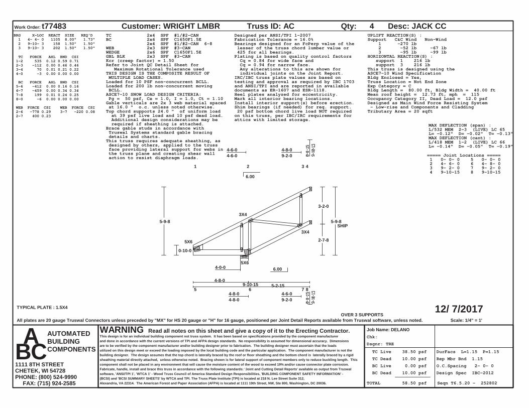
Work Order: t77483 Customer: WRIGHT LMBR
Job Name: DELANO
Truss ID: AC Qty: 4 Desc: JACK CC
WARNING Read all notes on this sheet and give a copy of it to the Erecting Contractor.This design is for an individual building component not truss system. It has been based on specifications provided by the component manufacturerand done in accordance with the current versions of TPI and AFPA design standards. No responsibility is assumed for dimensional accuracy. Dimensionsare to be verified by the component manufacturer and/or building designer prior to fabrication. The building designer must ascertain that the loadsutilized on this design meet or exceed the loading imposed by the local building code and the particular application. The component manufacturer is not thebuilding designer. The design assumes that the top chord is laterally braced by the roof or floor sheathing and the bottom chord is laterally braced by a rigidsheathing material directly attached, unless otherwise noted. Bracing shown is for lateral support of component members only to reduce buckling length. Thiscomponent shall not be placed in any environment that will cause the moisture content of the wood to exceed 19% and/or cause connector plate corrosion.Fabricate, handle, install and brace this truss in accordance with the following standards: 'Joint and Cutting Detail Reports' available as output from Truswalsoftware, 'ANSI/TPI 1', 'WTCA 1' - Wood Truss Council of America Standard Design Responsibilities, 'BUILDING COMPONENT SAFETY INFORMATION' -(BCSI) and 'BCSI SUMMARY SHEETS' by WTCA and TPI. The Truss Plate Institute (TPI) is located at 218 N. Lee Street Suite 312,Alexandria, VA 22314. The American Forest and Paper Association (AFPA) is located at 1111 19th Street, NW, Ste 800, Washington, DC 20036.
AUTOMATEDBUILDINGCOMPONENTS
A B C 1111 8TH STREETCHETEK, WI 54728PHONE: (800) 524-9990 FAX: (715) 924-2585
6.00
6.00
OVER 3 SUPPORTSScale: 1/4" = 1'
1 2 3 4
4-6-04-6-0
4-8-09-2-0
5 6 7 8 4-8-04-8-0
4-6-09-2-0
TYPICAL PLATE : 1.5X4
5X6
3X4
5X6
3X4
4-0-0
9-10-15
0-10-0
5-9-8
3-2-0
2-7-8
5-9-8
4-8-05-2-15
SHIP
BRG X-LOC REACT SIZE REQ'D 1 4- 4- 0 1105 8.00" 1.73" 2 9-10- 3 158 1.50" 1.50" 3 9-10- 3 202 1.50" 1.50"
TC FORCE AXL BND CSI 1-2 535 0.12 0.59 0.71 2-3 -112 0.00 0.46 0.46 3-4 70 0.01 0.21 0.22 4-0 -3 0.00 0.00 0.00
BC FORCE AXL BND CSI 5-6 -412 0.00 0.16 0.16 6-7 -459 0.00 0.34 0.34 7-8 199 0.01 0.24 0.25 8-0 -6 0.00 0.00 0.00
WEB FORCE CSI WEB FORCE CSI 2-6 -778 0.29 2-7 400 0.23 3-7 -220 0.08
TC 2x4 SPF #1/#2-CANBC 2x6 SPF C1650F1.5E 2x4 SPF #1/#2-CAN 6-8WEB 2x3 SPF #3-CANWEDGE 2x6 SPF C1650F1.5EGBL BLK 2x3 SPF #3-CAN
Designed per ANSI/TPI 1-2007Fabrication Tolerance = 16.0%Bearings designed for an FcPerp value of the lesser of the truss chord lumber value or 425 for all bearings.Plating is based on quality control factors Cq = 0.84 for wide face and Cq = 0.94 for narrow face. Any alterations to this are shown for individual joints on the Joint Report.
Kcr (creep factor) = 1.50Refer to Joint QC Detail Sheet for Maximum Rotational Tolerance usedTHIS DESIGN IS THE COMPOSITE RESULT OF MULTIPLE LOAD CASES. IRC/IBC truss plate values are based on
testing and approval as required by IBC 1703and ANSI/TPI and are reported in availabledocuments as ER-1607 and ESR-1118.
Loaded for 10 PSF non-concurrent BCLL.Loaded for 200 lb non-concurrent moving BCLL.
Heel plates analyzed for eccentricity.ASCE7-10 SNOW LOAD DESIGN CRITERIA: Pg = 50 psf, Ce = 1.0, I = 1.0, Ct = 1.10 Mark all interior bearing locations.
Install interior support(s) before erection.Gable verticals are 2x 3 web material spaced at 16.0 " o.c. unless noted otherwise.Top chord supports 24.0 " of uniform load at 39 psf live load and 10 psf dead load. Additional design considerations may be required if sheathing is attached.Brace gable studs in accordance with Truswal Systems standard gable bracing details and charts.This truss requires adequate sheathing, as designed by others, applied to the truss face providing lateral support for webs in the truss plane and creating shear wall action to resist diaphragm loads.
Shim bearings (if needed) for req. support.
UPLIFT REACTION(S) :Support C&C Wind Non-Wind 1 -270 lb 2 -52 lb -67 lb 3 -95 lb -99 lbHORIZONTAL REACTION(S) : support 1 216 lb support 3 216 lbThis truss is designed using theASCE7-10 Wind SpecificationBldg Enclosed = Yes,Truss Location = Not End ZoneExp Category = CBldg Length = 80.00 ft, Bldg Width = 40.00 ftMean roof height = 12.73 ft, mph = 115Occupancy Category II, Dead Load = 12.0 psfDesigned as Main Wind Force Resisting System - Low-rise and Components and CladdingTributary Area = 20 sqft 20 psf bottom chord live load NOT required
on this truss, per IBC/IRC requirements forattics with limited storage.
MAX DEFLECTION (span) :L/532 MEM 2-3 (LIVE) LC 65L= -0.12" D= -0.02" T= -0.13"MAX DEFLECTION (cant) :L/418 MEM 1-2 (LIVE) LC 66L= -0.14" D= -0.05" T= -0.19"
===== Joint Locations ===== 1 0- 0- 0 5 0- 0- 0 2 4- 6- 0 6 4- 8- 0 3 9- 2- 0 7 9- 2- 0 4 9-10-15 8 9-10-15
All plates are 20 gauge Truswal Connectors unless preceded by "MX" for HS 20 gauge or "H" for 16 gauge, positioned per Joint Detail Reports available from Truswal software, unless noted.

Dsgnr: TRE
Chk:
TC Live 38.50 psf
TC Dead 10.00 psf
BC Live 0.00 psf
BC Dead 10.00 psf
TOTAL 58.50 psf
DurFacs L=1.15 P=1.15
Rep Mbr Bnd 1.15
O.C.Spacing 2- 0- 0
Design Spec IBC-2012
Seqn T6.5.20 - 252803
12/ 7/2017
Work Order: t77483 Customer: WRIGHT LMBR
Job Name: DELANO
Truss ID: AD Qty: 4 Desc: JACK CC
WARNING Read all notes on this sheet and give a copy of it to the Erecting Contractor.This design is for an individual building component not truss system. It has been based on specifications provided by the component manufacturerand done in accordance with the current versions of TPI and AFPA design standards. No responsibility is assumed for dimensional accuracy. Dimensionsare to be verified by the component manufacturer and/or building designer prior to fabrication. The building designer must ascertain that the loadsutilized on this design meet or exceed the loading imposed by the local building code and the particular application. The component manufacturer is not thebuilding designer. The design assumes that the top chord is laterally braced by the roof or floor sheathing and the bottom chord is laterally braced by a rigidsheathing material directly attached, unless otherwise noted. Bracing shown is for lateral support of component members only to reduce buckling length. Thiscomponent shall not be placed in any environment that will cause the moisture content of the wood to exceed 19% and/or cause connector plate corrosion.Fabricate, handle, install and brace this truss in accordance with the following standards: 'Joint and Cutting Detail Reports' available as output from Truswalsoftware, 'ANSI/TPI 1', 'WTCA 1' - Wood Truss Council of America Standard Design Responsibilities, 'BUILDING COMPONENT SAFETY INFORMATION' -(BCSI) and 'BCSI SUMMARY SHEETS' by WTCA and TPI. The Truss Plate Institute (TPI) is located at 218 N. Lee Street Suite 312,Alexandria, VA 22314. The American Forest and Paper Association (AFPA) is located at 1111 19th Street, NW, Ste 800, Washington, DC 20036.
AUTOMATEDBUILDINGCOMPONENTS
A B C 1111 8TH STREETCHETEK, WI 54728PHONE: (800) 524-9990 FAX: (715) 924-2585
6.00
6.00
OVER 3 SUPPORTSScale: 5/16" = 1'
1 2 3 4
4-8-04-8-0
2-0-06-8-0
5 6 7 8 4-8-04-8-0
2-0-06-8-0
TYPICAL PLATE : 1.5X4
5X6
3X4
5X6
3X4
4-0-0
7-10-15
0-10-0
4-9-8
3-2-0
1-7-8
4-9-8
4-8-03-2-15
SHIP
BRG X-LOC REACT SIZE REQ'D 1 4- 4- 0 1150 8.00" 1.80" 2 7-10- 3 153 1.50" 1.50" 3 7-10- 3 105 1.50" 1.50"
TC FORCE AXL BND CSI 1-2 543 0.12 0.47 0.59 2-3 -77 0.00 0.48 0.49 3-4 -93 0.00 0.37 0.37 4-0 -3 0.00 0.00 0.00
BC FORCE AXL BND CSI 5-6 -419 0.00 0.16 0.17 6-7 -407 0.00 0.44 0.44 7-8 193 0.00 0.42 0.42 8-0 -6 0.00 0.00 0.00
WEB FORCE CSI WEB FORCE CSI 2-6 -944 0.35 2-7 588 0.33 3-7 -301 0.11
TC 2x4 SPF #1/#2-CANBC 2x6 SPF C1650F1.5E 2x4 SPF #1/#2-CAN 6-8WEB 2x3 SPF #3-CANWEDGE 2x6 SPF C1650F1.5EGBL BLK 2x3 SPF #3-CAN
Designed per ANSI/TPI 1-2007Fabrication Tolerance = 16.0%Bearings designed for an FcPerp value of the lesser of the truss chord lumber value or 425 for all bearings.Plating is based on quality control factors Cq = 0.84 for wide face and Cq = 0.94 for narrow face. Any alterations to this are shown for individual joints on the Joint Report.
Kcr (creep factor) = 1.50Refer to Joint QC Detail Sheet for Maximum Rotational Tolerance usedTHIS DESIGN IS THE COMPOSITE RESULT OF MULTIPLE LOAD CASES. IRC/IBC truss plate values are based on
testing and approval as required by IBC 1703and ANSI/TPI and are reported in availabledocuments as ER-1607 and ESR-1118.
Loaded for 10 PSF non-concurrent BCLL.Loaded for 200 lb non-concurrent moving BCLL.
Heel plates analyzed for eccentricity.ASCE7-10 SNOW LOAD DESIGN CRITERIA: Pg = 50 psf, Ce = 1.0, I = 1.0, Ct = 1.10 Mark all interior bearing locations.
Install interior support(s) before erection.Gable verticals are 2x 3 web material spaced at 16.0 " o.c. unless noted otherwise.Top chord supports 24.0 " of uniform load at 39 psf live load and 10 psf dead load. Additional design considerations may be required if sheathing is attached.Brace gable studs in accordance with Truswal Systems standard gable bracing details and charts.This truss requires adequate sheathing, as designed by others, applied to the truss face providing lateral support for webs in the truss plane and creating shear wall action to resist diaphragm loads.
Shim bearings (if needed) for req. support.
UPLIFT REACTION(S) :Support C&C Wind Non-Wind 1 -295 lb 2 -86 lb -175 lb 3 -67 lb -179 lbHORIZONTAL REACTION(S) : support 1 184 lb support 3 184 lbThis truss is designed using theASCE7-10 Wind SpecificationBldg Enclosed = Yes,Truss Location = Not End ZoneExp Category = CBldg Length = 80.00 ft, Bldg Width = 40.00 ftMean roof height = 12.23 ft, mph = 115Occupancy Category II, Dead Load = 12.0 psfDesigned as Main Wind Force Resisting System - Low-rise and Components and CladdingTributary Area = 16 sqft 20 psf bottom chord live load NOT required
on this truss, per IBC/IRC requirements forattics with limited storage.
MAX DEFLECTION (span) :L/901 MEM 2-3 (LIVE) LC 64L= 0.04" D= 0.02" T= 0.06"MAX DEFLECTION (cant) :L/323 MEM 1-2 (LIVE) LC 64L= -0.18" D= -0.11" T= -0.28"
===== Joint Locations ===== 1 0- 0- 0 5 0- 0- 0 2 4- 8- 0 6 4- 8- 0 3 6- 8- 0 7 6- 8- 0 4 7-10-15 8 7-10-15
All plates are 20 gauge Truswal Connectors unless preceded by "MX" for HS 20 gauge or "H" for 16 gauge, positioned per Joint Detail Reports available from Truswal software, unless noted.

Dsgnr: TRE
Chk:
TC Live 38.50 psf
TC Dead 10.00 psf
BC Live 0.00 psf
BC Dead 10.00 psf
TOTAL 58.50 psf
DurFacs L=1.15 P=1.15
Rep Mbr Bnd 1.15
O.C.Spacing 2- 0- 0
Design Spec IBC-2012
Seqn T6.5.20 - 252804
12/ 7/2017
Work Order: t77483 Customer: WRIGHT LMBR
Job Name: DELANO
Truss ID: AE Qty: 4 Desc: JACK CC
WARNING Read all notes on this sheet and give a copy of it to the Erecting Contractor.This design is for an individual building component not truss system. It has been based on specifications provided by the component manufacturerand done in accordance with the current versions of TPI and AFPA design standards. No responsibility is assumed for dimensional accuracy. Dimensionsare to be verified by the component manufacturer and/or building designer prior to fabrication. The building designer must ascertain that the loadsutilized on this design meet or exceed the loading imposed by the local building code and the particular application. The component manufacturer is not thebuilding designer. The design assumes that the top chord is laterally braced by the roof or floor sheathing and the bottom chord is laterally braced by a rigidsheathing material directly attached, unless otherwise noted. Bracing shown is for lateral support of component members only to reduce buckling length. Thiscomponent shall not be placed in any environment that will cause the moisture content of the wood to exceed 19% and/or cause connector plate corrosion.Fabricate, handle, install and brace this truss in accordance with the following standards: 'Joint and Cutting Detail Reports' available as output from Truswalsoftware, 'ANSI/TPI 1', 'WTCA 1' - Wood Truss Council of America Standard Design Responsibilities, 'BUILDING COMPONENT SAFETY INFORMATION' -(BCSI) and 'BCSI SUMMARY SHEETS' by WTCA and TPI. The Truss Plate Institute (TPI) is located at 218 N. Lee Street Suite 312,Alexandria, VA 22314. The American Forest and Paper Association (AFPA) is located at 1111 19th Street, NW, Ste 800, Washington, DC 20036.
AUTOMATEDBUILDINGCOMPONENTS
A B C 1111 8TH STREETCHETEK, WI 54728PHONE: (800) 524-9990 FAX: (715) 924-2585
6.00
6.00
OVER 3 SUPPORTSScale: 13/32" = 1'
1 2 3 4 5
2-4-02-4-0
2-4-04-8-0
6 7 8 9 102-4-02-4-0
2-4-04-8-0TYPICAL PLATE : 1.5X4
5X6
3X4
5X6
8X8
3X6
4-0-0
5-10-15
0-10-0
3-9-83-2-0
0-7-8
3-9-8
4-8-01-2-15
SHIP
BRG X-LOC REACT SIZE REQ'D 1 4- 4- 0 1765 8.00" 2.77" 2 5-10- 3 152 1.50" 1.50" 3 5-10- 3 148 1.50" 1.50"
TC FORCE AXL BND CSI 1-2 275 0.02 0.09 0.11 2-3 517 0.07 0.24 0.31 3-4 549 0.07 0.45 0.52 4-5 -290 0.00 0.34 0.35 5-0 -288 0.00 0.30 0.30 0-0 -3 0.00 0.00 0.00
BC FORCE AXL BND CSI 6-7 -224 0.00 0.06 0.06 7-8 -230 0.00 0.06 0.06 8-9 164 0.02 0.41 0.43 9-10 -224 0.00 0.32 0.3210-0 -6 0.00 0.00 0.00
WEB FORCE CSI WEB FORCE CSI 2-7 222 0.13 2-8 -295 0.11 3-8 146 0.08
4-8 -1794 0.72 4-9 701 0.43
TC 2x4 DFL 1800F-1.6EBC 2x6 SPF C1650F1.5E 2x4 SPF #1/#2-CAN 8-10WEB 2x3 SPF #3-CANWEDGE 2x6 SPF C1650F1.5EGBL BLK 2x3 SPF #3-CANLumber shear allowables are per NDS.
**[PM]=PLATE MONITOR USED-See Joint Report**Designed per ANSI/TPI 1-2007Fabrication Tolerance = 16.0%Bearings designed for an FcPerp value of the lesser of the truss chord lumber value or 425 for all bearings.Plating is based on quality control factors Cq = 0.84 for wide face and Cq = 0.94 for narrow face. Any alterations to this are shown for individual joints on the Joint Report.
Kcr (creep factor) = 1.50Refer to Joint QC Detail Sheet for Maximum Rotational Tolerance usedTHIS DESIGN IS THE COMPOSITE RESULT OF MULTIPLE LOAD CASES. IRC/IBC truss plate values are based on
testing and approval as required by IBC 1703and ANSI/TPI and are reported in availabledocuments as ER-1607 and ESR-1118.
Loaded for 10 PSF non-concurrent BCLL.Loaded for 200 lb non-concurrent moving BCLL.
Heel plates analyzed for eccentricity.ASCE7-10 SNOW LOAD DESIGN CRITERIA: Pg = 50 psf, Ce = 1.0, I = 1.0, Ct = 1.10 Mark all interior bearing locations.
Install interior support(s) before erection.Gable verticals are 2x 3 web material spaced at 16.0 " o.c. unless noted otherwise.Top chord supports 24.0 " of uniform load at 39 psf live load and 10 psf dead load. Additional design considerations may be required if sheathing is attached.Brace gable studs in accordance with Truswal Systems standard gable bracing details and charts.This truss requires adequate sheathing, as designed by others, applied to the truss face providing lateral support for webs in the truss plane and creating shear wall action to resist diaphragm loads.
Shim bearings (if needed) for req. support.
UPLIFT REACTION(S) :Support C&C Wind Non-Wind 1 -498 lb -163 lb 2 -249 lb -629 lb 3 -213 lb -492 lbDue to high uplift reaction, this truss requires special connection details (designed by others) to secure truss to a rigidly anchored support.HORIZONTAL REACTION(S) : support 1 142 lb support 3 142 lbThis truss is designed using theASCE7-10 Wind SpecificationBldg Enclosed = Yes,Truss Location = Not End ZoneExp Category = CBldg Length = 80.00 ft, Bldg Width = 40.00 ftMean roof height = 11.73 ft, mph = 115Occupancy Category II, Dead Load = 12.0 psfDesigned as Main Wind Force Resisting System - Low-rise and Components and CladdingTributary Area = 12 sqft
20 psf bottom chord live load NOT requiredon this truss, per IBC/IRC requirements forattics with limited storage.
MAX DEFLECTION (span) :L/999 MEM 3-4 (LIVE) LC 53L= 0.01" D= 0.01" T= 0.01"MAX DEFLECTION (cant) :L/374 MEM 6-7 (LIVE) LC 53L= -0.15" D= -0.11" T= -0.26"
===== Joint Locations ===== 1 0- 0- 0 6 0- 0- 0 2 2- 4- 0 7 2- 4- 0 3 4- 8- 0 8 4- 8- 0 4 5- 7- 0 9 5- 7- 0 5 5-10-15 10 5-10-15
All plates are 20 gauge Truswal Connectors unless preceded by "MX" for HS 20 gauge or "H" for 16 gauge, positioned per Joint Detail Reports available from Truswal software, unless noted.
Dsgnr: TRE
Chk:
TC Live 38.50 psf
TC Dead 10.00 psf
BC Live 0.00 psf
BC Dead 10.00 psf
TOTAL 58.50 psf
DurFacs L=1.15 P=1.15
Rep Mbr Bnd 1.00
O.C.Spacing 2- 0- 0
Design Spec IBC-2012
Seqn T6.5.20 - 252805
12/ 7/2017
Work Order: t77483 Customer: WRIGHT LMBR
Job Name: DELANO
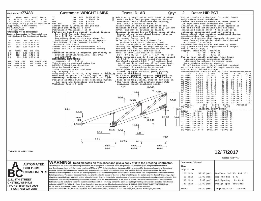
Truss ID: AR Qty: 2 Desc: HIP PCT
WARNING Read all notes on this sheet and give a copy of it to the Erecting Contractor.This design is for an individual building component not truss system. It has been based on specifications provided by the component manufacturerand done in accordance with the current versions of TPI and AFPA design standards. No responsibility is assumed for dimensional accuracy. Dimensionsare to be verified by the component manufacturer and/or building designer prior to fabrication. The building designer must ascertain that the loadsutilized on this design meet or exceed the loading imposed by the local building code and the particular application. The component manufacturer is not thebuilding designer. The design assumes that the top chord is laterally braced by the roof or floor sheathing and the bottom chord is laterally braced by a rigidsheathing material directly attached, unless otherwise noted. Bracing shown is for lateral support of component members only to reduce buckling length. Thiscomponent shall not be placed in any environment that will cause the moisture content of the wood to exceed 19% and/or cause connector plate corrosion.Fabricate, handle, install and brace this truss in accordance with the following standards: 'Joint and Cutting Detail Reports' available as output from Truswalsoftware, 'ANSI/TPI 1', 'WTCA 1' - Wood Truss Council of America Standard Design Responsibilities, 'BUILDING COMPONENT SAFETY INFORMATION' -(BCSI) and 'BCSI SUMMARY SHEETS' by WTCA and TPI. The Truss Plate Institute (TPI) is located at 218 N. Lee Street Suite 312,Alexandria, VA 22314. The American Forest and Paper Association (AFPA) is located at 1111 19th Street, NW, Ste 800, Washington, DC 20036.
AUTOMATEDBUILDINGCOMPONENTS
A B C 1111 8TH STREETCHETEK, WI 54728PHONE: (800) 524-9990 FAX: (715) 924-2585
4.24
4.27
Scale: 7/32" = 1'
1 2 3 4
6-6-06-6-0
5-1-911-7-9
5-1-916-9-1
5 6 7 8 6-6-76-6-7
5-1-211-7-9
5-1-916-9-1
TYPICAL PLATE : 1.5X4
3X8
10X10
4X14
10X10
4X14
7X16
5-7-2
16-9-1
0-10-0
6-9-1
3-2-11
3-6-6
6-9-1
6-6-79-11-2
0-3-8
3-7-12468# 0-1-12
8-5-1
11-3-0
14-0-15
8-5-1
11-3-0
14-0-15
SHIP
BRG X-LOC REACT SIZE REQ'D 1 6- 0-13 3016 11.31" 4.73" 2 16- 8- 5 1265 HGR 1.98"A 20 gauge (min.) plate is required at support(s), 2 for bearing.BRG HANGER/CLIP NOTE 2 Hanger TBE**HANGER(S) TO BE ENGINEEREDSupport Connection(s)/Hanger(s) are not designed for horizontal loads.
TC FORCE AXL BND CSI 1-2 2190 0.10 0.51 0.61 2-3 2270 0.12 0.83 0.96 3-4 2824 0.15 0.19 0.34
BC FORCE AXL BND CSI 5-6 -1948 0.02 0.34 0.36 6-7 -3119 0.04 0.76 0.80 7-8 156 0.00 0.35 0.35
WEB FORCE CSI WEB FORCE CSI 2-6 -996 0.29 3-6 -2786 0.98 3-7 573 0.25
4-7 -3531 1.00 8-4 1372 0.61
TC 2x6 DFL 2400F-2.0EBC 2x6 SPF C1650F1.5EWEB 2x4 SPF #3-CANGBL BLK 2x3 SPF #3-CANLumber shear allowables are per NDS.
Web bracing required at each location shown. Refer to BCSI for proper required lateral restraint. For alternative web bracing, see ITWBCG's standard details.Plates outside the truss perimeter aredesigned for the location shown only (DO NOTMOVE!) and may be trimmed or folded.
Designed per ANSI/TPI 1-2007Fabrication Tolerance = 16.0%
Bearings designed for an FcPerp value of the lesser of the truss chord lumber value or 425 for all bearings.
Plating is based on quality control factors Cq = 0.84 for wide face and Cq = 0.94 for narrow face. Any alterations to this are shown for individual joints on the Joint Report.
Kcr (creep factor) = 1.50Refer to Joint QC Detail Sheet for Maximum Rotational Tolerance usedTHIS DESIGN IS THE COMPOSITE RESULT OF
MULTIPLE LOAD CASES. IRC/IBC truss plate values are based ontesting and approval as required by IBC 1703and ANSI/TPI and are reported in availabledocuments as ER-1607 and ESR-1118.
Loaded for 10 PSF non-concurrent BCLL.Loaded for 200 lb non-concurrent moving BCLL.
ASCE7-10 SNOW LOAD DESIGN CRITERIA: Pg = 50 psf, Ce = 1.0, I = 1.0, Ct = 1.10
Permanent bracing is required (by others) to prevent rotation/toppling. See BCSI and ANSI/TPI 1. Gable verticals are 2x 3 web material spaced
at 16.0 " o.c. unless noted otherwise.Top chord supports 24.0 " of uniform load at 39 psf live load and 10 psf dead load. Additional design considerations may be required if sheathing is attached.Brace gable studs in accordance with Truswal Systems standard gable bracing details and charts.This truss requires adequate sheathing, as designed by others, applied to the truss face providing lateral support for webs in the truss plane and creating shear wall action to resist diaphragm loads.
End verticals are designed for axial loadsonly unless noted otherwise.Extensions above or below the truss profile(if any) have been designed for loadsindicated only. Horizontal loads applied atthe end of the extensions have not beenconsidered unless shown. A drop-leg to anotherwise unsupported wall may create ahinge effect that requires additional designconsideration (by others).Hanger nail points that protrude through the back face of the girder shall be clinched or covered for safety.Required bearing widths and bearing areasapply when truss not supported in a hanger.UPLIFT REACTION(S) :Support Main Wind Non-Wind 1 -407 lb -1527 lb 2 -424 lb -1352 lbDue to high uplift reaction, this truss requires special connection details (designed by others) to secure truss to a rigidly anchored support.
HORIZONTAL REACTION(S) : support 2 114 lbThis truss is designed using theASCE7-10 Wind SpecificationBldg Enclosed = Yes,Truss Location = Not End ZoneExp Category = CBldg Length = 80.00 ft, Bldg Width = 40.00 ftMean roof height = 13.14 ft, mph = 115Occupancy Category II, Dead Load = 12.0 psfDesigned as Main Wind Force Resisting System - Low-rise and Components and CladdingTributary Area = 0 sqft
20 psf bottom chord live load NOT requiredon this truss, per IBC/IRC requirements forattics with limited storage.----------LOAD CASE #1 DESIGN LOADS ---------------- Dir L.Plf L.Loc R.Plf R.Loc LL/TLTC Vert 97.00 0- 0- 0 97.00 7- 5- 1 0.79TC Vert 48.50 7- 5- 1 48.50 9- 5- 1 0.79TC Vert 97.00 9- 5- 1 97.00 10- 3- 0 0.79TC Vert 48.50 10- 3- 0 48.50 12- 3- 0 0.79TC Vert 97.00 12- 3- 0 97.00 13- 0-15 0.79TC Vert 48.50 13- 0-15 48.50 15- 0-15 0.79TC Vert 97.00 15- 0-15 97.00 16- 9- 1 0.79BC Vert 20.00 0- 0- 0 20.00 7- 5- 1 0.00BC Vert 10.00 7- 5- 1 10.00 9- 5- 1 0.00BC Vert 20.00 9- 5- 1 20.00 10- 3- 0 0.00BC Vert 10.00 10- 3- 0 10.00 12- 3- 0 0.00BC Vert 20.00 12- 3- 0 20.00 13- 0-15 0.00BC Vert 10.00 13- 0-15 10.00 15- 0-15 0.00BC Vert 20.00 15- 0-15 20.00 16- 9- 1 0.00...Type... lbs X.Loc LL/TL FastenerTC Vert 468.0 0- 1-12 0.70------------ CRITICAL POINT LOADS ------------------ Type X.Loc Max/Dur Min/DurTC Vert 8- 5- 1 145/1.60 -629/1.15TC Vert 8- 5- 1 145/1.60 -629/1.15TC Vert 11- 3- 0 152/1.60 -168/1.15TC Vert 11- 3- 0 152/1.60 -168/1.15TC Vert 14- 0-15 146/1.60 -47/1.15TC Vert 14- 0-15 146/1.60 -47/1.15BC Vert 8- 5- 1 115/1.60 -487/1.15BC Vert 8- 5- 1 115/1.60 -487/1.15BC Vert 11- 3- 0 105/1.60 -179/1.15

BC Vert 11- 3- 0 105/1.60 -179/1.15BC Vert 14- 0-15 202/1.60 -99/1.15BC Vert 14- 0-15 202/1.60 -99/1.15
MAX DEFLECTION (span) :L/957 MEM 6-7 (LIVE) LC 35L= 0.13" D= 0.08" T= 0.21"MAX DEFLECTION (cant) :L/277 MEM 1-2 (LIVE) LC 35L= -0.28" D= -0.19" T= -0.47"
===== Joint Locations ===== 1 0- 0- 0 5 0- 0- 0 2 6- 6- 0 6 6- 6- 7 3 11- 7- 9 7 11- 7- 9 4 16- 9- 1 8 16- 9- 1
All plates are 20 gauge Truswal Connectors unless preceded by "MX" for HS 20 gauge or "H" for 16 gauge, positioned per Joint Detail Reports available from Truswal software, unless noted.

Dsgnr: TRE
Chk:
TC Live 38.50 psf
TC Dead 10.00 psf
BC Live 0.00 psf
BC Dead 10.00 psf
TOTAL 58.50 psf
DurFacs L=1.15 P=1.15
Rep Mbr Bnd 1.00
O.C.Spacing 2- 0- 0
Design Spec IBC-2012
Seqn T6.5.20 - 252806
12/ 7/2017
Work Order: t77483 Customer: WRIGHT LMBR
Job Name: DELANO
Truss ID: B Qty: 2 Desc: GIRDER
WARNING Read all notes on this sheet and give a copy of it to the Erecting Contractor.This design is for an individual building component not truss system. It has been based on specifications provided by the component manufacturerand done in accordance with the current versions of TPI and AFPA design standards. No responsibility is assumed for dimensional accuracy. Dimensionsare to be verified by the component manufacturer and/or building designer prior to fabrication. The building designer must ascertain that the loadsutilized on this design meet or exceed the loading imposed by the local building code and the particular application. The component manufacturer is not thebuilding designer. The design assumes that the top chord is laterally braced by the roof or floor sheathing and the bottom chord is laterally braced by a rigidsheathing material directly attached, unless otherwise noted. Bracing shown is for lateral support of component members only to reduce buckling length. Thiscomponent shall not be placed in any environment that will cause the moisture content of the wood to exceed 19% and/or cause connector plate corrosion.Fabricate, handle, install and brace this truss in accordance with the following standards: 'Joint and Cutting Detail Reports' available as output from Truswalsoftware, 'ANSI/TPI 1', 'WTCA 1' - Wood Truss Council of America Standard Design Responsibilities, 'BUILDING COMPONENT SAFETY INFORMATION' -(BCSI) and 'BCSI SUMMARY SHEETS' by WTCA and TPI. The Truss Plate Institute (TPI) is located at 218 N. Lee Street Suite 312,Alexandria, VA 22314. The American Forest and Paper Association (AFPA) is located at 1111 19th Street, NW, Ste 800, Washington, DC 20036.
AUTOMATEDBUILDINGCOMPONENTS
A B C 1111 8TH STREETCHETEK, WI 54728PHONE: (800) 524-9990 FAX: (715) 924-2585
6.00 -6.00
Scale: 7/32" = 1'
1 2 3 4 5
5-9-05-9-0
4-3-010-0-0
4-3-014-3-0
5-9-020-0-0
6 7 8 9 105-9-05-9-0
4-3-010-0-0
4-3-014-3-0
5-9-020-0-0
SS0712
SS0712 1.5X4 SS0712
SS0712
2X410X10 10X10 10X10
2X4
2-PLYSREQUIRED
20-0-0
2-10-0
5-8-8
2-10-0
5-8-8
5-9-0 8-6-0 5-9-0
(2) 10d2-0-0
(2) 10d4-0-0
(2) 10d6-1-14 8-0-0 10-0-0 12-0-0
(2) 10d13-10-2
(2) 10d16-0-0
(2) 10d18-0-0
5-6-13
SHIP
BRG X-LOC REACT SIZE REQ'D 1 0- 4- 0 10464 8.00" 5.76" 2 19- 8- 0 10464 8.00" 5.76"
TC FORCE AXL BND CSI 1-2 -10382 0.48 0.50 0.98 2-3 -11359 0.56 0.37 0.93 3-4 -11359 0.56 0.37 0.93 4-5 -10382 0.48 0.50 0.98
BC FORCE AXL BND CSI 6-7 -28 0.00 0.29 0.29 7-8 9248 0.19 0.23 0.42 8-9 9248 0.19 0.23 0.42 9-10 0 0.00 0.29 0.29
WEB FORCE CSI WEB FORCE CSI 1-6 -9201 0.33 1-7 10167 0.83 2-7 1689 0.37 2-8 3156 0.70 3-8 -352 0.08
4-8 3157 0.70 4-9 1689 0.37 5-9 10167 0.83 5-10 -9201 0.33
TC 2x4 SPF C1650F1.5E 2x4 SPF #1/#2-CAN 2-4BC 2x8 SP 2400F-2.0EWEB 2x4 SPF #3-CAN 2x6 SPF C1650F1.5E 6-1, 10-5 2x4 SPF C1650F1.5E 1-7, 9-5Lumber shear allowables are per NDS.
**[PM]=PLATE MONITOR USED-See Joint Report**Designed per ANSI/TPI 1-2007Fabrication Tolerance = 16.0%Bearings designed for an FcPerp value of the lesser of the truss chord lumber value or 605 for all bearings.Plating is based on quality control factors Cq = 0.84 for wide face and Cq = 0.94 for narrow face. Any alterations to this are shown for individual joints on the Joint Report.
Kcr (creep factor) = 1.50Refer to Joint QC Detail Sheet for Maximum Rotational Tolerance usedTHIS DESIGN IS THE COMPOSITE RESULT OF MULTIPLE LOAD CASES. IRC/IBC truss plate values are based on
testing and approval as required by IBC 1703and ANSI/TPI and are reported in availabledocuments as ER-1607 and ESR-1118.
Loaded for 10 PSF non-concurrent BCLL.Loaded for 200 lb non-concurrent moving BCLL.
ASCE7-10 SNOW LOAD DESIGN CRITERIA: Pg = 50 psf, Ce = 1.0, I = 1.0, Ct = 1.10 Pm = 20 psfLu Parallel to Ridge = 20-0-0Minimum Lu = 20-00-00
+ + + + + + + + + + + + + + + + + + + + + +Nail pattern shown is for PLF loads andpoint loads converted to PLF loads only.Concentrated loads MUST be distributed toeach ply equally. Multi-ply with hangers arebased on hanger nails using 3.0" nails min.into the carrying member.If shown, use additional fasteners for pointloads as indicated from the back plys,distributed symmetrically around the hanger.Use any other approved detail (by others).10d = 10d NAILS, SDS = Simpson SDS screws or equivalent substitute.(*) = Special Connection Req. (by others)@ = Indicates load is evenly distributed (no additional fasteners req.)+ + + + + + + + + + + + + + + + + + + + + ++ + + + + + + + + + + + + + + + + + + + + +NAIL pattern shown is based on: 10d BOX = 0.128" dia. x 3.0" long nail 10d COMMON = 0.148" dia. x 3.0" long nail 16d BOX = 0.135" dia. x 3.5" long nail 16d COMMON = 0.162" dia. x 3.5" long nail+ + + + + + + + + + + + + + + + + + + + + +
Drainage must be provided to avoid ponding.Permanent bracing is required (by others) to prevent rotation/toppling. See BCSI and ANSI/TPI 1.End verticals are designed for axial loadsonly unless noted otherwise.Extensions above or below the truss profile(if any) have been designed for loadsindicated only. Horizontal loads applied atthe end of the extensions have not beenconsidered unless shown. A drop-leg to anotherwise unsupported wall may create ahinge effect that requires additional designconsideration (by others).
2-PLY! Nail w/10d COMMON, staggered(per NDS) in: TC- 4 BC- 2 WEBS- 2 **PER FOOT!** Cluster screws, if shown, are 3" long.Web 6-1 requires 3/FT nailing.Web 10-5 requires 3/FT nailing. This design based on chord bracing applied
per the following schedule: max o.c. from to TC 24.00" 5- 9- 0 14- 3- 0
Hip-Drop : 0-1-11This truss is designed using theASCE7-10 Wind SpecificationBldg Enclosed = Yes,Truss Location = Not End ZoneExp Category = CBldg Length = 80.00 ft, Bldg Width = 40.00 ftMean roof height = 12.85 ft, mph = 115Occupancy Category II, Dead Load = 12.0 psfDesigned as Main Wind Force Resisting System - Low-rise and Components and CladdingTributary Area = 285 sqft
20 psf bottom chord live load NOT requiredon this truss, per IBC/IRC requirements forattics with limited storage.----------LOAD CASE #1 DESIGN LOADS ---------------- Dir L.Plf L.Loc R.Plf R.Loc LL/TLTC Vert 97.00 0- 0- 0 97.00 20- 0- 0 0.79BC Vert 20.00 0- 0- 0 20.00 1- 0- 0 0.00BC Vert 10.00 1- 0- 0 10.00 19- 0- 0 0.00BC Vert 20.00 19- 0- 0 20.00 20- 0- 0 0.00------------ CRITICAL POINT LOADS ------------------ Type X.Loc Max/Dur Min/DurBC Vert 2- 0- 0 1424/1.15 -80/1.60BC Vert 4- 0- 0 1735/1.15 235/1.60BC Vert 5-10- 8 593/1.15 -1092/1.15BC Vert 6- 0- 0 1735/1.15 235/1.60BC Vert 6- 0- 0 245/1.60 -462/1.15BC Vert 8- 0- 0 355/1.60 -95/1.15BC Vert 8- 0- 0 2051/1.15 551/1.60BC Vert 10- 0- 0 355/1.60 -95/1.15BC Vert 10- 0- 0 2051/1.15 551/1.60BC Vert 12- 0- 0 2051/1.15 551/1.60BC Vert 12- 0- 0 355/1.60 -95/1.15BC Vert 14- 0- 0 245/1.60 -462/1.15BC Vert 14- 0- 0 1735/1.15 235/1.60BC Vert 14- 1- 8 593/1.15 -1092/1.15BC Vert 16- 0- 0 1735/1.15 235/1.60BC Vert 18- 0- 0 1424/1.15 -80/1.60
MAX DEFLECTION (span) :L/999 MEM 2-3 (LIVE) LC 43L= -0.15" D= -0.13" T= -0.28"
===== Joint Locations ===== 1 0- 0- 0 6 0- 0- 0 2 5- 9- 0 7 5- 9- 0 3 10- 0- 0 8 10- 0- 0 4 14- 3- 0 9 14- 3- 0 5 20- 0- 0 10 20- 0- 0
All plates are 20 gauge Truswal Connectors unless preceded by "MX" for HS 20 gauge or "H" for 16 gauge, positioned per Joint Detail Reports available from Truswal software, unless noted.

Dsgnr: TRE
Chk:
TC Live 38.50 psf
TC Dead 10.00 psf
BC Live 0.00 psf
BC Dead 10.00 psf
TOTAL 58.50 psf
DurFacs L=1.15 P=1.15
Rep Mbr Bnd 1.15
O.C.Spacing 2- 0- 0
Design Spec IBC-2012
Seqn T6.5.20 - 252807
12/ 7/2017
Work Order: t77483 Customer: WRIGHT LMBR
Job Name: DELANO
Truss ID: BA Qty: 3 Desc: MONO
WARNING Read all notes on this sheet and give a copy of it to the Erecting Contractor.This design is for an individual building component not truss system. It has been based on specifications provided by the component manufacturerand done in accordance with the current versions of TPI and AFPA design standards. No responsibility is assumed for dimensional accuracy. Dimensionsare to be verified by the component manufacturer and/or building designer prior to fabrication. The building designer must ascertain that the loadsutilized on this design meet or exceed the loading imposed by the local building code and the particular application. The component manufacturer is not thebuilding designer. The design assumes that the top chord is laterally braced by the roof or floor sheathing and the bottom chord is laterally braced by a rigidsheathing material directly attached, unless otherwise noted. Bracing shown is for lateral support of component members only to reduce buckling length. Thiscomponent shall not be placed in any environment that will cause the moisture content of the wood to exceed 19% and/or cause connector plate corrosion.Fabricate, handle, install and brace this truss in accordance with the following standards: 'Joint and Cutting Detail Reports' available as output from Truswalsoftware, 'ANSI/TPI 1', 'WTCA 1' - Wood Truss Council of America Standard Design Responsibilities, 'BUILDING COMPONENT SAFETY INFORMATION' -(BCSI) and 'BCSI SUMMARY SHEETS' by WTCA and TPI. The Truss Plate Institute (TPI) is located at 218 N. Lee Street Suite 312,Alexandria, VA 22314. The American Forest and Paper Association (AFPA) is located at 1111 19th Street, NW, Ste 800, Washington, DC 20036.
AUTOMATEDBUILDINGCOMPONENTS
A B C 1111 8TH STREETCHETEK, WI 54728PHONE: (800) 524-9990 FAX: (715) 924-2585
6.00
Scale: 9/32" = 1'
1 2 3
4-1-44-1-4
5-7-129-9-0
4 5 6 4-1-44-1-4
5-7-129-9-0
5X6
3X4
1.5X4
2X43X4
4-0-0
9-9-0
0-10-0
5-8-8 5-8-8
BRG X-LOC REACT SIZE REQ'D 1 4- 4- 0 1025 8.00" 1.61" 2 9- 8- 4 356 HGR 1.50"BRG HANGER/CLIP NOTE 2 Hanger TBE**HANGER(S) TO BE ENGINEEREDSupport Connection(s)/Hanger(s) are not designed for horizontal loads.
TC FORCE AXL BND CSI 1-2 416 0.08 0.70 0.79 2-3 -145 0.00 0.58 0.59
BC FORCE AXL BND CSI 4-5 -327 0.00 0.12 0.12 5-6 -358 0.00 0.14 0.14
WEB FORCE CSI WEB FORCE CSI 2-5 -844 0.29 2-6 394 0.22 3-6 -235 0.13
TC 2x4 SPF #1/#2-CANBC 2x6 SPF C1650F1.5EWEB 2x3 SPF #3-CAN 2x4 SPF #3-CAN 6-3WEDGE 2x6 SPF C1650F1.5ELumber shear allowables are per NDS.
Designed per ANSI/TPI 1-2007Fabrication Tolerance = 16.0%Bearings designed for an FcPerp value of the lesser of the truss chord lumber value or 425 for all bearings.Plating is based on quality control factors Cq = 0.84 for wide face and Cq = 0.94 for narrow face. Any alterations to this are shown for individual joints on the Joint Report.
Kcr (creep factor) = 1.50Refer to Joint QC Detail Sheet for Maximum Rotational Tolerance usedTHIS DESIGN IS THE COMPOSITE RESULT OF MULTIPLE LOAD CASES. IRC/IBC truss plate values are based on
testing and approval as required by IBC 1703and ANSI/TPI and are reported in availabledocuments as ER-1607 and ESR-1118.
Loaded for 10 PSF non-concurrent BCLL.Loaded for 200 lb non-concurrent moving BCLL.
Heel plates analyzed for eccentricity.ASCE7-10 SNOW LOAD DESIGN CRITERIA: Pg = 50 psf, Ce = 1.0, I = 1.0, Ct = 1.10
End verticals are designed for axial loadsonly unless noted otherwise.Extensions above or below the truss profile(if any) have been designed for loadsindicated only. Horizontal loads applied atthe end of the extensions have not beenconsidered unless shown. A drop-leg to anotherwise unsupported wall may create ahinge effect that requires additional designconsideration (by others).
Hanger nail points that protrude through the back face of the girder shall be clinched or covered for safety.
Required bearing widths and bearing areasapply when truss not supported in a hanger.UPLIFT REACTION(S) :Support C&C Wind Non-Wind 1 -199 lb 2 -147 lb -103 lb
HORIZONTAL REACTION(S) : support 1 214 lb support 2 214 lb
This truss is designed using theASCE7-10 Wind SpecificationBldg Enclosed = Yes,Truss Location = Not End ZoneExp Category = CBldg Length = 80.00 ft, Bldg Width = 40.00 ftMean roof height = 12.69 ft, mph = 115Occupancy Category II, Dead Load = 12.0 psfDesigned as Main Wind Force Resisting System - Low-rise and Components and CladdingTributary Area = 20 sqft
20 psf bottom chord live load NOT requiredon this truss, per IBC/IRC requirements forattics with limited storage.
MAX DEFLECTION (span) :L/401 MEM 2-3 (LIVE) LC 65L= -0.16" D= -0.05" T= -0.21"MAX DEFLECTION (cant) :L/689 MEM 1-2 (LIVE) LC 66L= -0.08" D= -0.03" T= -0.11"
===== Joint Locations ===== 1 0- 0- 0 4 0- 0- 0 2 4- 1- 4 5 4- 1- 4 3 9- 9- 0 6 9- 9- 0
All plates are 20 gauge Truswal Connectors unless preceded by "MX" for HS 20 gauge or "H" for 16 gauge, positioned per Joint Detail Reports available from Truswal software, unless noted.
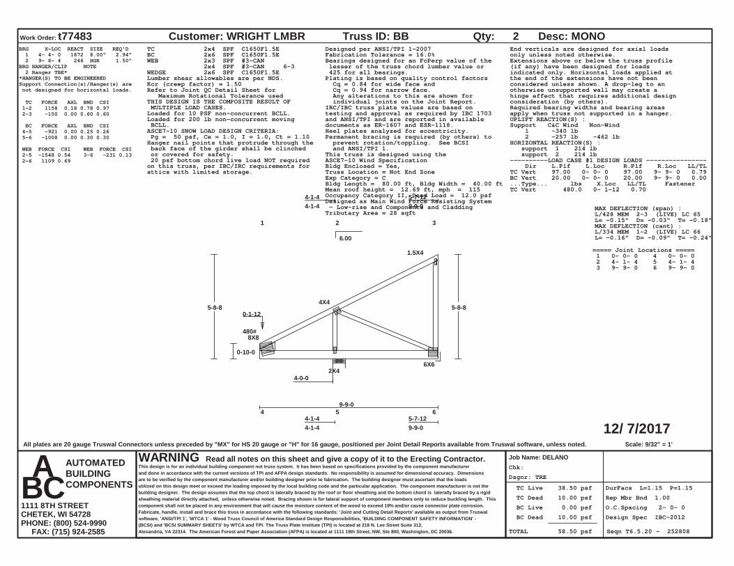
Dsgnr: TRE
Chk:
TC Live 38.50 psf
TC Dead 10.00 psf
BC Live 0.00 psf
BC Dead 10.00 psf
TOTAL 58.50 psf
DurFacs L=1.15 P=1.15
Rep Mbr Bnd 1.00
O.C.Spacing 2- 0- 0
Design Spec IBC-2012
Seqn T6.5.20 - 252808
12/ 7/2017
Work Order: t77483 Customer: WRIGHT LMBR
Job Name: DELANO
Truss ID: BB Qty: 2 Desc: MONO
WARNING Read all notes on this sheet and give a copy of it to the Erecting Contractor.This design is for an individual building component not truss system. It has been based on specifications provided by the component manufacturerand done in accordance with the current versions of TPI and AFPA design standards. No responsibility is assumed for dimensional accuracy. Dimensionsare to be verified by the component manufacturer and/or building designer prior to fabrication. The building designer must ascertain that the loadsutilized on this design meet or exceed the loading imposed by the local building code and the particular application. The component manufacturer is not thebuilding designer. The design assumes that the top chord is laterally braced by the roof or floor sheathing and the bottom chord is laterally braced by a rigidsheathing material directly attached, unless otherwise noted. Bracing shown is for lateral support of component members only to reduce buckling length. Thiscomponent shall not be placed in any environment that will cause the moisture content of the wood to exceed 19% and/or cause connector plate corrosion.Fabricate, handle, install and brace this truss in accordance with the following standards: 'Joint and Cutting Detail Reports' available as output from Truswalsoftware, 'ANSI/TPI 1', 'WTCA 1' - Wood Truss Council of America Standard Design Responsibilities, 'BUILDING COMPONENT SAFETY INFORMATION' -(BCSI) and 'BCSI SUMMARY SHEETS' by WTCA and TPI. The Truss Plate Institute (TPI) is located at 218 N. Lee Street Suite 312,Alexandria, VA 22314. The American Forest and Paper Association (AFPA) is located at 1111 19th Street, NW, Ste 800, Washington, DC 20036.
AUTOMATEDBUILDINGCOMPONENTS
A B C 1111 8TH STREETCHETEK, WI 54728PHONE: (800) 524-9990 FAX: (715) 924-2585
6.00
Scale: 9/32" = 1'
1 2 3
4-1-44-1-4
5-7-129-9-0
4 5 6 4-1-44-1-4
5-7-129-9-0
8X8
4X4
1.5X4
2X46X6
4-0-0
9-9-0
0-10-0
5-8-8 5-8-8
480# 0-1-12
BRG X-LOC REACT SIZE REQ'D 1 4- 4- 0 1872 8.00" 2.94" 2 9- 8- 4 246 HGR 1.50"BRG HANGER/CLIP NOTE 2 Hanger TBE**HANGER(S) TO BE ENGINEEREDSupport Connection(s)/Hanger(s) are not designed for horizontal loads.
TC FORCE AXL BND CSI 1-2 1158 0.18 0.78 0.97 2-3 -150 0.00 0.60 0.60
BC FORCE AXL BND CSI 4-5 -921 0.00 0.25 0.26 5-6 -1008 0.00 0.30 0.30
WEB FORCE CSI WEB FORCE CSI 2-5 -1548 0.54 2-6 1109 0.69 3-6 -231 0.13
TC 2x4 SPF C1650F1.5EBC 2x6 SPF C1650F1.5EWEB 2x3 SPF #3-CAN 2x4 SPF #3-CAN 6-3WEDGE 2x6 SPF C1650F1.5ELumber shear allowables are per NDS.
Designed per ANSI/TPI 1-2007Fabrication Tolerance = 16.0%Bearings designed for an FcPerp value of the lesser of the truss chord lumber value or 425 for all bearings.Plating is based on quality control factors Cq = 0.84 for wide face and Cq = 0.94 for narrow face. Any alterations to this are shown for individual joints on the Joint Report.
Kcr (creep factor) = 1.50Refer to Joint QC Detail Sheet for Maximum Rotational Tolerance usedTHIS DESIGN IS THE COMPOSITE RESULT OF MULTIPLE LOAD CASES. IRC/IBC truss plate values are based on
testing and approval as required by IBC 1703and ANSI/TPI and are reported in availabledocuments as ER-1607 and ESR-1118.
Loaded for 10 PSF non-concurrent BCLL.Loaded for 200 lb non-concurrent moving BCLL.
Heel plates analyzed for eccentricity.ASCE7-10 SNOW LOAD DESIGN CRITERIA: Pg = 50 psf, Ce = 1.0, I = 1.0, Ct = 1.10 Permanent bracing is required (by others) to
prevent rotation/toppling. See BCSI and ANSI/TPI 1.
End verticals are designed for axial loadsonly unless noted otherwise.Extensions above or below the truss profile(if any) have been designed for loadsindicated only. Horizontal loads applied atthe end of the extensions have not beenconsidered unless shown. A drop-leg to anotherwise unsupported wall may create ahinge effect that requires additional designconsideration (by others).
Hanger nail points that protrude through the back face of the girder shall be clinched or covered for safety.
Required bearing widths and bearing areasapply when truss not supported in a hanger.UPLIFT REACTION(S) :Support C&C Wind Non-Wind 1 -340 lb 2 -257 lb -462 lbHORIZONTAL REACTION(S) : support 1 214 lb support 2 214 lbThis truss is designed using the
ASCE7-10 Wind SpecificationBldg Enclosed = Yes,Truss Location = Not End ZoneExp Category = CBldg Length = 80.00 ft, Bldg Width = 40.00 ftMean roof height = 12.69 ft, mph = 115Occupancy Category II, Dead Load = 12.0 psfDesigned as Main Wind Force Resisting System - Low-rise and Components and CladdingTributary Area = 28 sqft
20 psf bottom chord live load NOT requiredon this truss, per IBC/IRC requirements forattics with limited storage.
----------LOAD CASE #1 DESIGN LOADS ---------------- Dir L.Plf L.Loc R.Plf R.Loc LL/TLTC Vert 97.00 0- 0- 0 97.00 9- 9- 0 0.79BC Vert 20.00 0- 0- 0 20.00 9- 9- 0 0.00...Type... lbs X.Loc LL/TL FastenerTC Vert 480.0 0- 1-12 0.70
MAX DEFLECTION (span) :L/428 MEM 2-3 (LIVE) LC 65L= -0.15" D= -0.03" T= -0.18"MAX DEFLECTION (cant) :L/334 MEM 1-2 (LIVE) LC 66L= -0.16" D= -0.09" T= -0.24"
===== Joint Locations ===== 1 0- 0- 0 4 0- 0- 0 2 4- 1- 4 5 4- 1- 4 3 9- 9- 0 6 9- 9- 0
All plates are 20 gauge Truswal Connectors unless preceded by "MX" for HS 20 gauge or "H" for 16 gauge, positioned per Joint Detail Reports available from Truswal software, unless noted.
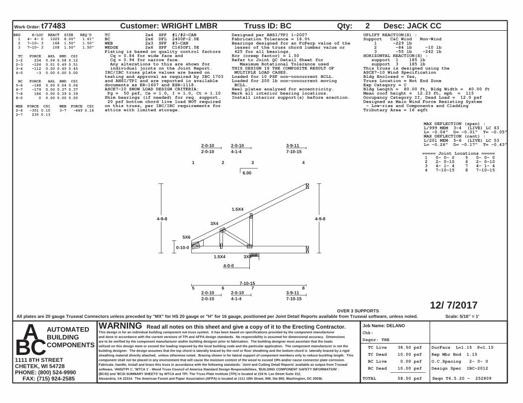
Dsgnr: TRE
Chk:
TC Live 38.50 psf
TC Dead 10.00 psf
BC Live 0.00 psf
BC Dead 10.00 psf
TOTAL 58.50 psf
DurFacs L=1.15 P=1.15
Rep Mbr Bnd 1.15
O.C.Spacing 2- 0- 0
Design Spec IBC-2012
Seqn T6.5.20 - 252809
12/ 7/2017
Work Order: t77483 Customer: WRIGHT LMBR
Job Name: DELANO
Truss ID: BC Qty: 2 Desc: JACK CC
WARNING Read all notes on this sheet and give a copy of it to the Erecting Contractor.This design is for an individual building component not truss system. It has been based on specifications provided by the component manufacturerand done in accordance with the current versions of TPI and AFPA design standards. No responsibility is assumed for dimensional accuracy. Dimensionsare to be verified by the component manufacturer and/or building designer prior to fabrication. The building designer must ascertain that the loadsutilized on this design meet or exceed the loading imposed by the local building code and the particular application. The component manufacturer is not thebuilding designer. The design assumes that the top chord is laterally braced by the roof or floor sheathing and the bottom chord is laterally braced by a rigidsheathing material directly attached, unless otherwise noted. Bracing shown is for lateral support of component members only to reduce buckling length. Thiscomponent shall not be placed in any environment that will cause the moisture content of the wood to exceed 19% and/or cause connector plate corrosion.Fabricate, handle, install and brace this truss in accordance with the following standards: 'Joint and Cutting Detail Reports' available as output from Truswalsoftware, 'ANSI/TPI 1', 'WTCA 1' - Wood Truss Council of America Standard Design Responsibilities, 'BUILDING COMPONENT SAFETY INFORMATION' -(BCSI) and 'BCSI SUMMARY SHEETS' by WTCA and TPI. The Truss Plate Institute (TPI) is located at 218 N. Lee Street Suite 312,Alexandria, VA 22314. The American Forest and Paper Association (AFPA) is located at 1111 19th Street, NW, Ste 800, Washington, DC 20036.
AUTOMATEDBUILDINGCOMPONENTS
A B C 1111 8TH STREETCHETEK, WI 54728PHONE: (800) 524-9990 FAX: (715) 924-2585
6.00
OVER 3 SUPPORTSScale: 5/16" = 1'
1 2 3 4
2-0-102-0-10
2-0-104-1-4
3-9-117-10-15
5 6 7 8 2-0-102-0-10
2-0-104-1-4
3-9-117-10-15
5X6
3X4
1.5X4
1.5X4 3X4
4-0-0
7-10-15
0-10-0
4-9-8 4-9-8
BRG X-LOC REACT SIZE REQ'D 1 4- 4- 0 1025 8.00" 1.61" 2 7-10- 3 168 1.50" 1.50" 3 7-10- 3 108 1.50" 1.50"
TC FORCE AXL BND CSI 1-2 234 0.04 0.08 0.12 2-3 -124 0.01 0.49 0.51 3-4 -112 0.00 0.45 0.45 4-0 -3 0.00 0.00 0.00
BC FORCE AXL BND CSI 5-6 -188 0.00 0.04 0.04 6-7 -179 0.00 0.37 0.37 7-8 186 0.00 0.39 0.39 8-0 0 0.00 0.00 0.00
WEB FORCE CSI WEB FORCE CSI 2-6 -301 0.10 2-7 235 0.13 3-7 -449 0.16
TC 2x4 SPF #1/#2-CANBC 2x6 DFL 2400F-2.0EWEB 2x3 SPF #3-CANWEDGE 2x6 SPF C1650F1.5E
Designed per ANSI/TPI 1-2007Fabrication Tolerance = 16.0%Bearings designed for an FcPerp value of the lesser of the truss chord lumber value or 425 for all bearings.Plating is based on quality control factors
Cq = 0.84 for wide face and Cq = 0.94 for narrow face. Any alterations to this are shown for individual joints on the Joint Report.
Kcr (creep factor) = 1.50Refer to Joint QC Detail Sheet for Maximum Rotational Tolerance usedTHIS DESIGN IS THE COMPOSITE RESULT OF MULTIPLE LOAD CASES.IRC/IBC truss plate values are based on
testing and approval as required by IBC 1703and ANSI/TPI and are reported in availabledocuments as ER-1607 and ESR-1118.
Loaded for 10 PSF non-concurrent BCLL.Loaded for 200 lb non-concurrent moving BCLL.Heel plates analyzed for eccentricity.ASCE7-10 SNOW LOAD DESIGN CRITERIA:
Pg = 50 psf, Ce = 1.0, I = 1.0, Ct = 1.10 Mark all interior bearing locations.Install interior support(s) before erection.Shim bearings (if needed) for req. support.
UPLIFT REACTION(S) :Support C&C Wind Non-Wind 1 -229 lb 2 -84 lb -10 lb 3 -55 lb -242 lbHORIZONTAL REACTION(S) : support 1 185 lb support 3 185 lbThis truss is designed using theASCE7-10 Wind SpecificationBldg Enclosed = Yes,Truss Location = Not End ZoneExp Category = CBldg Length = 80.00 ft, Bldg Width = 40.00 ftMean roof height = 12.23 ft, mph = 115Occupancy Category II, Dead Load = 12.0 psfDesigned as Main Wind Force Resisting System - Low-rise and Components and CladdingTributary Area = 16 sqft
20 psf bottom chord live load NOT requiredon this truss, per IBC/IRC requirements forattics with limited storage.
MAX DEFLECTION (span) :L/999 MEM 3-4 (LIVE) LC 63L= -0.04" D= -0.01" T= -0.05"MAX DEFLECTION (cant) :L/201 MEM 5-6 (LIVE) LC 53L= -0.26" D= -0.17" T= -0.43"
===== Joint Locations ===== 1 0- 0- 0 5 0- 0- 0 2 2- 0-10 6 2- 0-10 3 4- 1- 4 7 4- 1- 4 4 7-10-15 8 7-10-15
All plates are 20 gauge Truswal Connectors unless preceded by "MX" for HS 20 gauge or "H" for 16 gauge, positioned per Joint Detail Reports available from Truswal software, unless noted.

Dsgnr: TRE
Chk:
TC Live 38.50 psf
TC Dead 10.00 psf
BC Live 0.00 psf
BC Dead 10.00 psf
TOTAL 58.50 psf
DurFacs L=1.15 P=1.15
Rep Mbr Bnd 1.15
O.C.Spacing 2- 0- 0
Design Spec IBC-2012
Seqn T6.5.20 - 252810
12/ 7/2017
Work Order: t77483 Customer: WRIGHT LMBR
Job Name: DELANO
Truss ID: BD Qty: 4 Desc: JACK CC
WARNING Read all notes on this sheet and give a copy of it to the Erecting Contractor.This design is for an individual building component not truss system. It has been based on specifications provided by the component manufacturerand done in accordance with the current versions of TPI and AFPA design standards. No responsibility is assumed for dimensional accuracy. Dimensionsare to be verified by the component manufacturer and/or building designer prior to fabrication. The building designer must ascertain that the loadsutilized on this design meet or exceed the loading imposed by the local building code and the particular application. The component manufacturer is not thebuilding designer. The design assumes that the top chord is laterally braced by the roof or floor sheathing and the bottom chord is laterally braced by a rigidsheathing material directly attached, unless otherwise noted. Bracing shown is for lateral support of component members only to reduce buckling length. Thiscomponent shall not be placed in any environment that will cause the moisture content of the wood to exceed 19% and/or cause connector plate corrosion.Fabricate, handle, install and brace this truss in accordance with the following standards: 'Joint and Cutting Detail Reports' available as output from Truswalsoftware, 'ANSI/TPI 1', 'WTCA 1' - Wood Truss Council of America Standard Design Responsibilities, 'BUILDING COMPONENT SAFETY INFORMATION' -(BCSI) and 'BCSI SUMMARY SHEETS' by WTCA and TPI. The Truss Plate Institute (TPI) is located at 218 N. Lee Street Suite 312,Alexandria, VA 22314. The American Forest and Paper Association (AFPA) is located at 1111 19th Street, NW, Ste 800, Washington, DC 20036.
AUTOMATEDBUILDINGCOMPONENTS
A B C 1111 8TH STREETCHETEK, WI 54728PHONE: (800) 524-9990 FAX: (715) 924-2585
6.00
OVER 3 SUPPORTSScale: 13/32" = 1'
1 2 3
4-1-44-1-4
1-9-115-10-15
4 5 6 4-1-44-1-4
1-9-115-10-15
5X6
1.5X4
2X44-0-0
5-10-15
0-10-0
3-9-8 3-9-8
BRG X-LOC REACT SIZE REQ'D 1 4- 4- 0 1320 8.00" 2.07" 2 5-10- 3 84 1.50" 1.50" 3 5-10- 3 182 1.50" 1.50"
TC FORCE AXL BND CSI 1-2 -113 0.01 0.42 0.44 2-3 -100 0.00 0.45 0.45 3-0 -3 0.00 0.00 0.00
BC FORCE AXL BND CSI 4-5 130 0.00 0.44 0.45 5-6 144 0.00 0.35 0.35 6-0 0 0.00 0.00 0.00
WEB FORCE CSI WEB FORCE CSI 2-5 -443 0.15
TC 2x4 SPF #1/#2-CANBC 2x6 DFL 2400F-2.0EWEB 2x3 SPF #3-CANWEDGE 2x6 SPF C1650F1.5ELumber shear allowables are per NDS.
Designed per ANSI/TPI 1-2007Fabrication Tolerance = 16.0%Bearings designed for an FcPerp value of the lesser of the truss chord lumber value or 425 for all bearings.Plating is based on quality control factors Cq = 0.84 for wide face and Cq = 0.94 for narrow face. Any alterations to this are shown for individual joints on the Joint Report.
Kcr (creep factor) = 1.50Refer to Joint QC Detail Sheet for Maximum Rotational Tolerance usedTHIS DESIGN IS THE COMPOSITE RESULT OF MULTIPLE LOAD CASES.
IRC/IBC truss plate values are based ontesting and approval as required by IBC 1703and ANSI/TPI and are reported in availabledocuments as ER-1607 and ESR-1118.
Loaded for 10 PSF non-concurrent BCLL.Loaded for 200 lb non-concurrent moving BCLL.Heel plates analyzed for eccentricity.
ASCE7-10 SNOW LOAD DESIGN CRITERIA: Pg = 50 psf, Ce = 1.0, I = 1.0, Ct = 1.10
Mark all interior bearing locations.Install interior support(s) before erection.
Shim bearings (if needed) for req. support.
UPLIFT REACTION(S) :Support C&C Wind Non-Wind 1 -356 lb -121 lb 2 -31 lb -114 lb 3 -224 lb -642 lb
Due to high uplift reaction, this truss requires special connection details (designed by others) to secure truss to a rigidly anchored support.
HORIZONTAL REACTION(S) : support 1 144 lb support 3 144 lbThis truss is designed using theASCE7-10 Wind SpecificationBldg Enclosed = Yes,Truss Location = Not End ZoneExp Category = CBldg Length = 80.00 ft, Bldg Width = 40.00 ftMean roof height = 11.73 ft, mph = 115Occupancy Category II, Dead Load = 12.0 psfDesigned as Main Wind Force Resisting System - Low-rise and Components and CladdingTributary Area = 12 sqft
20 psf bottom chord live load NOT requiredon this truss, per IBC/IRC requirements forattics with limited storage.
MAX DEFLECTION (span) :L/999 MEM 2-3 (LIVE) LC 53L= -0.02" D= -0.01" T= -0.03"MAX DEFLECTION (cant) :L/212 MEM 4-5 (LIVE) LC 53L= -0.25" D= -0.16" T= -0.41"
===== Joint Locations ===== 1 0- 0- 0 4 0- 0- 0 2 4- 1- 4 5 4- 1- 4 3 5-10-15 6 5-10-15
All plates are 20 gauge Truswal Connectors unless preceded by "MX" for HS 20 gauge or "H" for 16 gauge, positioned per Joint Detail Reports available from Truswal software, unless noted.

Dsgnr: TRE
Chk:
TC Live 38.50 psf
TC Dead 10.00 psf
BC Live 0.00 psf
BC Dead 10.00 psf
TOTAL 58.50 psf
DurFacs L=1.15 P=1.15
Rep Mbr Bnd 1.15
O.C.Spacing 2- 0- 0
Design Spec IBC-2012
Seqn T6.5.20 - 252811
12/ 7/2017
Work Order: t77483 Customer: WRIGHT LMBR
Job Name: DELANO
Truss ID: BE Qty: 2 Desc: JACK CC
WARNING Read all notes on this sheet and give a copy of it to the Erecting Contractor.This design is for an individual building component not truss system. It has been based on specifications provided by the component manufacturerand done in accordance with the current versions of TPI and AFPA design standards. No responsibility is assumed for dimensional accuracy. Dimensionsare to be verified by the component manufacturer and/or building designer prior to fabrication. The building designer must ascertain that the loadsutilized on this design meet or exceed the loading imposed by the local building code and the particular application. The component manufacturer is not thebuilding designer. The design assumes that the top chord is laterally braced by the roof or floor sheathing and the bottom chord is laterally braced by a rigidsheathing material directly attached, unless otherwise noted. Bracing shown is for lateral support of component members only to reduce buckling length. Thiscomponent shall not be placed in any environment that will cause the moisture content of the wood to exceed 19% and/or cause connector plate corrosion.Fabricate, handle, install and brace this truss in accordance with the following standards: 'Joint and Cutting Detail Reports' available as output from Truswalsoftware, 'ANSI/TPI 1', 'WTCA 1' - Wood Truss Council of America Standard Design Responsibilities, 'BUILDING COMPONENT SAFETY INFORMATION' -(BCSI) and 'BCSI SUMMARY SHEETS' by WTCA and TPI. The Truss Plate Institute (TPI) is located at 218 N. Lee Street Suite 312,Alexandria, VA 22314. The American Forest and Paper Association (AFPA) is located at 1111 19th Street, NW, Ste 800, Washington, DC 20036.
AUTOMATEDBUILDINGCOMPONENTS
A B C 1111 8TH STREETCHETEK, WI 54728PHONE: (800) 524-9990 FAX: (715) 924-2585
6.00
OVER 3 SUPPORTSScale: 5/16" = 1'
1 2
3-10-153-10-15
3 4 3-10-153-10-15
1.5X4
2X4
3-10-15
2-10-0
4-9-8 4-9-8
BRG X-LOC REACT SIZE REQ'D 1 0- 4- 0 261 8.00" 1.50" 2 3-10- 3 185 1.50" 1.50" 3 3-10- 3 201 1.50" 1.50"
TC FORCE AXL BND CSI 1-2 -80 0.00 0.35 0.35 2-0 -3 0.00 0.00 0.00
BC FORCE AXL BND CSI 3-4 0 0.00 0.34 0.34 4-0 0 0.00 0.00 0.00
WEB FORCE CSI WEB FORCE CSI 1-3 -194 0.05
TC 2x4 SPF #1/#2-CANBC 2x4 SPF #1/#2-CANWEB 2x4 SPF #3-CAN
Designed per ANSI/TPI 1-2007Fabrication Tolerance = 16.0%Bearings designed for an FcPerp value of the lesser of the truss chord lumber value or 425 for all bearings.
Plating is based on quality control factors Cq = 0.84 for wide face and Cq = 0.94 for narrow face. Any alterations to this are shown for individual joints on the Joint Report.
Kcr (creep factor) = 1.50Refer to Joint QC Detail Sheet for Maximum Rotational Tolerance usedTHIS DESIGN IS THE COMPOSITE RESULT OF MULTIPLE LOAD CASES.
IRC/IBC truss plate values are based ontesting and approval as required by IBC 1703and ANSI/TPI and are reported in availabledocuments as ER-1607 and ESR-1118.
Loaded for 10 PSF non-concurrent BCLL.Loaded for 200 lb non-concurrent moving BCLL.ASCE7-10 SNOW LOAD DESIGN CRITERIA:
Pg = 50 psf, Ce = 1.0, I = 1.0, Ct = 1.10 Mark all interior bearing locations.Install interior support(s) before erection.Shim bearings (if needed) for req. support.
End verticals are designed for axial loadsonly unless noted otherwise.Extensions above or below the truss profile(if any) have been designed for loadsindicated only. Horizontal loads applied atthe end of the extensions have not beenconsidered unless shown. A drop-leg to anotherwise unsupported wall may create ahinge effect that requires additional designconsideration (by others).UPLIFT REACTION(S) :Support C&C Wind Non-Wind 1 -82 lb 2 -50 lbThis truss is designed using theASCE7-10 Wind SpecificationBldg Enclosed = Yes,Truss Location = Not End ZoneExp Category = CBldg Length = 80.00 ft, Bldg Width = 40.00 ftMean roof height = 12.23 ft, mph = 115Occupancy Category II, Dead Load = 12.0 psfDesigned as Main Wind Force Resisting System - Low-rise and Components and CladdingTributary Area = 8 sqft
20 psf bottom chord live load NOT requiredon this truss, per IBC/IRC requirements forattics with limited storage.
MAX DEFLECTION (span) :L/912 MEM 1-2 (LIVE) LC 1L= -0.05" D= -0.02" T= -0.07"
===== Joint Locations ===== 1 0- 0- 0 3 0- 0- 0 2 3-10-15 4 3-10-15
All plates are 20 gauge Truswal Connectors unless preceded by "MX" for HS 20 gauge or "H" for 16 gauge, positioned per Joint Detail Reports available from Truswal software, unless noted.

Dsgnr: TRE
Chk:
TC Live 38.50 psf
TC Dead 10.00 psf
BC Live 0.00 psf
BC Dead 10.00 psf
TOTAL 58.50 psf
DurFacs L=1.15 P=1.15
Rep Mbr Bnd 1.00
O.C.Spacing 2- 0- 0
Design Spec IBC-2012
Seqn T6.5.20 - 252812
12/ 7/2017
Work O
rder:t77483C
ustomer: W
RIG
HT LM
BR
Job Nam
e: DELAN
O
Truss ID: B
RQ
ty: 2D
esc: HIP M
ON
O
WAR
NIN
GR
ead all notes on this sheet and give a copy of it to the Erecting Contractor.
This design is for an individual building component not truss system
. It has been based on specifications provided by the component m
anufacturerand done in accordance w
ith the current versions of TPI and AFPA design standards. No responsibility is assum
ed for dimensional accuracy. D
imensions
are to be verified by the component m
anufacturer and/or building designer prior to fabrication. The building designer must ascertain that the loads
utilized on this design meet or exceed the loading im
posed by the local building code and the particular application. The component m
anufacturer is not thebuilding designer. The design assum
es that the top chord is laterally braced by the roof or floor sheathing and the bottom chord is laterally braced by a rigid
sheathing material directly attached, unless otherw
ise noted. Bracing show
n is for lateral support of component m
embers only to reduce buckling length. This
component shall not be placed in any environm
ent that will cause the m
oisture content of the wood to exceed 19%
and/or cause connector plate corrosion.Fabricate, handle, install and brace this truss in accordance w
ith the following standards: 'Joint and C
utting Detail R
eports' available as output from Trusw
alsoftw
are, 'ANSI/TPI 1', 'W
TCA 1' - W
ood Truss Council of Am
erica Standard Design R
esponsibilities, 'BU
ILDIN
G C
OM
PON
ENT SAFETY IN
FOR
MATIO
N' -
(BC
SI) and 'BC
SI SUM
MAR
Y SHEETS' by W
TCA and TPI. The Truss Plate Institute (TPI) is located at 218 N
. Lee Street Suite 312,Alexandria, VA 22314. The Am
erican Forest and Paper Association (AFPA) is located at 1111 19th Street, NW
, Ste 800, Washington, D
C 20036.
AU
TOM
ATED
BU
ILDIN
GC
OM
PON
ENTS
A
B C
1111 8TH STR
EETC
HETEK
, WI 54728
PHO
NE: (800) 524-9990
FAX: (715) 924-2585
4.24
Scale: 9/32" = 1'
1 2
3
5-9-85-9-8
7-10-713-7-15
4 5
6 5-9-85-9-8
7-10-713-7-15
3X8
4X8
1.5X4
2X48X8
5-7-2
13-7-15
0-10-0
5-7-155-7-15
480# 0-1-12
8-5-1
11-3-0
8-5-1
11-3-0
BRG X-LOC REACT SIZE REQ'D 1 6- 0-13 2629 11.31" 4.12" 2 13- 7- 3 740 HGR 1.50"BRG HANGER/CLIP NOTE 2 Hanger TBE**HANGER(S) TO BE ENGINEEREDSupport Connection(s)/Hanger(s) are not designed for horizontal loads.
TC FORCE AXL BND CSI 1-2 2245 0.16 0.82 0.98 2-3 -209 0.00 0.72 0.72
BC FORCE AXL BND CSI 4-5 -1985 0.00 0.42 0.43 5-6 -2095 0.02 0.89 0.90
WEB FORCE CSI WEB FORCE CSI 2-5 -2179 0.53 2-6 2199 0.54 3-6 -500 0.26
TC 2x6 SPF C1650F1.5E
BC 2x6 DFL 2400F-2.0E
WEB 2x4 SPF #3-CAN
2x4 SPF #1/#2-CAN 2-6
Lumber shear allowables are per NDS.
Designed per ANSI/TPI 1-2007
Fabrication Tolerance = 16.0%
Bearings designed for an FcPerp value of the
lesser of the truss chord lumber value or
425 for all bearings.
Plating is based on quality control factors
Cq = 0.84 for wide face and
Cq = 0.94 for narrow face.
Any alterations to this are shown for
individual joints on the Joint Report.
Kcr (creep factor) = 1.50
Refer to Joint QC Detail Sheet for
Maximum Rotational Tolerance used
THIS DESIGN IS THE COMPOSITE RESULT OF
MULTIPLE LOAD CASES.
IRC/IBC truss plate values are based on
testing and approval as required by IBC 1703
and ANSI/TPI and are reported in available
documents as ER-1607 and ESR-1118.
Loaded for 10 PSF non-concurrent BCLL.
Loaded for 200 lb non-concurrent moving
BCLL.
ASCE7-10 SNOW LOAD DESIGN CRITERIA:
Pg = 50 psf, Ce = 1.0, I = 1.0, Ct = 1.10
Permanent bracing is required (by others) to
prevent rotation/toppling. See BCSI
and ANSI/TPI 1.
End verticals are designed for axial loads
only unless noted otherwise.
Extensions above or below the truss profile
(if any) have been designed for loads
indicated only. Horizontal loads applied at
the end of the extensions have not been
considered unless shown. A drop-leg to an
otherwise unsupported wall may create a
hinge effect that requires additional design
consideration (by others).
Hanger nail points that protrude through the
back face of the girder shall be clinched
or covered for safety.
Required bearing widths and bearing areas
apply when truss not supported in a hanger.
UPLIFT REACTION(S) :
Support Main Wind Non-Wind
1 -412 lb
2 -335 lb -1092 lb
Due to high uplift reaction, this truss
requires special connection details
(designed by others) to secure truss
to a rigidly anchored support.
This truss is designed using the
ASCE7-10 Wind Specification
Bldg Enclosed = Yes,
Truss Location = Not End Zone
Exp Category = C
Bldg Length = 80.00 ft, Bldg Width = 40.00 ft
Mean roof height = 12.59 ft, mph = 115
Occupancy Category II, Dead Load = 12.0 psf
Designed as Main Wind Force Resisting System
- Low-rise and Components and Cladding
Tributary Area = 12 sqft
20 psf bottom chord live load NOT required
on this truss, per IBC/IRC requirements for
attics with limited storage.
----------LOAD CASE #1 DESIGN LOADS ----------------
Dir L.Plf L.Loc R.Plf R.Loc LL/TL
TC Vert 97.00 0- 0- 0 97.00 7- 5- 1 0.79
TC Vert 48.50 7- 5- 1 48.50 9- 5- 1 0.79
TC Vert 97.00 9- 5- 1 97.00 10- 3- 0 0.79
TC Vert 48.50 10- 3- 0 48.50 12- 3- 0 0.79
TC Vert 97.00 12- 3- 0 97.00 13- 7-15 0.79
BC Vert 20.00 0- 0- 0 20.00 7- 5- 1 0.00
BC Vert 10.00 7- 5- 1 10.00 9- 5- 1 0.00
BC Vert 20.00 9- 5- 1 20.00 10- 3- 0 0.00
BC Vert 10.00 10- 3- 0 10.00 12- 3- 0 0.00
BC Vert 20.00 12- 3- 0 20.00 13- 7-15 0.00
...Type... lbs X.Loc LL/TL Fastener
TC Vert 480.0 0- 1-12 0.70
------------ CRITICAL POINT LOADS ------------------
Type X.Loc Max/Dur Min/Dur
TC Vert 8- 5- 1 84/1.60 -114/1.15
TC Vert 8- 5- 1 84/1.60 -114/1.15
TC Vert 11- 3- 0 147/1.15 -56/1.60
TC Vert 11- 3- 0 185/1.15 -28/1.60
BC Vert 8- 5- 1 135/1.60 -579/1.15
BC Vert 8- 5- 1 135/1.60 -579/1.15
BC Vert 11- 3- 0 76/1.25 22/1.60
BC Vert 11- 3- 0 97/1.60 -229/1.15
MAX DEFLECTION (span) :
L/331 MEM 2-3 (LIVE) LC 31
L= -0.27" D= -0.01" T= -0.29"
MAX DEFLECTION (cant) :
L/251 MEM 1-2 (LIVE) LC 32
L= -0.29" D= -0.18" T= -0.47"
===== Joint Locations =====
1 0- 0- 0 4 0- 0- 0
2 5- 9- 8 5 5- 9- 8
3 13- 7-15 6 13- 7-15
All plates are 20 gauge Truswal C
onnectors unless preceded by "MX" for H
S 20 gauge or "H" for 16 gauge, positioned per Joint D
etail Reports available from
Truswal softw
are, unless noted.

Dsgnr: TRE
Chk:
TC Live 38.50 psf
TC Dead 10.00 psf
BC Live 0.00 psf
BC Dead 10.00 psf
TOTAL 58.50 psf
DurFacs L=1.15 P=1.15
Rep Mbr Bnd 1.15
O.C.Spacing 2- 0- 0
Design Spec IBC-2012
Seqn T6.5.20 - 252813
12/ 7/2017
Work Order: t77483 Customer: WRIGHT LMBR
Job Name: DELANO
Truss ID: C Qty: 12 Desc: COM
WARNING Read all notes on this sheet and give a copy of it to the Erecting Contractor.This design is for an individual building component not truss system. It has been based on specifications provided by the component manufacturerand done in accordance with the current versions of TPI and AFPA design standards. No responsibility is assumed for dimensional accuracy. Dimensionsare to be verified by the component manufacturer and/or building designer prior to fabrication. The building designer must ascertain that the loadsutilized on this design meet or exceed the loading imposed by the local building code and the particular application. The component manufacturer is not thebuilding designer. The design assumes that the top chord is laterally braced by the roof or floor sheathing and the bottom chord is laterally braced by a rigidsheathing material directly attached, unless otherwise noted. Bracing shown is for lateral support of component members only to reduce buckling length. Thiscomponent shall not be placed in any environment that will cause the moisture content of the wood to exceed 19% and/or cause connector plate corrosion.Fabricate, handle, install and brace this truss in accordance with the following standards: 'Joint and Cutting Detail Reports' available as output from Truswalsoftware, 'ANSI/TPI 1', 'WTCA 1' - Wood Truss Council of America Standard Design Responsibilities, 'BUILDING COMPONENT SAFETY INFORMATION' -(BCSI) and 'BCSI SUMMARY SHEETS' by WTCA and TPI. The Truss Plate Institute (TPI) is located at 218 N. Lee Street Suite 312,Alexandria, VA 22314. The American Forest and Paper Association (AFPA) is located at 1111 19th Street, NW, Ste 800, Washington, DC 20036.
AUTOMATEDBUILDINGCOMPONENTS
A B C 1111 8TH STREETCHETEK, WI 54728PHONE: (800) 524-9990 FAX: (715) 924-2585
6.00 -6.00
Scale: 13/32" = 1'
1 2 3
4-4-04-4-0
4-4-08-8-0
4 5 6 4-4-04-4-0
4-4-08-8-0
3X4
5X6
3X4
2X43X6
2X4
8-8-01-4-0 1-4-0
1-0-0
3-2-0
1-0-0
3-2-0
4-4-0 4-4-0
SHIP
BRG X-LOC REACT SIZE REQ'D 1 0- 1-12 723 3.50" 1.50" 2 8- 6- 4 723 3.50" 1.50"
TC FORCE AXL BND CSI 1-2 -586 0.00 0.57 0.58 2-3 -586 0.00 0.57 0.58
BC FORCE AXL BND CSI 4-5 -22 0.00 0.32 0.32 5-6 22 0.00 0.33 0.33
WEB FORCE CSI WEB FORCE CSI 1-4 -686 0.15 1-5 426 0.26 2-5 193 0.11
3-5 426 0.26 3-6 -686 0.15
TC 2x4 SPF #1/#2-CANBC 2x4 SPF #1/#2-CANWEB 2x3 SPF #3-CAN 2x4 SPF #3-CAN 4-1, 6-3Lumber shear allowables are per NDS.
Designed per ANSI/TPI 1-2007Fabrication Tolerance = 16.0%Bearings designed for an FcPerp value of the lesser of the truss chord lumber value or 425 for all bearings.Plating is based on quality control factors Cq = 0.84 for wide face and Cq = 0.94 for narrow face. Any alterations to this are shown for individual joints on the Joint Report.
Kcr (creep factor) = 1.50Refer to Joint QC Detail Sheet for Maximum Rotational Tolerance usedTHIS DESIGN IS THE COMPOSITE RESULT OF MULTIPLE LOAD CASES.
IRC/IBC truss plate values are based ontesting and approval as required by IBC 1703and ANSI/TPI and are reported in availabledocuments as ER-1607 and ESR-1118.
Loaded for 10 PSF non-concurrent BCLL.Loaded for 200 lb non-concurrent moving BCLL.ASCE7-10 SNOW LOAD DESIGN CRITERIA: Pg = 50 psf, Ce = 1.0, I = 1.0, Ct = 1.10
UPLIFT REACTION(S) :Support C&C Wind Non-Wind 1 -164 lb 2 -164 lbThis truss is designed using theASCE7-10 Wind SpecificationBldg Enclosed = Yes,Truss Location = Not End ZoneExp Category = CBldg Length = 80.00 ft, Bldg Width = 40.00 ftMean roof height = 11.58 ft, mph = 115Occupancy Category II, Dead Load = 12.0 psfDesigned as Main Wind Force Resisting System - Low-rise and Components and CladdingTributary Area = 17 sqft 20 psf bottom chord live load NOT required
on this truss, per IBC/IRC requirements forattics with limited storage.
MAX DEFLECTION (span) :L/968 MEM 1-2 (LIVE) LC 41L= -0.10" D= -0.02" T= -0.13"
===== Joint Locations ===== 1 0- 0- 0 4 0- 0- 0 2 4- 4- 0 5 4- 4- 0 3 8- 8- 0 6 8- 8- 0
All plates are 20 gauge Truswal Connectors unless preceded by "MX" for HS 20 gauge or "H" for 16 gauge, positioned per Joint Detail Reports available from Truswal software, unless noted.

Dsgnr: TRE
Chk:
TC Live 38.50 psf
TC Dead 10.00 psf
BC Live 0.00 psf
BC Dead 10.00 psf
TOTAL 58.50 psf
DurFacs L=1.15 P=1.15
Rep Mbr Bnd 1.15
O.C.Spacing 2- 0- 0
Design Spec IBC-2012
Seqn T6.5.20 - 252814
12/ 7/2017
Work Order: t77483 Customer: WRIGHT LMBR
Job Name: DELANO
Truss ID: C1 Qty: 6 Desc: GABLE
WARNING Read all notes on this sheet and give a copy of it to the Erecting Contractor.This design is for an individual building component not truss system. It has been based on specifications provided by the component manufacturerand done in accordance with the current versions of TPI and AFPA design standards. No responsibility is assumed for dimensional accuracy. Dimensionsare to be verified by the component manufacturer and/or building designer prior to fabrication. The building designer must ascertain that the loadsutilized on this design meet or exceed the loading imposed by the local building code and the particular application. The component manufacturer is not thebuilding designer. The design assumes that the top chord is laterally braced by the roof or floor sheathing and the bottom chord is laterally braced by a rigidsheathing material directly attached, unless otherwise noted. Bracing shown is for lateral support of component members only to reduce buckling length. Thiscomponent shall not be placed in any environment that will cause the moisture content of the wood to exceed 19% and/or cause connector plate corrosion.Fabricate, handle, install and brace this truss in accordance with the following standards: 'Joint and Cutting Detail Reports' available as output from Truswalsoftware, 'ANSI/TPI 1', 'WTCA 1' - Wood Truss Council of America Standard Design Responsibilities, 'BUILDING COMPONENT SAFETY INFORMATION' -(BCSI) and 'BCSI SUMMARY SHEETS' by WTCA and TPI. The Truss Plate Institute (TPI) is located at 218 N. Lee Street Suite 312,Alexandria, VA 22314. The American Forest and Paper Association (AFPA) is located at 1111 19th Street, NW, Ste 800, Washington, DC 20036.
AUTOMATEDBUILDINGCOMPONENTS
A B C 1111 8TH STREETCHETEK, WI 54728PHONE: (800) 524-9990 FAX: (715) 924-2585
6.00 -6.00
OVER CONTINUOUS SUPPORTScale: 13/32" = 1'
1 2 3 4 5 6 7
1-8-01-8-0
1-4-03-0-0
1-4-04-4-0
1-4-05-8-0
1-4-07-0-0
1-8-08-8-0
8 9 10 11 12 13 141-8-01-8-0
1-4-03-0-0
1-4-04-4-0
1-4-05-8-0
1-4-07-0-0
1-8-08-8-0
3X4
1.5X4
1.5X4
R3X4
1.5X4
1.5X4
1.5X4
1.5X43X4 1.5X4 1.5X4 1.5X4 1.5X4 1.5X4
8-8-01-4-0 1-4-0
1-0-0
3-2-0
1-0-0
3-2-0
4-4-0 4-4-0
SHIP
BRG X-LOC REACT SIZE REQ'D 1 0- 2-12 345 5.50" 1.50" 2 1- 8- 0 254 5.50" 1.50" 3 3- 0- 0 228 5.50" 1.50" 4 4- 4- 0 228 5.50" 1.50" 5 5- 8- 0 229 5.50" 1.50" 6 7- 0- 0 254 5.50" 1.50" 7 8- 5- 4 314 5.50" 1.50"
TC FORCE AXL BND CSI 1-2 54 0.01 0.04 0.06 2-3 85 0.01 0.04 0.05 3-4 107 0.00 0.04 0.04 4-5 102 0.00 0.04 0.04 5-6 72 0.01 0.04 0.05 6-7 54 0.01 0.04 0.06
BC FORCE AXL BND CSI 8-9 0 0.00 0.05 0.05 9-10 0 0.00 0.04 0.0410-11 0 0.00 0.04 0.0411-12 0 0.00 0.03 0.0312-13 0 0.00 0.04 0.0413-14 0 0.00 0.06 0.06
WEB FORCE CSI WEB FORCE CSI 1-8 -297 0.07 1-9 25 0.01 2-9 -224 0.07 3-10 -202 0.07
4-11 -121 0.05 5-12 -202 0.07 6-13 -224 0.07 7-14 -297 0.07
TC 2x4 SPF #1/#2-CANBC 2x4 SPF #1/#2-CANWEB 2x3 SPF #3-CAN 2x4 SPF #3-CAN 8-1, 14-7
Designed per ANSI/TPI 1-2007Fabrication Tolerance = 16.0%Bearings designed for an FcPerp value of the lesser of the truss chord lumber value or 425 for all bearings.Plating is based on quality control factors
Cq = 0.84 for wide face and Cq = 0.94 for narrow face. Any alterations to this are shown for individual joints on the Joint Report.
Kcr (creep factor) = 1.50Refer to Joint QC Detail Sheet for Maximum Rotational Tolerance usedTHIS DESIGN IS THE COMPOSITE RESULT OF MULTIPLE LOAD CASES.IRC/IBC truss plate values are based on
testing and approval as required by IBC 1703and ANSI/TPI and are reported in availabledocuments as ER-1607 and ESR-1118.
Loaded for 10 PSF non-concurrent BCLL.Loaded for 200 lb non-concurrent moving BCLL.ASCE7-10 SNOW LOAD DESIGN CRITERIA: Pg = 50 psf, Ce = 1.0, I = 1.0, Ct = 1.10
Mark all interior bearing locations.Install interior support(s) before erection.
Gable verticals are 2x 3 web material spaced at 16.0 " o.c. unless noted otherwise.Top chord supports 24.0 " of uniform load at 39 psf live load and 10 psf dead load. Additional design considerations may be required if sheathing is attached.Brace gable studs in accordance with Truswal Systems standard gable bracing details and charts.Diagonals shown are part of the structure ofthis truss and may not be removed. Sheathingmay be applied for additional support toresist lateral loads, by others, but is notrequired unless noted. Lateral loads havenot been analyzed unless indicated
UPLIFT REACTION(S) :Support C&C Wind Non-Wind 1 -114 lb 2 -65 lb 3 -46 lb 5 -45 lb 6 -59 lb 7 -101 lbThis truss is designed using theASCE7-10 Wind SpecificationBldg Enclosed = Yes,Truss Location = Not End ZoneExp Category = CBldg Length = 80.00 ft, Bldg Width = 40.00 ftMean roof height = 11.58 ft, mph = 115Occupancy Category II, Dead Load = 12.0 psfDesigned as Main Wind Force Resisting System - Low-rise and Components and CladdingTributary Area = 17 sqft
20 psf bottom chord live load NOT requiredon this truss, per IBC/IRC requirements forattics with limited storage.
MAX DEFLECTION (span) :L/999 MEM 3-4 (LIVE) LC 41L= 0.00" D= 0.00" T= 0.00"
===== Joint Locations ===== 1 0- 0- 0 8 0- 0- 0 2 1- 8- 0 9 1- 8- 0 3 3- 0- 0 10 3- 0- 0 4 4- 4- 0 11 4- 4- 0 5 5- 8- 0 12 5- 8- 0 6 7- 0- 0 13 7- 0- 0 7 8- 8- 0 14 8- 8- 0
All plates are 20 gauge Truswal Connectors unless preceded by "MX" for HS 20 gauge or "H" for 16 gauge, positioned per Joint Detail Reports available from Truswal software, unless noted.

Dsgnr: TRE
Chk:
TC Live 38.50 psf
TC Dead 10.00 psf
BC Live 0.00 psf
BC Dead 10.00 psf
TOTAL 58.50 psf
DurFacs L=1.15 P=1.15
Rep Mbr Bnd 1.00
O.C.Spacing 1- 0- 0
Design Spec IBC-2012
Seqn T6.5.20 - 252815
12/ 7/2017
Work Order: t77483 Customer: WRIGHT LMBR
Job Name: DELANO
Truss ID: C2 Qty: 6 Desc: GIRDER
WARNING Read all notes on this sheet and give a copy of it to the Erecting Contractor.This design is for an individual building component not truss system. It has been based on specifications provided by the component manufacturerand done in accordance with the current versions of TPI and AFPA design standards. No responsibility is assumed for dimensional accuracy. Dimensionsare to be verified by the component manufacturer and/or building designer prior to fabrication. The building designer must ascertain that the loadsutilized on this design meet or exceed the loading imposed by the local building code and the particular application. The component manufacturer is not thebuilding designer. The design assumes that the top chord is laterally braced by the roof or floor sheathing and the bottom chord is laterally braced by a rigidsheathing material directly attached, unless otherwise noted. Bracing shown is for lateral support of component members only to reduce buckling length. Thiscomponent shall not be placed in any environment that will cause the moisture content of the wood to exceed 19% and/or cause connector plate corrosion.Fabricate, handle, install and brace this truss in accordance with the following standards: 'Joint and Cutting Detail Reports' available as output from Truswalsoftware, 'ANSI/TPI 1', 'WTCA 1' - Wood Truss Council of America Standard Design Responsibilities, 'BUILDING COMPONENT SAFETY INFORMATION' -(BCSI) and 'BCSI SUMMARY SHEETS' by WTCA and TPI. The Truss Plate Institute (TPI) is located at 218 N. Lee Street Suite 312,Alexandria, VA 22314. The American Forest and Paper Association (AFPA) is located at 1111 19th Street, NW, Ste 800, Washington, DC 20036.
AUTOMATEDBUILDINGCOMPONENTS
A B C 1111 8TH STREETCHETEK, WI 54728PHONE: (800) 524-9990 FAX: (715) 924-2585
6.00 -6.00
Scale: 13/32" = 1'
1 2 3
4-4-04-4-0
4-4-08-8-0
4 5 6 4-4-04-4-0
4-4-08-8-0
4X6
R5X6
4X6
3X8
8-8-01-4-0 1-4-0
1-0-0
3-2-0
1-0-0
3-4-2
4-4-0 4-4-0
SHIP
BRG X-LOC REACT SIZE REQ'D 1 0- 2-12 2264 5.50" 3.55" 2 8- 5- 4 2264 5.50" 3.55"
TC FORCE AXL BND CSI 1-2 -2058 0.02 0.15 0.16 2-3 -2058 0.02 0.15 0.16
BC FORCE AXL BND CSI 4-5 1769 0.07 0.18 0.26 5-6 1769 0.07 0.18 0.26
WEB FORCE CSI WEB FORCE CSI 2-5 1663 0.73
TC 2x6 SPF C1650F1.5EBC 2x8 SP 2400F-2.0EWEB 2x4 SPF #3-CANPLT BLK 2x4 SPF #1/#2-CANLumber shear allowables are per NDS.
Designed per ANSI/TPI 1-2007Fabrication Tolerance = 16.0%Bearings designed for an FcPerp value of the lesser of the truss chord lumber value or 425 for all bearings.Plating is based on quality control factors Cq = 0.84 for wide face and Cq = 0.94 for narrow face. Any alterations to this are shown for individual joints on the Joint Report.
Kcr (creep factor) = 1.50Refer to Joint QC Detail Sheet for Maximum Rotational Tolerance usedNOTE:MAXIMIMUM TRUSS SPACING IS 12.0 " O.C.THIS DESIGN IS THE COMPOSITE RESULT OF MULTIPLE LOAD CASES. IRC/IBC truss plate values are based on
testing and approval as required by IBC 1703and ANSI/TPI and are reported in availabledocuments as ER-1607 and ESR-1118.
Loaded for 10 PSF non-concurrent BCLL.Loaded for 200 lb non-concurrent moving BCLL.
ASCE7-10 SNOW LOAD DESIGN CRITERIA: Pg = 50 psf, Ce = 1.0, I = 1.0, Ct = 1.10
Permanent bracing is required (by others) to prevent rotation/toppling. See BCSI and ANSI/TPI 1.
UPLIFT REACTION(S) :Support C&C Wind Non-Wind 1 -404 lb 2 -404 lbThis truss is designed using theASCE7-10 Wind SpecificationBldg Enclosed = Yes,Truss Location = Not End ZoneExp Category = CBldg Length = 80.00 ft, Bldg Width = 40.00 ftMean roof height = 11.58 ft, mph = 115Occupancy Category II, Dead Load = 12.0 psfDesigned as Main Wind Force Resisting System - Low-rise and Components and CladdingTributary Area = 80 sqft
20 psf bottom chord live load NOT requiredon this truss, per IBC/IRC requirements forattics with limited storage.
----------LOAD CASE #1 DESIGN LOADS ---------------- Dir L.Plf L.Loc R.Plf R.Loc LL/TLTC Vert 58.50 - 1- 4- 0 58.50 0- 0- 0 0.66TC Vert 48.50 0- 0- 0 48.50 8- 8- 0 0.79TC Vert 58.50 8- 8- 0 58.50 10- 0- 0 0.66BC Vert 449.00 0- 0- 0 449.00 8- 8- 0 0.68
MAX DEFLECTION (span) :L/999 MEM 5-6 (LIVE) LC 1L= -0.04" D= -0.03" T= -0.06"
===== Joint Locations ===== 1 0- 0- 0 4 0- 0- 0 2 4- 4- 0 5 4- 4- 0 3 8- 8- 0 6 8- 8- 0
All plates are 20 gauge Truswal Connectors unless preceded by "MX" for HS 20 gauge or "H" for 16 gauge, positioned per Joint Detail Reports available from Truswal software, unless noted.
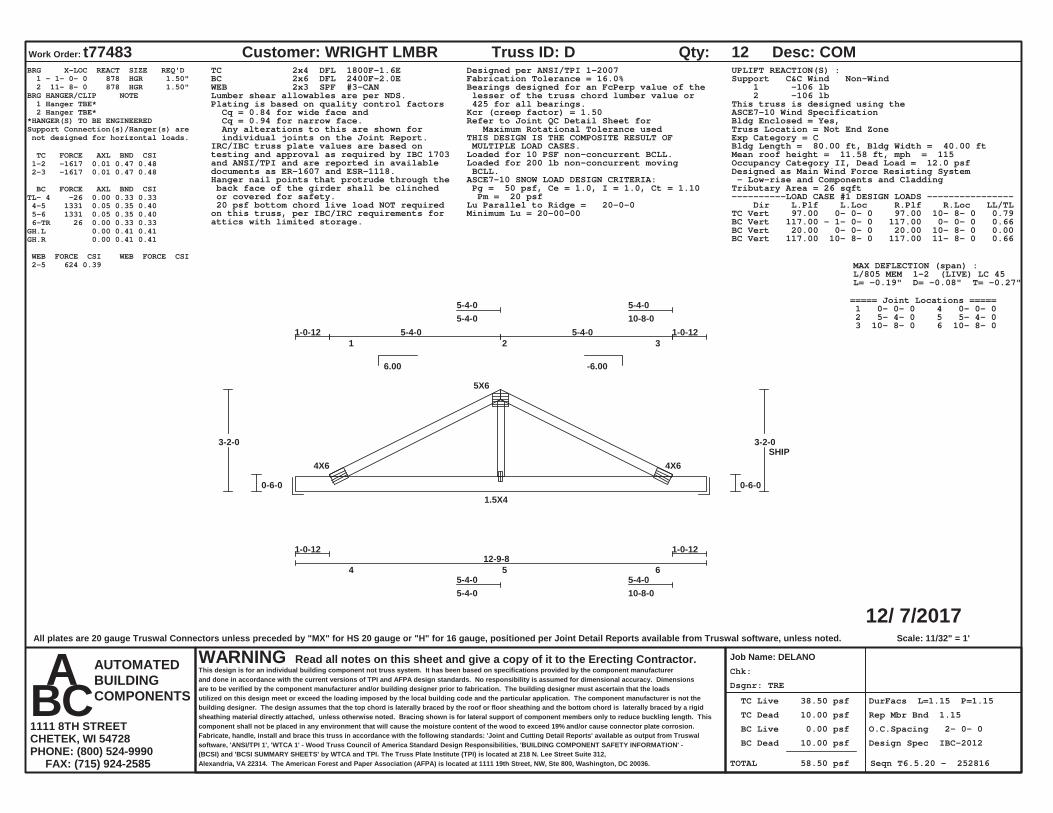
Dsgnr: TRE
Chk:
TC Live 38.50 psf
TC Dead 10.00 psf
BC Live 0.00 psf
BC Dead 10.00 psf
TOTAL 58.50 psf
DurFacs L=1.15 P=1.15
Rep Mbr Bnd 1.15
O.C.Spacing 2- 0- 0
Design Spec IBC-2012
Seqn T6.5.20 - 252816
12/ 7/2017
Work Order: t77483 Customer: WRIGHT LMBR
Job Name: DELANO
Truss ID: D Qty: 12 Desc: COM
WARNING Read all notes on this sheet and give a copy of it to the Erecting Contractor.This design is for an individual building component not truss system. It has been based on specifications provided by the component manufacturerand done in accordance with the current versions of TPI and AFPA design standards. No responsibility is assumed for dimensional accuracy. Dimensionsare to be verified by the component manufacturer and/or building designer prior to fabrication. The building designer must ascertain that the loadsutilized on this design meet or exceed the loading imposed by the local building code and the particular application. The component manufacturer is not thebuilding designer. The design assumes that the top chord is laterally braced by the roof or floor sheathing and the bottom chord is laterally braced by a rigidsheathing material directly attached, unless otherwise noted. Bracing shown is for lateral support of component members only to reduce buckling length. Thiscomponent shall not be placed in any environment that will cause the moisture content of the wood to exceed 19% and/or cause connector plate corrosion.Fabricate, handle, install and brace this truss in accordance with the following standards: 'Joint and Cutting Detail Reports' available as output from Truswalsoftware, 'ANSI/TPI 1', 'WTCA 1' - Wood Truss Council of America Standard Design Responsibilities, 'BUILDING COMPONENT SAFETY INFORMATION' -(BCSI) and 'BCSI SUMMARY SHEETS' by WTCA and TPI. The Truss Plate Institute (TPI) is located at 218 N. Lee Street Suite 312,Alexandria, VA 22314. The American Forest and Paper Association (AFPA) is located at 1111 19th Street, NW, Ste 800, Washington, DC 20036.
AUTOMATEDBUILDINGCOMPONENTS
A B C 1111 8TH STREETCHETEK, WI 54728PHONE: (800) 524-9990 FAX: (715) 924-2585
6.00 -6.00
Scale: 11/32" = 1'
1 2 3
5-4-05-4-0
5-4-010-8-0
4 5 6 5-4-05-4-0
5-4-010-8-0
4X6
5X6
4X6
1.5X4
12-9-8
0-6-0
3-2-0
0-6-0
3-2-0
1-0-12 1-0-125-4-0 5-4-0
1-0-12 1-0-12
SHIP
BRG X-LOC REACT SIZE REQ'D 1 - 1- 0- 0 878 HGR 1.50" 2 11- 8- 0 878 HGR 1.50"BRG HANGER/CLIP NOTE 1 Hanger TBE* 2 Hanger TBE**HANGER(S) TO BE ENGINEEREDSupport Connection(s)/Hanger(s) are not designed for horizontal loads.
TC FORCE AXL BND CSI 1-2 -1617 0.01 0.47 0.48 2-3 -1617 0.01 0.47 0.48
BC FORCE AXL BND CSITL- 4 -26 0.00 0.33 0.33 4-5 1331 0.05 0.35 0.40 5-6 1331 0.05 0.35 0.40 6-TR 26 0.00 0.33 0.33GH.L 0.00 0.41 0.41GH.R 0.00 0.41 0.41
WEB FORCE CSI WEB FORCE CSI 2-5 624 0.39
TC 2x4 DFL 1800F-1.6EBC 2x6 DFL 2400F-2.0EWEB 2x3 SPF #3-CANLumber shear allowables are per NDS.
Designed per ANSI/TPI 1-2007Fabrication Tolerance = 16.0%Bearings designed for an FcPerp value of the lesser of the truss chord lumber value or 425 for all bearings.Plating is based on quality control factors
Cq = 0.84 for wide face and Cq = 0.94 for narrow face. Any alterations to this are shown for individual joints on the Joint Report.
Kcr (creep factor) = 1.50Refer to Joint QC Detail Sheet for Maximum Rotational Tolerance usedTHIS DESIGN IS THE COMPOSITE RESULT OF MULTIPLE LOAD CASES.IRC/IBC truss plate values are based on
testing and approval as required by IBC 1703and ANSI/TPI and are reported in availabledocuments as ER-1607 and ESR-1118.
Loaded for 10 PSF non-concurrent BCLL.Loaded for 200 lb non-concurrent moving BCLL.ASCE7-10 SNOW LOAD DESIGN CRITERIA: Pg = 50 psf, Ce = 1.0, I = 1.0, Ct = 1.10 Pm = 20 psfLu Parallel to Ridge = 20-0-0Minimum Lu = 20-00-00
Hanger nail points that protrude through the back face of the girder shall be clinched or covered for safety.
UPLIFT REACTION(S) :Support C&C Wind Non-Wind 1 -106 lb 2 -106 lbThis truss is designed using theASCE7-10 Wind SpecificationBldg Enclosed = Yes,Truss Location = Not End ZoneExp Category = CBldg Length = 80.00 ft, Bldg Width = 40.00 ftMean roof height = 11.58 ft, mph = 115Occupancy Category II, Dead Load = 12.0 psfDesigned as Main Wind Force Resisting System - Low-rise and Components and CladdingTributary Area = 26 sqft
20 psf bottom chord live load NOT requiredon this truss, per IBC/IRC requirements forattics with limited storage.
----------LOAD CASE #1 DESIGN LOADS ---------------- Dir L.Plf L.Loc R.Plf R.Loc LL/TLTC Vert 97.00 0- 0- 0 97.00 10- 8- 0 0.79BC Vert 117.00 - 1- 0- 0 117.00 0- 0- 0 0.66BC Vert 20.00 0- 0- 0 20.00 10- 8- 0 0.00BC Vert 117.00 10- 8- 0 117.00 11- 8- 0 0.66
MAX DEFLECTION (span) :L/805 MEM 1-2 (LIVE) LC 45L= -0.19" D= -0.08" T= -0.27"
===== Joint Locations ===== 1 0- 0- 0 4 0- 0- 0 2 5- 4- 0 5 5- 4- 0 3 10- 8- 0 6 10- 8- 0
All plates are 20 gauge Truswal Connectors unless preceded by "MX" for HS 20 gauge or "H" for 16 gauge, positioned per Joint Detail Reports available from Truswal software, unless noted.
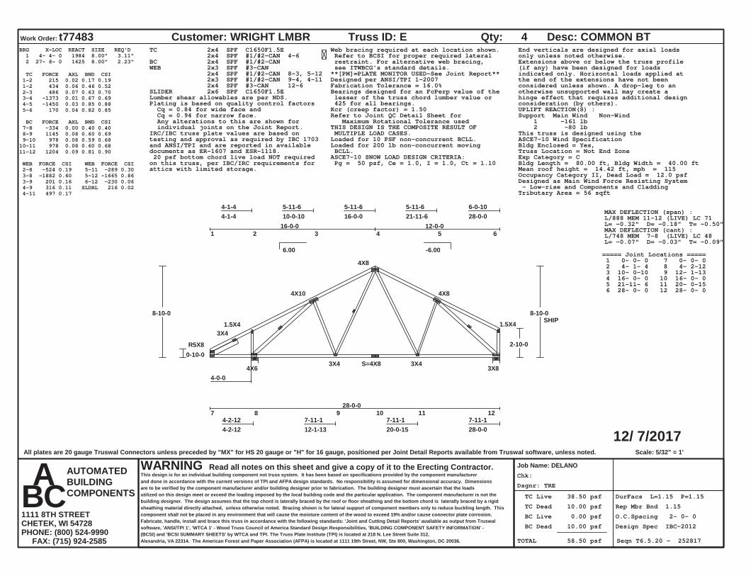
Dsgnr: TRE
Chk:
TC Live 38.50 psf
TC Dead 10.00 psf
BC Live 0.00 psf
BC Dead 10.00 psf
TOTAL 58.50 psf
DurFacs L=1.15 P=1.15
Rep Mbr Bnd 1.15
O.C.Spacing 2- 0- 0
Design Spec IBC-2012
Seqn T6.5.20 - 252817
12/ 7/2017
Work Order: t77483 Customer: WRIGHT LMBR
Job Name: DELANO
Truss ID: E Qty: 4 Desc: COMMON BT
WARNING Read all notes on this sheet and give a copy of it to the Erecting Contractor.This design is for an individual building component not truss system. It has been based on specifications provided by the component manufacturerand done in accordance with the current versions of TPI and AFPA design standards. No responsibility is assumed for dimensional accuracy. Dimensionsare to be verified by the component manufacturer and/or building designer prior to fabrication. The building designer must ascertain that the loadsutilized on this design meet or exceed the loading imposed by the local building code and the particular application. The component manufacturer is not thebuilding designer. The design assumes that the top chord is laterally braced by the roof or floor sheathing and the bottom chord is laterally braced by a rigidsheathing material directly attached, unless otherwise noted. Bracing shown is for lateral support of component members only to reduce buckling length. Thiscomponent shall not be placed in any environment that will cause the moisture content of the wood to exceed 19% and/or cause connector plate corrosion.Fabricate, handle, install and brace this truss in accordance with the following standards: 'Joint and Cutting Detail Reports' available as output from Truswalsoftware, 'ANSI/TPI 1', 'WTCA 1' - Wood Truss Council of America Standard Design Responsibilities, 'BUILDING COMPONENT SAFETY INFORMATION' -(BCSI) and 'BCSI SUMMARY SHEETS' by WTCA and TPI. The Truss Plate Institute (TPI) is located at 218 N. Lee Street Suite 312,Alexandria, VA 22314. The American Forest and Paper Association (AFPA) is located at 1111 19th Street, NW, Ste 800, Washington, DC 20036.
AUTOMATEDBUILDINGCOMPONENTS
A B C 1111 8TH STREETCHETEK, WI 54728PHONE: (800) 524-9990 FAX: (715) 924-2585
6.00 -6.00
Scale: 5/32" = 1'
1 2 3 4 5 6
4-1-44-1-4
5-11-610-0-10
5-11-616-0-0
5-11-621-11-6
6-0-1028-0-0
7 8 9 10 11 124-2-124-2-12
7-11-112-1-13
7-11-120-0-15
7-11-128-0-0
R5X8
1.5X4
4X10
4X8
4X8
1.5X4
4X63X4 S=4X8 3X4
3X8
3X4
4-0-0
28-0-0
0-10-0
8-10-0
2-10-0
8-10-0
16-0-0 12-0-0
SHIP
BRG X-LOC REACT SIZE REQ'D 1 4- 4- 0 1984 8.00" 3.11" 2 27- 8- 0 1425 8.00" 2.23"
TC FORCE AXL BND CSI 1-2 215 0.02 0.17 0.19 1-2 434 0.06 0.46 0.52 2-3 486 0.07 0.63 0.70 3-4 -1373 0.01 0.67 0.69 4-5 -1450 0.03 0.85 0.88 5-6 170 0.04 0.82 0.85
BC FORCE AXL BND CSI 7-8 -334 0.00 0.40 0.40 8-9 1145 0.08 0.60 0.69 9-10 978 0.08 0.59 0.6810-11 978 0.08 0.60 0.6811-12 1204 0.09 0.81 0.90
WEB FORCE CSI WEB FORCE CSI 2-8 -524 0.19 3-8 -1882 0.60 3-9 201 0.16 4-9 316 0.11 4-11 497 0.17
5-11 -289 0.30 5-12 -1665 0.86 6-12 -230 0.06 SLDRL 216 0.02
TC 2x4 SPF C1650F1.5E 2x4 SPF #1/#2-CAN 4-6BC 2x4 SPF #1/#2-CANWEB 2x3 SPF #3-CAN 2x4 SPF #1/#2-CAN 8-3, 5-12 2x3 SPF #1/#2-CAN 9-4, 4-11 2x4 SPF #3-CAN 12-6SLIDER 2x6 SPF C1650F1.5ELumber shear allowables are per NDS.
Web bracing required at each location shown. Refer to BCSI for proper required lateral restraint. For alternative web bracing, see ITWBCG's standard details.**[PM]=PLATE MONITOR USED-See Joint Report**Designed per ANSI/TPI 1-2007Fabrication Tolerance = 16.0%Bearings designed for an FcPerp value of the lesser of the truss chord lumber value or 425 for all bearings.Plating is based on quality control factors
Cq = 0.84 for wide face and Cq = 0.94 for narrow face. Any alterations to this are shown for individual joints on the Joint Report.
Kcr (creep factor) = 1.50Refer to Joint QC Detail Sheet for Maximum Rotational Tolerance usedTHIS DESIGN IS THE COMPOSITE RESULT OF MULTIPLE LOAD CASES.IRC/IBC truss plate values are based on
testing and approval as required by IBC 1703and ANSI/TPI and are reported in availabledocuments as ER-1607 and ESR-1118.
Loaded for 10 PSF non-concurrent BCLL.Loaded for 200 lb non-concurrent moving BCLL.ASCE7-10 SNOW LOAD DESIGN CRITERIA: Pg = 50 psf, Ce = 1.0, I = 1.0, Ct = 1.10
End verticals are designed for axial loadsonly unless noted otherwise.Extensions above or below the truss profile(if any) have been designed for loadsindicated only. Horizontal loads applied atthe end of the extensions have not beenconsidered unless shown. A drop-leg to anotherwise unsupported wall may create ahinge effect that requires additional designconsideration (by others).UPLIFT REACTION(S) :Support Main Wind Non-Wind 1 -161 lb 2 -80 lbThis truss is designed using theASCE7-10 Wind SpecificationBldg Enclosed = Yes,Truss Location = Not End ZoneExp Category = CBldg Length = 80.00 ft, Bldg Width = 40.00 ftMean roof height = 14.42 ft, mph = 115Occupancy Category II, Dead Load = 12.0 psfDesigned as Main Wind Force Resisting System - Low-rise and Components and CladdingTributary Area = 56 sqft
20 psf bottom chord live load NOT requiredon this truss, per IBC/IRC requirements forattics with limited storage.
MAX DEFLECTION (span) :L/888 MEM 11-12 (LIVE) LC 71L= -0.32" D= -0.18" T= -0.50"MAX DEFLECTION (cant) :L/748 MEM 7-8 (LIVE) LC 48L= -0.07" D= -0.03" T= -0.09"
===== Joint Locations ===== 1 0- 0- 0 7 0- 0- 0 2 4- 1- 4 8 4- 2-12 3 10- 0-10 9 12- 1-13 4 16- 0- 0 10 16- 0- 0 5 21-11- 6 11 20- 0-15 6 28- 0- 0 12 28- 0- 0
All plates are 20 gauge Truswal Connectors unless preceded by "MX" for HS 20 gauge or "H" for 16 gauge, positioned per Joint Detail Reports available from Truswal software, unless noted.
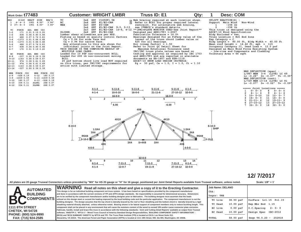
Dsgnr: TRE
Chk:
TC Live 38.50 psf
TC Dead 10.00 psf
BC Live 0.00 psf
BC Dead 10.00 psf
TOTAL 58.50 psf
DurFacs L=1.15 P=1.15
Rep Mbr Bnd 1.15
O.C.Spacing 2- 0- 0
Design Spec IBC-2012
Seqn T6.5.20 - 252818
12/ 7/2017
Work Order: t77483 Customer: WRIGHT LMBR
Job Name: DELANO
Truss ID: E1 Qty: 1 Desc: COM
WARNING Read all notes on this sheet and give a copy of it to the Erecting Contractor.This design is for an individual building component not truss system. It has been based on specifications provided by the component manufacturerand done in accordance with the current versions of TPI and AFPA design standards. No responsibility is assumed for dimensional accuracy. Dimensionsare to be verified by the component manufacturer and/or building designer prior to fabrication. The building designer must ascertain that the loadsutilized on this design meet or exceed the loading imposed by the local building code and the particular application. The component manufacturer is not thebuilding designer. The design assumes that the top chord is laterally braced by the roof or floor sheathing and the bottom chord is laterally braced by a rigidsheathing material directly attached, unless otherwise noted. Bracing shown is for lateral support of component members only to reduce buckling length. Thiscomponent shall not be placed in any environment that will cause the moisture content of the wood to exceed 19% and/or cause connector plate corrosion.Fabricate, handle, install and brace this truss in accordance with the following standards: 'Joint and Cutting Detail Reports' available as output from Truswalsoftware, 'ANSI/TPI 1', 'WTCA 1' - Wood Truss Council of America Standard Design Responsibilities, 'BUILDING COMPONENT SAFETY INFORMATION' -(BCSI) and 'BCSI SUMMARY SHEETS' by WTCA and TPI. The Truss Plate Institute (TPI) is located at 218 N. Lee Street Suite 312,Alexandria, VA 22314. The American Forest and Paper Association (AFPA) is located at 1111 19th Street, NW, Ste 800, Washington, DC 20036.
AUTOMATEDBUILDINGCOMPONENTS
A B C 1111 8TH STREETCHETEK, WI 54728PHONE: (800) 524-9990 FAX: (715) 924-2585
6.00 -6.00
Scale: 1/8" = 1'
1 2 3 4 5 6 7
4-1-44-1-4
5-11-610-0-10
5-11-616-0-0
5-11-621-11-6
5-11-627-10-12
4-1-432-0-0
8 9 10 11 12 13 144-1-44-1-4
7-11-312-0-7
7-11-319-11-9
7-11-327-10-12
4-1-432-0-0
R5X8
1.5X4
4X10
4X8
4X10
1.5X4
R5X8
4X6 3X4 S=4X8 3X4 4X6
3X4 3X4
4-0-0 4-0-0
32-0-0
0-10-0
8-10-0
0-10-0
8-10-0
16-0-0 16-0-0
SHIP
BRG X-LOC REACT SIZE REQ'D 1 4- 4- 0 1951 8.00" 3.06" 2 27- 8- 0 1951 8.00" 3.06"
TC FORCE AXL BND CSI 1-2 171 0.01 0.19 0.20 1-2 438 0.06 0.40 0.46 2-3 488 0.07 0.76 0.83 3-4 -1373 0.01 0.66 0.68 4-5 -1373 0.01 0.66 0.68 5-6 488 0.07 0.76 0.83 6-7 438 0.06 0.40 0.46 6-7 170 0.01 0.19 0.20
BC FORCE AXL BND CSI 8-9 -337 0.00 0.39 0.39 9-10 1143 0.08 0.59 0.6710-11 974 0.08 0.61 0.6911-12 974 0.08 0.61 0.6912-13 1143 0.08 0.59 0.6713-14 -337 0.00 0.39 0.39
WEB FORCE CSI WEB FORCE CSI 2-9 -528 0.19 3-9 -1839 0.59 3-10 180 0.17 4-10 334 0.11 4-12 334 0.11
5-12 180 0.17 5-13 -1839 0.59 6-13 -528 0.19 SLDRL 268 0.07 SLDRR 268 0.07
TC 2x4 SPF C1650F1.5EBC 2x4 SPF #1/#2-CANWEB 2x3 SPF #3-CAN 2x4 SPF #1/#2-CAN 9-3, 5-13 2x3 SPF #1/#2-CAN 10-4, 4-12SLIDER 2x4 SPF #1/#2-CANLumber shear allowables are per NDS.
Web bracing required at each location shown. Refer to BCSI for proper required lateral restraint. For alternative web bracing, see ITWBCG's standard details.**[PM]=PLATE MONITOR USED-See Joint Report**Designed per ANSI/TPI 1-2007Fabrication Tolerance = 16.0%Bearings designed for an FcPerp value of the lesser of the truss chord lumber value or 425 for all bearings.
Plating is based on quality control factors Cq = 0.84 for wide face and Cq = 0.94 for narrow face. Any alterations to this are shown for individual joints on the Joint Report.
Kcr (creep factor) = 1.50Refer to Joint QC Detail Sheet for Maximum Rotational Tolerance usedTHIS DESIGN IS THE COMPOSITE RESULT OF
MULTIPLE LOAD CASES. IRC/IBC truss plate values are based ontesting and approval as required by IBC 1703and ANSI/TPI and are reported in availabledocuments as ER-1607 and ESR-1118.
Loaded for 10 PSF non-concurrent BCLL.Loaded for 200 lb non-concurrent moving BCLL.
ASCE7-10 SNOW LOAD DESIGN CRITERIA: Pg = 50 psf, Ce = 1.0, I = 1.0, Ct = 1.10
UPLIFT REACTION(S) :Support Main Wind Non-Wind 1 -158 lb 2 -158 lbThis truss is designed using theASCE7-10 Wind SpecificationBldg Enclosed = Yes,Truss Location = Not End ZoneExp Category = CBldg Length = 80.00 ft, Bldg Width = 40.00 ftMean roof height = 14.42 ft, mph = 115Occupancy Category II, Dead Load = 12.0 psfDesigned as Main Wind Force Resisting System - Low-rise and Components and CladdingTributary Area = 64 sqft
20 psf bottom chord live load NOT requiredon this truss, per IBC/IRC requirements forattics with limited storage.
MAX DEFLECTION (span) :L/987 MEM 3-4 (LIVE) LC 49L= -0.28" D= -0.07" T= -0.35"MAX DEFLECTION (cant) :L/729 MEM 13-14 (LIVE) LC 81L= -0.07" D= -0.02" T= -0.09"
===== Joint Locations ===== 1 0- 0- 0 8 0- 0- 0 2 4- 1- 4 9 4- 1- 4 3 10- 0-10 10 12- 0- 7 4 16- 0- 0 11 16- 0- 0 5 21-11- 6 12 19-11- 9 6 27-10-12 13 27-10-12 7 32- 0- 0 14 32- 0- 0
All plates are 20 gauge Truswal Connectors unless preceded by "MX" for HS 20 gauge or "H" for 16 gauge, positioned per Joint Detail Reports available from Truswal software, unless noted.

Dsgnr: TRE
Chk:
TC Live 38.50 psf
TC Dead 10.00 psf
BC Live 0.00 psf
BC Dead 10.00 psf
TOTAL 58.50 psf
DurFacs L=1.15 P=1.15
Rep Mbr Bnd 1.10
O.C.Spacing 2- 0- 0
Design Spec IBC-2012
Seqn T6.5.20 - 252819
12/ 7/2017
Work Order: t77483 Customer: WRIGHT LMBR
Job Name: DELANO
Truss ID: E2 Qty: 1 Desc:
WARNING Read all notes on this sheet and give a copy of it to the Erecting Contractor.This design is for an individual building component not truss system. It has been based on specifications provided by the component manufacturerand done in accordance with the current versions of TPI and AFPA design standards. No responsibility is assumed for dimensional accuracy. Dimensionsare to be verified by the component manufacturer and/or building designer prior to fabrication. The building designer must ascertain that the loadsutilized on this design meet or exceed the loading imposed by the local building code and the particular application. The component manufacturer is not thebuilding designer. The design assumes that the top chord is laterally braced by the roof or floor sheathing and the bottom chord is laterally braced by a rigidsheathing material directly attached, unless otherwise noted. Bracing shown is for lateral support of component members only to reduce buckling length. Thiscomponent shall not be placed in any environment that will cause the moisture content of the wood to exceed 19% and/or cause connector plate corrosion.Fabricate, handle, install and brace this truss in accordance with the following standards: 'Joint and Cutting Detail Reports' available as output from Truswalsoftware, 'ANSI/TPI 1', 'WTCA 1' - Wood Truss Council of America Standard Design Responsibilities, 'BUILDING COMPONENT SAFETY INFORMATION' -(BCSI) and 'BCSI SUMMARY SHEETS' by WTCA and TPI. The Truss Plate Institute (TPI) is located at 218 N. Lee Street Suite 312,Alexandria, VA 22314. The American Forest and Paper Association (AFPA) is located at 1111 19th Street, NW, Ste 800, Washington, DC 20036.
AUTOMATEDBUILDINGCOMPONENTS
A B C 1111 8TH STREETCHETEK, WI 54728PHONE: (800) 524-9990 FAX: (715) 924-2585
6.00 -6.00
Scale: 1/8" = 1'
1 2 3 4 5 6 7 8
4-1-44-1-4
4-11-09-0-4
4-11-013-11-4
4-1-818-0-12
4-11-022-11-12
4-11-027-10-12
4-1-432-0-0
9 10 11 12 13 14 154-1-44-1-4
7-11-312-0-7
7-11-319-11-9
7-11-327-10-12
4-1-432-0-0
R5X8
1.5X4
4X6
5X6 5X6
4X6
1.5X4
R5X8
4X6 3X4 S=4X8 3X6 5X6
3X4 3X4
4-0-0 4-0-0
32-0-0
0-10-0
7-9-10
0-10-0
7-9-10
13-11-4 4-1-8 13-11-4
7-7-15
SHIP
BRG X-LOC REACT SIZE REQ'D 1 4- 4- 0 2095 8.00" 3.29" 2 27- 8- 0 2095 8.00" 3.29"
TC FORCE AXL BND CSI 1-2 167 0.01 0.23 0.24 1-2 437 0.09 0.53 0.62 2-3 474 0.11 0.51 0.62 3-4 -1349 0.02 0.49 0.52 4-5 -1082 0.01 0.36 0.37 5-6 -1349 0.02 0.50 0.52 6-7 475 0.11 0.52 0.63 7-8 437 0.09 0.53 0.62 7-8 167 0.01 0.24 0.25
BC FORCE AXL BND CSI 9-10 -338 0.00 0.41 0.4110-11 1074 0.07 0.61 0.6811-12 1081 0.09 0.64 0.7312-13 1081 0.09 0.64 0.7313-14 1074 0.07 0.61 0.6914-15 -338 0.00 0.41 0.41
WEB FORCE CSI WEB FORCE CSI 2-10 -553 0.20 3-10 -1873 0.93 3-11 229 0.14 4-11 216 0.12 4-13 -219 0.18 5-13 157 0.10
6-13 231 0.14 6-14 -1873 0.93 7-14 -553 0.20 SLDRL 272 0.07 SLDRR 272 0.07
TC 2x4 SPF #1/#2-CANBC 2x4 SPF #1/#2-CANWEB 2x3 SPF #3-CAN 2x3 SPF #1/#2-CAN 10-3, 4-13 6-14SLIDER 2x4 SPF #1/#2-CANLumber shear allowables are per NDS.
Web bracing required at each location shown. Refer to BCSI for proper required lateral restraint. For alternative web bracing, see ITWBCG's standard details.**[PM]=PLATE MONITOR USED-See Joint Report**Designed per ANSI/TPI 1-2007Fabrication Tolerance = 16.0%Bearings designed for an FcPerp value of the lesser of the truss chord lumber value or 425 for all bearings.
Plating is based on quality control factors Cq = 0.84 for wide face and Cq = 0.94 for narrow face. Any alterations to this are shown for individual joints on the Joint Report.
Kcr (creep factor) = 1.50Refer to Joint QC Detail Sheet for Maximum Rotational Tolerance usedTHIS DESIGN IS THE COMPOSITE RESULT OF
MULTIPLE LOAD CASES. IRC/IBC truss plate values are based ontesting and approval as required by IBC 1703and ANSI/TPI and are reported in availabledocuments as ER-1607 and ESR-1118.
Loaded for 10 PSF non-concurrent BCLL.Loaded for 200 lb non-concurrent moving BCLL.
ASCE7-10 SNOW LOAD DESIGN CRITERIA: Pg = 50 psf, Ce = 1.0, I = 1.0, Ct = 1.10 Pm = 20 psfLu Parallel to Ridge = 20-0-0Minimum Lu = 20-00-00
Drainage must be provided to avoid ponding.
This design based on chord bracing appliedper the following schedule: max o.c. from to TC 24.00" 13-11- 4 18- 0-12UPLIFT REACTION(S) :Support Main Wind Non-Wind 1 -158 lb 2 -158 lbHip-Drop : 0-1-11This truss is designed using theASCE7-10 Wind SpecificationBldg Enclosed = Yes,Truss Location = Not End ZoneExp Category = CBldg Length = 80.00 ft, Bldg Width = 40.00 ftMean roof height = 13.90 ft, mph = 115Occupancy Category II, Dead Load = 12.0 psfDesigned as Main Wind Force Resisting System - Low-rise and Components and CladdingTributary Area = 64 sqft
20 psf bottom chord live load NOT requiredon this truss, per IBC/IRC requirements forattics with limited storage.
MAX DEFLECTION (span) :L/999 MEM 11-12 (LIVE) LC 73L= -0.26" D= -0.12" T= -0.38"MAX DEFLECTION (cant) :L/731 MEM 9-10 (LIVE) LC 59L= -0.07" D= -0.03" T= -0.10"
===== Joint Locations ===== 1 0- 0- 0 9 0- 0- 0 2 4- 1- 4 10 4- 1- 4 3 9- 0- 4 11 12- 0- 7 4 13-11- 4 12 16- 0- 0 5 18- 0-12 13 19-11- 9 6 22-11-12 14 27-10-12 7 27-10-12 15 32- 0- 0 8 32- 0- 0
All plates are 20 gauge Truswal Connectors unless preceded by "MX" for HS 20 gauge or "H" for 16 gauge, positioned per Joint Detail Reports available from Truswal software, unless noted.

Dsgnr: TRE
Chk:
TC Live 38.50 psf
TC Dead 10.00 psf
BC Live 0.00 psf
BC Dead 10.00 psf
TOTAL 58.50 psf
DurFacs L=1.15 P=1.15
Rep Mbr Bnd 1.00
O.C.Spacing 2- 0- 0
Design Spec IBC-2012
Seqn T6.5.20 - 252820
12/ 7/2017
Work Order: t77483 Customer: WRIGHT LMBR
Job Name: DELANO
Truss ID: E3 Qty: 1 Desc: HIP GIRDER
WARNING Read all notes on this sheet and give a copy of it to the Erecting Contractor.This design is for an individual building component not truss system. It has been based on specifications provided by the component manufacturerand done in accordance with the current versions of TPI and AFPA design standards. No responsibility is assumed for dimensional accuracy. Dimensionsare to be verified by the component manufacturer and/or building designer prior to fabrication. The building designer must ascertain that the loadsutilized on this design meet or exceed the loading imposed by the local building code and the particular application. The component manufacturer is not thebuilding designer. The design assumes that the top chord is laterally braced by the roof or floor sheathing and the bottom chord is laterally braced by a rigidsheathing material directly attached, unless otherwise noted. Bracing shown is for lateral support of component members only to reduce buckling length. Thiscomponent shall not be placed in any environment that will cause the moisture content of the wood to exceed 19% and/or cause connector plate corrosion.Fabricate, handle, install and brace this truss in accordance with the following standards: 'Joint and Cutting Detail Reports' available as output from Truswalsoftware, 'ANSI/TPI 1', 'WTCA 1' - Wood Truss Council of America Standard Design Responsibilities, 'BUILDING COMPONENT SAFETY INFORMATION' -(BCSI) and 'BCSI SUMMARY SHEETS' by WTCA and TPI. The Truss Plate Institute (TPI) is located at 218 N. Lee Street Suite 312,Alexandria, VA 22314. The American Forest and Paper Association (AFPA) is located at 1111 19th Street, NW, Ste 800, Washington, DC 20036.
AUTOMATEDBUILDINGCOMPONENTS
A B C 1111 8TH STREETCHETEK, WI 54728PHONE: (800) 524-9990 FAX: (715) 924-2585
6.00 -6.00
Scale: 1/8" = 1'
1 2 3 4 5 6 7
5-11-105-11-10
5-11-1011-11-4
4-0-1216-0-0
4-0-1220-0-12
5-11-1026-0-6
5-11-1032-0-0
8 9 10 11 12 13 144-3-124-3-12
7-7-811-11-4
8-1-820-0-12
7-7-827-8-4
4-3-1232-0-0
TYPICAL PLATE : 8X8
6X12
6X6 3X4 6X6
6X12
4X10 7X16 S=SS05147X16
4X10
1.5X4 1.5X4
4-0-0 4-0-0
32-0-0
0-10-0
6-9-10
0-10-0
6-9-10
11-11-4 8-1-8 11-11-4
4-0-0480# 0-0-12
14-0-0
16-0-0
18-0-0
480# 31-11-4
12-0-0
14-0-0
16-0-0
18-0-0
20-0-0
6-7-15
SHIP
BRG X-LOC REACT SIZE REQ'D 1 4- 4- 0 4685 8.00" 7.35" 2 27- 8- 0 4685 8.00" 7.35"
TC FORCE AXL BND CSI 1-2 1437 0.12 0.79 0.91 2-3 -4310 0.01 0.60 0.61 3-4 -3800 0.22 0.50 0.72 4-5 -3800 0.22 0.50 0.72 5-6 -4310 0.01 0.60 0.61 6-7 1436 0.12 0.79 0.91
BC FORCE AXL BND CSI 8-9 -1106 0.00 0.28 0.28 9-10 1523 0.09 0.33 0.4210-11 4120 0.42 0.32 0.7411-12 4120 0.42 0.32 0.7412-13 1523 0.09 0.33 0.4213-14 -1106 0.00 0.28 0.29
WEB FORCE CSI WEB FORCE CSI 2-9 -4764 1.00 2-10 2901 0.79 3-10 1301 0.71 4-10 -761 0.71
4-12 -762 0.71 5-12 1301 0.71 6-12 2901 0.79 6-13 -4764 1.00
TC 2x4 DFL 2400F-2.0E 2x4 SPF C1650F1.5E 3-5BC 2x6 SPF C1650F1.5EWEB 2x4 SPF #1/#2-CAN 2x4 SPF #3-CAN 10-3, 12-5WEDGE 2x6 SPF C1650F1.5EGBL BLK 2x3 SPF #3-CANLumber shear allowables are per NDS.
Web bracing required at each location shown. Refer to BCSI for proper required lateral restraint. For alternative web bracing, see ITWBCG's standard details.**[PM]=PLATE MONITOR USED-See Joint Report**Designed per ANSI/TPI 1-2007Fabrication Tolerance = 16.0%Bearings designed for an FcPerp value of the lesser of the truss chord lumber value or 425 for all bearings.
Plating is based on quality control factors Cq = 0.84 for wide face and Cq = 0.94 for narrow face. Any alterations to this are shown for individual joints on the Joint Report.
Kcr (creep factor) = 1.50Refer to Joint QC Detail Sheet for Maximum Rotational Tolerance usedTHIS DESIGN IS THE COMPOSITE RESULT OF MULTIPLE LOAD CASES.
IRC/IBC truss plate values are based ontesting and approval as required by IBC 1703and ANSI/TPI and are reported in availabledocuments as ER-1607 and ESR-1118.
Loaded for 10 PSF non-concurrent BCLL.Loaded for 200 lb non-concurrent moving BCLL.Heel plates analyzed for eccentricity.ASCE7-10 SNOW LOAD DESIGN CRITERIA: Pg = 50 psf, Ce = 1.0, I = 1.0, Ct = 1.10 Pm = 20 psfLu Parallel to Ridge = 20-0-0Minimum Lu = 20-00-00
Drainage must be provided to avoid ponding.Permanent bracing is required (by others) to prevent rotation/toppling. See BCSI and ANSI/TPI 1.
Gable verticals are 2x 3 web material spaced at 16.0 " o.c. unless noted otherwise.Top chord supports 24.0 " of uniform load at 39 psf live load and 10 psf dead load. Additional design considerations may be required if sheathing is attached.Brace gable studs in accordance with Truswal Systems standard gable bracing details and charts.This truss requires adequate sheathing, as designed by others, applied to the truss face providing lateral support for webs in the truss plane and creating shear wall action to resist diaphragm loads.This design based on chord bracing appliedper the following schedule: max o.c. from to TC 24.00" 11-11- 4 20- 0-12UPLIFT REACTION(S) :Support Main Wind Non-Wind 1 -548 lb -905 lb 2 -549 lb -905 lbDue to high uplift reaction, this truss requires special connection details (designed by others) to secure truss to a rigidly anchored support.
Hip-Drop : 0-1-11This truss is designed using theASCE7-10 Wind SpecificationBldg Enclosed = Yes,Truss Location = Not End ZoneExp Category = CBldg Length = 80.00 ft, Bldg Width = 40.00 ftMean roof height = 13.40 ft, mph = 115Occupancy Category II, Dead Load = 12.0 psfDesigned as Main Wind Force Resisting System - Low-rise and Components and CladdingTributary Area = 95 sqft
20 psf bottom chord live load NOT requiredon this truss, per IBC/IRC requirements forattics with limited storage.
----------LOAD CASE #1 DESIGN LOADS ---------------- Dir L.Plf L.Loc R.Plf R.Loc LL/TLTC Vert 97.00 0- 0- 0 97.00 13- 0- 0 0.79TC Vert 48.50 13- 0- 0 48.50 19- 0- 0 0.79TC Vert 97.00 19- 0- 0 97.00 32- 0- 0 0.79BC Vert 20.00 0- 0- 0 20.00 11- 0- 0 0.00BC Vert 10.00 11- 0- 0 10.00 21- 0- 1 0.00BC Vert 20.00 21- 0- 1 20.00 32- 0- 0 0.00...Type... lbs X.Loc LL/TL FastenerTC Vert 480.0 0- 0-12 0.70TC Vert 480.0 31-11- 4 0.70------------ CRITICAL POINT LOADS ------------------ Type X.Loc Max/Dur Min/DurTC Vert 14- 0- 0 320/1.15 -128/1.60TC Vert 16- 0- 0 320/1.15 -128/1.60TC Vert 18- 0- 0 320/1.15 -128/1.60BC Vert 12- 0- 0 315/1.15 -268/1.15BC Vert 12- 0- 1 1209/1.15 -976/1.15BC Vert 14- 0- 0 106/1.25 -2/1.15BC Vert 16- 0- 0 106/1.25 -2/1.15BC Vert 18- 0- 0 106/1.25 -2/1.15BC Vert 20- 0- 0 315/1.15 -268/1.15BC Vert 20- 0- 1 1209/1.15 -976/1.15
MAX DEFLECTION (span) :L/999 MEM 10-11 (LIVE) LC 66L= -0.24" D= -0.09" T= -0.33"MAX DEFLECTION (cant) :L/250 MEM 1-2 (LIVE) LC 74L= -0.21" D= -0.10" T= -0.31"
===== Joint Locations ===== 1 0- 0- 0 8 0- 0- 0 2 5-11-10 9 4- 3-12 3 11-11- 4 10 11-11- 4 4 16- 0- 0 11 16- 0- 0 5 20- 0-12 12 20- 0-12 6 26- 0- 6 13 27- 8- 4 7 32- 0- 0 14 32- 0- 0
All plates are 20 gauge Truswal Connectors unless preceded by "MX" for HS 20 gauge or "H" for 16 gauge, positioned per Joint Detail Reports available from Truswal software, unless noted.
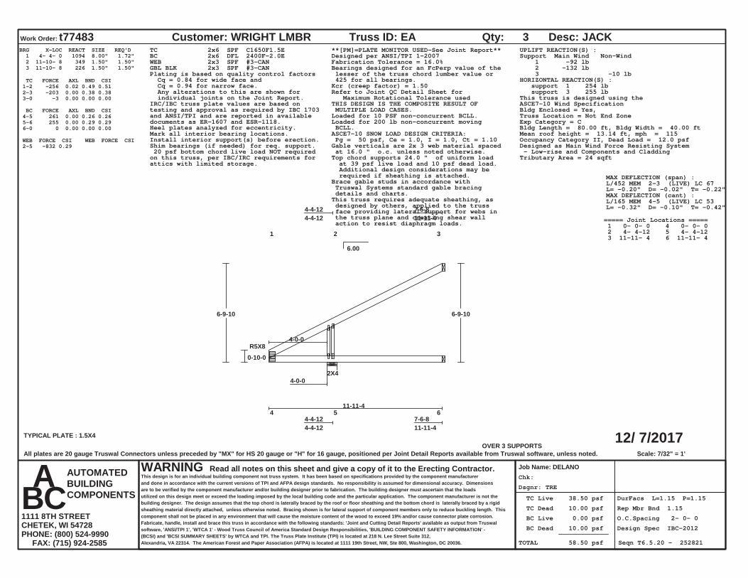
Dsgnr: TRE
Chk:
TC Live 38.50 psf
TC Dead 10.00 psf
BC Live 0.00 psf
BC Dead 10.00 psf
TOTAL 58.50 psf
DurFacs L=1.15 P=1.15
Rep Mbr Bnd 1.15
O.C.Spacing 2- 0- 0
Design Spec IBC-2012
Seqn T6.5.20 - 252821
12/ 7/2017
Work Order: t77483 Customer: WRIGHT LMBR
Job Name: DELANO
Truss ID: EA Qty: 3 Desc: JACK
WARNING Read all notes on this sheet and give a copy of it to the Erecting Contractor.This design is for an individual building component not truss system. It has been based on specifications provided by the component manufacturerand done in accordance with the current versions of TPI and AFPA design standards. No responsibility is assumed for dimensional accuracy. Dimensionsare to be verified by the component manufacturer and/or building designer prior to fabrication. The building designer must ascertain that the loadsutilized on this design meet or exceed the loading imposed by the local building code and the particular application. The component manufacturer is not thebuilding designer. The design assumes that the top chord is laterally braced by the roof or floor sheathing and the bottom chord is laterally braced by a rigidsheathing material directly attached, unless otherwise noted. Bracing shown is for lateral support of component members only to reduce buckling length. Thiscomponent shall not be placed in any environment that will cause the moisture content of the wood to exceed 19% and/or cause connector plate corrosion.Fabricate, handle, install and brace this truss in accordance with the following standards: 'Joint and Cutting Detail Reports' available as output from Truswalsoftware, 'ANSI/TPI 1', 'WTCA 1' - Wood Truss Council of America Standard Design Responsibilities, 'BUILDING COMPONENT SAFETY INFORMATION' -(BCSI) and 'BCSI SUMMARY SHEETS' by WTCA and TPI. The Truss Plate Institute (TPI) is located at 218 N. Lee Street Suite 312,Alexandria, VA 22314. The American Forest and Paper Association (AFPA) is located at 1111 19th Street, NW, Ste 800, Washington, DC 20036.
AUTOMATEDBUILDINGCOMPONENTS
A B C 1111 8TH STREETCHETEK, WI 54728PHONE: (800) 524-9990 FAX: (715) 924-2585
6.00
OVER 3 SUPPORTSScale: 7/32" = 1'
1 2 3
4-4-124-4-12
7-6-811-11-4
4 5 6 4-4-124-4-12
7-6-811-11-4
TYPICAL PLATE : 1.5X4
R5X8
2X44-0-0
11-11-4
0-10-0
6-9-10 6-9-10
4-0-0
BRG X-LOC REACT SIZE REQ'D 1 4- 4- 0 1094 8.00" 1.72" 2 11-10- 8 349 1.50" 1.50" 3 11-10- 8 226 1.50" 1.50"
TC FORCE AXL BND CSI 1-2 -256 0.02 0.49 0.51 2-3 -203 0.00 0.38 0.38 3-0 -3 0.00 0.00 0.00
BC FORCE AXL BND CSI 4-5 261 0.00 0.26 0.26 5-6 255 0.00 0.29 0.29 6-0 0 0.00 0.00 0.00
WEB FORCE CSI WEB FORCE CSI 2-5 -832 0.29
TC 2x6 SPF C1650F1.5EBC 2x6 DFL 2400F-2.0EWEB 2x3 SPF #3-CANGBL BLK 2x3 SPF #3-CAN
**[PM]=PLATE MONITOR USED-See Joint Report**Designed per ANSI/TPI 1-2007Fabrication Tolerance = 16.0%Bearings designed for an FcPerp value of the lesser of the truss chord lumber value or 425 for all bearings.
Plating is based on quality control factors Cq = 0.84 for wide face and Cq = 0.94 for narrow face. Any alterations to this are shown for individual joints on the Joint Report.
Kcr (creep factor) = 1.50Refer to Joint QC Detail Sheet for Maximum Rotational Tolerance usedTHIS DESIGN IS THE COMPOSITE RESULT OF MULTIPLE LOAD CASES.
IRC/IBC truss plate values are based ontesting and approval as required by IBC 1703and ANSI/TPI and are reported in availabledocuments as ER-1607 and ESR-1118.
Loaded for 10 PSF non-concurrent BCLL.Loaded for 200 lb non-concurrent moving BCLL.Heel plates analyzed for eccentricity.ASCE7-10 SNOW LOAD DESIGN CRITERIA: Pg = 50 psf, Ce = 1.0, I = 1.0, Ct = 1.10
Mark all interior bearing locations.Install interior support(s) before erection.
Gable verticals are 2x 3 web material spaced at 16.0 " o.c. unless noted otherwise.Top chord supports 24.0 " of uniform load at 39 psf live load and 10 psf dead load. Additional design considerations may be required if sheathing is attached.Brace gable studs in accordance with Truswal Systems standard gable bracing details and charts.This truss requires adequate sheathing, as designed by others, applied to the truss face providing lateral support for webs in the truss plane and creating shear wall action to resist diaphragm loads.
Shim bearings (if needed) for req. support.
UPLIFT REACTION(S) :Support Main Wind Non-Wind 1 -92 lb 2 -132 lb 3 -10 lbHORIZONTAL REACTION(S) : support 1 254 lb support 3 255 lbThis truss is designed using theASCE7-10 Wind SpecificationBldg Enclosed = Yes,Truss Location = Not End ZoneExp Category = CBldg Length = 80.00 ft, Bldg Width = 40.00 ftMean roof height = 13.14 ft, mph = 115Occupancy Category II, Dead Load = 12.0 psfDesigned as Main Wind Force Resisting System - Low-rise and Components and CladdingTributary Area = 24 sqft
20 psf bottom chord live load NOT requiredon this truss, per IBC/IRC requirements forattics with limited storage.
MAX DEFLECTION (span) :L/452 MEM 2-3 (LIVE) LC 67L= -0.20" D= -0.02" T= -0.22"MAX DEFLECTION (cant) :L/165 MEM 4-5 (LIVE) LC 53L= -0.32" D= -0.10" T= -0.42"
===== Joint Locations ===== 1 0- 0- 0 4 0- 0- 0 2 4- 4-12 5 4- 4-12 3 11-11- 4 6 11-11- 4
All plates are 20 gauge Truswal Connectors unless preceded by "MX" for HS 20 gauge or "H" for 16 gauge, positioned per Joint Detail Reports available from Truswal software, unless noted.
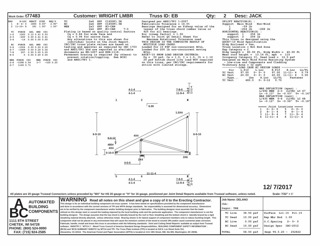
Dsgnr: TRE
Chk:
TC Live 38.50 psf
TC Dead 10.00 psf
BC Live 0.00 psf
BC Dead 10.00 psf
TOTAL 58.50 psf
DurFacs L=1.15 P=1.15
Rep Mbr Bnd 1.00
O.C.Spacing 2- 0- 0
Design Spec IBC-2012
Seqn T6.5.20 - 252822
12/ 7/2017
Work Order: t77483 Customer: WRIGHT LMBR
Job Name: DELANO
Truss ID: EB Qty: 2 Desc: JACK
WARNING Read all notes on this sheet and give a copy of it to the Erecting Contractor.This design is for an individual building component not truss system. It has been based on specifications provided by the component manufacturerand done in accordance with the current versions of TPI and AFPA design standards. No responsibility is assumed for dimensional accuracy. Dimensionsare to be verified by the component manufacturer and/or building designer prior to fabrication. The building designer must ascertain that the loadsutilized on this design meet or exceed the loading imposed by the local building code and the particular application. The component manufacturer is not thebuilding designer. The design assumes that the top chord is laterally braced by the roof or floor sheathing and the bottom chord is laterally braced by a rigidsheathing material directly attached, unless otherwise noted. Bracing shown is for lateral support of component members only to reduce buckling length. Thiscomponent shall not be placed in any environment that will cause the moisture content of the wood to exceed 19% and/or cause connector plate corrosion.Fabricate, handle, install and brace this truss in accordance with the following standards: 'Joint and Cutting Detail Reports' available as output from Truswalsoftware, 'ANSI/TPI 1', 'WTCA 1' - Wood Truss Council of America Standard Design Responsibilities, 'BUILDING COMPONENT SAFETY INFORMATION' -(BCSI) and 'BCSI SUMMARY SHEETS' by WTCA and TPI. The Truss Plate Institute (TPI) is located at 218 N. Lee Street Suite 312,Alexandria, VA 22314. The American Forest and Paper Association (AFPA) is located at 1111 19th Street, NW, Ste 800, Washington, DC 20036.
AUTOMATEDBUILDINGCOMPONENTS
A B C 1111 8TH STREETCHETEK, WI 54728PHONE: (800) 524-9990 FAX: (715) 924-2585
6.00
Scale: 7/32" = 1'
1 2 3 4
4-1-44-1-4
7-8-011-9-4
5 6 7 8 4-1-44-1-4
7-8-011-9-4
4X4
4X4
1.5X4
2X43X6
4-0-0
11-11-4
0-10-0
6-9-10 6-9-10
480# 0-0-12
BRG X-LOC REACT SIZE REQ'D 1 4- 4- 0 1850 8.00" 2.90" 2 11-10- 8 391 1.50" 1.50"
TC FORCE AXL BND CSI 1-2 1263 0.12 0.41 0.53 2-3 -200 0.00 0.41 0.41 3-4 -14 0.00 0.00 0.00
BC FORCE AXL BND CSI 5-6 -1004 0.00 0.20 0.20 6-7 -1089 0.00 0.26 0.26 7-8 257 0.00 0.05 0.05 8-0 0 0.00 0.00 0.00
WEB FORCE CSI WEB FORCE CSI 2-6 -1598 0.54 2-7 1146 0.71 3-7 -335 0.25
TC 2x6 SPF C1650F1.5EBC 2x6 SPF C1650F1.5EWEB 2x3 SPF #3-CAN 2x4 SPF #3-CAN 7-3
Designed per ANSI/TPI 1-2007Fabrication Tolerance = 16.0%Bearings designed for an FcPerp value of the lesser of the truss chord lumber value or 425 for all bearings.Plating is based on quality control factors
Cq = 0.84 for wide face and Cq = 0.94 for narrow face. Any alterations to this are shown for individual joints on the Joint Report.
Kcr (creep factor) = 1.50Refer to Joint QC Detail Sheet for Maximum Rotational Tolerance usedTHIS DESIGN IS THE COMPOSITE RESULT OF MULTIPLE LOAD CASES.IRC/IBC truss plate values are based on
testing and approval as required by IBC 1703and ANSI/TPI and are reported in availabledocuments as ER-1607 and ESR-1118.
Loaded for 10 PSF non-concurrent BCLL.Loaded for 200 lb non-concurrent moving BCLL.ASCE7-10 SNOW LOAD DESIGN CRITERIA: Pg = 50 psf, Ce = 1.0, I = 1.0, Ct = 1.10
Permanent bracing is required (by others) to prevent rotation/toppling. See BCSI and ANSI/TPI 1.
UPLIFT REACTION(S) :Support Main Wind Non-Wind 1 -59 lb 2 -204 lb -268 lbHORIZONTAL REACTION(S) : support 1 256 lb support 2 256 lbThis truss is designed using theASCE7-10 Wind SpecificationBldg Enclosed = Yes,Truss Location = Not End ZoneExp Category = CBldg Length = 80.00 ft, Bldg Width = 40.00 ftMean roof height = 13.14 ft, mph = 115Occupancy Category II, Dead Load = 12.0 psfDesigned as Main Wind Force Resisting System - Low-rise and Components and CladdingTributary Area = 32 sqft
20 psf bottom chord live load NOT requiredon this truss, per IBC/IRC requirements forattics with limited storage.
----------LOAD CASE #1 DESIGN LOADS ---------------- Dir L.Plf L.Loc R.Plf R.Loc LL/TLTC Vert 97.00 0- 0- 0 97.00 11-11- 4 0.79BC Vert 20.00 0- 0- 0 20.00 11-11- 4 0.00...Type... lbs X.Loc LL/TL FastenerTC Vert 480.0 0- 0-12 0.70
MAX DEFLECTION (span) :L/692 MEM 2-3 (LIVE) LC 67L= -0.13" D= -0.03" T= -0.16"MAX DEFLECTION (cant) :L/435 MEM 5-6 (LIVE) LC 68L= -0.12" D= -0.06" T= -0.18"
===== Joint Locations ===== 1 0- 0- 0 5 0- 0- 0 2 4- 1- 4 6 4- 1- 4 3 11- 9- 4 7 11- 9- 4 4 11-11- 4 8 11-11- 4
All plates are 20 gauge Truswal Connectors unless preceded by "MX" for HS 20 gauge or "H" for 16 gauge, positioned per Joint Detail Reports available from Truswal software, unless noted.

Dsgnr: TRE
Chk:
TC Live 38.50 psf
TC Dead 10.00 psf
BC Live 0.00 psf
BC Dead 10.00 psf
TOTAL 58.50 psf
DurFacs L=1.15 P=1.15
Rep Mbr Bnd 1.15
O.C.Spacing 2- 0- 0
Design Spec IBC-2012
Seqn T6.5.20 - 252823
12/ 7/2017
Work Order: t77483 Customer: WRIGHT LMBR
Job Name: DELANO
Truss ID: EC Qty: 4 Desc: JACK CC
WARNING Read all notes on this sheet and give a copy of it to the Erecting Contractor.This design is for an individual building component not truss system. It has been based on specifications provided by the component manufacturerand done in accordance with the current versions of TPI and AFPA design standards. No responsibility is assumed for dimensional accuracy. Dimensionsare to be verified by the component manufacturer and/or building designer prior to fabrication. The building designer must ascertain that the loadsutilized on this design meet or exceed the loading imposed by the local building code and the particular application. The component manufacturer is not thebuilding designer. The design assumes that the top chord is laterally braced by the roof or floor sheathing and the bottom chord is laterally braced by a rigidsheathing material directly attached, unless otherwise noted. Bracing shown is for lateral support of component members only to reduce buckling length. Thiscomponent shall not be placed in any environment that will cause the moisture content of the wood to exceed 19% and/or cause connector plate corrosion.Fabricate, handle, install and brace this truss in accordance with the following standards: 'Joint and Cutting Detail Reports' available as output from Truswalsoftware, 'ANSI/TPI 1', 'WTCA 1' - Wood Truss Council of America Standard Design Responsibilities, 'BUILDING COMPONENT SAFETY INFORMATION' -(BCSI) and 'BCSI SUMMARY SHEETS' by WTCA and TPI. The Truss Plate Institute (TPI) is located at 218 N. Lee Street Suite 312,Alexandria, VA 22314. The American Forest and Paper Association (AFPA) is located at 1111 19th Street, NW, Ste 800, Washington, DC 20036.
AUTOMATEDBUILDINGCOMPONENTS
A B C 1111 8TH STREETCHETEK, WI 54728PHONE: (800) 524-9990 FAX: (715) 924-2585
6.00
OVER 3 SUPPORTSScale: 1/4" = 1'
1 2 3
4-1-44-1-4
5-9-119-10-15
4 5 6 4-1-44-1-4
5-9-119-10-15
3X4
1.5X4
2X44-0-0
9-10-15
0-10-0
5-9-8 5-9-8
BRG X-LOC REACT SIZE REQ'D 1 4- 4- 0 1029 8.00" 1.61" 2 9-10- 3 268 1.50" 1.50" 3 9-10- 3 183 1.50" 1.50"
TC FORCE AXL BND CSI 1-2 -196 0.01 0.39 0.40 2-3 -173 0.00 0.35 0.35 3-0 -3 0.00 0.00 0.00
BC FORCE AXL BND CSI 4-5 209 0.00 0.32 0.32 5-6 224 0.00 0.29 0.29 6-0 0 0.00 0.00 0.00
WEB FORCE CSI WEB FORCE CSI 2-5 -699 0.24
TC 2x6 SPF C1650F1.5EBC 2x6 DFL 2400F-2.0EWEB 2x3 SPF #3-CAN
**[PM]=PLATE MONITOR USED-See Joint Report**Designed per ANSI/TPI 1-2007Fabrication Tolerance = 16.0%Bearings designed for an FcPerp value of the lesser of the truss chord lumber value or 425 for all bearings.
Plating is based on quality control factors Cq = 0.84 for wide face and Cq = 0.94 for narrow face. Any alterations to this are shown for individual joints on the Joint Report.
Kcr (creep factor) = 1.50Refer to Joint QC Detail Sheet for Maximum Rotational Tolerance usedTHIS DESIGN IS THE COMPOSITE RESULT OF
MULTIPLE LOAD CASES. IRC/IBC truss plate values are based ontesting and approval as required by IBC 1703and ANSI/TPI and are reported in availabledocuments as ER-1607 and ESR-1118.
Loaded for 10 PSF non-concurrent BCLL.Loaded for 200 lb non-concurrent moving BCLL.
ASCE7-10 SNOW LOAD DESIGN CRITERIA: Pg = 50 psf, Ce = 1.0, I = 1.0, Ct = 1.10
Mark all interior bearing locations.Install interior support(s) before erection.
Shim bearings (if needed) for req. support.
UPLIFT REACTION(S) :Support C&C Wind Non-Wind 1 -199 lb 2 -138 lb -26 lb 3 -12 lb -71 lbHORIZONTAL REACTION(S) : support 1 223 lb support 3 223 lbThis truss is designed using theASCE7-10 Wind SpecificationBldg Enclosed = Yes,Truss Location = Not End ZoneExp Category = CBldg Length = 80.00 ft, Bldg Width = 40.00 ftMean roof height = 12.64 ft, mph = 115Occupancy Category II, Dead Load = 12.0 psfDesigned as Main Wind Force Resisting System - Low-rise and Components and CladdingTributary Area = 20 sqft
20 psf bottom chord live load NOT requiredon this truss, per IBC/IRC requirements forattics with limited storage.
MAX DEFLECTION (span) :L/999 MEM 2-3 (LIVE) LC 65L= -0.06" D= -0.01" T= -0.07"MAX DEFLECTION (cant) :L/190 MEM 4-5 (LIVE) LC 53L= -0.27" D= -0.15" T= -0.42"
===== Joint Locations ===== 1 0- 0- 0 4 0- 0- 0 2 4- 1- 4 5 4- 1- 4 3 9-10-15 6 9-10-15
All plates are 20 gauge Truswal Connectors unless preceded by "MX" for HS 20 gauge or "H" for 16 gauge, positioned per Joint Detail Reports available from Truswal software, unless noted.

Dsgnr: TRE
Chk:
TC Live 38.50 psf
TC Dead 10.00 psf
BC Live 0.00 psf
BC Dead 10.00 psf
TOTAL 58.50 psf
DurFacs L=1.15 P=1.15
Rep Mbr Bnd 1.15
O.C.Spacing 2- 0- 0
Design Spec IBC-2012
Seqn T6.5.20 - 252824
12/ 7/2017
Work Order: t77483 Customer: WRIGHT LMBR
Job Name: DELANO
Truss ID: ED Qty: 4 Desc: JACK CC
WARNING Read all notes on this sheet and give a copy of it to the Erecting Contractor.This design is for an individual building component not truss system. It has been based on specifications provided by the component manufacturerand done in accordance with the current versions of TPI and AFPA design standards. No responsibility is assumed for dimensional accuracy. Dimensionsare to be verified by the component manufacturer and/or building designer prior to fabrication. The building designer must ascertain that the loadsutilized on this design meet or exceed the loading imposed by the local building code and the particular application. The component manufacturer is not thebuilding designer. The design assumes that the top chord is laterally braced by the roof or floor sheathing and the bottom chord is laterally braced by a rigidsheathing material directly attached, unless otherwise noted. Bracing shown is for lateral support of component members only to reduce buckling length. Thiscomponent shall not be placed in any environment that will cause the moisture content of the wood to exceed 19% and/or cause connector plate corrosion.Fabricate, handle, install and brace this truss in accordance with the following standards: 'Joint and Cutting Detail Reports' available as output from Truswalsoftware, 'ANSI/TPI 1', 'WTCA 1' - Wood Truss Council of America Standard Design Responsibilities, 'BUILDING COMPONENT SAFETY INFORMATION' -(BCSI) and 'BCSI SUMMARY SHEETS' by WTCA and TPI. The Truss Plate Institute (TPI) is located at 218 N. Lee Street Suite 312,Alexandria, VA 22314. The American Forest and Paper Association (AFPA) is located at 1111 19th Street, NW, Ste 800, Washington, DC 20036.
AUTOMATEDBUILDINGCOMPONENTS
A B C 1111 8TH STREETCHETEK, WI 54728PHONE: (800) 524-9990 FAX: (715) 924-2585
6.00
OVER 3 SUPPORTSScale: 5/16" = 1'
1 2 3
4-1-44-1-4
3-9-117-10-15
4 5 6 4-1-44-1-4
3-9-117-10-15
3X4
1.5X4
2X44-0-0
7-10-15
0-10-0
4-9-8 4-9-8
BRG X-LOC REACT SIZE REQ'D 1 4- 4- 0 1025 8.00" 1.61" 2 7-10- 3 185 1.50" 1.50" 3 7-10- 3 130 1.50" 1.50"
TC FORCE AXL BND CSI 1-2 -157 0.01 0.30 0.31 2-3 -145 0.00 0.31 0.31 3-0 -3 0.00 0.00 0.00
BC FORCE AXL BND CSI 4-5 180 0.00 0.32 0.32 5-6 192 0.00 0.28 0.28 6-0 0 0.00 0.00 0.00
WEB FORCE CSI WEB FORCE CSI 2-5 -618 0.21
TC 2x6 SPF C1650F1.5EBC 2x6 DFL 2400F-2.0EWEB 2x3 SPF #3-CAN
**[PM]=PLATE MONITOR USED-See Joint Report**Designed per ANSI/TPI 1-2007Fabrication Tolerance = 16.0%Bearings designed for an FcPerp value of the lesser of the truss chord lumber value or 425 for all bearings.
Plating is based on quality control factors Cq = 0.84 for wide face and Cq = 0.94 for narrow face. Any alterations to this are shown for individual joints on the Joint Report.
Kcr (creep factor) = 1.50Refer to Joint QC Detail Sheet for Maximum Rotational Tolerance usedTHIS DESIGN IS THE COMPOSITE RESULT OF
MULTIPLE LOAD CASES. IRC/IBC truss plate values are based ontesting and approval as required by IBC 1703and ANSI/TPI and are reported in availabledocuments as ER-1607 and ESR-1118.
Loaded for 10 PSF non-concurrent BCLL.Loaded for 200 lb non-concurrent moving BCLL.
ASCE7-10 SNOW LOAD DESIGN CRITERIA: Pg = 50 psf, Ce = 1.0, I = 1.0, Ct = 1.10
Mark all interior bearing locations.Install interior support(s) before erection.
Shim bearings (if needed) for req. support.
UPLIFT REACTION(S) :Support C&C Wind Non-Wind 1 -231 lb 2 -96 lb -90 lb 3 -31 lb -169 lbHORIZONTAL REACTION(S) : support 1 192 lb support 3 192 lbThis truss is designed using theASCE7-10 Wind SpecificationBldg Enclosed = Yes,Truss Location = Not End ZoneExp Category = CBldg Length = 80.00 ft, Bldg Width = 40.00 ftMean roof height = 12.14 ft, mph = 115Occupancy Category II, Dead Load = 12.0 psfDesigned as Main Wind Force Resisting System - Low-rise and Components and CladdingTributary Area = 16 sqft
20 psf bottom chord live load NOT requiredon this truss, per IBC/IRC requirements forattics with limited storage.
MAX DEFLECTION (span) :L/999 MEM 5-6 (LIVE) LC 53L= 0.02" D= 0.01" T= 0.03"MAX DEFLECTION (cant) :L/230 MEM 4-5 (LIVE) LC 53L= -0.23" D= -0.14" T= -0.37"
===== Joint Locations ===== 1 0- 0- 0 4 0- 0- 0 2 4- 1- 4 5 4- 1- 4 3 7-10-15 6 7-10-15
All plates are 20 gauge Truswal Connectors unless preceded by "MX" for HS 20 gauge or "H" for 16 gauge, positioned per Joint Detail Reports available from Truswal software, unless noted.
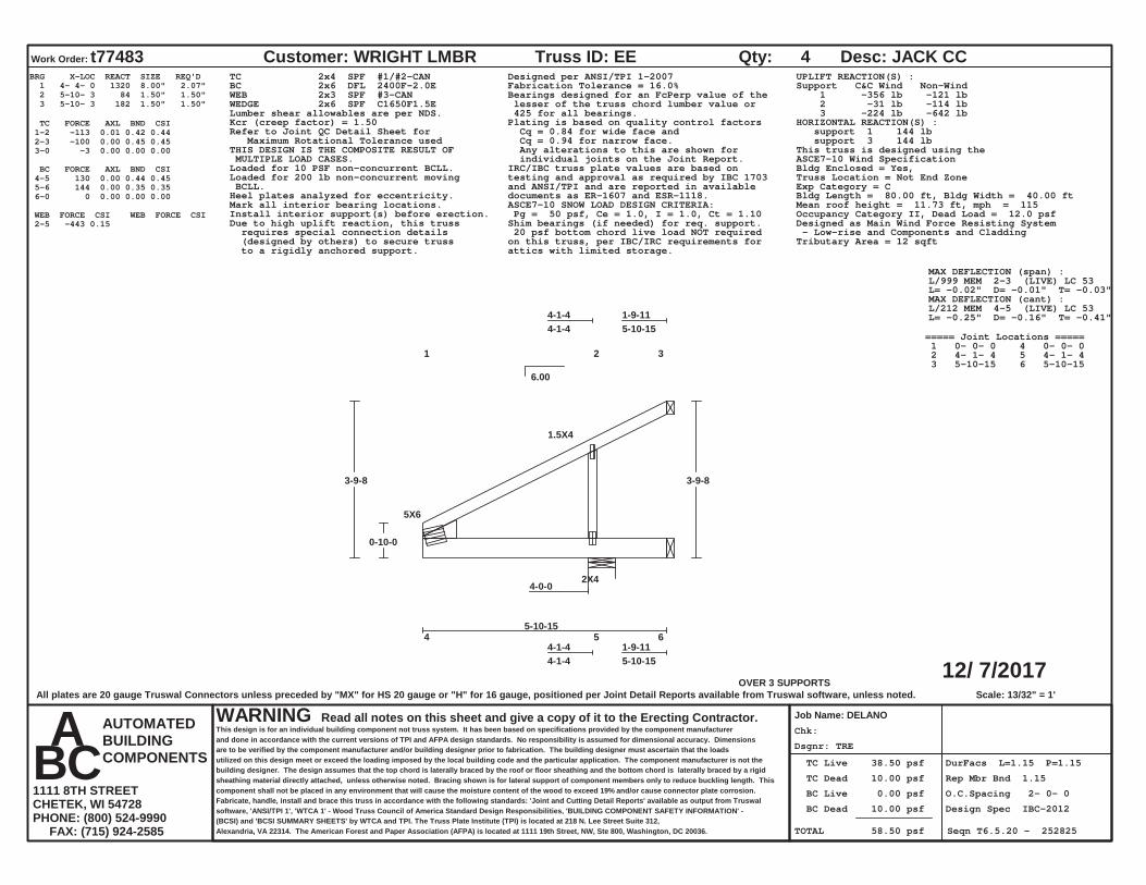
Dsgnr: TRE
Chk:
TC Live 38.50 psf
TC Dead 10.00 psf
BC Live 0.00 psf
BC Dead 10.00 psf
TOTAL 58.50 psf
DurFacs L=1.15 P=1.15
Rep Mbr Bnd 1.15
O.C.Spacing 2- 0- 0
Design Spec IBC-2012
Seqn T6.5.20 - 252825
12/ 7/2017
Work Order: t77483 Customer: WRIGHT LMBR
Job Name: DELANO
Truss ID: EE Qty: 4 Desc: JACK CC
WARNING Read all notes on this sheet and give a copy of it to the Erecting Contractor.This design is for an individual building component not truss system. It has been based on specifications provided by the component manufacturerand done in accordance with the current versions of TPI and AFPA design standards. No responsibility is assumed for dimensional accuracy. Dimensionsare to be verified by the component manufacturer and/or building designer prior to fabrication. The building designer must ascertain that the loadsutilized on this design meet or exceed the loading imposed by the local building code and the particular application. The component manufacturer is not thebuilding designer. The design assumes that the top chord is laterally braced by the roof or floor sheathing and the bottom chord is laterally braced by a rigidsheathing material directly attached, unless otherwise noted. Bracing shown is for lateral support of component members only to reduce buckling length. Thiscomponent shall not be placed in any environment that will cause the moisture content of the wood to exceed 19% and/or cause connector plate corrosion.Fabricate, handle, install and brace this truss in accordance with the following standards: 'Joint and Cutting Detail Reports' available as output from Truswalsoftware, 'ANSI/TPI 1', 'WTCA 1' - Wood Truss Council of America Standard Design Responsibilities, 'BUILDING COMPONENT SAFETY INFORMATION' -(BCSI) and 'BCSI SUMMARY SHEETS' by WTCA and TPI. The Truss Plate Institute (TPI) is located at 218 N. Lee Street Suite 312,Alexandria, VA 22314. The American Forest and Paper Association (AFPA) is located at 1111 19th Street, NW, Ste 800, Washington, DC 20036.
AUTOMATEDBUILDINGCOMPONENTS
A B C 1111 8TH STREETCHETEK, WI 54728PHONE: (800) 524-9990 FAX: (715) 924-2585
6.00
OVER 3 SUPPORTSScale: 13/32" = 1'
1 2 3
4-1-44-1-4
1-9-115-10-15
4 5 6 4-1-44-1-4
1-9-115-10-15
5X6
1.5X4
2X44-0-0
5-10-15
0-10-0
3-9-8 3-9-8
BRG X-LOC REACT SIZE REQ'D 1 4- 4- 0 1320 8.00" 2.07" 2 5-10- 3 84 1.50" 1.50" 3 5-10- 3 182 1.50" 1.50"
TC FORCE AXL BND CSI 1-2 -113 0.01 0.42 0.44 2-3 -100 0.00 0.45 0.45 3-0 -3 0.00 0.00 0.00
BC FORCE AXL BND CSI 4-5 130 0.00 0.44 0.45 5-6 144 0.00 0.35 0.35 6-0 0 0.00 0.00 0.00
WEB FORCE CSI WEB FORCE CSI 2-5 -443 0.15
TC 2x4 SPF #1/#2-CANBC 2x6 DFL 2400F-2.0EWEB 2x3 SPF #3-CANWEDGE 2x6 SPF C1650F1.5ELumber shear allowables are per NDS.
Designed per ANSI/TPI 1-2007Fabrication Tolerance = 16.0%Bearings designed for an FcPerp value of the lesser of the truss chord lumber value or 425 for all bearings.Plating is based on quality control factors Cq = 0.84 for wide face and Cq = 0.94 for narrow face. Any alterations to this are shown for individual joints on the Joint Report.
Kcr (creep factor) = 1.50Refer to Joint QC Detail Sheet for Maximum Rotational Tolerance usedTHIS DESIGN IS THE COMPOSITE RESULT OF MULTIPLE LOAD CASES.
IRC/IBC truss plate values are based ontesting and approval as required by IBC 1703and ANSI/TPI and are reported in availabledocuments as ER-1607 and ESR-1118.
Loaded for 10 PSF non-concurrent BCLL.Loaded for 200 lb non-concurrent moving BCLL.Heel plates analyzed for eccentricity.
ASCE7-10 SNOW LOAD DESIGN CRITERIA: Pg = 50 psf, Ce = 1.0, I = 1.0, Ct = 1.10
Mark all interior bearing locations.Install interior support(s) before erection.
Shim bearings (if needed) for req. support.
UPLIFT REACTION(S) :Support C&C Wind Non-Wind 1 -356 lb -121 lb 2 -31 lb -114 lb 3 -224 lb -642 lb
Due to high uplift reaction, this truss requires special connection details (designed by others) to secure truss to a rigidly anchored support.
HORIZONTAL REACTION(S) : support 1 144 lb support 3 144 lbThis truss is designed using theASCE7-10 Wind SpecificationBldg Enclosed = Yes,Truss Location = Not End ZoneExp Category = CBldg Length = 80.00 ft, Bldg Width = 40.00 ftMean roof height = 11.73 ft, mph = 115Occupancy Category II, Dead Load = 12.0 psfDesigned as Main Wind Force Resisting System - Low-rise and Components and CladdingTributary Area = 12 sqft
20 psf bottom chord live load NOT requiredon this truss, per IBC/IRC requirements forattics with limited storage.
MAX DEFLECTION (span) :L/999 MEM 2-3 (LIVE) LC 53L= -0.02" D= -0.01" T= -0.03"MAX DEFLECTION (cant) :L/212 MEM 4-5 (LIVE) LC 53L= -0.25" D= -0.16" T= -0.41"
===== Joint Locations ===== 1 0- 0- 0 4 0- 0- 0 2 4- 1- 4 5 4- 1- 4 3 5-10-15 6 5-10-15
All plates are 20 gauge Truswal Connectors unless preceded by "MX" for HS 20 gauge or "H" for 16 gauge, positioned per Joint Detail Reports available from Truswal software, unless noted.

Dsgnr: TRE
Chk:
TC Live 38.50 psf
TC Dead 10.00 psf
BC Live 0.00 psf
BC Dead 10.00 psf
TOTAL 58.50 psf
DurFacs L=1.15 P=1.15
Rep Mbr Bnd 1.00
O.C.Spacing 2- 0- 0
Design Spec IBC-2012
Seqn T6.5.20 - 252826
12/ 7/2017
Work Order: t77483 Customer: WRIGHT LMBR
Job Name: DELANO
Truss ID: ER Qty: 2 Desc: HIP MASTER
WARNING Read all notes on this sheet and give a copy of it to the Erecting Contractor.This design is for an individual building component not truss system. It has been based on specifications provided by the component manufacturerand done in accordance with the current versions of TPI and AFPA design standards. No responsibility is assumed for dimensional accuracy. Dimensionsare to be verified by the component manufacturer and/or building designer prior to fabrication. The building designer must ascertain that the loadsutilized on this design meet or exceed the loading imposed by the local building code and the particular application. The component manufacturer is not thebuilding designer. The design assumes that the top chord is laterally braced by the roof or floor sheathing and the bottom chord is laterally braced by a rigidsheathing material directly attached, unless otherwise noted. Bracing shown is for lateral support of component members only to reduce buckling length. Thiscomponent shall not be placed in any environment that will cause the moisture content of the wood to exceed 19% and/or cause connector plate corrosion.Fabricate, handle, install and brace this truss in accordance with the following standards: 'Joint and Cutting Detail Reports' available as output from Truswalsoftware, 'ANSI/TPI 1', 'WTCA 1' - Wood Truss Council of America Standard Design Responsibilities, 'BUILDING COMPONENT SAFETY INFORMATION' -(BCSI) and 'BCSI SUMMARY SHEETS' by WTCA and TPI. The Truss Plate Institute (TPI) is located at 218 N. Lee Street Suite 312,Alexandria, VA 22314. The American Forest and Paper Association (AFPA) is located at 1111 19th Street, NW, Ste 800, Washington, DC 20036.
AUTOMATEDBUILDINGCOMPONENTS
A B C 1111 8TH STREETCHETEK, WI 54728PHONE: (800) 524-9990 FAX: (715) 924-2585
4.24
Scale: 7/32" = 1'
1 2 3 4
5-8-145-8-14
5-6-311-3-1
5-6-316-9-3
5 6 7 8 5-8-145-8-14
5-6-311-3-1
5-6-316-9-3
3X8
6X6
5X6
1.5X4
2X44X8 8X8
5-7-2
16-9-3
0-10-0
6-9-2 6-9-2
468# 0-0-12
8-5-1
8-5-3
11-3-0
11-3-2
14-0-15
14-1-1
8-5-1
8-5-3 11-3-011-3-2 14-0-1514-1-1
BRG X-LOC REACT SIZE REQ'D 1 6- 0-13 2879 11.31" 4.52" 2 16- 8- 7 1313 HGR 2.06"BRG HANGER/CLIP NOTE 2 Hanger TBE**HANGER(S) TO BE ENGINEEREDSupport Connection(s)/Hanger(s) are not designed for horizontal loads.
TC FORCE AXL BND CSI 1-2 2019 0.18 0.49 0.67 2-3 1491 0.15 0.38 0.53 3-4 -175 0.01 0.56 0.57
BC FORCE AXL BND CSI 5-6 -1774 0.01 0.32 0.33 6-7 -1866 0.02 0.82 0.84 7-8 -1330 0.00 0.30 0.31
WEB FORCE CSI WEB FORCE CSI 2-6 -2435 0.59 2-7 2351 0.58 3-7 -1467 0.59
3-8 1715 0.76 4-8 -411 0.32
TC 2x6 SPF C1650F1.5EBC 2x6 SPF C1650F1.5EWEB 2x4 SPF #3-CAN 2x4 SPF #1/#2-CAN 2-7Lumber shear allowables are per NDS.
Web bracing required at each location shown. Refer to BCSI for proper required lateral restraint. For alternative web bracing, see ITWBCG's standard details.Designed per ANSI/TPI 1-2007Fabrication Tolerance = 16.0%Bearings designed for an FcPerp value of the
lesser of the truss chord lumber value or 425 for all bearings.
Plating is based on quality control factors Cq = 0.84 for wide face and Cq = 0.94 for narrow face. Any alterations to this are shown for individual joints on the Joint Report.
Kcr (creep factor) = 1.50Refer to Joint QC Detail Sheet for Maximum Rotational Tolerance used
THIS DESIGN IS THE COMPOSITE RESULT OF MULTIPLE LOAD CASES.
IRC/IBC truss plate values are based ontesting and approval as required by IBC 1703and ANSI/TPI and are reported in availabledocuments as ER-1607 and ESR-1118.
Loaded for 10 PSF non-concurrent BCLL.Loaded for 200 lb non-concurrent moving BCLL.ASCE7-10 SNOW LOAD DESIGN CRITERIA:
Pg = 50 psf, Ce = 1.0, I = 1.0, Ct = 1.10 Permanent bracing is required (by others) to prevent rotation/toppling. See BCSI and ANSI/TPI 1.
End verticals are designed for axial loadsonly unless noted otherwise.Extensions above or below the truss profile(if any) have been designed for loadsindicated only. Horizontal loads applied atthe end of the extensions have not beenconsidered unless shown. A drop-leg to anotherwise unsupported wall may create ahinge effect that requires additional designconsideration (by others).
Hanger nail points that protrude through the back face of the girder shall be clinched or covered for safety.
Required bearing widths and bearing areasapply when truss not supported in a hanger.UPLIFT REACTION(S) :Support Main Wind Non-Wind 1 -144 lb -681 lb 2 -409 lb -976 lbDue to high uplift reaction, this truss requires special connection details (designed by others) to secure truss to a rigidly anchored support.HORIZONTAL REACTION(S) :
support 1 107 lb support 2 114 lb
This truss is designed using theASCE7-10 Wind SpecificationBldg Enclosed = Yes,Truss Location = Not End ZoneExp Category = CBldg Length = 80.00 ft, Bldg Width = 40.00 ftMean roof height = 13.14 ft, mph = 115Occupancy Category II, Dead Load = 12.0 psfDesigned as Main Wind Force Resisting System - Low-rise and Components and CladdingTributary Area = 15 sqft
20 psf bottom chord live load NOT requiredon this truss, per IBC/IRC requirements forattics with limited storage.----------LOAD CASE #1 DESIGN LOADS ---------------- Dir L.Plf L.Loc R.Plf R.Loc LL/TLTC Vert 97.00 0- 0- 0 97.00 7- 5- 1 0.79TC Vert 48.50 7- 5- 1 48.50 9- 5- 3 0.79TC Vert 97.00 9- 5- 3 97.00 10- 3- 0 0.79TC Vert 48.50 10- 3- 0 48.50 12- 3- 2 0.79TC Vert 97.00 12- 3- 2 97.00 13- 0-15 0.79TC Vert 48.50 13- 0-15 48.50 15- 1- 1 0.79TC Vert 97.00 15- 1- 1 97.00 16- 9- 3 0.79BC Vert 20.00 0- 0- 0 20.00 7- 5- 1 0.00BC Vert 10.00 7- 5- 1 10.00 9- 5- 3 0.00BC Vert 20.00 9- 5- 3 20.00 10- 3- 0 0.00BC Vert 10.00 10- 3- 0 10.00 12- 3- 2 0.00BC Vert 20.00 12- 3- 2 20.00 13- 0-15 0.00BC Vert 10.00 13- 0-15 10.00 15- 1- 1 0.00BC Vert 20.00 15- 1- 1 20.00 16- 9- 3 0.00...Type... lbs X.Loc LL/TL FastenerTC Vert 468.0 0- 0-12 0.70------------ CRITICAL POINT LOADS ------------------ Type X.Loc Max/Dur Min/DurTC Vert 8- 5- 1 84/1.60 -114/1.15TC Vert 8- 5- 3 84/1.60 -114/1.15TC Vert 11- 3- 0 184/1.60 -90/1.15TC Vert 11- 3- 2 184/1.60 -90/1.15TC Vert 14- 0-15 232/1.15 -97/1.60TC Vert 14- 1- 1 232/1.15 -97/1.60BC Vert 8- 5- 1 135/1.60 -579/1.15BC Vert 8- 5- 3 135/1.60 -579/1.15BC Vert 11- 3- 0 81/1.60 -148/1.15BC Vert 11- 3- 2 81/1.60 -148/1.15BC Vert 14- 0-15 95/1.60 -60/1.15BC Vert 14- 1- 1 95/1.60 -60/1.15
MAX DEFLECTION (span) :L/999 MEM 3-4 (LIVE) LC 32L= -0.10" D= -0.03" T= -0.13"MAX DEFLECTION (cant) :L/317 MEM 5-6 (LIVE) LC 35L= -0.23" D= -0.16" T= -0.39"
===== Joint Locations ===== 1 0- 0- 0 5 0- 0- 0 2 5- 8-14 6 5- 8-14 3 11- 3- 1 7 11- 3- 1 4 16- 9- 3 8 16- 9- 3
All plates are 20 gauge Truswal Connectors unless preceded by "MX" for HS 20 gauge or "H" for 16 gauge, positioned per Joint Detail Reports available from Truswal software, unless noted.
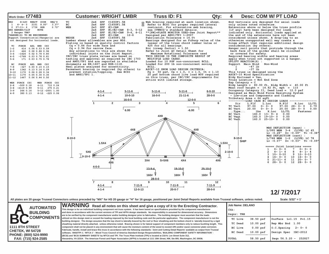
Dsgnr: TRE
Chk:
TC Live 38.50 psf
TC Dead 10.00 psf
BC Live 0.00 psf
BC Dead 10.00 psf
TOTAL 58.50 psf
DurFacs L=1.15 P=1.15
Rep Mbr Bnd 1.00
O.C.Spacing 2- 0- 0
Design Spec IBC-2012
Seqn T6.5.20 - 252827
12/ 7/2017
Work Order: t77483 Customer: WRIGHT LMBR
Job Name: DELANO
Truss ID: F1 Qty: 4 Desc: COM W/ PT LOAD
WARNING Read all notes on this sheet and give a copy of it to the Erecting Contractor.This design is for an individual building component not truss system. It has been based on specifications provided by the component manufacturerand done in accordance with the current versions of TPI and AFPA design standards. No responsibility is assumed for dimensional accuracy. Dimensionsare to be verified by the component manufacturer and/or building designer prior to fabrication. The building designer must ascertain that the loadsutilized on this design meet or exceed the loading imposed by the local building code and the particular application. The component manufacturer is not thebuilding designer. The design assumes that the top chord is laterally braced by the roof or floor sheathing and the bottom chord is laterally braced by a rigidsheathing material directly attached, unless otherwise noted. Bracing shown is for lateral support of component members only to reduce buckling length. Thiscomponent shall not be placed in any environment that will cause the moisture content of the wood to exceed 19% and/or cause connector plate corrosion.Fabricate, handle, install and brace this truss in accordance with the following standards: 'Joint and Cutting Detail Reports' available as output from Truswalsoftware, 'ANSI/TPI 1', 'WTCA 1' - Wood Truss Council of America Standard Design Responsibilities, 'BUILDING COMPONENT SAFETY INFORMATION' -(BCSI) and 'BCSI SUMMARY SHEETS' by WTCA and TPI. The Truss Plate Institute (TPI) is located at 218 N. Lee Street Suite 312,Alexandria, VA 22314. The American Forest and Paper Association (AFPA) is located at 1111 19th Street, NW, Ste 800, Washington, DC 20036.
AUTOMATEDBUILDINGCOMPONENTS
A B C 1111 8TH STREETCHETEK, WI 54728PHONE: (800) 524-9990 FAX: (715) 924-2585
6.00 -6.00
Scale: 5/32" = 1'
1 2 3 4 5 6
4-1-44-1-4
5-11-610-0-10
5-11-616-0-0
5-11-621-11-6
6-0-1028-0-0
7 8 9 10 11 124-1-44-1-4
7-11-912-0-13
7-11-920-0-7
7-11-928-0-0
5X6
1.5X4
4X8
4X8
4X8
1.5X4
4X63X4 S=5X6 4X4 4X6
4-0-0
28-0-0
0-10-0
8-10-0
2-10-0
8-10-0
16-0-0 12-0-0
160# 13-9-4
160# 19-10-0
160# 25-10-0
SHIP
BRG X-LOC REACT SIZE REQ'D 1 4- 4- 0 2151 8.00" 3.37" 2 27-11- 4 1736 HGR 2.72"BRG HANGER/CLIP NOTE 2 Hanger TBE**HANGER(S) TO BE ENGINEEREDSupport Connection(s)/Hanger(s) are not designed for horizontal loads.
TC FORCE AXL BND CSI 1-2 414 0.06 0.53 0.59 2-3 466 0.08 0.88 0.96 3-4 -1626 0.02 0.78 0.80 4-5 -1768 0.03 0.78 0.81 5-6 171 0.03 0.75 0.78
BC FORCE AXL BND CSI 7-8 -327 0.00 0.15 0.15 8-9 1342 0.13 0.16 0.29 9-10 1170 0.06 0.28 0.3410-11 1170 0.05 0.30 0.3511-12 1467 0.06 0.44 0.50
WEB FORCE CSI WEB FORCE CSI 2-8 -509 0.18 3-8 -2119 0.99 3-9 266 0.16 4-9 380 0.13
4-11 712 0.24 5-11 275 0.21 5-12 -2001 1.00 6-12 -225 0.06
TC 2x4 SPF C1650F1.5EBC 2x6 SPF C1650F1.5EWEB 2x3 SPF #3-CAN 2x4 SPF #1/#2-CAN 8-3, 5-12 2x3 SPF #1/#2-CAN 9-4, 4-11 2x4 SPF #3-CAN 12-6WEDGE 2x6 SPF C1650F1.5ELumber shear allowables are per NDS.
Web bracing required at each location shown. Refer to BCSI for proper required lateral restraint. For alternative web bracing, see ITWBCG's standard details.**[PM]=PLATE MONITOR USED-See Joint Report**Designed per ANSI/TPI 1-2007Fabrication Tolerance = 16.0%Bearings designed for an FcPerp value of the lesser of the truss chord lumber value or 425 for all bearings.
Plating is based on quality control factors Cq = 0.84 for wide face and Cq = 0.94 for narrow face. Any alterations to this are shown for individual joints on the Joint Report.
Kcr (creep factor) = 1.50Refer to Joint QC Detail Sheet for Maximum Rotational Tolerance usedTHIS DESIGN IS THE COMPOSITE RESULT OF MULTIPLE LOAD CASES.
IRC/IBC truss plate values are based ontesting and approval as required by IBC 1703and ANSI/TPI and are reported in availabledocuments as ER-1607 and ESR-1118.
Loaded for 10 PSF non-concurrent BCLL.Loaded for 200 lb non-concurrent moving BCLL.Heel plates analyzed for eccentricity.ASCE7-10 SNOW LOAD DESIGN CRITERIA: Pg = 50 psf, Ce = 1.0, I = 1.0, Ct = 1.10
Permanent bracing is required (by others) to prevent rotation/toppling. See BCSI and ANSI/TPI 1.
End verticals are designed for axial loadsonly unless noted otherwise.Extensions above or below the truss profile(if any) have been designed for loadsindicated only. Horizontal loads applied atthe end of the extensions have not beenconsidered unless shown. A drop-leg to anotherwise unsupported wall may create ahinge effect that requires additional designconsideration (by others).Hanger nail points that protrude through the back face of the girder shall be clinched or covered for safety.Required bearing widths and bearing areasapply when truss not supported in a hanger.UPLIFT REACTION(S) :Support Main Wind Non-Wind 1 -47 lb 2 -37 lbThis truss is designed using theASCE7-10 Wind SpecificationBldg Enclosed = Yes,Truss Location = Not End ZoneExp Category = CBldg Length = 80.00 ft, Bldg Width = 40.00 ftMean roof height = 14.42 ft, mph = 115Occupancy Category II, Dead Load = 12.0 psfDesigned as Main Wind Force Resisting System - Low-rise and Components and CladdingTributary Area = 64 sqft
20 psf bottom chord live load NOT requiredon this truss, per IBC/IRC requirements forattics with limited storage.
----------LOAD CASE #1 DESIGN LOADS ---------------- Dir L.Plf L.Loc R.Plf R.Loc LL/TLTC Vert 97.00 0- 0- 0 97.00 28- 0- 0 0.79BC Vert 20.00 0- 0- 0 20.00 28- 0- 0 0.00...Type... lbs X.Loc LL/TL FastenerBC Vert 160.0 13- 9- 4 0.00BC Vert 160.0 19-10- 0 0.00BC Vert 160.0 25-10- 0 0.00
MAX DEFLECTION (span) :L/995 MEM 3-4 (LIVE) LC 45L= -0.28" D= -0.09" T= -0.38"MAX DEFLECTION (cant) :L/768 MEM 1-2 (LIVE) LC 78L= -0.07" D= -0.03" T= -0.09"
===== Joint Locations ===== 1 0- 0- 0 7 0- 0- 0 2 4- 1- 4 8 4- 1- 4 3 10- 0-10 9 12- 0-13 4 16- 0- 0 10 16- 0- 0 5 21-11- 6 11 20- 0- 7 6 28- 0- 0 12 28- 0- 0
All plates are 20 gauge Truswal Connectors unless preceded by "MX" for HS 20 gauge or "H" for 16 gauge, positioned per Joint Detail Reports available from Truswal software, unless noted.

Dsgnr: TRE
Chk:
TC Live 38.50 psf
TC Dead 10.00 psf
BC Live 0.00 psf
BC Dead 10.00 psf
TOTAL 58.50 psf
DurFacs L=1.15 P=1.15
Rep Mbr Bnd 1.00
O.C.Spacing 2- 0- 0
Design Spec IBC-2012
Seqn T6.5.20 - 252828
12/ 7/2017
Work Order: t77483 Customer: WRIGHT LMBR
Job Name: DELANO
Truss ID: F2 Qty: 3 Desc:
WARNING Read all notes on this sheet and give a copy of it to the Erecting Contractor.This design is for an individual building component not truss system. It has been based on specifications provided by the component manufacturerand done in accordance with the current versions of TPI and AFPA design standards. No responsibility is assumed for dimensional accuracy. Dimensionsare to be verified by the component manufacturer and/or building designer prior to fabrication. The building designer must ascertain that the loadsutilized on this design meet or exceed the loading imposed by the local building code and the particular application. The component manufacturer is not thebuilding designer. The design assumes that the top chord is laterally braced by the roof or floor sheathing and the bottom chord is laterally braced by a rigidsheathing material directly attached, unless otherwise noted. Bracing shown is for lateral support of component members only to reduce buckling length. Thiscomponent shall not be placed in any environment that will cause the moisture content of the wood to exceed 19% and/or cause connector plate corrosion.Fabricate, handle, install and brace this truss in accordance with the following standards: 'Joint and Cutting Detail Reports' available as output from Truswalsoftware, 'ANSI/TPI 1', 'WTCA 1' - Wood Truss Council of America Standard Design Responsibilities, 'BUILDING COMPONENT SAFETY INFORMATION' -(BCSI) and 'BCSI SUMMARY SHEETS' by WTCA and TPI. The Truss Plate Institute (TPI) is located at 218 N. Lee Street Suite 312,Alexandria, VA 22314. The American Forest and Paper Association (AFPA) is located at 1111 19th Street, NW, Ste 800, Washington, DC 20036.
AUTOMATEDBUILDINGCOMPONENTS
A B C 1111 8TH STREETCHETEK, WI 54728PHONE: (800) 524-9990 FAX: (715) 924-2585
6.00 -6.00
Scale: 5/32" = 1'
1 2 3 4 5 6
4-1-44-1-4
5-11-610-0-10
5-11-616-0-0
5-11-621-11-6
6-0-1028-0-0
7 8 9 10 11 124-1-44-1-4
7-11-912-0-13
7-11-920-0-7
7-11-928-0-0
5X6
1.5X4
4X8
4X10
4X8
1.5X4
5X63X4 S=5X6 8X8 5X6
4-0-0
28-0-0
0-10-0
8-10-0
2-10-0
8-10-0
16-0-0 12-0-0
320# 13-9-4
320# 19-10-0
320# 25-10-0
SHIP
BRG X-LOC REACT SIZE REQ'D 1 4- 4- 0 2315 8.00" 3.63" 2 27-11- 4 2052 HGR 3.22"BRG HANGER/CLIP NOTE 2 Hanger TBE**HANGER(S) TO BE ENGINEEREDSupport Connection(s)/Hanger(s) are not designed for horizontal loads.
TC FORCE AXL BND CSI 1-2 418 0.06 0.53 0.59 2-3 470 0.08 0.88 0.96 3-4 -1856 0.04 0.78 0.82 4-5 -2061 0.04 0.78 0.82 5-6 171 0.03 0.74 0.77
BC FORCE AXL BND CSI 7-8 -331 0.00 0.14 0.14 8-9 1519 0.08 0.27 0.35 9-10 1348 0.07 0.35 0.4210-11 1348 0.09 0.38 0.4711-12 1696 0.08 0.59 0.68
WEB FORCE CSI WEB FORCE CSI 2-8 -511 0.18 3-8 -2370 1.00 3-9 343 0.21 4-9 446 0.15
4-11 905 0.31 5-11 366 0.17 5-12 -2313 0.98 6-12 -226 0.06
TC 2x4 SPF C1650F1.5EBC 2x6 SPF C1650F1.5EWEB 2x3 SPF #3-CAN 2x4 SPF #1/#2-CAN 8-3, 5-12 2x3 SPF #1/#2-CAN 9-4, 4-11 2x4 SPF #3-CAN 12-6WEDGE 2x6 SPF C1650F1.5ELumber shear allowables are per NDS.
Web bracing required at each location shown. Refer to BCSI for proper required lateral restraint. For alternative web bracing, see ITWBCG's standard details.**[PM]=PLATE MONITOR USED-See Joint Report**Designed per ANSI/TPI 1-2007Fabrication Tolerance = 16.0%Bearings designed for an FcPerp value of the lesser of the truss chord lumber value or 425 for all bearings.
Plating is based on quality control factors Cq = 0.84 for wide face and Cq = 0.94 for narrow face. Any alterations to this are shown for individual joints on the Joint Report.
Kcr (creep factor) = 1.50Refer to Joint QC Detail Sheet for Maximum Rotational Tolerance usedTHIS DESIGN IS THE COMPOSITE RESULT OF MULTIPLE LOAD CASES.
IRC/IBC truss plate values are based ontesting and approval as required by IBC 1703and ANSI/TPI and are reported in availabledocuments as ER-1607 and ESR-1118.
Loaded for 10 PSF non-concurrent BCLL.Loaded for 200 lb non-concurrent moving BCLL.Heel plates analyzed for eccentricity.ASCE7-10 SNOW LOAD DESIGN CRITERIA: Pg = 50 psf, Ce = 1.0, I = 1.0, Ct = 1.10
Permanent bracing is required (by others) to prevent rotation/toppling. See BCSI and ANSI/TPI 1.
End verticals are designed for axial loadsonly unless noted otherwise.Extensions above or below the truss profile(if any) have been designed for loadsindicated only. Horizontal loads applied atthe end of the extensions have not beenconsidered unless shown. A drop-leg to anotherwise unsupported wall may create ahinge effect that requires additional designconsideration (by others).Hanger nail points that protrude through the back face of the girder shall be clinched or covered for safety.Required bearing widths and bearing areasapply when truss not supported in a hanger.UPLIFT REACTION(S) :Support Main Wind Non-Wind 1 -50 lb 2 -44 lbThis truss is designed using theASCE7-10 Wind SpecificationBldg Enclosed = Yes,Truss Location = Not End ZoneExp Category = CBldg Length = 80.00 ft, Bldg Width = 40.00 ftMean roof height = 14.42 ft, mph = 115Occupancy Category II, Dead Load = 12.0 psfDesigned as Main Wind Force Resisting System - Low-rise and Components and CladdingTributary Area = 72 sqft
20 psf bottom chord live load NOT requiredon this truss, per IBC/IRC requirements forattics with limited storage.
----------LOAD CASE #1 DESIGN LOADS ---------------- Dir L.Plf L.Loc R.Plf R.Loc LL/TLTC Vert 97.00 0- 0- 0 97.00 28- 0- 0 0.79BC Vert 20.00 0- 0- 0 20.00 28- 0- 0 0.00...Type... lbs X.Loc LL/TL FastenerBC Vert 320.0 13- 9- 4 0.00BC Vert 320.0 19-10- 0 0.00BC Vert 320.0 25-10- 0 0.00
MAX DEFLECTION (span) :L/995 MEM 3-4 (LIVE) LC 45L= -0.28" D= -0.11" T= -0.40"MAX DEFLECTION (cant) :L/772 MEM 1-2 (LIVE) LC 78L= -0.07" D= -0.03" T= -0.10"
===== Joint Locations ===== 1 0- 0- 0 7 0- 0- 0 2 4- 1- 4 8 4- 1- 4 3 10- 0-10 9 12- 0-13 4 16- 0- 0 10 16- 0- 0 5 21-11- 6 11 20- 0- 7 6 28- 0- 0 12 28- 0- 0
All plates are 20 gauge Truswal Connectors unless preceded by "MX" for HS 20 gauge or "H" for 16 gauge, positioned per Joint Detail Reports available from Truswal software, unless noted.
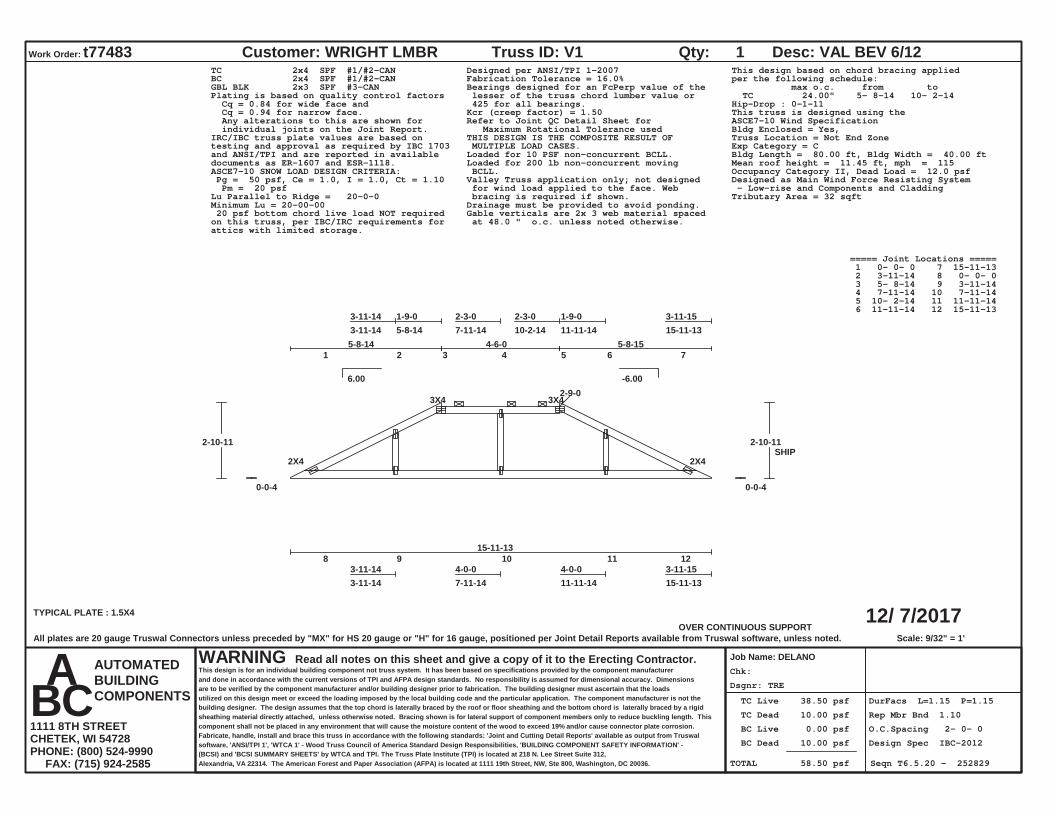
Dsgnr: TRE
Chk:
TC Live 38.50 psf
TC Dead 10.00 psf
BC Live 0.00 psf
BC Dead 10.00 psf
TOTAL 58.50 psf
DurFacs L=1.15 P=1.15
Rep Mbr Bnd 1.10
O.C.Spacing 2- 0- 0
Design Spec IBC-2012
Seqn T6.5.20 - 252829
12/ 7/2017
Work Order: t77483 Customer: WRIGHT LMBR
Job Name: DELANO
Truss ID: V1 Qty: 1 Desc: VAL BEV 6/12
WARNING Read all notes on this sheet and give a copy of it to the Erecting Contractor.This design is for an individual building component not truss system. It has been based on specifications provided by the component manufacturerand done in accordance with the current versions of TPI and AFPA design standards. No responsibility is assumed for dimensional accuracy. Dimensionsare to be verified by the component manufacturer and/or building designer prior to fabrication. The building designer must ascertain that the loadsutilized on this design meet or exceed the loading imposed by the local building code and the particular application. The component manufacturer is not thebuilding designer. The design assumes that the top chord is laterally braced by the roof or floor sheathing and the bottom chord is laterally braced by a rigidsheathing material directly attached, unless otherwise noted. Bracing shown is for lateral support of component members only to reduce buckling length. Thiscomponent shall not be placed in any environment that will cause the moisture content of the wood to exceed 19% and/or cause connector plate corrosion.Fabricate, handle, install and brace this truss in accordance with the following standards: 'Joint and Cutting Detail Reports' available as output from Truswalsoftware, 'ANSI/TPI 1', 'WTCA 1' - Wood Truss Council of America Standard Design Responsibilities, 'BUILDING COMPONENT SAFETY INFORMATION' -(BCSI) and 'BCSI SUMMARY SHEETS' by WTCA and TPI. The Truss Plate Institute (TPI) is located at 218 N. Lee Street Suite 312,Alexandria, VA 22314. The American Forest and Paper Association (AFPA) is located at 1111 19th Street, NW, Ste 800, Washington, DC 20036.
AUTOMATEDBUILDINGCOMPONENTS
A B C 1111 8TH STREETCHETEK, WI 54728PHONE: (800) 524-9990 FAX: (715) 924-2585
6.00 -6.00
OVER CONTINUOUS SUPPORTScale: 9/32" = 1'
1 2 3 4 5 6 7
3-11-143-11-14
1-9-05-8-14
2-3-07-11-14
2-3-010-2-14
1-9-011-11-14
3-11-1515-11-13
8 9 10 11 123-11-143-11-14
4-0-07-11-14
4-0-011-11-14
3-11-1515-11-13
TYPICAL PLATE : 1.5X4
2X4
3X4 3X4
2X4
15-11-13
0-0-4
2-10-11
0-0-4
2-10-11
5-8-14 4-6-0 5-8-15
2-9-0
SHIP
TC 2x4 SPF #1/#2-CANBC 2x4 SPF #1/#2-CANGBL BLK 2x3 SPF #3-CAN
Designed per ANSI/TPI 1-2007Fabrication Tolerance = 16.0%Bearings designed for an FcPerp value of the lesser of the truss chord lumber value or 425 for all bearings.
Plating is based on quality control factors Cq = 0.84 for wide face and Cq = 0.94 for narrow face. Any alterations to this are shown for individual joints on the Joint Report.
Kcr (creep factor) = 1.50Refer to Joint QC Detail Sheet for Maximum Rotational Tolerance usedTHIS DESIGN IS THE COMPOSITE RESULT OF MULTIPLE LOAD CASES.
IRC/IBC truss plate values are based ontesting and approval as required by IBC 1703and ANSI/TPI and are reported in availabledocuments as ER-1607 and ESR-1118.
Loaded for 10 PSF non-concurrent BCLL.Loaded for 200 lb non-concurrent moving BCLL.ASCE7-10 SNOW LOAD DESIGN CRITERIA:
Pg = 50 psf, Ce = 1.0, I = 1.0, Ct = 1.10 Pm = 20 psfLu Parallel to Ridge = 20-0-0Minimum Lu = 20-00-00
Valley Truss application only; not designed for wind load applied to the face. Web bracing is required if shown.Drainage must be provided to avoid ponding.Gable verticals are 2x 3 web material spaced at 48.0 " o.c. unless noted otherwise.
This design based on chord bracing appliedper the following schedule: max o.c. from to TC 24.00" 5- 8-14 10- 2-14Hip-Drop : 0-1-11This truss is designed using theASCE7-10 Wind SpecificationBldg Enclosed = Yes,Truss Location = Not End ZoneExp Category = CBldg Length = 80.00 ft, Bldg Width = 40.00 ftMean roof height = 11.45 ft, mph = 115Occupancy Category II, Dead Load = 12.0 psfDesigned as Main Wind Force Resisting System - Low-rise and Components and CladdingTributary Area = 32 sqft
20 psf bottom chord live load NOT requiredon this truss, per IBC/IRC requirements forattics with limited storage.
===== Joint Locations ===== 1 0- 0- 0 7 15-11-13 2 3-11-14 8 0- 0- 0 3 5- 8-14 9 3-11-14 4 7-11-14 10 7-11-14 5 10- 2-14 11 11-11-14 6 11-11-14 12 15-11-13
All plates are 20 gauge Truswal Connectors unless preceded by "MX" for HS 20 gauge or "H" for 16 gauge, positioned per Joint Detail Reports available from Truswal software, unless noted.
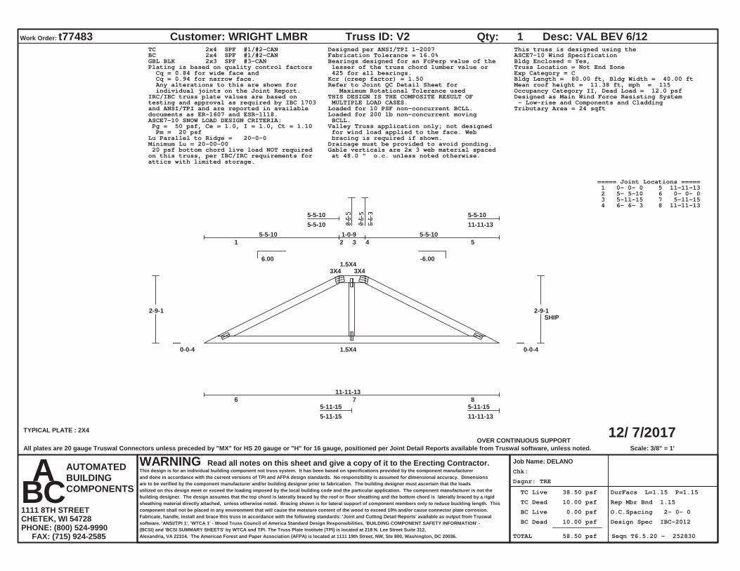
Dsgnr: TRE
Chk:
TC Live 38.50 psf
TC Dead 10.00 psf
BC Live 0.00 psf
BC Dead 10.00 psf
TOTAL 58.50 psf
DurFacs L=1.15 P=1.15
Rep Mbr Bnd 1.15
O.C.Spacing 2- 0- 0
Design Spec IBC-2012
Seqn T6.5.20 - 252830
12/ 7/2017
Work Order: t77483 Customer: WRIGHT LMBR
Job Name: DELANO
Truss ID: V2 Qty: 1 Desc: VAL BEV 6/12
WARNING Read all notes on this sheet and give a copy of it to the Erecting Contractor.This design is for an individual building component not truss system. It has been based on specifications provided by the component manufacturerand done in accordance with the current versions of TPI and AFPA design standards. No responsibility is assumed for dimensional accuracy. Dimensionsare to be verified by the component manufacturer and/or building designer prior to fabrication. The building designer must ascertain that the loadsutilized on this design meet or exceed the loading imposed by the local building code and the particular application. The component manufacturer is not thebuilding designer. The design assumes that the top chord is laterally braced by the roof or floor sheathing and the bottom chord is laterally braced by a rigidsheathing material directly attached, unless otherwise noted. Bracing shown is for lateral support of component members only to reduce buckling length. Thiscomponent shall not be placed in any environment that will cause the moisture content of the wood to exceed 19% and/or cause connector plate corrosion.Fabricate, handle, install and brace this truss in accordance with the following standards: 'Joint and Cutting Detail Reports' available as output from Truswalsoftware, 'ANSI/TPI 1', 'WTCA 1' - Wood Truss Council of America Standard Design Responsibilities, 'BUILDING COMPONENT SAFETY INFORMATION' -(BCSI) and 'BCSI SUMMARY SHEETS' by WTCA and TPI. The Truss Plate Institute (TPI) is located at 218 N. Lee Street Suite 312,Alexandria, VA 22314. The American Forest and Paper Association (AFPA) is located at 1111 19th Street, NW, Ste 800, Washington, DC 20036.
AUTOMATEDBUILDINGCOMPONENTS
A B C 1111 8TH STREETCHETEK, WI 54728PHONE: (800) 524-9990 FAX: (715) 924-2585
6.00 -6.00
OVER CONTINUOUS SUPPORTScale: 3/8" = 1'
1 2 3 4 5
5-5-105-5-10
5-5-1011-11-13
6 7 8 5-11-155-11-15
5-11-1511-11-13
TYPICAL PLATE : 2X4
3X41.5X4
3X4
1.5X4
11-11-13
0-0-4
2-9-1
0-0-4
2-9-1
5-5-10 1-0-9 5-5-10
SHIP
TC 2x4 SPF #1/#2-CANBC 2x4 SPF #1/#2-CANGBL BLK 2x3 SPF #3-CAN
Designed per ANSI/TPI 1-2007Fabrication Tolerance = 16.0%Bearings designed for an FcPerp value of the lesser of the truss chord lumber value or 425 for all bearings.
Plating is based on quality control factors Cq = 0.84 for wide face and Cq = 0.94 for narrow face. Any alterations to this are shown for individual joints on the Joint Report.
Kcr (creep factor) = 1.50Refer to Joint QC Detail Sheet for Maximum Rotational Tolerance usedTHIS DESIGN IS THE COMPOSITE RESULT OF MULTIPLE LOAD CASES.
IRC/IBC truss plate values are based ontesting and approval as required by IBC 1703and ANSI/TPI and are reported in availabledocuments as ER-1607 and ESR-1118.
Loaded for 10 PSF non-concurrent BCLL.Loaded for 200 lb non-concurrent moving BCLL.ASCE7-10 SNOW LOAD DESIGN CRITERIA:
Pg = 50 psf, Ce = 1.0, I = 1.0, Ct = 1.10 Pm = 20 psfLu Parallel to Ridge = 20-0-0Minimum Lu = 20-00-00
Valley Truss application only; not designed for wind load applied to the face. Web bracing is required if shown.Drainage must be provided to avoid ponding.Gable verticals are 2x 3 web material spaced at 48.0 " o.c. unless noted otherwise.
This truss is designed using theASCE7-10 Wind SpecificationBldg Enclosed = Yes,Truss Location = Not End ZoneExp Category = CBldg Length = 80.00 ft, Bldg Width = 40.00 ftMean roof height = 11.38 ft, mph = 115Occupancy Category II, Dead Load = 12.0 psfDesigned as Main Wind Force Resisting System - Low-rise and Components and CladdingTributary Area = 24 sqft
20 psf bottom chord live load NOT requiredon this truss, per IBC/IRC requirements forattics with limited storage.
===== Joint Locations ===== 1 0- 0- 0 5 11-11-13 2 5- 5-10 6 0- 0- 0 3 5-11-15 7 5-11-15 4 6- 6- 3 8 11-11-13
All plates are 20 gauge Truswal Connectors unless preceded by "MX" for HS 20 gauge or "H" for 16 gauge, positioned per Joint Detail Reports available from Truswal software, unless noted.
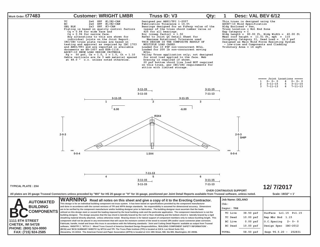
Dsgnr: TRE
Chk:
TC Live 38.50 psf
TC Dead 10.00 psf
BC Live 0.00 psf
BC Dead 10.00 psf
TOTAL 58.50 psf
DurFacs L=1.15 P=1.15
Rep Mbr Bnd 1.15
O.C.Spacing 2- 0- 0
Design Spec IBC-2012
Seqn T6.5.20 - 252831
12/ 7/2017
Work Order: t77483 Customer: WRIGHT LMBR
Job Name: DELANO
Truss ID: V3 Qty: 1 Desc: VAL BEV 6/12
WARNING Read all notes on this sheet and give a copy of it to the Erecting Contractor.This design is for an individual building component not truss system. It has been based on specifications provided by the component manufacturerand done in accordance with the current versions of TPI and AFPA design standards. No responsibility is assumed for dimensional accuracy. Dimensionsare to be verified by the component manufacturer and/or building designer prior to fabrication. The building designer must ascertain that the loadsutilized on this design meet or exceed the loading imposed by the local building code and the particular application. The component manufacturer is not thebuilding designer. The design assumes that the top chord is laterally braced by the roof or floor sheathing and the bottom chord is laterally braced by a rigidsheathing material directly attached, unless otherwise noted. Bracing shown is for lateral support of component members only to reduce buckling length. Thiscomponent shall not be placed in any environment that will cause the moisture content of the wood to exceed 19% and/or cause connector plate corrosion.Fabricate, handle, install and brace this truss in accordance with the following standards: 'Joint and Cutting Detail Reports' available as output from Truswalsoftware, 'ANSI/TPI 1', 'WTCA 1' - Wood Truss Council of America Standard Design Responsibilities, 'BUILDING COMPONENT SAFETY INFORMATION' -(BCSI) and 'BCSI SUMMARY SHEETS' by WTCA and TPI. The Truss Plate Institute (TPI) is located at 218 N. Lee Street Suite 312,Alexandria, VA 22314. The American Forest and Paper Association (AFPA) is located at 1111 19th Street, NW, Ste 800, Washington, DC 20036.
AUTOMATEDBUILDINGCOMPONENTS
A B C 1111 8TH STREETCHETEK, WI 54728PHONE: (800) 524-9990 FAX: (715) 924-2585
6.00 -6.00
OVER CONTINUOUS SUPPORTScale: 19/32" = 1'
1 2 3
3-11-153-11-15
3-11-157-11-13
4 5 6 3-11-153-11-15
3-11-157-11-13TYPICAL PLATE : 2X4
R3X4
1.5X4
7-11-13
0-0-4
2-0-3
0-0-4
2-0-3
3-11-15 3-11-15
SHIP
TC 2x4 SPF #1/#2-CANBC 2x4 SPF #1/#2-CANGBL BLK 2x3 SPF #3-CAN
Designed per ANSI/TPI 1-2007Fabrication Tolerance = 16.0%Bearings designed for an FcPerp value of the lesser of the truss chord lumber value or 425 for all bearings.
Plating is based on quality control factors Cq = 0.84 for wide face and Cq = 0.94 for narrow face. Any alterations to this are shown for individual joints on the Joint Report.
Kcr (creep factor) = 1.50Refer to Joint QC Detail Sheet for Maximum Rotational Tolerance usedTHIS DESIGN IS THE COMPOSITE RESULT OF MULTIPLE LOAD CASES.
IRC/IBC truss plate values are based ontesting and approval as required by IBC 1703and ANSI/TPI and are reported in availabledocuments as ER-1607 and ESR-1118.
Loaded for 10 PSF non-concurrent BCLL.Loaded for 200 lb non-concurrent moving BCLL.ASCE7-10 SNOW LOAD DESIGN CRITERIA:
Pg = 50 psf, Ce = 1.0, I = 1.0, Ct = 1.10 Valley Truss application only; not designed for wind load applied to the face. Web bracing is required if shown.
Gable verticals are 2x 3 web material spaced at 48.0 " o.c. unless noted otherwise.
This truss is designed using theASCE7-10 Wind SpecificationBldg Enclosed = Yes,Truss Location = Not End ZoneExp Category = CBldg Length = 80.00 ft, Bldg Width = 40.00 ftMean roof height = 11.01 ft, mph = 115Occupancy Category II, Dead Load = 12.0 psfDesigned as Main Wind Force Resisting System - Low-rise and Components and CladdingTributary Area = 16 sqft
20 psf bottom chord live load NOT requiredon this truss, per IBC/IRC requirements forattics with limited storage.
===== Joint Locations ===== 1 0- 0- 0 4 0- 0- 0 2 3-11-15 5 3-11-15 3 7-11-13 6 7-11-13
All plates are 20 gauge Truswal Connectors unless preceded by "MX" for HS 20 gauge or "H" for 16 gauge, positioned per Joint Detail Reports available from Truswal software, unless noted.
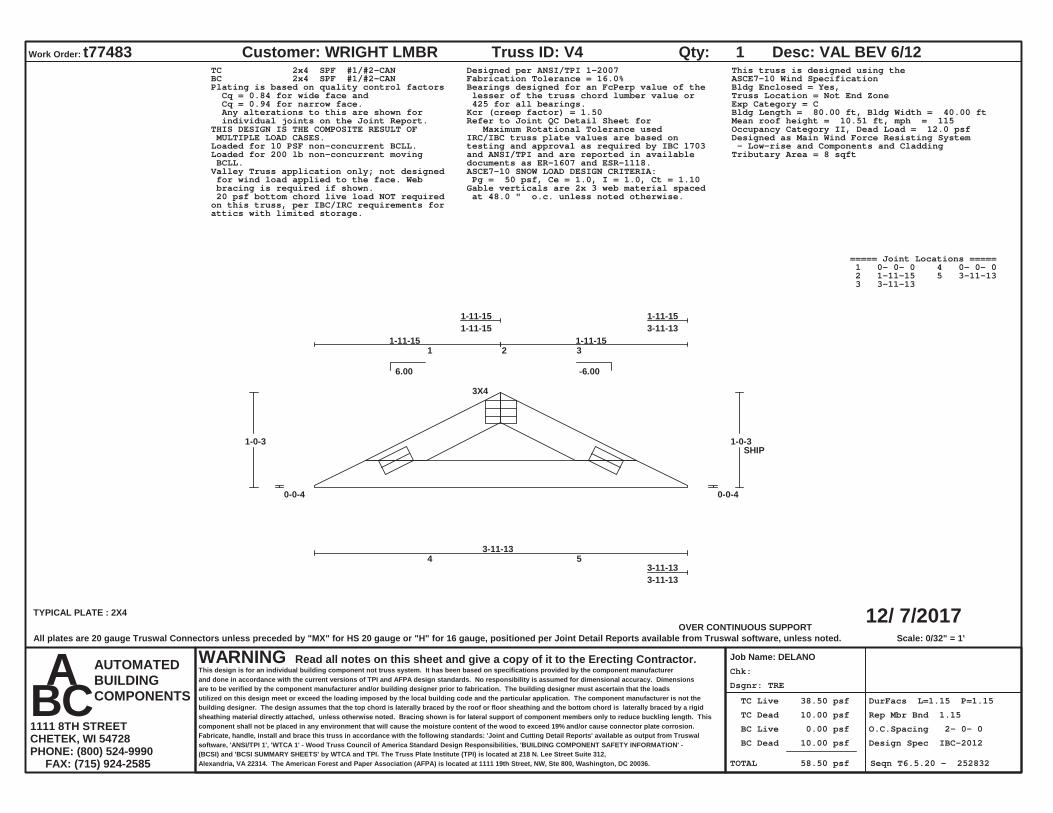
Dsgnr: TRE
Chk:
TC Live 38.50 psf
TC Dead 10.00 psf
BC Live 0.00 psf
BC Dead 10.00 psf
TOTAL 58.50 psf
DurFacs L=1.15 P=1.15
Rep Mbr Bnd 1.15
O.C.Spacing 2- 0- 0
Design Spec IBC-2012
Seqn T6.5.20 - 252832
12/ 7/2017
Work Order: t77483 Customer: WRIGHT LMBR
Job Name: DELANO
Truss ID: V4 Qty: 1 Desc: VAL BEV 6/12
WARNING Read all notes on this sheet and give a copy of it to the Erecting Contractor.This design is for an individual building component not truss system. It has been based on specifications provided by the component manufacturerand done in accordance with the current versions of TPI and AFPA design standards. No responsibility is assumed for dimensional accuracy. Dimensionsare to be verified by the component manufacturer and/or building designer prior to fabrication. The building designer must ascertain that the loadsutilized on this design meet or exceed the loading imposed by the local building code and the particular application. The component manufacturer is not thebuilding designer. The design assumes that the top chord is laterally braced by the roof or floor sheathing and the bottom chord is laterally braced by a rigidsheathing material directly attached, unless otherwise noted. Bracing shown is for lateral support of component members only to reduce buckling length. Thiscomponent shall not be placed in any environment that will cause the moisture content of the wood to exceed 19% and/or cause connector plate corrosion.Fabricate, handle, install and brace this truss in accordance with the following standards: 'Joint and Cutting Detail Reports' available as output from Truswalsoftware, 'ANSI/TPI 1', 'WTCA 1' - Wood Truss Council of America Standard Design Responsibilities, 'BUILDING COMPONENT SAFETY INFORMATION' -(BCSI) and 'BCSI SUMMARY SHEETS' by WTCA and TPI. The Truss Plate Institute (TPI) is located at 218 N. Lee Street Suite 312,Alexandria, VA 22314. The American Forest and Paper Association (AFPA) is located at 1111 19th Street, NW, Ste 800, Washington, DC 20036.
AUTOMATEDBUILDINGCOMPONENTS
A B C 1111 8TH STREETCHETEK, WI 54728PHONE: (800) 524-9990 FAX: (715) 924-2585
6.00 -6.00
OVER CONTINUOUS SUPPORTScale: 0/32" = 1'
1 2 3
1-11-151-11-15
1-11-153-11-13
4 5 3-11-133-11-13
TYPICAL PLATE : 2X4
3X4
3-11-13
0-0-4
1-0-3
0-0-4
1-0-3
1-11-15 1-11-15
SHIP
TC 2x4 SPF #1/#2-CANBC 2x4 SPF #1/#2-CAN
Designed per ANSI/TPI 1-2007Fabrication Tolerance = 16.0%Bearings designed for an FcPerp value of the lesser of the truss chord lumber value or 425 for all bearings.
Plating is based on quality control factors Cq = 0.84 for wide face and Cq = 0.94 for narrow face. Any alterations to this are shown for individual joints on the Joint Report.
Kcr (creep factor) = 1.50Refer to Joint QC Detail Sheet for Maximum Rotational Tolerance usedTHIS DESIGN IS THE COMPOSITE RESULT OF
MULTIPLE LOAD CASES. IRC/IBC truss plate values are based ontesting and approval as required by IBC 1703and ANSI/TPI and are reported in availabledocuments as ER-1607 and ESR-1118.
Loaded for 10 PSF non-concurrent BCLL.Loaded for 200 lb non-concurrent moving BCLL.
ASCE7-10 SNOW LOAD DESIGN CRITERIA: Pg = 50 psf, Ce = 1.0, I = 1.0, Ct = 1.10
Valley Truss application only; not designed for wind load applied to the face. Web bracing is required if shown. Gable verticals are 2x 3 web material spaced
at 48.0 " o.c. unless noted otherwise.
This truss is designed using theASCE7-10 Wind SpecificationBldg Enclosed = Yes,Truss Location = Not End ZoneExp Category = CBldg Length = 80.00 ft, Bldg Width = 40.00 ftMean roof height = 10.51 ft, mph = 115Occupancy Category II, Dead Load = 12.0 psfDesigned as Main Wind Force Resisting System - Low-rise and Components and CladdingTributary Area = 8 sqft
20 psf bottom chord live load NOT requiredon this truss, per IBC/IRC requirements forattics with limited storage.
===== Joint Locations ===== 1 0- 0- 0 4 0- 0- 0 2 1-11-15 5 3-11-13 3 3-11-13
All plates are 20 gauge Truswal Connectors unless preceded by "MX" for HS 20 gauge or "H" for 16 gauge, positioned per Joint Detail Reports available from Truswal software, unless noted.
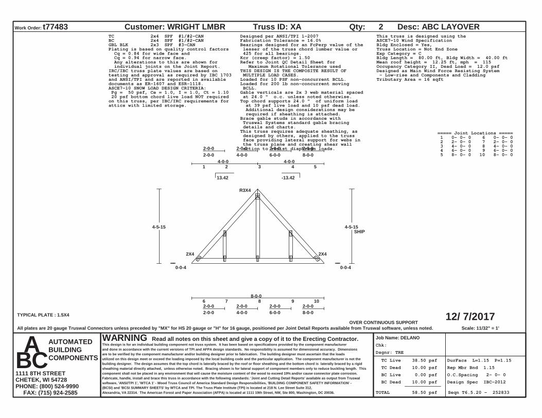
Dsgnr: TRE
Chk:
TC Live 38.50 psf
TC Dead 10.00 psf
BC Live 0.00 psf
BC Dead 10.00 psf
TOTAL 58.50 psf
DurFacs L=1.15 P=1.15
Rep Mbr Bnd 1.15
O.C.Spacing 2- 0- 0
Design Spec IBC-2012
Seqn T6.5.20 - 252833
12/ 7/2017
Work Order: t77483 Customer: WRIGHT LMBR
Job Name: DELANO
Truss ID: XA Qty: 2 Desc: ABC LAYOVER
WARNING Read all notes on this sheet and give a copy of it to the Erecting Contractor.This design is for an individual building component not truss system. It has been based on specifications provided by the component manufacturerand done in accordance with the current versions of TPI and AFPA design standards. No responsibility is assumed for dimensional accuracy. Dimensionsare to be verified by the component manufacturer and/or building designer prior to fabrication. The building designer must ascertain that the loadsutilized on this design meet or exceed the loading imposed by the local building code and the particular application. The component manufacturer is not thebuilding designer. The design assumes that the top chord is laterally braced by the roof or floor sheathing and the bottom chord is laterally braced by a rigidsheathing material directly attached, unless otherwise noted. Bracing shown is for lateral support of component members only to reduce buckling length. Thiscomponent shall not be placed in any environment that will cause the moisture content of the wood to exceed 19% and/or cause connector plate corrosion.Fabricate, handle, install and brace this truss in accordance with the following standards: 'Joint and Cutting Detail Reports' available as output from Truswalsoftware, 'ANSI/TPI 1', 'WTCA 1' - Wood Truss Council of America Standard Design Responsibilities, 'BUILDING COMPONENT SAFETY INFORMATION' -(BCSI) and 'BCSI SUMMARY SHEETS' by WTCA and TPI. The Truss Plate Institute (TPI) is located at 218 N. Lee Street Suite 312,Alexandria, VA 22314. The American Forest and Paper Association (AFPA) is located at 1111 19th Street, NW, Ste 800, Washington, DC 20036.
AUTOMATEDBUILDINGCOMPONENTS
A B C 1111 8TH STREETCHETEK, WI 54728PHONE: (800) 524-9990 FAX: (715) 924-2585
13.42 -13.42
OVER CONTINUOUS SUPPORTScale: 11/32" = 1'
1 2 3 4 5
2-0-02-0-0
2-0-04-0-0
2-0-06-0-0
2-0-08-0-0
6 7 8 9 102-0-02-0-0
2-0-04-0-0
2-0-06-0-0
2-0-08-0-0TYPICAL PLATE : 1.5X4
2X4
R3X4
2X4
8-0-0
0-0-4
4-5-15
0-0-4
4-5-15
4-0-0 4-0-0
SHIP
TC 2x4 SPF #1/#2-CANBC 2x4 SPF #1/#2-CANGBL BLK 2x3 SPF #3-CAN
Designed per ANSI/TPI 1-2007Fabrication Tolerance = 16.0%Bearings designed for an FcPerp value of the lesser of the truss chord lumber value or 425 for all bearings.
Plating is based on quality control factors Cq = 0.84 for wide face and Cq = 0.94 for narrow face. Any alterations to this are shown for individual joints on the Joint Report.
Kcr (creep factor) = 1.50Refer to Joint QC Detail Sheet for Maximum Rotational Tolerance usedTHIS DESIGN IS THE COMPOSITE RESULT OF MULTIPLE LOAD CASES.
IRC/IBC truss plate values are based ontesting and approval as required by IBC 1703and ANSI/TPI and are reported in availabledocuments as ER-1607 and ESR-1118.
Loaded for 10 PSF non-concurrent BCLL.Loaded for 200 lb non-concurrent moving BCLL.ASCE7-10 SNOW LOAD DESIGN CRITERIA:
Pg = 50 psf, Ce = 1.0, I = 1.0, Ct = 1.10 Gable verticals are 2x 3 web material spaced at 24.0 " o.c. unless noted otherwise.Top chord supports 24.0 " of uniform load at 39 psf live load and 10 psf dead load. Additional design considerations may be required if sheathing is attached.Brace gable studs in accordance with Truswal Systems standard gable bracing details and charts.This truss requires adequate sheathing, as designed by others, applied to the truss face providing lateral support for webs in the truss plane and creating shear wall action to resist diaphragm loads.
This truss is designed using theASCE7-10 Wind SpecificationBldg Enclosed = Yes,Truss Location = Not End ZoneExp Category = CBldg Length = 80.00 ft, Bldg Width = 40.00 ftMean roof height = 12.25 ft, mph = 115Occupancy Category II, Dead Load = 12.0 psfDesigned as Main Wind Force Resisting System - Low-rise and Components and CladdingTributary Area = 16 sqft
20 psf bottom chord live load NOT requiredon this truss, per IBC/IRC requirements forattics with limited storage.
===== Joint Locations ===== 1 0- 0- 0 6 0- 0- 0 2 2- 0- 0 7 2- 0- 0 3 4- 0- 0 8 4- 0- 0 4 6- 0- 0 9 6- 0- 0 5 8- 0- 0 10 8- 0- 0
All plates are 20 gauge Truswal Connectors unless preceded by "MX" for HS 20 gauge or "H" for 16 gauge, positioned per Joint Detail Reports available from Truswal software, unless noted.

Dsgnr: TRE
Chk:
TC Live 38.50 psf
TC Dead 10.00 psf
BC Live 0.00 psf
BC Dead 10.00 psf
TOTAL 58.50 psf
DurFacs L=1.15 P=1.15
Rep Mbr Bnd 1.15
O.C.Spacing 2- 0- 0
Design Spec IBC-2012
Seqn T6.5.20 - 252834
12/ 7/2017
Work Order: t77483 Customer: WRIGHT LMBR
Job Name: DELANO
Truss ID: XB Qty: 1 Desc: ABC LAYOVER
WARNING Read all notes on this sheet and give a copy of it to the Erecting Contractor.This design is for an individual building component not truss system. It has been based on specifications provided by the component manufacturerand done in accordance with the current versions of TPI and AFPA design standards. No responsibility is assumed for dimensional accuracy. Dimensionsare to be verified by the component manufacturer and/or building designer prior to fabrication. The building designer must ascertain that the loadsutilized on this design meet or exceed the loading imposed by the local building code and the particular application. The component manufacturer is not thebuilding designer. The design assumes that the top chord is laterally braced by the roof or floor sheathing and the bottom chord is laterally braced by a rigidsheathing material directly attached, unless otherwise noted. Bracing shown is for lateral support of component members only to reduce buckling length. Thiscomponent shall not be placed in any environment that will cause the moisture content of the wood to exceed 19% and/or cause connector plate corrosion.Fabricate, handle, install and brace this truss in accordance with the following standards: 'Joint and Cutting Detail Reports' available as output from Truswalsoftware, 'ANSI/TPI 1', 'WTCA 1' - Wood Truss Council of America Standard Design Responsibilities, 'BUILDING COMPONENT SAFETY INFORMATION' -(BCSI) and 'BCSI SUMMARY SHEETS' by WTCA and TPI. The Truss Plate Institute (TPI) is located at 218 N. Lee Street Suite 312,Alexandria, VA 22314. The American Forest and Paper Association (AFPA) is located at 1111 19th Street, NW, Ste 800, Washington, DC 20036.
AUTOMATEDBUILDINGCOMPONENTS
A B C 1111 8TH STREETCHETEK, WI 54728PHONE: (800) 524-9990 FAX: (715) 924-2585
13.42 -13.42
OVER CONTINUOUS SUPPORTScale: 5/16" = 1'
1 2 3 4 5
2-2-82-2-8
2-0-04-2-8
2-0-06-2-8
2-2-88-5-0
6 7 8 9 102-2-82-2-8
2-0-04-2-8
2-0-06-2-8
2-2-88-5-0
TYPICAL PLATE : 1.5X4
2X4
R3X4
2X4
8-5-0
0-0-4
4-8-12
0-0-4
4-8-12
4-2-8 4-2-8
SHIP
TC 2x4 SPF #1/#2-CANBC 2x4 SPF #1/#2-CANGBL BLK 2x3 SPF #3-CAN
Designed per ANSI/TPI 1-2007Fabrication Tolerance = 16.0%Bearings designed for an FcPerp value of the lesser of the truss chord lumber value or 425 for all bearings.
Plating is based on quality control factors Cq = 0.84 for wide face and Cq = 0.94 for narrow face. Any alterations to this are shown for individual joints on the Joint Report.
Kcr (creep factor) = 1.50Refer to Joint QC Detail Sheet for Maximum Rotational Tolerance usedTHIS DESIGN IS THE COMPOSITE RESULT OF MULTIPLE LOAD CASES.
IRC/IBC truss plate values are based ontesting and approval as required by IBC 1703and ANSI/TPI and are reported in availabledocuments as ER-1607 and ESR-1118.
Loaded for 10 PSF non-concurrent BCLL.Loaded for 200 lb non-concurrent moving BCLL.ASCE7-10 SNOW LOAD DESIGN CRITERIA:
Pg = 50 psf, Ce = 1.0, I = 1.0, Ct = 1.10 Gable verticals are 2x 3 web material spaced at 24.0 " o.c. unless noted otherwise.Top chord supports 24.0 " of uniform load at 39 psf live load and 10 psf dead load. Additional design considerations may be required if sheathing is attached.Brace gable studs in accordance with Truswal Systems standard gable bracing details and charts.This truss requires adequate sheathing, as designed by others, applied to the truss face providing lateral support for webs in the truss plane and creating shear wall action to resist diaphragm loads.
This truss is designed using theASCE7-10 Wind SpecificationBldg Enclosed = Yes,Truss Location = Not End ZoneExp Category = CBldg Length = 80.00 ft, Bldg Width = 40.00 ftMean roof height = 12.36 ft, mph = 115Occupancy Category II, Dead Load = 12.0 psfDesigned as Main Wind Force Resisting System - Low-rise and Components and CladdingTributary Area = 17 sqft
20 psf bottom chord live load NOT requiredon this truss, per IBC/IRC requirements forattics with limited storage.
===== Joint Locations ===== 1 0- 0- 0 6 0- 0- 0 2 2- 2- 8 7 2- 2- 8 3 4- 2- 8 8 4- 2- 8 4 6- 2- 8 9 6- 2- 8 5 8- 5- 0 10 8- 5- 0
All plates are 20 gauge Truswal Connectors unless preceded by "MX" for HS 20 gauge or "H" for 16 gauge, positioned per Joint Detail Reports available from Truswal software, unless noted.

1
SUBCONTRACTOR/SUPPLIER CONTRACT FOR CONCESSIONS BUILDING AT THE DELANO CENTRAL PARK
THIS CONTRACT is made and executed the _____ day of November, 2017(“Agreement”), by and between the City of Delano, a Minnesota municipal corporation,hereinafter referred to as the "City", and ________________________________, a Minnesota corporation, hereinafter referred to as "Contractor".
WHEREAS, the City is constructing a Concessions Building at Central Park, in accordance with plans dated September 22, September 26, and December 12, 2017, which have been reviewed by the Contractor (“Concessions Building Project”); and
WHEREAS, the City wishes to retain Contractor to supply materials and/or complete construction of one portion of the Concessions Building Project, as more fully described on Exhibit A (“Work”) according to the terms and conditions of this Agreement.
NOW, THEREFORE, in consideration of the mutual covenants and agreements hereinafter set forth and for other good and valuable consideration, the receipt and sufficiency of which are hereby acknowledged, the parties hereto agree as follows:
1. Agreement: The term “Agreement” shall include this Contract and the Work described on Exhibit A.
2. Contractor’s Duties: Contractor shall fully and satisfactorily perform the Work in full compliance with the Agreement. Contractor shall complete the Work by February 10,2018, or another date as amended and mutually agreed upon by Owner and Contractor. Any changes in the scope of the Work which may result in an increase to the compensation due the Contractor shall require prior written approval by the City.
3. Coordination: Contractor understands that there is no general contract for the Concessions Building Project and no general contractor. The City is acting as its own construction manager to coordinate all portions of the work for the Concessions Building Project. Accordingly, Contractor agrees to carefully coordinate the Work with the City to ensure that the Work is performed at an appropriate sequence and in coordination with other portions of thework for the Concessions Building Project. The City retains full and sole discretion to adjust the schedule and sequence of the Work and all other work on the Concessions Building Project as it deems appropriate.
4. Compensation: The City agrees to pay Contractor __________ as full and complete payment for the Work.
5. Payment: Contractor shall submit to the City, on a monthly basis, itemized pay requests for Work completed under this Agreement. City shall pay all pay requests within 35 days of acceptance of the pay request by the City and acceptance of that portion of the Work
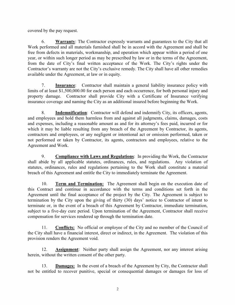
2
covered by the pay request.
6. Warranty: The Contractor expressly warrants and guarantees to the City that all Work performed and all materials furnished shall be in accord with the Agreement and shall be free from defects in materials, workmanship, and operation which appear within a period of one year, or within such longer period as may be prescribed by law or in the terms of the Agreement,from the date of City’s final written acceptance of the Work. The City’s rights under the Contractor’s warranty are not the City’s exclusive remedy. The City shall have all other remedies available under the Agreement, at law or in equity.
7. Insurance: Contractor shall maintain a general liability insurance policy with limits of at least $1,500,000.00 for each person and each occurrence, for both personal injury and property damage. Contractor shall provide City with a Certificate of Insurance verifying insurance coverage and naming the City as an additional insured before beginning the Work.
8. Indemnification: Contractor will defend and indemnify City, its officers, agents, and employees and hold them harmless from and against all judgments, claims, damages, costs and expenses, including a reasonable amount as and for its attorney’s fees paid, incurred or for which it may be liable resulting from any breach of the Agreement by Contractor, its agents, contractors and employees, or any negligent or intentional act or omission performed, taken or not performed or taken by Contractor, its agents, contractors and employees, relative to theAgreement and Work.
9. Compliance with Laws and Regulations: In providing the Work, the Contractor shall abide by all applicable statutes, ordinances, rules, and regulations. Any violation of statutes, ordinances, rules and regulations pertaining to the Work shall constitute a material breach of this Agreement and entitle the City to immediately terminate the Agreement.
10. Term and Termination: The Agreement shall begin on the execution date of this Contract and continue in accordance with the terms and conditions set forth in the Agreement until the final acceptance of the project by the City. The Agreement is subject to termination by the City upon the giving of thirty (30) days’ notice to Contractor of intent to terminate or, in the event of a breach of this Agreement by Contractor, immediate termination, subject to a five-day cure period. Upon termination of the Agreement, Contractor shall receive compensation for services rendered up through the termination date.
11. Conflicts: No official or employee of the City and no member of the Council of the City shall have a financial interest, direct or indirect, in the Agreement. The violation of this provision renders the Agreement void.
12. Assignment: Neither party shall assign the Agreement, nor any interest arising herein, without the written consent of the other party.
13. Damages: In the event of a breach of the Agreement by City, the Contractor shall not be entitled to recover punitive, special or consequential damages or damages for loss of
3
business.
14. Data Practices Act: Contractor shall at all times abide by the Minnesota Government Data Practices Act, Minn. Stat. § 13.01, et seq., to the extent that the Act is applicable to data and documents in the hands of Contractor.
15. Audits: The books, records, documents, and accounting procedures and practices of Contractor or other parties relevant to the Agreement are subject to examination by the City and either Legislative Auditor or the State Auditor for a period of six years after the effective date of the Agreement.
16. Independent Contractor: Contractor is an independent contractor engaged by City to perform the Work and as such (i) shall employ such persons as it shall deem necessary and appropriate for the performance of its obligations pursuant to the Agreement, who shall be employees, and under the direction, of Contractor and in no respect employees of City, and (ii) shall have no authority to employ persons, or make purchases of equipment on behalf of City, or otherwise bind or obligate City. No statement herein shall be construed so as to find the Contractor an employee of the City.
17. Income Tax Withholding: No final payment shall be made to Contractor until ithas provided satisfactory evidence to the City that it and each of its subcontracts has complied with the provisions of Minn. Stat. § 290.92 relating to withholding of income taxes upon wages. A certificate by the Commissioner of Revenue shall satisfy this requirement.
18. Workers’ Compensation: Contractor represents and warrants that it has and will maintain during the performance of the Agreement workers’ compensation insurance coverage required pursuant to Minn. Stat. § 176.181, subd. 2 and that the certificate of insurance or the written order of the Commissioner of Commerce permitting self insurance of workers’compensation insurance coverage provided to the City prior to execution of this Contract is current and in force and effect.
19. Non-Discrimination: In performance of the Agreement, Contractor shall not discriminate on the grounds of or because of race, color, creed, religion, national origin, sex, marital status, status with regards to public assistance, disability, sexual orientation, or age against any employee of Contractor, any subcontractor of it, or any applicant for employment. Contractor shall include a similar provision in all contracts with subcontractors to the Agreement.Contractor further agrees to comply with all aspects of the Minnesota Human Rights Act, Minn. Stat. § 363.01, et seq., Title VII of the Civil Rights Act of 1964, and the Americans with Disabilities Act of 1990.
20. Counterparts: This Contract may be executed in multiple counterparts each of which shall be considered an original.
21. Whole Agreement: The Agreement constitutes the final and complete agreement of the parties and shall supersede and replace any prior oral or written agreements between the
City and Contractor. Any subsequent modification must be in writing signed by both parties.
22. Governing Law: The Agreement shall be governed and construed under the laws of the State of Minnesota and the parties agree that any actions arising out of or related to theAgreement shall be venued in the State of Minnesota, Wright County District Court.
23. Mediation: Each dispute, claim or controversy arising from or related to theAgreement shall be subject to mediation as a condition precedent to initiating arbitration or legal or equitable actions by either party.
IN WITNESS WHEREOF, the parties to this Agreement have hereunto set their hands as of the date set forth above.
CONTRACTOR
By ________________________________
Its ________________________________
CITY OF DELANO
By ________________________________
Its ________________________________
By_________________________________
Its ________________________________