report.pdf
TRANSCRIPT
i
DS-CDMA systems using Chaotic complex
Bernoulli Spreading codes and Turbo Codes Submitted in partial fulfilment of the requirements
Of the degree of
Bachelor of Technology
Submitted By:
Snehal Chipade (114254)
Piyush Meshram (114243)
SUPERVISOR
Dr. S. Anuradha
(Assistant Professor)
ELECTRONICS AND COMMUNICATION ENGINEERING
NATIONAL INSTITUTE OF TECHNOLOGY
WARANGAL
2015

ii
APPROVAL SHEET
This Project Work entitled by DS-CDMA systems using Chaotic complex Bernoulli Spreading
codes and Turbo Codes by Snehal Chipade and Piyush Meshram is approved for the Degree
of Bachelor of Technology, Electronics and Communication Engineering.
Examiners:
Supervisor:
Dr S. Anuradha
(Assistant Professor Department of Electronics and communication Engineering)
Chairman:
Dr. T. Kishore Kumar
(Head, Department of Electronics and communication Engineering)
Date: _____________________________
Place: _____________________________

iii
Declaration
We declare that this written submission represents our ideas in our own words and where other
ideas or words have been included, we have adequately cited and referenced the original sources.
We also declare that we have adhered to all principles of academic honesty and integrity and have
not misrepresented or fabricated or falsified any idea / data / fact / source in our submission. We
understand that any violation of the above will be a cause for disciplinary action by the Institute
and can also evoke penal action from the sources which have thus not been properly cited or from
whom proper permission has not been taken when needed.
_________________
Snehal Chipade
(UG114254)
_________________
Piyush Meshram
(UG114243)
Date:

iv
Certificate
This is to certify that the project work entitled “DS-CDMA systems using Chaotic complex
Bernoulli Spreading codes and Turbo Codes” is a bonafide record of work carried out by
“Snehal Chipade (UG114254) and Piyush Meshram (UG114243) ” submitted to the faculty
of “Electronics and Communications Engineering Department”, in partial fulfilment of the
requirements for the award of the degree of Bachelor of Technology in “Electronics and
Communications Engineering” at National Institute of Technology, Warangal during the academic
year 2014-2015.
Dr . T .Kishore Kumar Dr . S. Anuradha
Head of the Department Assistant Professor
Department of Department of
Electronics and Communication Engineering Electronics and Communication Engineering
NIT Warangal NIT Warangal

v
Specifications
Modulation Technique Binary phase shift keying
Data Rate 9600 bps without FEC
4800 bps with FEC
Number of bits transmitted per user 10000
Number of users 30 (max.)
Signal to Noise ratio 8 decibels
Spreading sequences Gold sequences
Chaotic Bernoulli sequences
Bit Error Rate 10-4
Spreading factor 1023
Channels Additive white Gaussian noise channel
Rayleigh fading channel
Multiple access interference model
Channel coding Turbo coding
1/3 RSC convolution coding - 2
Trellis structure- poly2trellis(4, [13 15], 13)
vi
Abstract
The most important goal of spreading spectrum communication system is to protect
communication signals against interference and exploitation of information by unintended
listeners. In fact, low probability of detection and low probability of intercept are two important
parameters to increase the performance of the system. In Direct Sequence Code Division Multiple
Access (DS-CDMA) systems, these properties are achieved by multiplying the data information in
spreading sequences. Proper correlation function and more freedom of choice of appropriate
codeswith chaotic sequences results in numerous applications for constructing spreading codes. In
this paper, use of two-dimensional Bernoulli chaotic sequences is proposed as spreading codes.
The performance of a multi-user DS-CDMA system will be evaluated by applying these sequences
under Additive White Gaussian Noise (AWGN), Rayleigh fading channel and Multiple access
interference model. Simulation results indicate improvement of the performance in comparison
with conventional spreading codes like Gold codes as well as similar complex chaotic spreading
sequences. Besides, error control coding using turbo coders gives significant improvement in
performance of the system. Turbo coding is most popular technique for error control.
vii
Content
Specifications ………………………………………………………..v
Abstract ……………………………………………………………...vi
List of Figures ……………………………………………………….ix
List of Tables ………………………………………………………..xi
Abbreviation Notation and Nomenclature ………………………….xii
1. Introduction
1.1 Overview ………………………………………………………...…...1
1.2 Objective……………………………………………………………...2
1.3 Outline……………………………………………….……………......3
2. Literature review ………………………………………..…………4
3. Spread spectrum and multiple access system
3.1 Multiple access techniques …………………………………………..7
3.2 CDMA system ..………………………………………………………8
3.3 Spread spectrum modulation technique ………..…………………...10
4. Spreading code for CDMA system
4.1 Overview …………………………………………………................13
4.2 Factors affecting choice of spreading code …………………………13
` 4.3 Pseudo random sequences …………………….…………………….15
5. Introduction to chaotic sequence
5.1 Overview..…………………………………………………...............18
5.2 Chaotic system ……………………………………………………...18
5.2 Chaotic sequence ……..…………………………………………….19

viii
6. Error control coding technique
6.1 Introduction . …………………..…...………………………………23
6.2 Error control coding technique…….……………..……………… ...24
7. Multiple access interference
7.1 Motivation for MAI characterization ……..…………..…………… 34
7.2 Gaussian approximation ….………………...……………………… 35
7.3 Discrete analysis of MAI ..……………………………….…………36
8. Results ………………………………………..………………..…37
9. Conclusion ……………………………………………………..…44
Literature cited ...………………………………………………...….45
Acknowledgement ………………………………………………….47

ix
List of Figures
Fig. 3.1 Working of FDMA and TDMA …………………………………………………..... 8
Fig. 3.2 Working of CDMA system…………………………………………………………. 8
Fig. 3.3 CDMA System…………………………………………………………… …………9
Fig. 3.4 Block diagram of a spread spectrum system ………………………………………..10
Fig. 4.1 m-sequences generator …………………………………………………………… 16
Fig. 4.2 Gold code sequence generator configuration. ………………………………………17
Fig. 5.1 Block diagram of DS-CDMA transmitter with complex spreading sequence ………21
Fig 6.1 Digital Communication Model ………………………………………………….…...24
Fig 6.2 Convolutional Encoder with a=1 n=2and r=1/2 …………………………………..…28
Fig 6.3 Turbo Code …………………………………………………………………………. 28
Fig.6.4 Decoding of Concatenated Code with feedback …………………………………… 29
Fig. 6.5.A) No Systemic Non Recursive convolutional code with polynomial 13,15……….30
Fig. 6.5.B) Recursive system recursive convolution (RSC) code with polynomial
13(recursivity), 15(parity) ………………………………………………….. 30
Fig. 6.6 A Turbo code with component code 13,15. ………………………………………. 30
Fig. 6.7 A Turbo decoder……………………………………………………… …………….32
Fig. 8.1 Auto- correlation vs time…………………………………………………… ………37
Fig. 8.2 Cross-correction vs time ……………………………………………………………..37
Fig.8.3 Auto correlation of gold and Bernoulli sequences………………………………… .. 38
Fig. 8.4 Cross – correlation of gold and Bernoulli sequence ……………………..…………. 38
x
Fig. 8.5 Performance comparison of Gold and Bernoulli sequence in AWGN channel ……..39
Fig. 8.6 Performance Comparison of Gold and Bernoulli sequence in AWGN channel
with MAI ….…………………………………………………………………………39
Fig. 8.7 performance comparison of gold and Bernoulli sequence in Rayleigh
fading channel. ………………………………………………………………………40
Fig. 8.8 Comparison of Gold and Bernoulli sequence with and without turbo coding………40
Fig. 8.9 Turbo Code Performance for different number of iteration in AWGN channel
without MAI ……………………………………………………………………...…41
Fig. 8.10 Turbo Code Performance for different number of iteration in AWGN channel
with MAI……...………… …………………………………………………………...41
Fig. 8.11 Turbo Code Performance for different number of iteration in Rayleigh
fading channel… ……………………………………………………………………..42
Fig. 8.12 BER vs No. of users in Gold and Bernoulli’s sequence …...………………………42
xi
List of Tables
Table 8.1 BER comparison for Gold and Bernoulli sequences……………………………... 43
Table 8.2 BER comparison for different channel models ……………………………….43
Table 8.3 BER comparison for different number iterations in turbo decoder . ……………...43

xii
Abbreviation Notation and Nomenclature
ACF auto-correlation function
AWGN additive white Gaussian noise
BER bit error ratio
CCF cross-correlation function
CDMA code division multiple access
CIR carrier to interference ratio
CLB chip level based
DS direct sequence
ISI inter symbol interference
LFSR linear feedback shift register
MAI multiple access interference
MUD multi user detection
PN pseudo noise
PSD power spectral density
BPSK binary phase shift keying
QPSK quadrature phase shift keying
SNR signal to noise ratio
SS spread spectrum
TDL tapped-delay-line
FEC Forward error correction
RSC recursive systematic coding
1
Chapter 1
Introduction
1.1 Overview
Code Division Multiple Access (CDMA) cellular network is a promising wireless
technology and it has been in the focus of academic research since many years. In comparison
with Time Division Multiple Access (TDMA) and Frequency Division Multiple Access
(FDMA), CDMA is found to be more attractive for wireless access for its numerous advantages
like frequency reuse and multiuser detection. The performance of CDMA based wireless
systems is largely based on the characteristics of user specific spreading codes. These codes
spread the original information signal to a large bandwidth and also provide unique identity to
the various channels originating from base station as well as mobile station. At the receiver
side, the original information signal is recovered by correlating the received signal with the
synchronized replica of the spreading code. Thus spreading codes play an important role in
CDMA system to spread the user signals and distinguish among different users.
Multiple Access Interference (MAI) generally occurs in CDMA system due to non-
orthogonality between spreading codes and so it restricts the capacity of CDMA systems. The
MAI arising due to cross-correlation between the spreading codes assigned to different users.
A family of spreading codes for which cross- correlation function is zero at zero time shifts is
known as orthogonal codes. Orthogonal spreading can only be used if all the users are
synchronized, as the cross-correlation value between sequences at different time shifts is not
zero. MAI terms cannot be made zero as it is impossible to design spreading codes that have
2
zero cross correlation with all shifts of other spreading codes. It is desired to make MAI terms
as minimum as possible by minimizing the magnitude of cross correlation.
Inter Symbol Interference (ISI) is another limiting factor in CDMA system which is a
function of autocorrelation values of the used spreading codes. In order to minimize the ISI
effect Auto-Correlation Function (ACF) of a spreading code should be impulsive type i.e. peak
value at zero time shift and minimum values at other shifts to distinguish the desired user at
receiver side from other users producing MAI.
1.2 Objective
Code Division Multiple Access (CDMA) is used as a multiple access technique in
telecommunications radio system that can transport multimedia traffic at high data rates. The
communications researchers have studied CDMA and are further developing it. In a CDMA
system availability of more number of codes, minimum magnitude of cross correlation,
impulsive peak auto correlation and BER performance plays a major role. So it is needed to
generate spreading code such that it support more number of user, good auto-correlation
property, good BER performance with better cross-correlation property which eliminate
undesirable effect like ISI, MAI by reducing the chance of false synchronization. Hence it is
desirable to have spreading codes which possess both impulsive Auto Correlation Function
(ACF) and all zero Cross Correlation Function (CCF) characteristics with large number of code
sets. Forward error control technique with turbo encoders and decoders is further applied to
achieve higher performance.
1.3 Problem Statement
a) To design chaotic Bernoulli sequences which gives better performance than
conventional gold sequences.
b) To apply error control techniques with turbo codes to improve BER.
3
1.4 Outline
Chapter 2 gives the literature review of the project.
Chapter 3 introduces different multiple access techniques and gives precise idea of DS-CDMA
system.
Chapter 4 introduces different spreading techniques used in DS-CDMA system. M-sequences
and gold sequences are discussed.
Chapter 5 introduces to chaotic system and sequences. Chaotic Bernoulli sequences are
discussed and importance of Bernoulli sequences due to its auto-correlation properties is
described.
Chapter 6 explains different error control coding techniques in brief. Turbo encoders and
decoders are introduced.
Chapter 7 gives MAI model used for simulation.
Chapter 8 include simulation results.

4
Chapter 2
Literature Review
In spreading spectrum systems, main information is spread in a wide bandwidth. One of
the main methods to spread the spectrum is Direct Sequence Code Division Multiple Access
(DS-CDMA) in which information of all users will be sent simultaneously at the same
frequency band. The spectrum will be spread by using the sequences with specialized features
which are called spreading sequences. Indeed, for each user, a particular sequence will be sent
instead of each information bit. The receiver uses the same spreading sequence to detect the
received data. As a result of spreading, the transmitted signal occupies more bandwidth than
the original message. Properties of spreading sequences are mainly determined by their auto-
correlation and cross-correlation.
The code should be orthogonal or quasi-orthogonal to each other in different delays, to
use in multipath channels ideally. The most commonly used sequences in DS-CDMA are
maximal length (m-sequence) and Gold, which are implementable by Linear Feedback Shift
Registers (LFSRs). In recent decades, using chaotic sequences as spreading codes has been of
great interest. Chaotic sequences, despite the deterministic nature, show the irregular and
pseudo-random behaviour. These sequences can be produced in arbitrary length and they are
entirely non-periodic. Due to extreme sensitivity of chaotic sequences in initial conditions,
numerous chaotic sequences with desired properties can be created. Generated chaotic
sequences are almost orthogonal with the low cross-correlation value that made them desirable
to be used in spread spectrum systems.[9]

5
Non-orthogonality between spreading codes in CDMA system users causes MAI which
consequently restricts the capacity of CDMA systems. Many strategies have been proposed to
moderate the effect of MAI, for example, multiuser detection can be employed to use multiple
user information for better detection of each user signal rather than using single conventional
detection. Here the conventional DS-CDMA detector follows a single user detection strategy
in which each user is detected separately without regard for the other users. So a better strategy
is multiuser detection, where information about multiple users is used to improve detection of
each individual user.
Unlike the conventional pseudo-noise sequences, chaotic sequences can be made by
simple recursive equations. These sequences with different characteristics and parameters have
been used in several references.[3][4][5][6].
In [6], it has been shown that chaotic sequences with exponentially vanishing auto-
correlation function can improve the performance of spreads spectrum systems.
In [11] and [2], chaotic sequences with negative autocorrelation at lag of 1 have been
studied as a near optimal spreading sequence.
Complex chaotic sequences are introduced in [3] and [4], and performance of the DS-
CDMA system based on them has been analyzed. The spread spectrum system can have better
performance in terms of cross-correlation and the average Bit Error Rate (BER), using two-
dimensional or complex sequences. This is due to more flexibility to select real and imaginary
parts of each sequence.
In [3], the complex IKEDA map is used to generate two dimensional chaotic sequences.
In a multi-user asynchronous DS-CDMA systems (such as the reverse link of cellular systems),
each user is affected by interference of other users. The average interference can be described
by the auto-correlation function of codes. So by designing the sequences with appropriate auto-
correlation functions, the proper spreading codes sequences can be produced. This idea has
been used to proper design of one-dimensional chaos spreading sequences in [10].
When digital data is transmitted through a communication channel, errors are embedded

6
into it. Error Detection Coding is used to detect and correct the errors in the received
information [8]. Most popular ECC is Turbo Coding. Turbo Codes are also known as Parallel
Concatenated codes and the decoding complexity is small for the dimension of code, whereas
the code length possible is very long. The bounds of Shannon’s Limit also become achievable
for all practical purposes because the decoding complexity becomes small [1]. Use of turbo
coding under MAI channel model is given in [7].
Here, the idea of utilizing two Bernoulli chaotic sequences to form two-dimensional
(complex) sequences is presented. This project shows that correlation properties of new
sequences are better than conventional gold sequences. We have used turbo coding technique
to further achieve better performance. Additionally, according to the new complex sequences,
it is expected that spreading codes with a better cross-correlation than the one-dimensional
codes can be selected.
7
Chapter 3
Spread Spectrum and multiple access system
3.1 Multiple Access Techniques
The main task of the communication system designer is to make the best use of the
system resources. The challenge is to make the most efficient use of the Radio Frequency (RF)
bandwidth. Frequency Division Multiple Access (FDMA), Time Division Multiple Access
(TDMA) and Code Division Multiple Access (CDMA) are the three major access techniques,
used to share the available bandwidth in a mobile communication system to provide group of
users in one RF channel. CDMA technique is a wideband system and it comes under spread
spectrum multiple access technique. Figure 3.2 (a) shows the working of FDMA, in which every
user communicate over an individual channel over the whole period of time. FDMA is often
referred to as the first generation system. In TDMA system, more than one user can share the
same channel at the same time as shown in Figure 3.2 (b). This multiple access method is used
in the Global System for Mobiles (GSM) system, which was the first digital cellular standard
for voice communications and is termed as the second generation system.

8
Fig.3.1 Working of FDMA and TDMA system
Figure 3.2 shows the working of CDMA system. In CDMA system all users share a
common channel in time and frequency. All users transmit continuously over the full channel
bandwidth but the users are separated only in space.
Fig.3.2 Working of CDMA system
3.2 CDMA System
CDMA is a multiple access technique that uses spread-spectrum modulation by each
accessing party with its own unique spreading code, with all accessing parties sharing the same
spectrum. Spread spectrum modulation is accomplished by means of PN (Pseudo Noise) code.
This is shown in the Figure 3.4 as given below. Here, Ci (t) and di (t) represent the PN code and
information sequence used for ith user where, i = 1, 2… n. Here the information sequence is
modulated by the wideband spreading signal thereby spreading the information signal spectrum
to a substantially greater bandwidth prior to transmission. It is important to recognize that
CDMA can only be accomplished by spread-spectrum modulation, while spread spectrum
modulation does not mean CDMA.
9
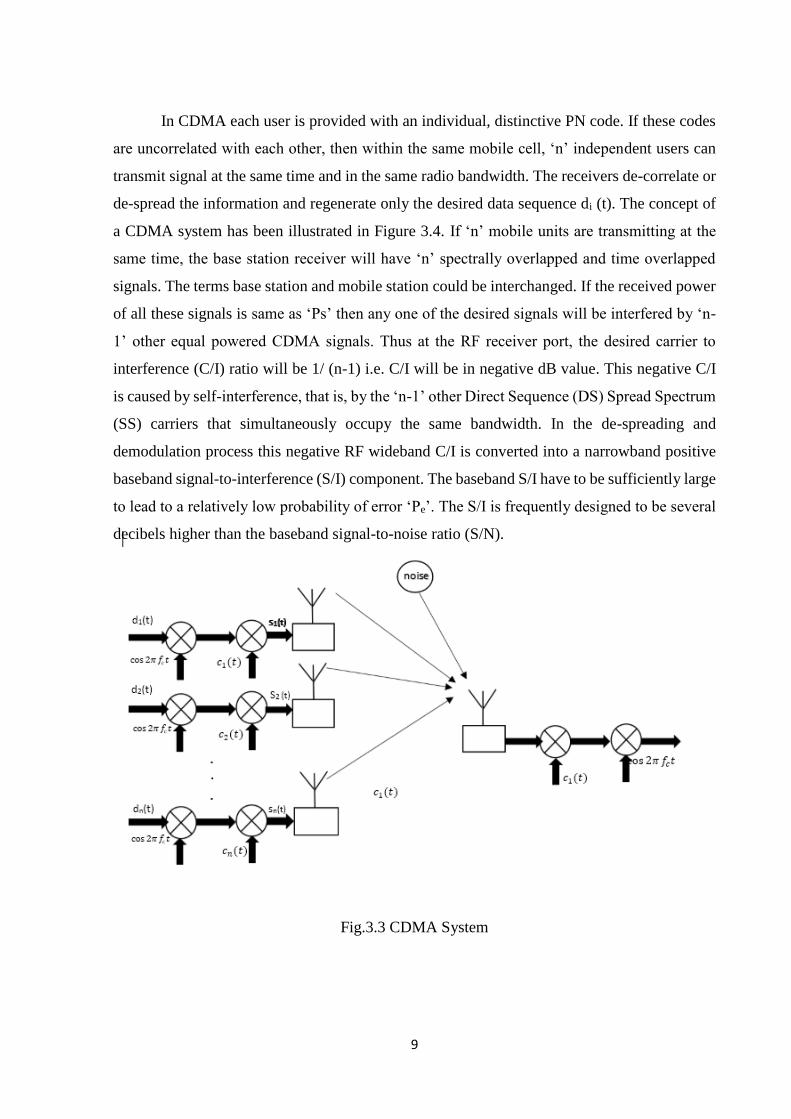
In CDMA each user is provided with an individual, distinctive PN code. If these codes
are uncorrelated with each other, then within the same mobile cell, ‘n’ independent users can
transmit signal at the same time and in the same radio bandwidth. The receivers de-correlate or
de-spread the information and regenerate only the desired data sequence di (t). The concept of
a CDMA system has been illustrated in Figure 3.4. If ‘n’ mobile units are transmitting at the
same time, the base station receiver will have ‘n’ spectrally overlapped and time overlapped
signals. The terms base station and mobile station could be interchanged. If the received power
of all these signals is same as ‘Ps’ then any one of the desired signals will be interfered by ‘n-
1’ other equal powered CDMA signals. Thus at the RF receiver port, the desired carrier to
interference (C/I) ratio will be 1/ (n-1) i.e. C/I will be in negative dB value. This negative C/I
is caused by self-interference, that is, by the ‘n-1’ other Direct Sequence (DS) Spread Spectrum
(SS) carriers that simultaneously occupy the same bandwidth. In the de-spreading and
demodulation process this negative RF wideband C/I is converted into a narrowband positive
baseband signal-to-interference (S/I) component. The baseband S/I have to be sufficiently large
to lead to a relatively low probability of error ‘Pe’. The S/I is frequently designed to be several
decibels higher than the baseband signal-to-noise ratio (S/N).
Fig.3.3 CDMA System
10
3.3 Spread Spectrum Modulation Techniques
Spread spectrum techniques employ a transmission bandwidth that is much greater than the
minimum required signal bandwidth. While the system is very bandwidth inefficient for a single
user, the advantage of spread spectrum is that many users can simultaneously use the same
bandwidth without significantly interfering with one another. In a multiple-user, Multiple
Access Interference (MAI) environment, spread spectrum systems become very bandwidth
efficient.
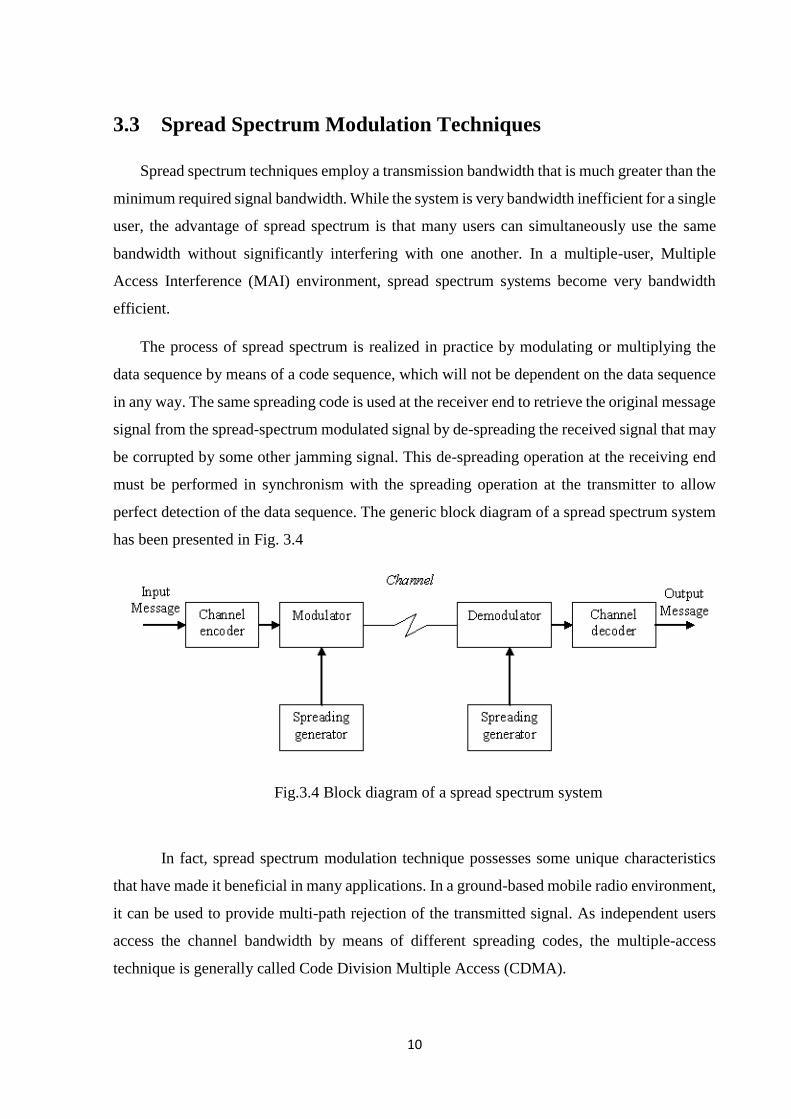
The process of spread spectrum is realized in practice by modulating or multiplying the
data sequence by means of a code sequence, which will not be dependent on the data sequence
in any way. The same spreading code is used at the receiver end to retrieve the original message
signal from the spread-spectrum modulated signal by de-spreading the received signal that may
be corrupted by some other jamming signal. This de-spreading operation at the receiving end
must be performed in synchronism with the spreading operation at the transmitter to allow
perfect detection of the data sequence. The generic block diagram of a spread spectrum system
has been presented in Fig. 3.4
Fig.3.4 Block diagram of a spread spectrum system
In fact, spread spectrum modulation technique possesses some unique characteristics
that have made it beneficial in many applications. In a ground-based mobile radio environment,
it can be used to provide multi-path rejection of the transmitted signal. As independent users
access the channel bandwidth by means of different spreading codes, the multiple-access
technique is generally called Code Division Multiple Access (CDMA).

11
In order to enhance the bandwidth of the message signal, spreading codes are
judiciously used in such a system. Binary message sequence {mk} and code sequence {ck} can
be represented by different types of line code. Normally, they are represented by polar non-
return-to-zero form where binary ‘1’ is characterized by a rectangular pulse of unit positive
amplitude and a rectangular pulse of unit negative amplitude symbolize a binary ‘0’.
Accordingly, two types of time varying signal, m (t) and c (t), can be defined in accordance
with information sequence and spreading sequence respectively. At the transmitting end, the
spread-spectrum modulated signal s (t) is generated in accordance with the following equation:
s (t) = c (t).m (t) (1)
The message signal m (t) is a narrowband signal and the spreading signal c (t) is of
wideband in nature. Due to the effect of multiplication, the product signal s (t) has a wideband
spectrum. The process of multiplication has the effect of chopping the data sequence m (t) into
a number of small time increments, called chips. The signal s (t) is used to modulate a high
frequency carrier signal in case of pass band communication.
The received signal r (t) contains the transmitted signal and additive interference signal
that is directed towards the receiver in order to disrupt the communication. Thus the received
signal can be written as:
r (t) = s (t) + n (t) = c (t).m (t) + n(t) (2)
where, n (t) denotes the narrowband noise signal.
In order to retrieve the information bearing signal m(t) from the noise corrupted received
signal r(t), the presence of the spreading signal in perfect synchronism with that of the
transmitter is a necessary criterion at the receiver. In fact, at the receiving end both spreading
and de-spreading operations are done simultaneously on two components of the received signal.
The first component s (t) is wideband in nature, whereas n (t) is a narrow band jamming signal.
The effect of the spreading signal c (t) at the receiving end is to de-spread the wideband signal
s (t) while spreading the narrowband signal n (t) as in transmitter. For the proper reception of
the information sequence, the receiver must operate synchronously with the transmitter.
Receiver of a baseband transmission model consists of a multiplier, followed by a low pass

12
filter. In order to facilitate the coherent detection, presence of a locally generated carrier signal
is an additional mandatory requirement in the receiver of such a system. The output of the
multiplier, x (t), is given by:
x(t) = r(t).c(t) = s(t).c(t) + n(t).c(t) = m(t).c2(t) + n(t).c(t) (3)
Thus the multiplier at the receiver multiplies the spreading signal c (t) twice by the data
signal m (t) and once by the undesired interference signal n (t). In case of polar non- return to
zero line coding, the amplitude of c (t) can only attain two values, namely ±1. Thus irrespective
of the bit pattern present in the spreading sequence, the value of c2(t) is always equal to 1.
Therefore, the multiplier signal can be rewritten as:
x (t) = m (t) + n (t).c (t) (4)
So, the multiplier reproduces the data signal m (t) at its output, except the term n (t).c
(t). This corresponds to a wideband signal and thus can be eliminated from the multiplier output
by using a low pass filter. The filtering operation is actually realized with the help of an
integrator that calculates the area under the signal x (t) for the entire bit duration. Depending
upon the integrator output, a decision is being made. If the magnitude of this value is greater
than zero, a decision is made about the transmission of a binary ‘1’ during this interval. On the
other hand, the receiver decides in favor of the symbol ‘0’ if the integrator output is less than
zero. Occasionally, it may assume a value, which is exactly equal to zero. In such a case, a
random guess is done to determine which symbol was actually transmitted. The bandwidth of
such a filter is so chosen that it can accommodate entire power of the information signal.
Whereas, most of the power of the unwanted signal is filtered out by the low pass filter. Thus,
using this particular type of modulation the actual information signal can be recovered at the
receiver. In this manner, the process of spread spectrum combats against the narrowband
interference signal.
13
Chapter 4
Spreading codes for CDMA system
4.1 Overview
In a spread-spectrum system, spreading code plays a significant role as far as the system
performance is concerned. Thus the choice of the spreading code is very crucial as it strongly
dictates the system BER performance. The ultimate selection of a code family will entirely
depend upon the requirement of the communication system. The huge family of CDMA
spreading codes can be divided broadly into two categories, namely non-orthogonal spreading
code and orthogonal spreading code.
4.2 Factors Affecting Choice of Spreading Codes
In a spread-spectrum system, spreading code plays a significant role as far as the system
performance is concerned. Thus the choice of the spreading code is very crucial as it strongly
dictates the system BER performance. The ultimate selection of a code family will entirely
depend upon the requirement of the communication system. The huge family of CDMA
spreading codes can be divided broadly into two categories, namely non-orthogonal spreading
code and orthogonal spreading code.
14
4.2.1 Auto-Correlation
Auto Correlation Function (ACF) is a measure of the similarity between a spreading
code {an} and its time shifted replica. For a code sequence {an}, it is mathematically expressed
as:
𝐶(𝐾) = ∑ 𝑎𝑛𝑎𝑛+1𝑁𝑛=1 (1)
Ideally, this autocorrelation function should be impulsive type i.e. peak value at zero time
shifts and zero values at all other shifts. This is required at receiver side to differentiate the
desired user from other users producing MAI.
Hence, spreading codes should be chosen such that it ensures highest possible peak value
at zero time shifts and lower correlation peaks at non-zero time shifts (side lobes). For example,
PN codes possess ideal impulsive ACF characteristics but these codes are non-orthogonal.
4.2.2 Cross-correlation
Cross-correlation is the degree of agreement between two different spreading code
sequences {an} and {bn}. Mathematically it is expressed as:
𝑅(𝑘) = ∑ 𝑎𝑛𝑁𝑛=1 𝑏𝑛+𝑘 (2)
Cross-correlation function (CCF) actually indicates the correlation between the desired
code sequence and the undesired ones at the receiver. Therefore, in order to mitigate the effect
of MAI at the receiver, the cross-correlation value must be zero at all time shifts. Hence it is
desirable to have a code family consisting of spreading codes which possess both impulsive
ACF and all zero CCF characteristics. But unfortunately no such code family exist which
possess both the required characteristics simultaneously.
4.2.3 Variable Spreading factors
The aim of the next generation wireless system is to provide multimedia services not
just voice or low data rate services. Multimedia services like video conferencing, MMS, etc
require support for variable data rate services instead of fixed rate data services. For this
purpose, more than one data channel with variable data rates will be required by each user of
15
the CDMA system. Thus, for ensuring constant chip rate after spreading of variable rate data
channels, spreading codes with variable spreading factors are required.
4.2.4 Size of code set and length of code
In order to support increasing demand of users over the same bandwidth in the CDMA
system; code family must be very large. It is difficult to construct a large code family consisting
of codes which possess the desired characteristics. Such desirable codes are few in number.
Therefore the spreading codes should be optimized properly as per system requirement. The
length of the spreading code should also be large enough to maintain the noise like property of
the spread signal. This will also ensure safety against eavesdroppers.
4.2.5 Peak to Average power Ratio (PAPR)
In multi-carrier CDMA system high PAPR of the transmitted signal is a major problem.
In this system, depending on input data, summation of sub-carriers may produce a signal with
large or small amplitude. Due to nonlinear amplification of the transmitted signal with high
PAPR the BER degradation may be caused. This PAPR is a function of the ACF and CCF of
the selected codes in the multi-carrier CDMA systems. So, spreading codes with low PAPR
value must be selected.
4.3 Pseudo-Random Sequences
A pseudo-random (PN) sequence is a code sequence of 1’s and 0’s whose autocorrelation
has properties similar to those of white noise. Some of the popular PN sequences are Maximal
length shift register sequences (m-sequences), gold sequences etc.
4.3.1. Maximal length shift register Sequence (m-sequence)
Maximal length shift register sequences are by definition, the longest codes that can be
generated by a given shift register or a delay element of a given length. In binary shift register
sequence generators, the maximum length sequence is 2n-1 chips, where n is the number of
stages in the shift register. A shift register sequence generator consists of a shift register

16
working in conjunction with appropriate logic, which feeds back a logical combination of the
state of two or more of its stages to input. The output of a sequence generator, and the contents
of its n stages at any sample (clock) time, is a function of the outputs of the stages fed back at
the preceding sample time.
Linear feedback shift registers (LFSR) can be implemented in two ways. The Fibonacci
implementation consists of a simple shift register in which a binary-weighted modulo-2 sum of
the taps is fed back to the input. (The modulo-2 sum of two 1-bit binary numbers yields 0 if the
two numbers are identical and 1 if they differ: 0+0=0, 0+1=1, 1+1=0.)
Fig.4.1 m-sequence generator
For any given tap, weight gi is either 0, meaning "no connection," or 1, meaning it is fed
back. Two exceptions are g0 and gm, which are always 1 and thus always connected. Note that
gm is not really a feedback connection, but rather is the input of the shift register. It is assigned
a feedback weight for mathematical purposes. The Galois implementation consists of a shift
register, the contents of which are modified at every step by a binary-weighted value of the
output stage.
4.3.2. Gold sequences
For CDMA applications, m-sequences are not optimal. For CDMA, we need to
construct a family of spreading sequences, one for each which, in which the codes have well-
defined cross-correlation properties. In general, m-sequences do not satisfy the criterion. One
popular set of sequences that does are the Gold sequences. Gold sequences are attractive
because only simple circuitry is needed to generate a large number of unique codes.

17
A Gold sequence is constructed by the XOR of two m-sequences with the same
clocking. Figure shows the schematic for Gold code generation.
Fig.4.2 Gold code sequence generator configuration
To achieve increased capacity, at an expense of altering the correlation properties
slightly, a pair of m-sequences may be used to generate a set of Gold sequence, which have the
property that the cross-correlation is always equal to –1, when the phase offset is zero. Non-
zero phase offset produces a correlation value from one of the three possible values. In this
work a pair of specially selected m-sequences (where m = 5) is taken, and performing the
modulo-2 sum of the two sequences for each of the L=2m-1 cyclically shifted version of one
sequence relative to the other sequence

18
Chapter 5
Introduction to Chaotic Sequences
5.1 Overview
In the past few decades, there has been a great deal of interest in the study of non-linear
dynamical system from which chaos developed. The diverse applications of chaos to various
areas are growing. However, not until the past ten years that chaos is of great interest in
communication and more research are undergoing in either theory or practice.
The most significant feature of the chaotic system is its sensitively dependence on its initial
condition. It is properly illustrated by the finding of Professor E.N. Lorenz, teaching
Meteorology at MIT. In 1961, Prof. Lorenz attempted to solve a much-simplified model and
finally he did succeed in simulating real weather patterns for weather predictions. However,
something drew his attention: when he slightly changed the initial conditions in the model, the
resulting weather patterns changed completely after a very short period. He discovered the fact
that very simple differential equations could possess sensitive dependence on initial conditions.
5.2 Chaotic System
A chaotic dynamical system is an unpredictable, deterministic and uncorrelated system that
exhibits noise-like behavior through its sensitive dependence on its initial conditions, which
generates sequences similar to PN sequence. The chaotic dynamics have been successfully
employed to various engineering applications such as automatic control, signals processing and
watermarking. Since the signals generated from chaotic dynamic systems are noise-like, super
19
sensitive to initial conditions and have spread and flat spectrum in the frequency domain, it is
advantageous to carry messages with this kind of signal that is wide band and has high
communication security. Then, numerous engineering applications of secure communication
with chaos have been developed.
5.3 Chaotic Sequence
A chaotic sequence is non-converging and non-periodic sequence that exhibits noise-like
behaviour through its sensitive dependence on its initial condition. Chaotic systems have
sensitive dependence on their initial conditions. A large number of uncorrelated, random-like,
yet deterministic and reproducible signals can be generated by changing initial value. These
sequences so generated by chaotic systems are called chaotic sequences. Chaotic sequences are
real valued sequences. Since the spreading sequence in a Chaotic Spread Spectrum (SS) is no
longer binary, the application of the chaotic sequences in DS-CDMA is thus limited. A further
attempt to transform continuous values to binary ones by using digital encoding technique is
therefore used to adopt it in DS-CDMA. Some criteria are performed. Moreover, since chaotic
dynamical system is a deterministic system, disguishing modulation as noise would be easily
made upon its random-like behavior. The use of chaotic sequences for spectral spreading in a
direct-sequence spread spectrum system (DS/SS) has been shown to provide several advantages
over conventional binary sequences, particularly pseudo-noise sequences which are frequently
used in digital communication.
Different chaotic sequences with proper auto-correlation features for DS-CDMA systems
are presented. Generally, chaotic sequences are generated by recursive maps and have particular
properties. One of these properties is extreme sensitivity to initial values, as for the two initial
values that are very close together, after a few steps, the output values will have a large relative
distance from each other.
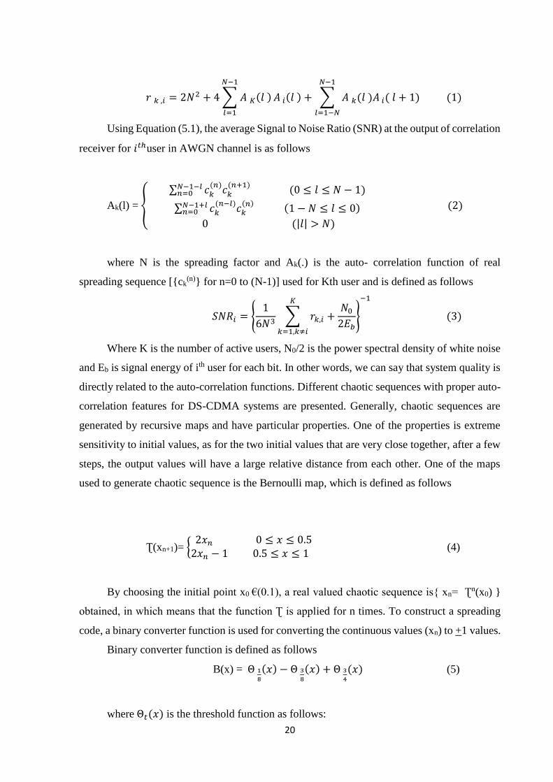
5.3.1 Chaotic Bernoulli Sequence with negative auto-correlation
In a DS-CDMA system, the average interference seen by user k from user i is obtained as
follows
20
𝑟 𝑘 ,𝑖 = 2𝑁2 + 4 ∑ 𝐴 𝐾(𝑙 )
𝑁−1
𝑙=1
𝐴 𝑖(𝑙 ) + ∑ 𝐴 𝑘(𝑙 )𝐴 𝑖( 𝑙 + 1)
𝑁−1
𝑙=1−𝑁
(1)
Using Equation (5.1), the average Signal to Noise Ratio (SNR) at the output of correlation
receiver for 𝑖𝑡ℎuser in AWGN channel is as follows
Ak(l) = {
∑ 𝑐𝑘(𝑛)
𝑐𝑘(𝑛+1)𝑁−1−𝑙
𝑛=0 (0 ≤ 𝑙 ≤ 𝑁 − 1)
∑ 𝑐𝑘(𝑛−𝑙)
𝑐𝑘(𝑛) 𝑁−1+𝑙
𝑛=0 (1 − 𝑁 ≤ 𝑙 ≤ 0)
0 (|𝑙| > 𝑁)
(2)
where N is the spreading factor and Ak(.) is the auto- correlation function of real
spreading sequence [{ck(n)} for n=0 to (N-1)] used for Kth user and is defined as follows
𝑆𝑁𝑅𝑖 = {1
6𝑁3∑ 𝑟𝑘,𝑖 +
𝑁0
2𝐸𝑏
𝐾
𝑘=1,𝑘≠𝑖
}
−1
(3)
Where K is the number of active users, N0/2 is the power spectral density of white noise
and Eb is signal energy of ith user for each bit. In other words, we can say that system quality is
directly related to the auto-correlation functions. Different chaotic sequences with proper auto-
correlation features for DS-CDMA systems are presented. Generally, chaotic sequences are
generated by recursive maps and have particular properties. One of the properties is extreme
sensitivity to initial values, as for the two initial values that are very close together, after a few
steps, the output values will have a large relative distance from each other. One of the maps
used to generate chaotic sequence is the Bernoulli map, which is defined as follows
Ʈ(xn+1)= {2𝑥𝑛 0 ≤ 𝑥 ≤ 0.5
2𝑥𝑛 − 1 0.5 ≤ 𝑥 ≤ 1 (4)
By choosing the initial point x0 €(0.1), a real valued chaotic sequence is{ xn= Ʈn(x0) }
obtained, in which means that the function Ʈ is applied for n times. To construct a spreading
code, a binary converter function is used for converting the continuous values (xn) to +1 values.
Binary converter function is defined as follows
B(x) = Θ 1
8
(𝑥) − Θ 3
8
(𝑥) + Θ 3
4
(𝑥) (5)
where Θ𝑡(𝑥) is the threshold function as follows:
21
Θ 𝑡 (𝑥) = {−1 (𝑥 < 𝑡)1 (𝑥 ≥ 𝑡)
(6)
It is also possible to use other binary functions. Average auto-correlation function for the
binary sequence is defined as follows
C(l)= E[𝐵(𝜏(𝑥))𝐵(𝜏𝑙(𝑥))] = ∫ B(τ(x))B(𝜏𝑙(𝑥))f(x)dx (7)
where f(.) is the Invariant Density Function for τ(x) and the integral is calculated over
interval [0,1]. It is shown for one-dimensional Bernoulli binary sequences, constructed by the
binary function B(.), that f (x) = 1 and E[B(τ1( x))] = 0. If all active users use the Bernoulli
sequences generated by this way, and the initial values of sequences are statistically
independent of each other, the average interference parameter (AIP) for each user can be written
as follows
𝑟 = 2𝑁2 + 4 ∑ (𝑁 − 𝑙)2𝑁−1𝑙=1 𝐶(𝑙) + 2 ∑ (𝑁 − 𝑙)(𝑁 − 𝑙 + 1)𝐶(𝑙)𝑐(𝑙 − 1)𝑁−1
𝑙=1 (8)
Normalized AIP is defined as R=limn-->∞ 𝑟
2𝑁2 and can be supposed as a criterion for
spreading code performance. It is clear that for a completely random sequence, C(l) is in form
of
𝐶(𝑙) = {
1 (𝑙 = 0)
𝜖 (𝑙 = 1)0 (𝑙 > 2)
(9)
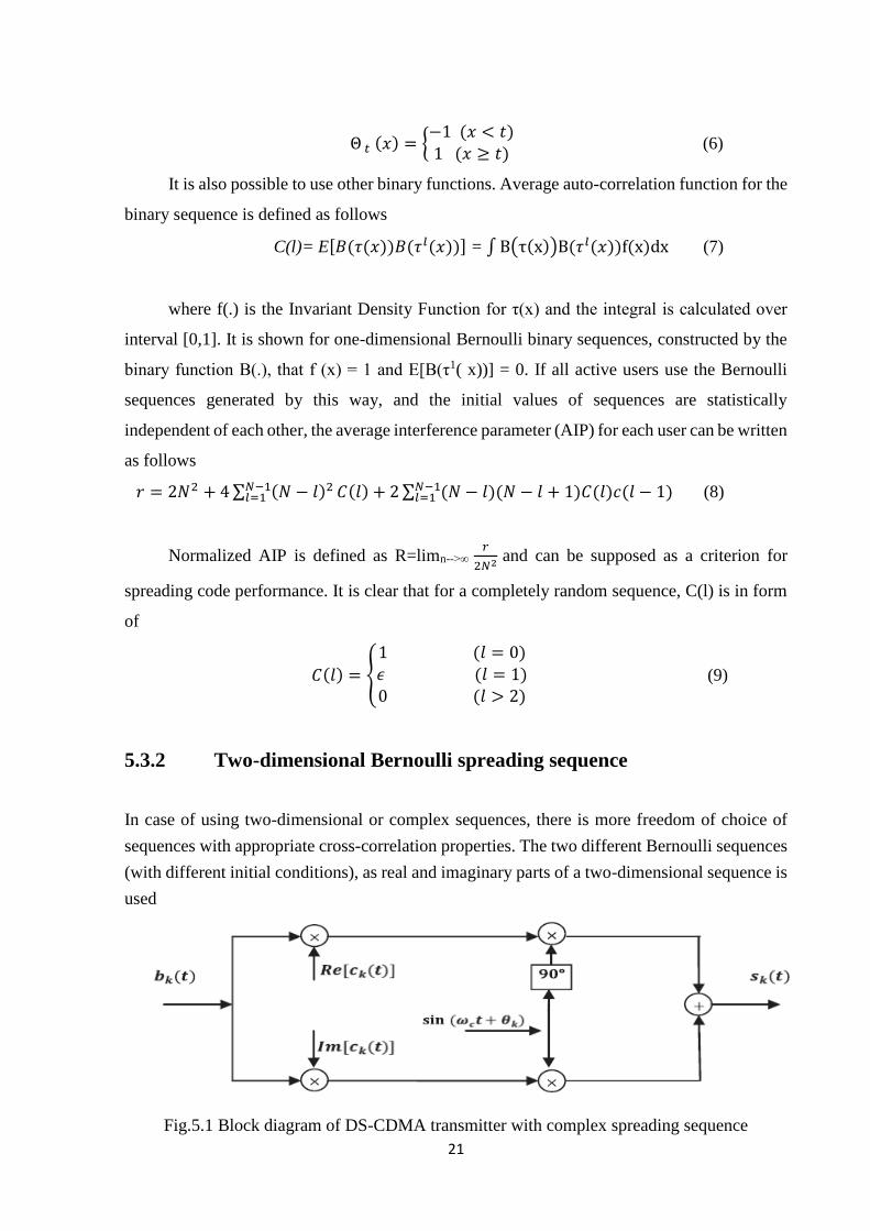
5.3.2 Two-dimensional Bernoulli spreading sequence
In case of using two-dimensional or complex sequences, there is more freedom of choice of
sequences with appropriate cross-correlation properties. The two different Bernoulli sequences
(with different initial conditions), as real and imaginary parts of a two-dimensional sequence is
used
Fig.5.1 Block diagram of DS-CDMA transmitter with complex spreading sequence

22
The two generated Bernoulli sequences by Bernoulli map with different initial
conditions x, y ϵ [0,1] and binary function B(.). Assume that the initial conditions x and y are
statistically independent. The complex binary sequence is defined as follows
{1
√2(𝐵(𝜏𝑛(𝑥)) + 𝑗𝐵(𝜏𝑛(𝑦)))}
0
𝑁−1
(10)
Factor of 1
√2 has been considered to have the same power as real sequence. Average
autocorrelation function is obtained as follows
𝐶(𝑙) = 1
2𝐸 [(𝐵(𝜏(𝑥)) + 𝑗𝐵(𝑦)))(𝐵(𝜏𝑙(𝑥)) − 𝑗𝐵(𝜏𝑙(𝑦)))]
= 1
2∫(𝐵(𝜏(𝑥)) + 𝑗𝐵(𝑦)))(𝐵(𝜏𝑙(𝑥)) − 𝑗𝐵(𝜏𝑙(𝑦)))𝑓(𝑥)𝑓(𝑦)𝑑𝑥𝑑𝑦 (11)
where f(.) is invariant density function for τ and the integral is calculated over interval
[0,1]. As said before, it is shown that f(x) = 1and 𝐸[(𝜏𝑙(𝑥))]=0 for one-dimensional Bernoulli
binary sequence constructed byB(.). Because of the deterministic nature of theBernoulli map
and the independence of x and y, it can be written
C(l) = 1
2(𝐸[𝐵(𝜏(𝑥))𝐵(𝜏𝑙(𝑥))] + [𝐵(𝜏(𝑦))𝐵(𝜏𝑙(𝑦))]) (12)
23
Chapter 6
Error Control Coding Techniques
6.1 Introduction
In information theory and coding theory, error detection and correction or error
control are techniques that enable reliable delivery of digital data over
unreliable communication channels. Many communication channels are subject to channel
noise, and thus errors may be introduced during transmission from the source to a receiver.
Error detection techniques allow detecting such errors, while error correction enables
reconstruction of the original data in many cases. The general idea for achieving error detection
and correction is to add some redundancy (i.e., some extra data) to a message, which receivers
can use to check consistency of the delivered message, and to recover data determined to be
corrupted. Error-detection and correction schemes can be either systematic or non-systematic:
In a systematic scheme, the transmitter sends the original data, and attaches a fixed number
of check bits (or parity data), which are derived from the data bits by some deterministic
algorithm. If only error detection is required, a receiver can simply apply the same algorithm to
the received data bits and compare its output with the received check bits; if the values do not
match, an error has occurred at some point during the transmission. In a system that uses a non-
systematic code, the original message is transformed into an encoded message that has at least
as many bits as the original message.
Good error control performance requires the scheme to be selected based on the
characteristics of the communication channel. Common channel models include memory-less
models where errors occur randomly and with a certain probability, and dynamic models where
errors occur primarily in bursts. Consequently, error-detecting and correcting codes can be
generally distinguished between random-error-detecting/ correcting and burst – error -

24
detecting/ correcting. Some codes can also be suitable for a mixture of random errors and burst
errors. The positions of the error control coding and decoding are shown in the transmission
model
Fig 6.1 Digital Communication Model
6.2 Error Control Coding Techniques
Error control coding aims at developing methods for coding to check the correctness of
the bit stream transmitted. The bit stream representation of a symbol is called the code word of
that symbol. Different error control mechanisms:
Linear Block Codes
Repetition Codes
Convolution Codes
Turbo Codes
6.2.1 Linear Block Codes
A code is linear if two codes are added using modulo-2 arithmetic produces a third
code word in the code. Consider a (n, k) linear block code. Here,
1. n represents the code word length
2. k is the number of message bit
3. n−k bits are error control bits or parity check bits generated from message using an
appropriate rule.

25
We may therefore represent the code word as:
𝐶𝑖 = { 𝑏𝑖 , 𝑖 = 0,1,2, … . . , 𝑛 − 𝑘 − 1
𝑚𝑖+𝑘−1 , 𝑖 = 𝑛 − 𝑘, 𝑛 − 𝑘 + 1, … 𝑛 − 1 (1)
The (n − k) parity bits are linear sums of the k message bits.
bi = p0im0 + p1im1 + · · · + pk−1,imk−1 (2)
where the coefficients are
𝑝𝑖𝑗 = {1, 𝑖𝑓 𝑏𝑖 𝑑𝑒𝑝𝑒𝑛𝑑𝑠 𝑜𝑛 𝑚𝑗
0, 𝑜𝑡ℎ𝑒𝑟𝑤𝑖𝑠𝑒 (3)
We define the 1-by-k message vector, or information vector, m, the 1-by-(n − k) parity
vector b, and the 1-by-n code vector c as follows:
m = [m0,m1, · · · ,mk−1]
b = [b0, b1, · · · , bn−k−1] (4)
n = [n0, n1, · · · , nn−1]
We may thus write simultaneous equations in matrix equation form as
b = Mp
where P is a k by n − k matrix.
c matrix can be expressed as a partitioned row vector in terms of the vectors m and b as
follows
c = [b : m]
c = m[P : Ik]
where Ik is a k-by-k identity matrix. Now, we define k-by-n generator matrix as
G = [P : Ik]
c = mG
Closure property of linear block codes: Consider a pair of code vectors ci and cj
corresponding to a pair of message vectors mi and mj respectively.
ci + cj = miG + mjG
= (mi + mj) G (5)
26
The modulo-2 sum of mi and mj represents a new message vector. Correspondingly, the
modulo-2 sum of ci and cj represents a new code vector. Suppose,
H = [In−k|PT ]
HGT = [In−k : PT] [𝑃𝑇
𝐼𝑛−𝑘]
= PT + PT
= 0
Post multiplying the basic equation c = mG with HT , then using the above result we get
cHT = mGHT
= 0
• A valid code word yields the above result.
• The matrix H is called the parity-check matrix of the code.
• The set of equations specified in the above equation are called parity-check-equations.
6.2.2 Repetition codes
This is the simplest of linear block codes. Here, a single message bit is encoded into a
block of n identical bits, producing an (n, 1) block code. This code allows variable amount of
redundancy. It has only two code words - all-zero codeword and all-one codeword.
Example, Consider a linear block code which is also a repetition code. Let k = 1 and
n = 5. From the analysis done in linear block codes
G = [1111: 1]
The parity check matrix takes the form
𝐻 = [
1 00 1
0 00 0
: 1: 1
0 00 0
1 00 1
: 1: 1
] (6)
6.2.3 Cyclic Codes
Cyclic property: Any cyclic shift of a code word in the code is also a code word. Cyclic
codes are well suited for error detection. Certain set of polynomials are chosen for this purpose.
Properties of polynomials:
1. Any polynomial B(x) can be divided by a divisor polynomial C(x) if B(x) is of higher
degree than C(x).

27
2. Any polynomial B(x) can be divided once by C(x) if both are of same degree.
3. Subtraction uses exclusive OR.
Cyclic Redundancy Check Codes:
Let M(x) be the original message polynomial of kth degree. The following steps are followed in
getting the code word in CRC.
1. Multiply the message polynomial M(x) by xn−k.
2. Divide xn−kM(x) by the generator polynomial G(x), obtaining the remainder B(x).
3. Add B(x) to xn−kM(x), obtaining the code polynomial C(x).
6.2.4 Convolution codes
Convolutional codes are commonly described using two parameters-
1. The code rate
2. The constraint length
The code rate, k/n, is expressed as a ratio of the number of bits into the convolutional
encoder (k) to the number of channel symbols output by the convolutional encoder (n) in a
given encoder cycle. The constraint length parameter, K, denotes the "length" of the
convolutional encoder, i.e. how many k-bit stages are available to feed the combinatorial logic
that produces the output symbols. Closely related to K is the parameter m, which indicates how
many encoder cycles an input bit is retained and used for encoding after it first appears at the
input to the convolutional encoder. The m parameter can be thought of as the memory length
of the encoder i.e. number of memory registers.
Constraint length, L = k (m-1) (7)
Convolutional codes are widely used as channel codes in practical communication
systems for error correction. The encoded bits depend on the current k input bits and a few past
input bits. The main decoding strategy for convolutional codes is based on the widely used
Viterbi algorithm. As a result of the wide acceptance of convolutional codes, there have been
several approaches to modify and extend this basic coding scheme. Trellis coded modulation
(TCM) and turbo codes are two such examples. In TCM, redundancy is added by combining
coding and modulation into a single operation. This is achieved without any reduction in data
rate or expansion in bandwidth as required by only error correcting coding schemes.
28
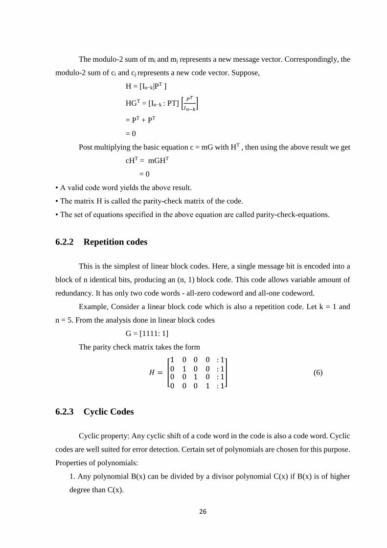
A simple convolutional encoder is shown in Fig.6.2. The information bits are fed in
small groups of k-bits at a time to a shift register. The output encoded bits are obtained by
modulo-2 addition (EXCLUSIVE-OR operation) of the input information bits and the contents
of the shift registers which are a few previous information bits.
Fig. 6.2 A convolutional encoder with k=1, n=2 and r=1/2
If the encoder generates a group of ‘n’ encoded bits per group of ‘k’ information bits,
the code rate R is commonly defined as R = k/n. In Fig.6.2, k = 1 and n = 2. The number, K of
elements in the shift register which decides for how many code words one information bit will
affect the encoder output, is known as the constraint length of the code. For the present example,
K = 3.
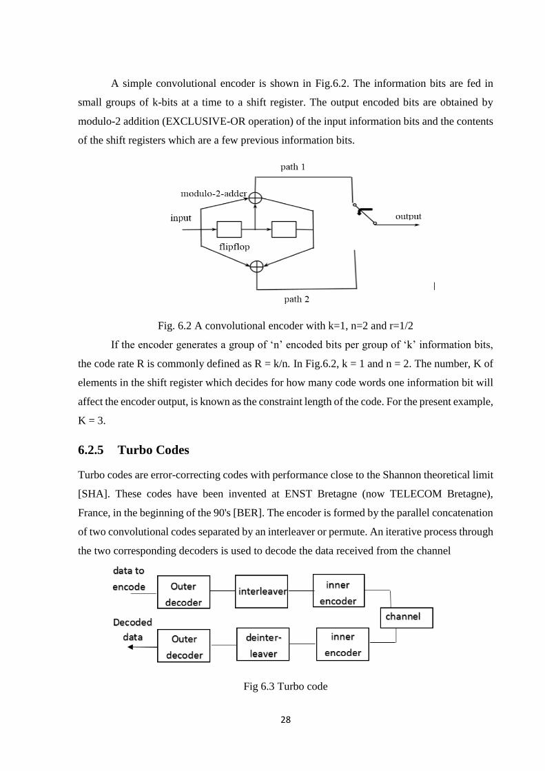
6.2.5 Turbo Codes
Turbo codes are error-correcting codes with performance close to the Shannon theoretical limit
[SHA]. These codes have been invented at ENST Bretagne (now TELECOM Bretagne),
France, in the beginning of the 90's [BER]. The encoder is formed by the parallel concatenation
of two convolutional codes separated by an interleaver or permute. An iterative process through
the two corresponding decoders is used to decode the data received from the channel
Fig 6.3 Turbo code
29
Each elementary decoder passes to the other soft (probabilistic) information about each bit of
the sequence to decode. This soft information, called extrinsic information, is updated at each
iteration.
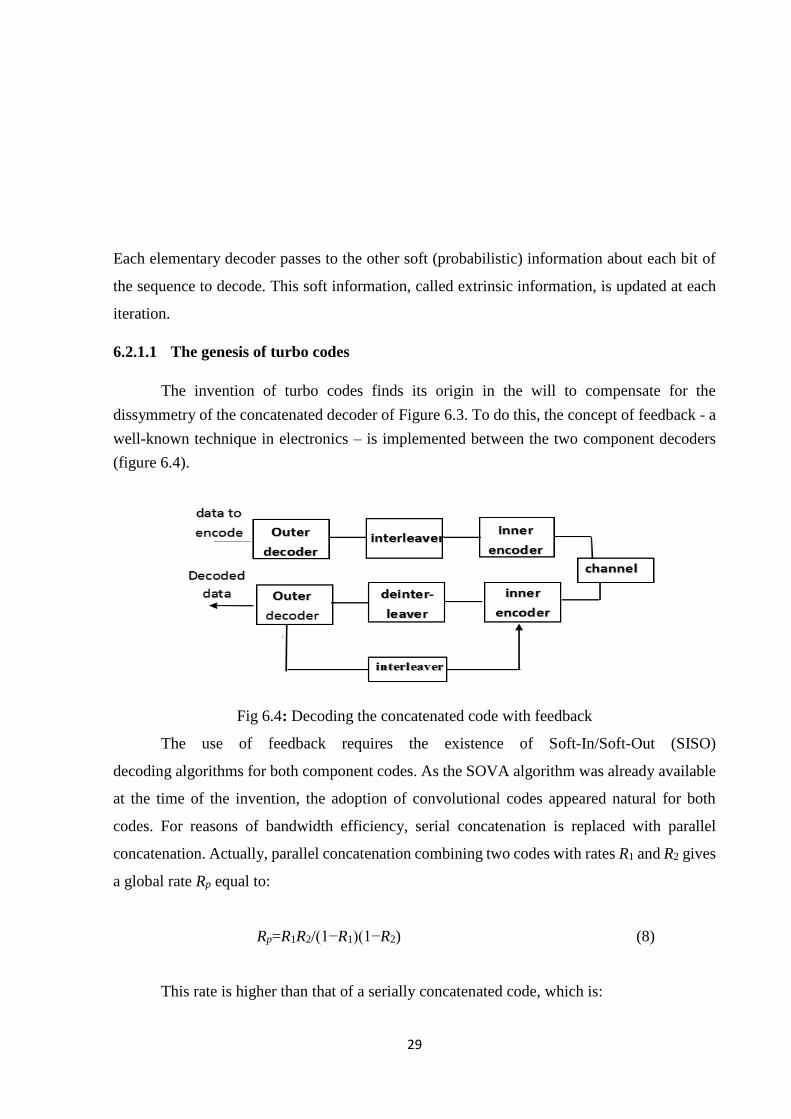
6.2.1.1 The genesis of turbo codes
The invention of turbo codes finds its origin in the will to compensate for the
dissymmetry of the concatenated decoder of Figure 6.3. To do this, the concept of feedback - a
well-known technique in electronics – is implemented between the two component decoders
(figure 6.4).
Fig 6.4: Decoding the concatenated code with feedback
The use of feedback requires the existence of Soft-In/Soft-Out (SISO)
decoding algorithms for both component codes. As the SOVA algorithm was already available
at the time of the invention, the adoption of convolutional codes appeared natural for both
codes. For reasons of bandwidth efficiency, serial concatenation is replaced with parallel
concatenation. Actually, parallel concatenation combining two codes with rates R1 and R2 gives
a global rate Rp equal to:
Rp=R1R2/(1−R1)(1−R2) (8)
This rate is higher than that of a serially concatenated code, which is:
30
Rs=R1*R2 (9)
for the same values of R1 and R2 , and the lower these rates, the larger the difference. Thus, with
the same performance of component codes, parallel concatenation offers a better global rate,
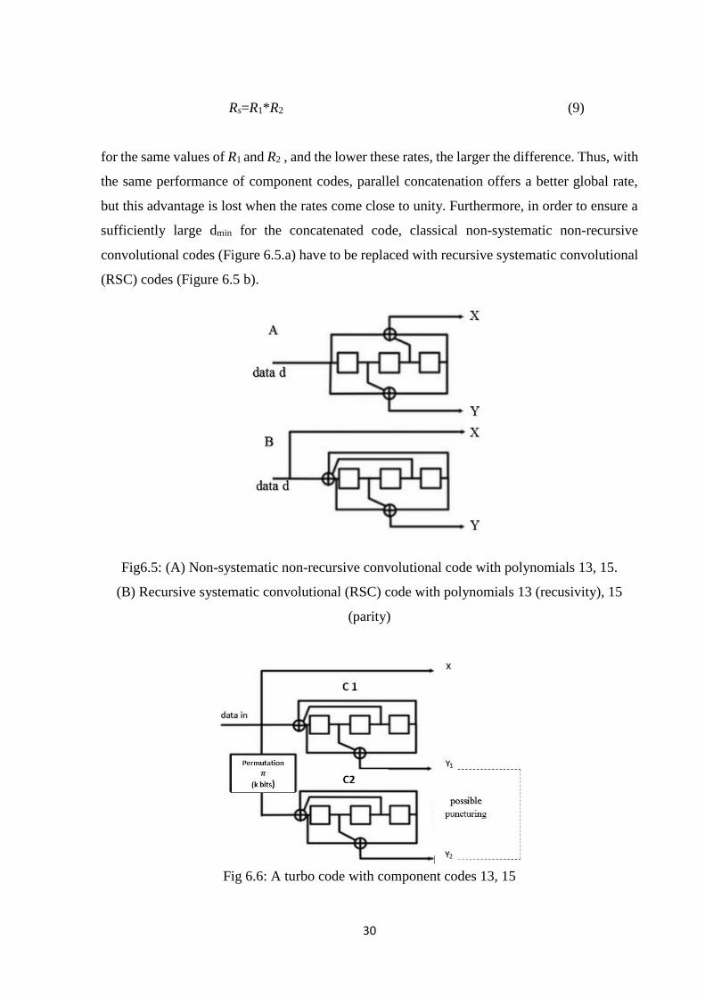
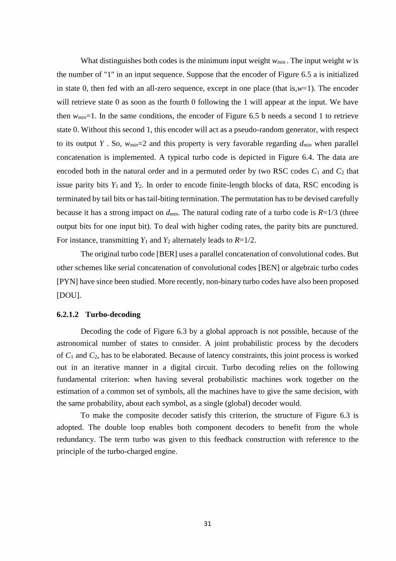
but this advantage is lost when the rates come close to unity. Furthermore, in order to ensure a
sufficiently large dmin for the concatenated code, classical non-systematic non-recursive
convolutional codes (Figure 6.5.a) have to be replaced with recursive systematic convolutional
(RSC) codes (Figure 6.5 b).
Fig6.5: (A) Non-systematic non-recursive convolutional code with polynomials 13, 15.
(B) Recursive systematic convolutional (RSC) code with polynomials 13 (recusivity), 15
(parity)
Fig 6.6: A turbo code with component codes 13, 15
31
What distinguishes both codes is the minimum input weight wmin . The input weight w is
the number of "1" in an input sequence. Suppose that the encoder of Figure 6.5 a is initialized
in state 0, then fed with an all-zero sequence, except in one place (that is,w=1). The encoder
will retrieve state 0 as soon as the fourth 0 following the 1 will appear at the input. We have
then wmin=1. In the same conditions, the encoder of Figure 6.5 b needs a second 1 to retrieve
state 0. Without this second 1, this encoder will act as a pseudo-random generator, with respect
to its output Y . So, wmin=2 and this property is very favorable regarding dmin when parallel
concatenation is implemented. A typical turbo code is depicted in Figure 6.4. The data are
encoded both in the natural order and in a permuted order by two RSC codes C1 and C2 that
issue parity bits Y1 and Y2. In order to encode finite-length blocks of data, RSC encoding is
terminated by tail bits or has tail-biting termination. The permutation has to be devised carefully
because it has a strong impact on dmin. The natural coding rate of a turbo code is R=1/3 (three
output bits for one input bit). To deal with higher coding rates, the parity bits are punctured.
For instance, transmitting Y1 and Y2 alternately leads to R=1/2.
The original turbo code [BER] uses a parallel concatenation of convolutional codes. But
other schemes like serial concatenation of convolutional codes [BEN] or algebraic turbo codes
[PYN] have since been studied. More recently, non-binary turbo codes have also been proposed
[DOU].
6.2.1.2 Turbo-decoding
Decoding the code of Figure 6.3 by a global approach is not possible, because of the
astronomical number of states to consider. A joint probabilistic process by the decoders
of C1 and C2, has to be elaborated. Because of latency constraints, this joint process is worked
out in an iterative manner in a digital circuit. Turbo decoding relies on the following
fundamental criterion: when having several probabilistic machines work together on the
estimation of a common set of symbols, all the machines have to give the same decision, with
the same probability, about each symbol, as a single (global) decoder would.
To make the composite decoder satisfy this criterion, the structure of Figure 6.3 is
adopted. The double loop enables both component decoders to benefit from the whole
redundancy. The term turbo was given to this feedback construction with reference to the
principle of the turbo-charged engine.
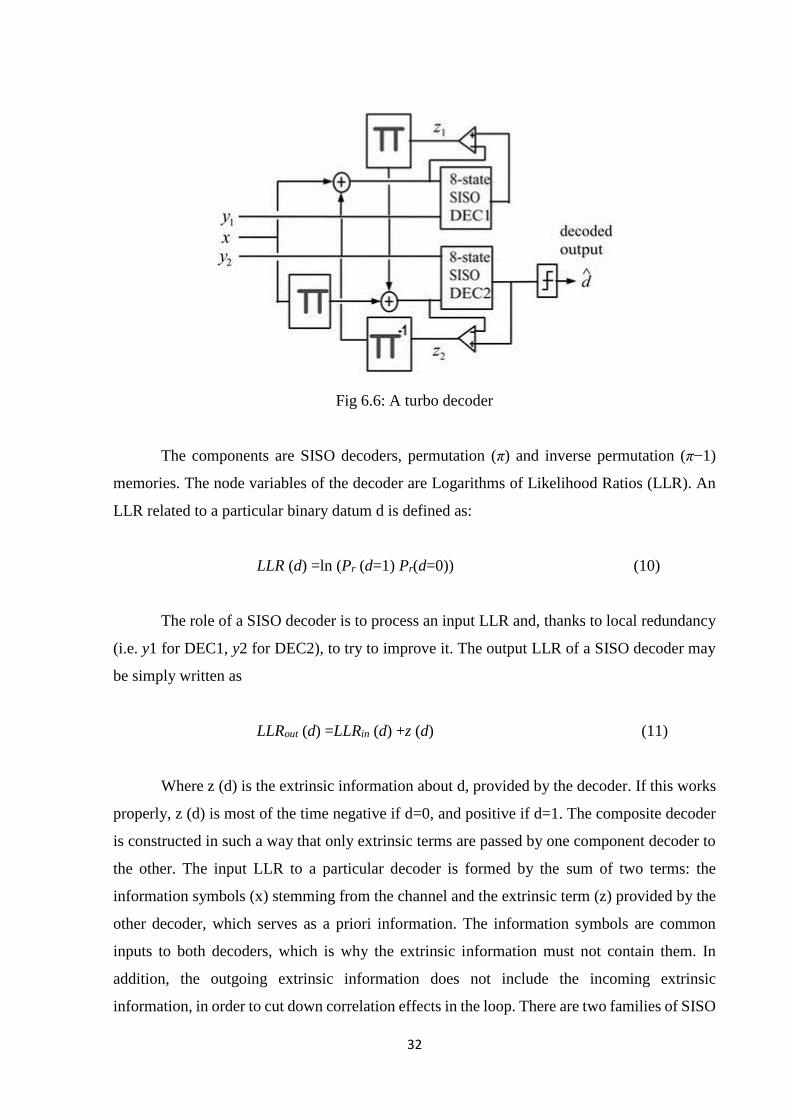
32
Fig 6.6: A turbo decoder
The components are SISO decoders, permutation (π) and inverse permutation (π−1)
memories. The node variables of the decoder are Logarithms of Likelihood Ratios (LLR). An
LLR related to a particular binary datum d is defined as:
LLR (d) =ln (Pr (d=1) Pr(d=0)) (10)
The role of a SISO decoder is to process an input LLR and, thanks to local redundancy
(i.e. y1 for DEC1, y2 for DEC2), to try to improve it. The output LLR of a SISO decoder may
be simply written as
LLRout (d) =LLRin (d) +z (d) (11)
Where z (d) is the extrinsic information about d, provided by the decoder. If this works
properly, z (d) is most of the time negative if d=0, and positive if d=1. The composite decoder
is constructed in such a way that only extrinsic terms are passed by one component decoder to
the other. The input LLR to a particular decoder is formed by the sum of two terms: the
information symbols (x) stemming from the channel and the extrinsic term (z) provided by the
other decoder, which serves as a priori information. The information symbols are common
inputs to both decoders, which is why the extrinsic information must not contain them. In
addition, the outgoing extrinsic information does not include the incoming extrinsic
information, in order to cut down correlation effects in the loop. There are two families of SISO
33
algorithms, those based on the SOVA [BAT] [HAG], the others based on the MAP (also called
BCJR or APP) algorithm [BAH] or its simplified versions. Turbo decoding is not optimal. This
is because an iterative process has obviously to begin, during the first half-iteration, with only
a part of the redundant information available (either y1 or y2). Fortunately, loss due to sub-
optimality is small (less than 0.5dB).
34
Chapter 7
Multiple Access Interference
7.1 Motivation for Multiple Access Interference Characterization
The ever increasing demand for world-wide multiple access wireless communications
drives the need to maximize the current system capability and transmission capacity. Many
current systems employ direct-sequence spread-spectrum (DSSS) techniques to enable multiple
access capability. A clearer understanding of how multiple users effect overall system
performance, through characterization of the multiple access interference (MAI), enables more
efficient use of current systems and better designs for future systems. Although a large body of
research exists on how MAI impacts direct-sequence spread-spectrum multiple access
(DS/SSMA) performance, most of this work relies on analytical approximations. Additionally,
there are numerous factors that can affect MAI contributions in a system between workload and
environment (e.g., number of simultaneous transmitters, type of multiple access coding, and
code length). Current approximations only account for a limited number of these factors and
can require extensive recalculation when factors are changed or added. The state of existing
research into MAI in DS/SSMA systems leaves open a need for a representative system model
that is easily modified to account for different factors.
This need lends itself to characterization of MAI in DS/SSMA systems through
simulation. Simulation of DS/SSMA system performance provides two main benefits. First,
simulation allows for rapid testing of the effects that numerous factors can have on system
performance and such factors can be changed or others added relatively easily. Second,
simulation enables verification of future approximations through a vehicle that more closely

35
represents the actual, physical communication system.
7.2 Gaussian Approximation of MAI
In one class of algorithm, the MAI term is approximated by a Gaussian random variable.
From (2) the MAI term consists of the sum K-1 discrete binary random variable. From the
center limit theorem, as the number of user k increases, the distribution of the MAI term
approaches that of a Gaussian. Each single user binary probability distribution consists of the
coded bit probability 𝑃𝑟(𝑑𝑡(𝑘)
) = 1 and 𝑃𝑟(𝑑𝑡(𝑘)
) = −1 , k ε {1,….,k} . The mean variance of
these binary distribution for the kth user, k ε {1,….,k} are calculated as
𝑚𝑡(𝑘)
= 𝑃𝑟(𝑑𝑡(𝑘)
= 1) − 𝑃𝑟(𝑑𝑡(𝑘)
= −1) (1)
𝑣𝑡2 (𝑘)
= 1 − [ 𝑃𝑟(𝑑𝑡(𝑘)
= 1) − 𝑃𝑟(𝑑𝑡(𝑘)
= −1)]2 (2)
The addition of these binary distribution results in the MAI term ρ ∑ 𝑑𝑡(𝑖)𝐾
𝑖=1 for the
kth user having Gaussian distribution with mean and variance:
µ𝑡 ,𝑀𝐴𝐼(𝑘)
= ρ ∑ [𝑃𝑟(𝑑𝑡(𝑘)
= 1) − 𝑃𝑟(𝑑𝑡(𝑘)
= −1)]𝐾𝑖=1
= ρ ∑ 𝑚𝑡(𝑖)𝐾
𝑖=1𝑖≠𝑚
(3)
𝜎𝑡,𝑀𝐴𝐼2(𝑘)
= 𝜌2 ∑(1 − [𝑃𝑟(𝑑𝑡(𝑘)
= 1) − 𝑃𝑟(𝑑𝑡(𝑘)
= −1)]2)
𝐾
𝑖=1𝑖≠𝑘
= 𝜌2 ∑ 𝑣𝑡2 (𝑘)𝐾
𝑖=1𝑖≠𝑚
(4)
36
The probability distribution ƥ (𝑟𝑡(𝑘)
| 𝑑𝑡(𝑘)
= 𝑑), d ∈ {-1, 1} for the kth user is derived as a
Gaussian random variable with mean µ𝑡(𝑘)
= 𝑑 + µ𝑡,𝑀𝐴𝐼(𝑘)
and variance 𝜎𝑡2(𝑘)
= 𝜎2 + 𝜎𝑡,𝑀𝐴𝐼2 (𝑘)
7.3 Discrete Analysis of MAI
The continuous Gaussian approximation of the MAI receiver becomes accurate when the
number of users become large. Thus, a different approach is needed to determine the probability
distribution of the MAI when the number of user is small. the MAI term ρ ∑ 𝑑𝑡(𝑖)𝐾
𝑖=1𝑖≠𝑚
for user k
is discrete quantity hat can only take on K different values since each coded bit 𝑑𝑡(𝑖)
can only
take on values {-1,1} .As a result , the MAI term can be represented as a random variable with
a binomial distribution .this probability distribution is obtained for user k by convolving the
other k-1 sets of bit probability to produce the set of probability values
{𝑃𝑡,𝑚(𝑘)
}={𝑃𝑟 (∑ 𝑑𝑡(𝑖)𝐾
𝑖=1𝑖≠𝑚
= 𝑚)}, where m ∈{-(K-1),-(K-3) …,(K-3),(K-1)}. The value of the
metric is determined by convolving the distribution of the MAI and the Gaussian noise. The
Convolution of these two distribution results in
ƥ (𝑟𝑡(𝑘)
| 𝑑𝑡(𝑘)
= 𝑑) =1
√2ᴨ𝜎2∑ 𝑒𝑥𝑝 [−
(𝑟𝑡(𝑘)
−𝑑−𝑝𝑚)2
2𝜎2]𝑚 × 𝑃𝑡,𝑚′
(𝑘) (5)
where m’ ∈ {-(k-1),-(k-3)… (k-3), (k-1)} and d ∈ {-1, 1}.

37
Chapter 8
Results
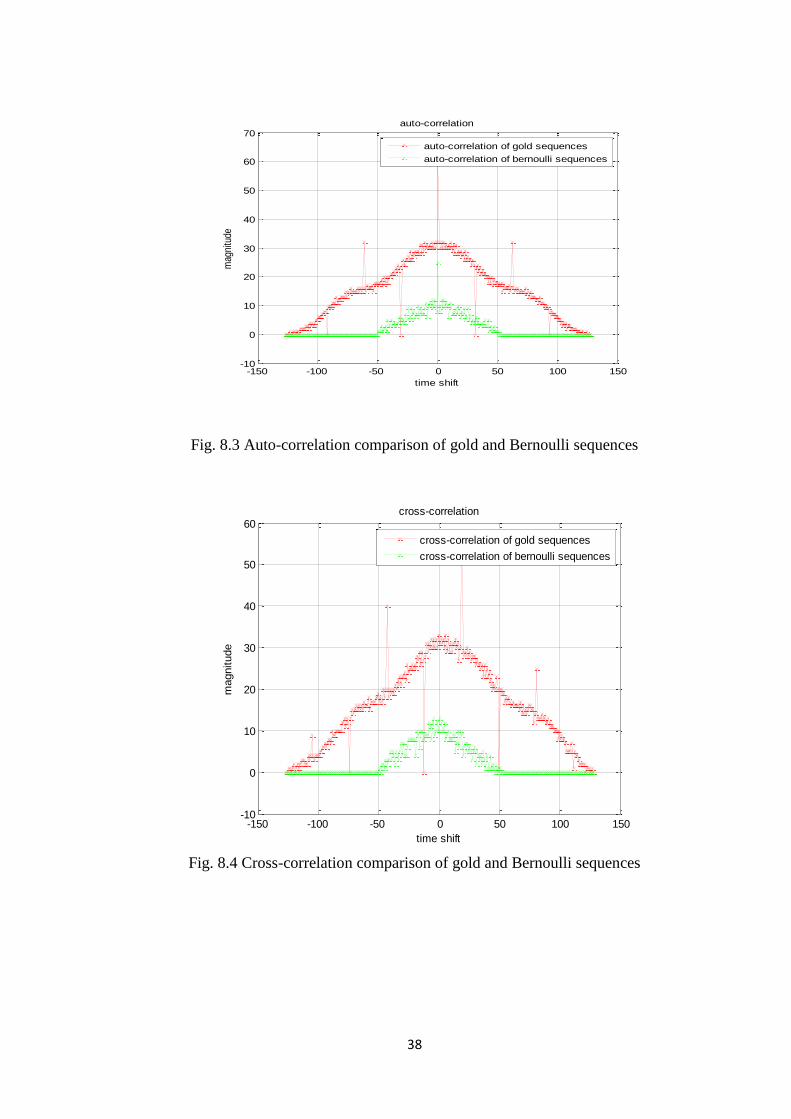
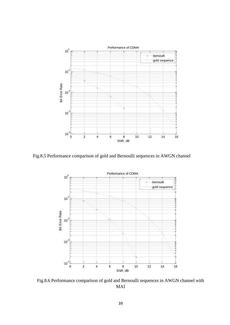
DS-CDMA system was studied with two types of spreading sequences. Conventional
gold sequence performance was compared with new chaotic sequences generated using
Bernoulli map. It is observed that the performance of chaotic sequences is better than Gold
sequences. Correlation properties o DS-CDMA system was studied under two channel
environments. AWGN channel and Rayleigh fading channel. MAI effect on performance is
also studied and corresponding BER is plotted. Also, performance of DS-CDMA system was
studied for different number of users. It is observed that the BER decreases with increase in
number of users.
Fig.8.1 Auto- correlation magnitude vs time Fig.8.2 cross-correction magnitude vs time
-1500 -1000 -500 0 500 1000 1500-5
0
5
10
15
20
25
30
time shift
magnitude
auto-correlation
auto-correlation of bernoulli sequences
-1500 -1000 -500 0 500 1000 1500-2
0
2
4
6
8
10
12
14
16
time shift
magnitude
cross-correlation
cross-correlation of bernoulli sequences
38
Fig. 8.3 Auto-correlation comparison of gold and Bernoulli sequences
Fig. 8.4 Cross-correlation comparison of gold and Bernoulli sequences
-150 -100 -50 0 50 100 150-10
0
10
20
30
40
50
60
70
time shift
mag
nitu
de
auto-correlation
auto-correlation of gold sequences
auto-correlation of bernoulli sequences
-150 -100 -50 0 50 100 150-10
0
10
20
30
40
50
60
time shift
magnitude
cross-correlation
cross-correlation of gold sequences
cross-correlation of bernoulli sequences
39
Fig.8.5 Performance comparison of gold and Bernoulli sequences in AWGN channel
Fig.8.6 Performance comparison of gold and Bernoulli sequences in AWGN channel with
MAI
0 2 4 6 8 10 12 14 1610
-4
10-3
10-2
10-1
100
SNR, dB
Bit E
rror
Rate
Performance of CDMA
bernoulli
gold sequence
0 2 4 6 8 10 12 14 1610
-4
10-3
10-2
10-1
100
SNR, dB
Bit E
rror
Rate
Performance of CDMA
bernoulli
gold sequence

40
Fig.8.7 Performance comparison of gold and Bernoulli sequences in Rayleigh fading channel
Fig.8.8 Comparison of gold and Bernoulli sequences with and without turbo coding
0 5 10 15 20 2510
-3
10-2
10-1
100
SNR, dB
Bit E
rror
Rate
Performance of CDMA
bernoulli
gold sequence
0 2 4 6 8 10 12 14 1610
-3
10-2
10-1
100
SNR, dB
Bit E
rror
Rate
Performance of CDMA
without turbo coding gold seq.
with turbo coding gold seq.
without turbo coding bernoulli seq.
with turbo coding bernoulli seq.

41
Fig.8.9 Turbo code Performance for different number of iterations in AWGN channel without
MAI
Fig.8.10 Turbo code Performance for different number of iterations in AWGN channel with
MAI
0 2 4 6 8 10 1210
-4
10-3
10-2
10-1
100
SNR, dB
Bit E
rror
Rate
Performance of CDMA
without turbo coding
with turbo coding itr=1
with turbo coding itr=2
with turbo coding itr=3
with turbo coding itr=5
with turbo coding itr=10
0 1 2 3 4 5 6 7 8 9 1010
-4
10-3
10-2
10-1
100
SNR, dB
Bit E
rror
Rate
Performance of CDMA
without turbo coding
with turbo coding itr=1
with turbo coding itr=2
with turbo coding itr=3
with turbo coding itr=5
with turbo coding itr=10

42
Fig.8.11 Turbo code performance for different number of iterations in Rayleigh fading
channel
Fig.8.12 BER vs number of users for Gold and Bernoulli sequences
0 2 4 6 8 10 12 1410
-4
10-3
10-2
10-1
100
SNR, dB
Bit E
rror
Rate
Performance of CDMA
without turbo coding
with turbo coding itr=1
with turbo coding itr=2
with turbo coding itr=3
with turbo coding itr=5
with turbo coding itr=10
43
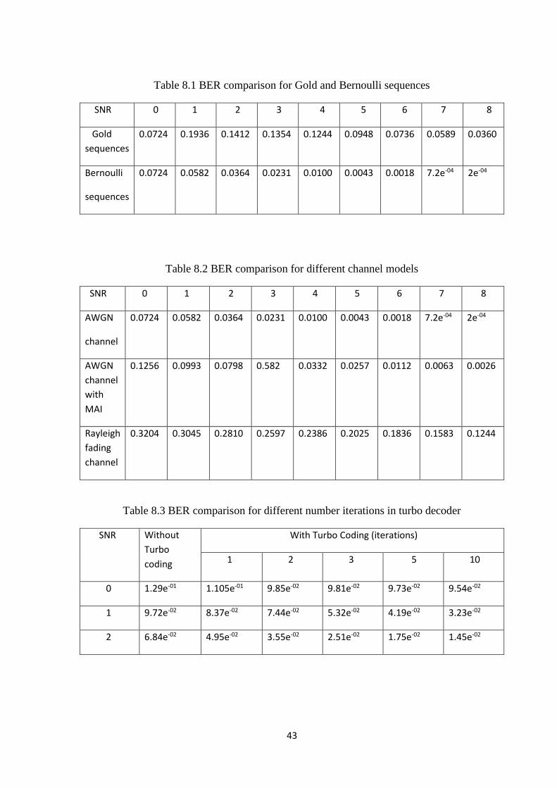
Table 8.1 BER comparison for Gold and Bernoulli sequences
SNR 0 1 2 3 4 5 6 7 8
Gold
sequences
0.0724 0.1936 0.1412 0.1354 0.1244 0.0948 0.0736 0.0589 0.0360
Bernoulli
sequences
0.0724 0.0582 0.0364 0.0231 0.0100 0.0043 0.0018 7.2e-04 2e-04
Table 8.2 BER comparison for different channel models
SNR 0 1 2 3 4 5 6 7 8
AWGN
channel
0.0724 0.0582 0.0364 0.0231 0.0100 0.0043 0.0018 7.2e-04 2e-04
AWGN
channel
with
MAI
0.1256 0.0993 0.0798 0.582 0.0332 0.0257 0.0112 0.0063 0.0026
Rayleigh
fading
channel
0.3204 0.3045 0.2810 0.2597 0.2386 0.2025 0.1836 0.1583 0.1244
Table 8.3 BER comparison for different number iterations in turbo decoder
SNR Without
Turbo
coding
With Turbo Coding (iterations)
1 2 3 5 10
0 1.29e-01 1.105e-01 9.85e-02 9.81e-02 9.73e-02 9.54e-02
1 9.72e-02 8.37e-02 7.44e-02 5.32e-02 4.19e-02 3.23e-02
2 6.84e-02 4.95e-02 3.55e-02 2.51e-02 1.75e-02 1.45e-02

44
Chapter 9
Conclusion
In this project, two-dimensional Bernoulli chaotic sequences are introduced. They can
be used to generate complex spreading sequences for utilizing in DS-CDMA system. Amongst
the complex sequences it is much easier to choose a proper set of sequences for multi-user DS-
CDMA systems. Complex two-dimensional sequence is obtained by combining two one-
dimensional Bernoulli sequences with different initial conditions. Employing the new
sequences can improve the performance of DS-CDMA systems compared with the
conventional spreading codes as well as similar complex spreading codes, such as the gold
codes. The performance improvement is due to the following reasons
the proper auto-correlation function
more freedom of choice of appropriate codes among complex codes
which results in decrease of BER and increase in cellular capacity.
It is also concluded that turbo codes provide better error performance and sufficient
coding gain as compared with system without turbo coding. Increase in number of iterations
improves BER performance but computation time increases too. Turbo coding shows
significant advantage in case of channel with MAI consideration as well as for fading channel.

45
Literature cited
[1] Claude, B., & Alan, G.. “Near Optimum Error Correcting Coding and Decoding: Turbo
Codes”, IEEE Transactions on Communications, Vol. 44, No. 10, 1996.
[2] CongL. & Shaoqian L., “Chaotic spreading sequences with multiple access performance better
than random sequences”. IEEE Transactions on Circuits and Systems: Fundamental Theory and
Applications, 47, 3, 2000.
[3] Kurian A. P., Puthusserypady S., & Htut S. M., “Performance enhancement of DS/CDMA
system using chaotic complex spreading sequence”. IEEE Transactions on Wireless
Communications, 4, 3, 2005.
[4] Mazzini G., Setti G., & Rovatti R., “Chaotic complex spreading sequences for asynchronous
DS-CDMA—Part I: System modeling and results”. IEEE Transactions on Circuits and SystemsPart
I, 44, 937–947. 1997.
[5] Rahnama N., & Talebi S., “Performance comparison of chaotic spreading sequences generated
by two different classes of chaotic systems in a chaos-based direct sequence-code division multiple
access system”. IET Communications, 7(10), 1024–1031, 2013.
[6] Rovatti R., Mazzini G., &Setti G., “On the ultimate limits of chaos-based asynchronous DS-
CDMA-I: Basic definitions and results”. IEEE Transactions on Circuits and Systems, 51, 1336–
1347, 2004.
[7] Stienstra D. & Khandani A. K., “Iterative multi-user turbo-code receiver for ds-cdma”. 2005
[8] Todd K. Moon, “Error Correction Coding Mathematical Methods and Algorithms.”
[9] Tsuneda A., “Design of binary sequences with tunable exponential autocorrelations and run
statistics based on one-dimensional chaotic maps”. IEEE Transactions on Circuits and systems-I,
52 (2), 454–462, 2005.
[10] Tsuneda A. & Miyazaki Y. “Performance evaluation of LFSR-based spreading sequences
with negative auto-correlation designed by chaos theory of modulo-2 added sequences”. European
Conference on Circuit Theory and Design, ECCTD 2009, Antalya (pp.141–
144).doi:10.1109/ECCTD.2009.5274956, 2009.
[11] Tsuneda A. & Miyazaki, Y., “Binary spreading sequences with negative auto-correlation
based on chaos theory and gold sequences for application to asynchronous DS/CDMA
46
communications”. IEICE Transactions on Fundamentals of Electronics, Communications and
Computer Sciences, E93.A(11), 2307–2311, 2010.
[12] G.V.Reddy, “Performance Evaluation of different DS-CDMA receivers using chaotic
sequences”, ethesis.nitrkl.ac.in/18/, 2007.
[13] Stavroulakis P. “Chaos applications in telecommunications”. Hoboken, NJ: CRC Press.
ISBN-13: 978-0849338328, 2005.

47
Acknowledgements
We consider it as a great privilege to express our deep gratitude to many respected
personalities who guided, inspired and helped us in the successful completion of our project.
We would like to express our deepest gratitude to our guide Dr. S Anuradha, Assistant
Professor, Department of Electronics and Communication Engineering, National Institute of
Technology, Warangal, for her constant supervision, guidance, suggestions and invaluable
encouragement during this project.
We are grateful to Dr. T Kishore Kumar, Head of Department of Electronics and
Communication Engineering, National Institute of Technology, Warangal, for his moral support
to carry out this project.
We are very thankful to Sri. M V Raghunadh and Dr. P Srihari Rao, Project
Coordinators for their continuous support throughout the year.
We are very thankful to Project Evaluation Committee, for their strenuous efforts to
evaluate our projects.
We wish to thank all the staff members in the department for their kind cooperation and
support given throughout our project work. We are also thankful to all of my friends who have
given valuable suggestions and help in all stages of the development of the project.
Snehal Chipade (114254)
Piyush Meshram (114243)