report -...
TRANSCRIPT

REPORT 2 TON PER MONTH
PREGABALIN MANUFACTURE
BIZOTIC LIFESCIENCE PVT. LTD. NEW KHARECHIYA, MORBI, GUJARAT
________________________________________
LACIMEHC PROTECH PVT LTD
Address: 214-216, Vinayak Complex Contact: [email protected] Manjalpur, Vadodara Tel Ph: +91 7567311166
Website: www.lacimehc.com +91 8140614866

REPORT: 2 TON PER MONTH PREGABALIN MANUFACTURE
1 | C L I E N T : B I Z O T I C L I F E S C I E N C E P V T . L T D . , M O R B I , G U J A R A T
INDEX
SL.
NO.
CONTENT
PAGE
NO.
1 INTRODUCTION 2
2 PROCESS DESCRIPTION 3
3 MATERIAL BALANCE 10
4 RAW MATERIAL REQUIREMENT 13
5 LIST OF PROPOSED EQUIPMENT AND UTILITIES 14
6 EQUIPMENT CAPACITY 16
7 WATER BALANCE 17
8 WATER CHART 18
9 AIR DETAILS 19
10 DETAILS OF PROPOSED EFFLUENT TREATMENT PLANT 20
11 BLOCK DIAGRAM OF ETP SECTION 21
12 BLOCK DIAGRAM OF PROCESS 22
13 LAYOUT DRAWING 23
14 PRODUCTION PLAN LAYOUT 24
REPORT: 2 TON PER MONTH PREGABALIN MANUFACTURE
2 | C L I E N T : B I Z O T I C L I F E S C I E N C E P V T . L T D . , M O R B I , G U J A R A T
INTRODUCTION
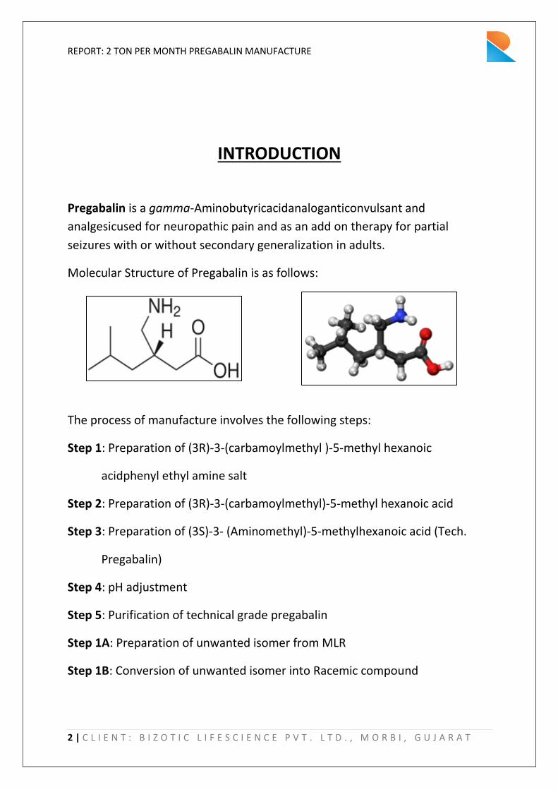
Pregabalin is a gamma-Aminobutyricacidanaloganticonvulsant and
analgesicused for neuropathic pain and as an add on therapy for partial
seizures with or without secondary generalization in adults.
Molecular Structure of Pregabalin is as follows:
The process of manufacture involves the following steps:
Step 1: Preparation of (3R)-3-(carbamoylmethyl )-5-methyl hexanoic
acidphenyl ethyl amine salt
Step 2: Preparation of (3R)-3-(carbamoylmethyl)-5-methyl hexanoic acid
Step 3: Preparation of (3S)-3- (Aminomethyl)-5-methylhexanoic acid (Tech.
Pregabalin)
Step 4: pH adjustment
Step 5: Purification of technical grade pregabalin
Step 1A: Preparation of unwanted isomer from MLR
Step 1B: Conversion of unwanted isomer into Racemic compound

REPORT: 2 TON PER MONTH PREGABALIN MANUFACTURE
3 | C L I E N T : B I Z O T I C L I F E S C I E N C E P V T . L T D . , M O R B I , G U J A R A T
PROCESS DESCRIPTION
STAGE 1:
Procedure :
1. Charge Chloroform into reactor.
2. Charge Methanolinto reactor.
3. Charge (±)-3-(carbamoymethyl)-5-methyl hexanoic acid into reactor.
4. Raise the temperature of the reaction mass to 50 - ⁰C.
5. Add R-(+)-1-phenyl ethyl mine to the above slurry slowly at 50 - ⁰C.
6. Maintain for 15 min at 50 - ⁰C.
7. Again add R-(+)-1-phenyl ethyl mine to reaction mass at 50 - ⁰C.
8. Check the mass, it should be clear.
9. Maintain mass for 30 min at 50 - ⁰C.
10. Stop heating and charge (3R)-(-)-3-(carbamoylmethyl)-5-methyl-hexanoic acid as a seeding
for crystallization under stirring.
11. Cool the mass slowly to 30- ⁰C.
12. Maintain under stirring for 30 min at 30 - ⁰C.
13. Centrifuge the material and wash with chloroform.
14. The wet cake is ready for next stage.

REPORT: 2 TON PER MONTH PREGABALIN MANUFACTURE
4 | C L I E N T : B I Z O T I C L I F E S C I E N C E P V T . L T D . , M O R B I , G U J A R A T
STAGE 2:
Procedure:
1. Charge water (lot-1) into reactor.
2. Charge (3R)-3-(Carbamoylmethyl)-5-methylhexanoic acidphenylethylamine salt into reactor.
3. Cool the reactio ass up to to ⁰C.
4. Adjust the mass pH to 10-11 using sodium hydroxide solution. (Dissolve sodium hydroxide in
water(Lot-2))
5. Maintain the mass for 30 min under stirring.
6. Solution should be clear.
7. Charge chloroform (lot-1) into the reactor.
8. Maintain reaction for 30 min under stirring.
9. Settle the mass for 30 min.
10. Separate the lower chloroform layer.
11. Again charge chloroform (lot-2) into the reactor.
12. Maintain reaction mass for 30 min under stirring.
13. Settle the mass for 30 min.
14. Separate the lower chloroform layer.
15. Slowly adjust the pH to 2-3 using con. HCl.
16. Maintain the mass at 10-1 ⁰C for hr.
17. Centrifuge the material.
18. Wash the material with water (lot-3).
19. The wet cake is ready for next stage.

REPORT: 2 TON PER MONTH PREGABALIN MANUFACTURE
5 | C L I E N T : B I Z O T I C L I F E S C I E N C E P V T . L T D . , M O R B I , G U J A R A T
STAGE 3:
Procedure:
1. Charge water lot-1 into the reactor.
2. Charge NaOH lot-1 into the reactor.
3. Cool the ass to to ⁰C.
4. Add chlori e gas i to the reactor slowly at to ⁰C gas purgi g .
5. After addition of gas, transfer the sodium hypochlorite solution in to the Buffer Tank.
6. Then in the same reactor, charge water lot-2 into the reactor.
7. Charge NaOH lot-2 in reactor.
8. Cool the mass to 0- ⁰C.
9. Charge (3R)-3-(Carbamoylmethyl)-5-methylhexanoic acid into reactor from Stage 2.
10. Maintain the mass for 30 min.
11. Add sodium hypochlorite solution slowly at 0 to 15 ⁰C (exothermic reaction)
12. After addition maintain mass for hr at to ⁰C.
13. Slowly raise the temperature to 50 - ⁰C.
14. Maintain the reaction mass at 50 - ⁰C for -45 min.
15. Cool the mass to 30 - ⁰C.
16. Filter the mass through hiflow bed (sparkler filter).
NaOH

REPORT: 2 TON PER MONTH PREGABALIN MANUFACTURE
6 | C L I E N T : B I Z O T I C L I F E S C I E N C E P V T . L T D . , M O R B I , G U J A R A T
STAGE 4:
1. Now, put the mass into a Mixing Vessel to adjust the mass pH 3.5 by adding 50 % H2SO4
solution at 30- ⁰C.
2. Adjust the mass pH 7-7.5 using 50 % NaOH solution at 25- ⁰C.
3. Maintain the mass at 20- ⁰C for hr.
4. Centrifuge the material.
REPORT: 2 TON PER MONTH PREGABALIN MANUFACTURE
7 | C L I E N T : B I Z O T I C L I F E S C I E N C E P V T . L T D . , M O R B I , G U J A R A T
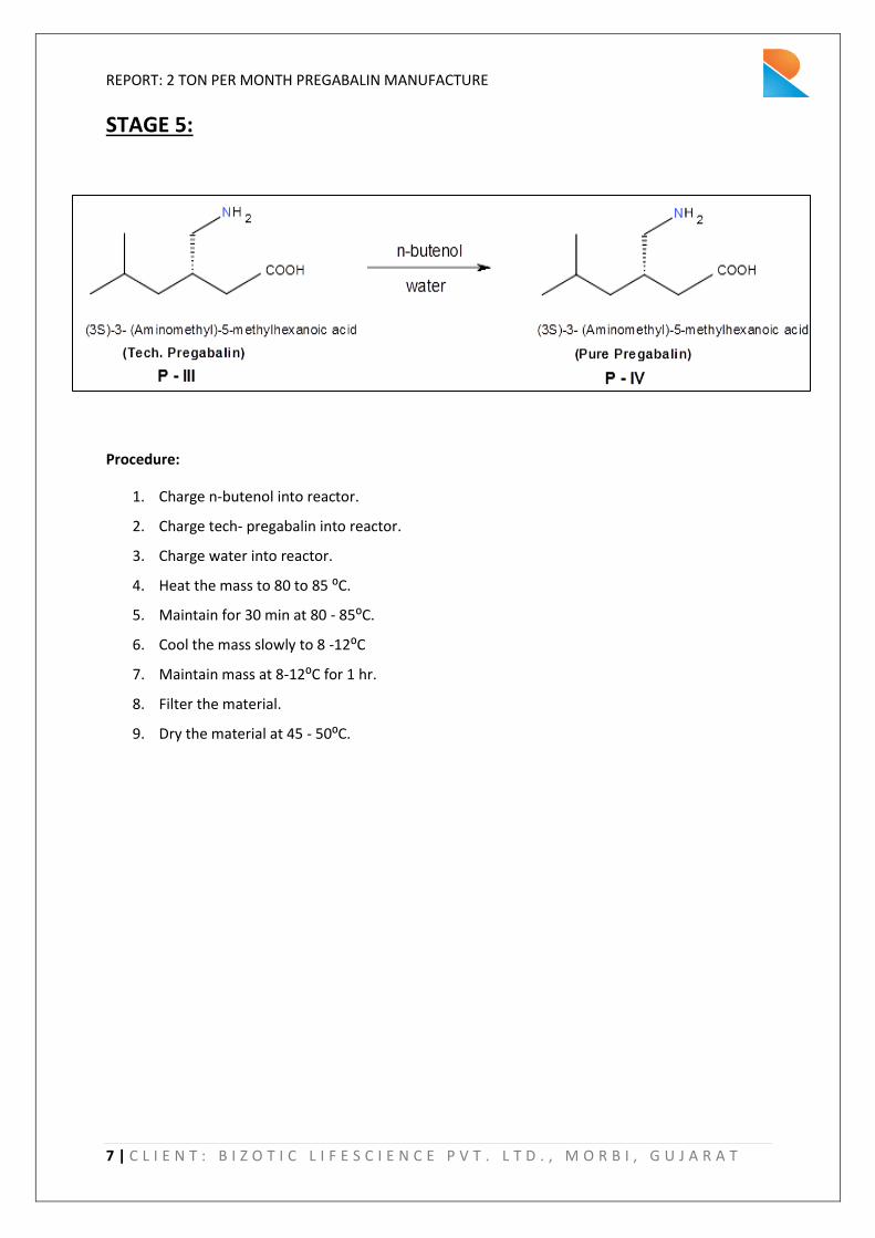
STAGE 5:
Procedure:
1. Charge n-butenol into reactor.
2. Charge tech- pregabalin into reactor.
3. Charge water into reactor.
4. Heat the ass to 8 to 8 ⁰C.
5. Maintain for 30 min at 80 - 8 ⁰C.
6. Cool the mass slowly to 8 - ⁰C
7. Maintain mass at 8- ⁰C for hr.
8. Filter the material.
9. Dry the material at 45 - ⁰C.

REPORT: 2 TON PER MONTH PREGABALIN MANUFACTURE
8 | C L I E N T : B I Z O T I C L I F E S C I E N C E P V T . L T D . , M O R B I , G U J A R A T
STAGE 1A:
Procedure:
1. Charge MLR in to the reactor.
2. Charge sodium Hydroxide solution in to the reactor.
3. Maintain the mass for 1 hr under stirring.
4. Settle the mass for 30 mins.
5. Separate the lower chloroform layer.
6. Slowly adjust pH 2-3 using Con. Hydrochloric acid.
7. Mai tai the ass at to ⁰C for hr.
8. Centrifuge the material.
9. The wet cake is ready for next stage.

REPORT: 2 TON PER MONTH PREGABALIN MANUFACTURE
9 | C L I E N T : B I Z O T I C L I F E S C I E N C E P V T . L T D . , M O R B I , G U J A R A T
STAGE 1B:
Procedure:
1. Charge toluene into the reactor.
2. Charge unwanted isomer into reactor.
3. Charge PTSA into reactor.
4. Heat the mass to reflux temperature (110- ⁰C for hrs.
5. Cool the mass to 60- ⁰C.
6. Slowly charge sodium hydroxide solution (dissolved sodium hydroxide in water lot-1).
7. Maintain the reaction at 60- ⁰C for -3 hrs.
8. Cool the mass to 20- ⁰C.
9. Separate the layers.
10. Take aq. Layer in to the reactor.
11. Adjust the pH to 2-2.5 using Con. HCl.
12. Cool the mass to 10- ⁰C.
13. Maintain mass for 1 hr at 10- ⁰C.
14. Filter the material through a centrifuge.
15. Wash the material with water (Lot-2) at 10- ⁰C.
16. Dry the material at 50- ⁰C till m/c less than 1.0%.
17. The material is ready to be recycled to Stage 1.
REPORT: 2 TON PER MONTH PREGABALIN MANUFACTURE
10 | C L I E N T : B I Z O T I C L I F E S C I E N C E P V T . L T D . , M O R B I , G U J A R A T
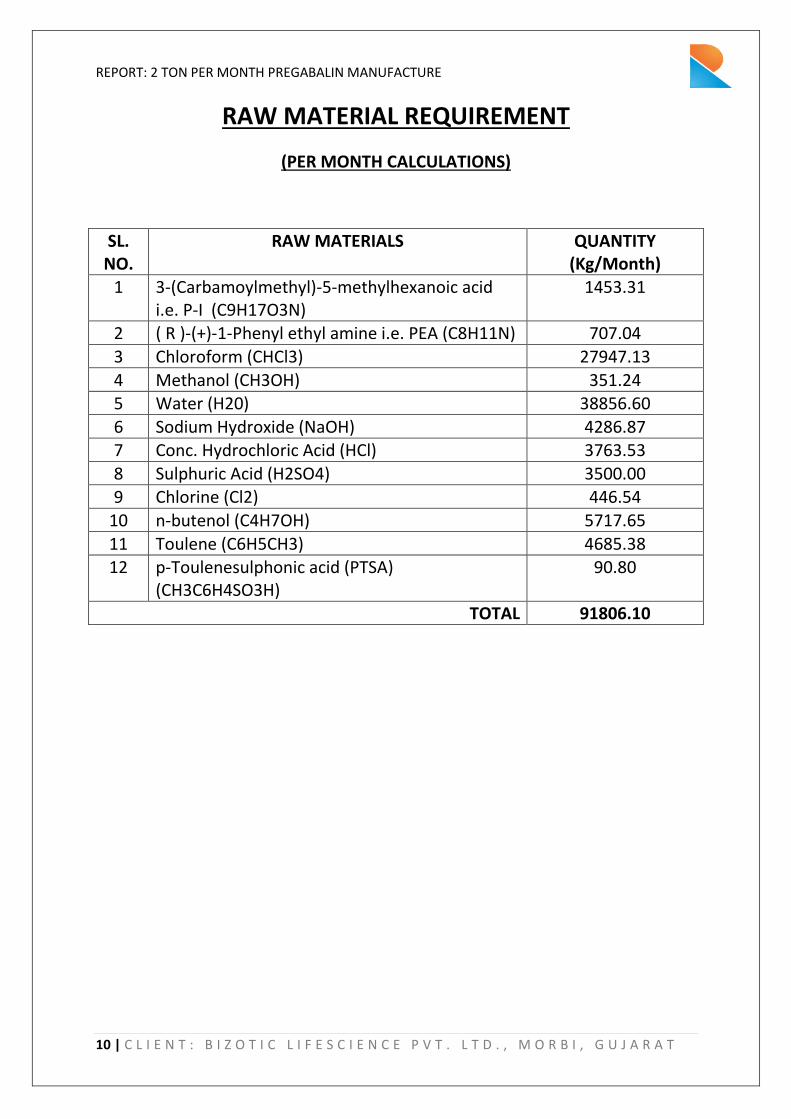
RAW MATERIAL REQUIREMENT
(PER MONTH CALCULATIONS)
SL.
NO.
RAW MATERIALS QUANTITY
(Kg/Month)
1 3-(Carbamoylmethyl)-5-methylhexanoic acid
i.e. P-I (C9H17O3N)
1453.31
2 ( R )-(+)-1-Phenyl ethyl amine i.e. PEA (C8H11N) 707.04
3 Chloroform (CHCl3) 27947.13
4 Methanol (CH3OH) 351.24
5 Water (H20) 38856.60
6 Sodium Hydroxide (NaOH) 4286.87
7 Conc. Hydrochloric Acid (HCl) 3763.53
8 Sulphuric Acid (H2SO4) 3500.00
9 Chlorine (Cl2) 446.54
10 n-butenol (C4H7OH) 5717.65
11 Toulene (C6H5CH3) 4685.38
12 p-Toulenesulphonic acid (PTSA)
(CH3C6H4SO3H)
90.80
TOTAL 91806.10

REPORT: 2 TON PER MONTH PREGABALIN MANUFACTURE
11 | C L I E N T : B I Z O T I C L I F E S C I E N C E P V T . L T D . , M O R B I , G U J A R A T
LIST OF PROPOSED EQUIPMENTS AND UTILITIES
PROPOSED EQUIPMENT LIST SL.
NO. AREA EQUIPMENT MOC STAGE
1 REACTION SS REACTOR SS 316 1
2 REACTION SS REACTOR SS 316 2
3 REACTION SS REACTOR SS 316 3
4 REACTION GLASS LINED REACTOR 2
5 REACTION CENTRIFUGE 1
6 REACTION CENTRIFUGE MSRL 2
7 REACTION CENTRIFUGE SS 316 4
8 REACTION MIXING VESSEL SS 316 4
9 REACTION SPARKLER FILTER SS 316 3
10 REACTION BUFFER STORAGE FOR SODIUM
HYPOCHLORIDE SS 316 3
11 PP REACTION SS REACTOR SS 316 5
12 PP REACTION CENTRIFUGE SS 316 5
13 PP REACTION TRAY DRYER SS 316 5
14 POWDER
PROCESSING ROTOCONE VACUUM DRYER SS 316
15 POWDER
PROCESSING MULTIMILL SS 316
16 POWDER
PROCESSING SHIFTER SS 316
17 RECOVERY SS REACTOR SS 316 1A
18 RECOVERY SS REACTOR SS 316 1B
19 RECOVERY GLASS LINED REACTOR 1A
20 RECOVERY GLASS LINED REACTOR 1B
21 RECOVERY CENTRIFUGE MSRL 1A
22 RECOVERY CENTRIFUGE MSRL 1B
23 RECOVERY TRAY DRYER SS 316 1B
24 RECOVERY BUFFER STORAGE FOR MLR FROM STAGE 1 SS 316 1A
25 STORAGE P-I STORAGE TANK
26 STORAGE CHLOROFORM STORAGE TANK
27 STORAGE METHANOL STORAGE TANK
28 STORAGE PHENYL ETHYL AMINE STORAGE TANK
29 STORAGE SODIUM HYDROXIDE STORAGE TANK
30 STORAGE CONC. HYDROCHLORIC ACID STORAGE
TANK
31 STORAGE SULPHURIC ACID STORAGE TANK
32 STORAGE CHLORINE STORAGE TANK

REPORT: 2 TON PER MONTH PREGABALIN MANUFACTURE
12 | C L I E N T : B I Z O T I C L I F E S C I E N C E P V T . L T D . , M O R B I , G U J A R A T
33 STORAGE CARBON DIOXIDE STORAGE TANK
34 STORAGE n-BUTENOL STORAGE TANK
35 STORAGE P-IV STORAGE TANK (FINAL PRODUCT)
36 STORAGE p-TOULENE SULPHONIC ACID STORAGE
TANK
37 STORAGE TOULENE STORAGE TANK
UTILITIES
SL. NO. NAME NO
1 HOT WATER GENERATOR 1
2 AIR DRYER + COMPRESSOR 1
3 DG SET 1
4 DM PLANT 1
5 COOLING TOWER 1
6 CHILLING PLANT 2
7 AHU 6
OTHER ROOMS IN PP AREA SL. NO. NAME NO
1 FP STORAGE ROOM 1
2 QUARRANTINE ROOM 1
3 PACKING AND LABELLING ROOM 1

REPORT: 2 TON PER MONTH PREGABALIN MANUFACTURE
13 | C L I E N T : B I Z O T I C L I F E S C I E N C E P V T . L T D . , M O R B I , G U J A R A T
EQUIPMENT CAPACITY
SUGGESTED EUIPMENT CAPACITY
SL.
NO.
EQUIPMENT STAGE CAPACITY
1 SS REACTOR 1 3 KL
2 SS REACTOR 2 3 KL
3 SS REACTOR 3 3 KL
4 GLASS LINED REACTOR 2 3 KL
5 SS REACTOR 5 3 KL
6 SS REACTOR 1 A 3 KL
7 SS REACTOR 1 B 3 KL
8 GLASS LINED REACTOR 1 A 3 KL
9 GLASS LINED REACTOR 1 B 3 KL
10 CENTRIFUGE 1
11 CENTRIFUGE 2
12 CENTRIFUGE 4
13 CENTRIFUGE 5
14 CENTRIFUGE 1 A
15 CENTRIFUGE 1 B
16 MIXING VESSEL 4 3 KL
17 AHUs 200 CFM

REPORT: 2 TON PER MONTH PREGABALIN MANUFACTURE
14 | C L I E N T : B I Z O T I C L I F E S C I E N C E P V T . L T D . , M O R B I , G U J A R A T
WATER BALANCE
WATER
CONSUMPTION
GENERATION/LOSSES ETP SECTION
SL.
NO
USERS
FRESH
WATE
R FEED
(m3/d
ay)
RECYCL
E FEED
(m3/da
y)
TOTAL
FEED
(m3/d
ay)
EVAPOR
ATION
LOSSES
(m3/da
y)
GROUN
D/SUM
P PIT
LOSSES
(m3/da
y)
EFFLUENT
GENERATI
ON TO ETP
(m3/day)
RECYCLE
@40 %
EFFLUENT
GENREAT
ION BACK
TO PLANT
(m3/day)
DISPOS
AL to
CETP
(m3/da
y)
A Domestic 1 0 1 0.03 0.2 0.77
1.27
1.91
B Industrial
1 Process 1.6 0 1.6 0.2 0
2 Washing 2 0 2 0.06 1.94
3 Boiler Feed 0.5 0 0.5 0.05 0.45
4 Cooling
Makeup
0.5 0 0.5 0.475 0.025
5 Gardening 0.5 2 2.5 2.5
6 Others
(R.O. &
Softening
Rejects)
0.5 0.5
0.815 2.7 3
TOTAL 6.6 2 8.6 6.7 3.19

REPORT: 2 TON PER MONTH PREGABALIN MANUFACTURE
15 | C L I E N T : B I Z O T I C L I F E S C I E N C E P V T . L T D . , M O R B I , G U J A R A T
WATER CHART
REPORT: 2 TON PER MONTH PREGABALIN MANUFACTURE
16 | C L I E N T : B I Z O T I C L I F E S C I E N C E P V T . L T D . , M O R B I , G U J A R A T
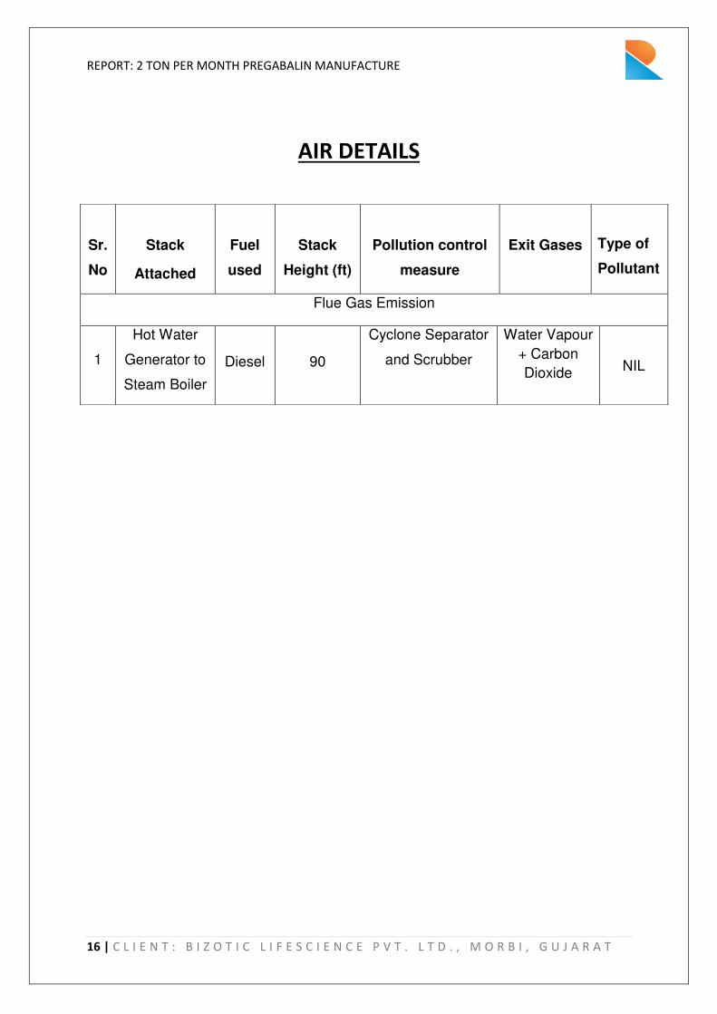
AIR DETAILS
Sr.
No
Stack
Attached
Fuel
used
Stack
Height (ft)
Pollution control
measure
Exit Gases
Type of
Pollutant
Flue Gas Emission
1
Hot Water
Generator to
Steam Boiler
Diesel 90
Cyclone Separator
and Scrubber
Water Vapour
+ Carbon
Dioxide
NIL

REPORT: 2 TON PER MONTH PREGABALIN MANUFACTURE
17 | C L I E N T : B I Z O T I C L I F E S C I E N C E P V T . L T D . , M O R B I , G U J A R A T
DETAILS OF PROPOSED EFFLUENT TREATMENT PLANT
The steps followed in the Effluent Treatment Plant are described below:
1. The raw effluent is being passed through the Oil & Grease Chamber for preliminary
treatment and collected in the Collection tank where chemical dosing is carried out to
neutralize the effluent.
2. The effluent from the collection tank is pumped to Primary Settling Tank (PST). The
sufficient retention time is provided in PST to settle down the coagulated mass.
3. The sludge generated from the bottom of the PST is collected in the Sludge Sump. The
filtrate from the Sludge Sump is conveyed to the Filter Press.
4. The over flow of PST is conveyed to Anaerobic Reactor for reduction of organic loading by
Anaerobic treatment.
5. From the Anaerobic Reactor the effluent is conveyed to Aeration Tank, where sufficient
retention time is provided for Biological Treatment of the Effluent.
6. The over flow of Aeration Tank is conveyed to Secondary Settling Tank for further settling
of coagulated mass. The settled biomass is recycled and excess biomass is drained to
Sludge Sump.
7. The over flow of SST is collected in the Treated Water Sump. After treated water sump,
Filter has been provided before its final discharge to CETP.

REPORT: 2 TON PER MONTH PREGABALIN MANUFACTURE
18 | C L I E N T : B I Z O T I C L I F E S C I E N C E P V T . L T D . , M O R B I , G U J A R A T
LINE DIAGRAM OF EFFLUENT TREATMENT PLANT
Sr. No. Treatment Unit No. of Units
1 Oil and Grease Tank 1
2 Collection cum Equalization Tank 1
3 Primary Settling Tank 1
4 Anaerobic Reactor 1
5 Aeration Tank 1
6 Secondary Settling Tank 1
7 Treated Water Sump 1
8 Pressure Sand Filter 1
10 Sludge Sump 2
11 Filter Press 1

SF XXX
R XXXGLR XXX D XXX
T XXXCF
XXX
SS REACTORGLASS LINED
REACTOR
SPIN DRYER
TANK CENTRIFUGE SPARKLER
FILTER
SYMBOL
T 004
T 003
T 002
BS 002
R 001T 005
R 002 R 003
GLR 001
R 004
R 006R 005
GLR 003GLR 002
T 006
BF 001
SF 001
T 010
MLR
(TO ETP)
T 012
T 013
CF
001
CF002
CF
003
CF004
CF006
DM WATER
T 011
CF005
TO
CHLOROFORM
RECOVERY
TOULENE
LAYER
TO
CHLOROFORM
RECOVERY
BLOCK DIAGRAM FOR MANUFACTURE OF PREGABALIN
T 007
MV OO1
MLR
(TO ETP)
REACTION AREA PP REACTION AREA
POWDER PROCESSING AREA
MM 001RCVD001
SH
001
MLR
(TO ETP)
MLR
(TO ETP)
MLR
(TO ETP)
MM XXXRCVDXXX
SH
XXX
SHIFTER MULTIMILL ROTO-CONE
VACUUM DRYER
SL. NO. EQUIPMENTTAG NO.AREA
9
2
3
4
5
6
7
10
11
12
13
14
15
16
17
18
19
20
21
22
23
24
25
8
1 REACTION
PP
PP
PP RCVD 001
MM 001
SH 001
ROTOCONE VACUUM DRYER
MULTIMILL
SHIFTER
PP-REACTION
PP-REACTION
PP-REACTION
REACTION
REACTION
REACTION
REACTION
REACTION
REACTION
REACTION
REACTION
RECOVERY
RECOVERY
RECOVERY
RECOVERY
RECOVERY
RECOVERY
RECOVERY
RECOVERY
TRAY DRYER (STAGE 5)
CENTRIFUGE (STAGE 5)
SS REACTOR (STAGE 5)
SPARKLER FILTER (STAGE 3)
MIXING VESSEL (STAGE 4)
SS REACTOR (STAGE 1)
SS REACTOR (STAGE 2)
SS REACTOR (STAGE 3)
GLASS LINED REACTOR (STAGE 2)
CENTRIFUGE (STAGE 1)
CENTRIFUGE (STAGE 2) [MOC: MSRL]
CENTRIFUGE (STAGE 4)
SS REACTOR (STAGE 1A)
SS REACTOR (STAGE 1B)
GLASS LINED REACTOR (STAGE 1A)
GLASS LINED REACTOR (STAGE 1 B)
BUFFER STORAGE FOR MLR FROM STAGE 1 (STAGE 1A)
TRAY DRYER (STAGE 1B)
CENTRIFUGE (STAGE 1B) [MOC: MSRL]
CENTRIFUGE (STAGE 1A) [MOC: MSRL]
MV XXX
MIXING VESSEL
R 001
R 002
R 003
GLR 001
CF 001
CF 002
CF 003
MV 001
SF 001
R 004
CF 004
TD 001
R 005
R 006
GLR 002
GLR 003
CF 005
CF 006
TD 002
BS 002
T 001
T 002
T 003
T 004
T 005
T 006
T 007
T 008
T 009
T 010
26
27
28
34
33
32
31
30
29
STORAGE
STORAGE
STORAGE
STORAGE
STORAGE
STORAGE
STORAGE
STORAGE
STORAGE
STORAGE
T 008
T 009
REACTION BUFFER STORAGE FOR SODIUM HYPOCHLORIDE (STAGE 3)BS 001
D 001
D 002
[ TO
BUTENOL
RECOVERY]
T 01135 STORAGE
T 01236 STORAGE
T 001
T 01337 STORAGE
P-I STORAGE TANK
CHLOROFORM STORAGE TANK
METHANOL STORAGE TANK
PHENYL ETHYL AMINE STORAGE TANK
SODIUM HYDROXIDE STORAGE TANK
CONC. HYDROCHLORIC ACID STORAGE TANK
SULPHURIC ACID STORAGE TANK
CHLORINE STORAGE TANK
CARBON DIOXIDE STORAGE TANK
n-BUTENOL STORAGE TANK
P-IV STORAGE TANK (FINAL PRODUCT)
p-TOULENE SULPHONIC ACID STORAGE TANK
TOULENE STORAGE TANK
BS XXX
BUFFER STORAGE
NOTE:
1) FOR STAGE 3, WE FIRST MAKE SODIUM
HYPOCHLORIDE IN R 003, TRANSFER IT TO THE BUFFER
STORAGE BS 002, THEN WE USE THE SAME REACTOR R
003 FOR MAKING TECH PREGABALIN AND THE
TRANSFER THE MATERIAL TO SPARKLER FILTER SF 001.
2) LATER IN STAGE 4, WE HAVE REPLACED THE
REACTOR WITH A MIXING VESSEL, MS 001 IN WHICH
ADDITION OF SULPHURIC ACID IS DONE.
3) FOR SEPARATION OF CHLOROFORM AND PEA FROM
CHLOROFORM LAYER OF STAGE 1A GLR 002, WE CAN
USE SAME SSR/GLR AS STAGE 1A

9000
17
70
5
REACTION ZONE
(CLASSIFIED)
ADM . BUILDING
6 M Wide Road
MAIN GATE
REACTION ZONE
(NON - CLASSIFIED)
UTILITY SHED
TA
NK
FA
RM
AR
EA
ET
P S
EC
TIO
N
STP SECTION
LABOUR QTRS
AREA
PO
WD
ER
SE
CT
ION
CANTEEN
RAW MATERIAL
STORAGE AREAFG STORAGE AREA
CORRIDOR
CO
RR
IDO
R
GARDEN AREA
HT AREA
6 M Wide Road
SE
CU
RIT
Y C
AB
IN
VILLAGE ROAD
VIL
LA
GE
RO
AD
30
00
3000200397899 15036
62251
10
33
90
60950
103399
30192
18
59
71
00
00
20
00
10758
26
93
4
60
00
2467812758
60
00
10
00
0
12950 30000
42950
45
96
13
19
8
60000
3000
12
00
0
BIZ
OT
IC L
IFE
SC
IEN
CE
PV
T. L
TD
.
AD
DR
ES
S ; P
LO
T N
O. -1
52
/4/1
, N
EW
KH
AR
EC
HIY
A ,
MO
RB
I , G
UJA
RA
T
MA
DE
BY
: M
ON
AL
ISA
DU
TT
A
CH
KD
BY
: A
KP
DA
TE
: 1
5/1
0/2
01
5
DR
AW
ING
NO
: B
IZ/M
OR
/00
2
RE
VIS
ION
NO
: -
IND
US
TR
Y T
YP
E: P
HA
RM
AC
EU
TIC
AL
S A
PI
LA
YO
UT
PL
AN
OF
BIZ
OT
IC L
IFE
SC
EIN
CE
PV
T.
LT
D.
, A
PI
PL
AN
T,
MO
RB
I PR
OJE
CT
CO
NS
UL
AT
AN
TS
: L
AC
IME
HC
PR
OT
EC
H
PV
T.
LT
D,
VA
DO
DA
RA
NO
TE
: 1
. A
LL
DIM
EN
SIO
NS
AR
E I
N M
M U
NL
ES
S S
PE
CIF
IED