report prav 4.14 evaluation of geophysical borehole ... · evaluation of geophysical borehole...
TRANSCRIPT

Report Prav 4.14
EVALUATION OF GEOPHYSICAL BOREHOLE
STUDIES
by
Otto Brotzen
Oscar Duran
K-Å Magnusson
Geological Survey of Sweden, February 1980
Phil Nelson & Richard Rachiele
Assisted with the borehole measurements
in Stripa, borehole SBH-1.
Lawrence Berkeley Laboratory
Berkeley, California, USA

SUMMARY
Four studies concerning geophysical investigations and TV
inspection in boreholes in connection with KBS studies
at Finnsjö, Karlshamn, Kråkemåla and Stripa and PRAV's
studies at Studsvik have been evaluated. SGU*s cooperation
with Lawrence Berkeley Laboratories (LBL, P. Nelson and
his colleagues) at Stripa have been very valuable. This
has made a balanced evaluation of both SGU's and LBL's
borehole measurement systems possible. This has led to
proposals concerning the choice of instruments and methods
for future studies and a review of future work required.
The evaluation has shown that the following borehole
measurements are of primary interest in the continued work:
Determinations of temperature and resistivity of the borehole
liquid, resistance and resistivity measurements, SP, Sonic,
Caliper and VLF.
TV inspection, IP and gamma-gamma should also be included in
the arsenal of available test methods, while slingram in its
current form should only used be in special cases.

TABLE OP CONTENTS Page
1
3
5
8
8
SUMMARY
1. BACKGROUND
2. SCOPE OF THE WORK
3. REVIEW OF THE MEASUREMENT METHODS
4. CHARACTERIZATION AND EVALUATION
4.1 The borehole liquid
4.2 Mineralogical and chemical composition of the
bedrock 9
4.3 Fracture content of the bedrock 15
5. DISCUSSION 27
6. PROPOSALS FOR CONTINUED WORK 32
6.1 Instrument development 32
6.2 Processing, theoretical studies and back-up
experiments 33
6.3 Trial measurements in the field 34
FIGURES Fig
SCHEMATIC DIAGRAM
TEMPERATURE GRADIENTS
BOREHOLE GRAPHS
Borehole K 2, Kråkemåla
Permeability
Resistivity of the borehole liquid
BOREHOLE GRAPHS
Borehole SBH-1, Stripa
Natural gamma
Gamma-gamma
Thermal neutron
Resistivity (normal 1.6 m)
4 and 5

Ill
BOREHOLE GRAPHS
Borehole SBH-1, Stripa
Spontaneous potential (SP)
Induced polarization (IP)
VLF
6 and 7
BOREHOLE GRAPHS
Borehole SBH-1, Stripa, 270-370 m section
Gamma-gamma
Thermal neutron
Resistivity (Lateral 1.0 and Normal 1.6 m)
Sonic (acoustic arrival time)
TV INSPECTION AND DIFFERENTIAL RESISTANCE
ACOUSTIC WAVEFORM AND DIFFERENTIAL RESISTANCE
BOREHOLE GRAPH
Borehole SPH-1, Stripa, 270-370 m section
Caliper
Differential resistance
Sonic (acoustic arrival time)Resistivity (Lateral 1.6m and Normal 1.6 m)
BOREHOLE GRAPHS
Borehole A 1, Avrö
Resistivity of borehole liquid
SP
Point resistance
Resistivity (norma. 1.6, 5.2 and 16 m and lateral
1.6 m, 5.2 m and 16.8 m)
Borehole siingram 5 m and 40 m

iiii
BOREHOLE GRAPHS
Borehole K 3, Kråkornala
Resistivity (Lateral 1.6 m, 5.2 m and 16.8 in)
Natural gamma
SIingram 5 m and 40 m
BOREHOLE GRAPHS
Borehole Pi 1, Finnsjö
Resistivity of borehole liquid
SP
Point resistance
Resistivity (normal 1.6 m, 5 m and 16 m)
Resistivity (lateral 1.6 m, 5 m and 16 m)
VLF
APPENDICES
CORE AND TV INSPECTION
BIBLIOGRAPHY
A 1
A 2

EVALUATION OF GEOPHYSICAL BOREHOLE STUDIES
1. BACKGROUND
In connection with site studies for deep rock repositories,
drillings are used to shed light on the bedrock and
groundwater conditions. With core drilling, a virtually
continuous sample of the intersected rock species is
obtained, enabling their composition, variation, structure,
fracture content and fracture-filler material to be determined.
The core is inspected mainly visually. More detailed studies
are only made of selected specimens. Geophysical borehole
studies therefore provide valuable supplementary information
on the characteristics and composition of the rock, and can
also provide guidance for sampling for more detailed study
of the drill core.
Drilling without core recovery, which generally costs much
less, can provide certain information on the bedrock through
study of the drill cuttings. In these cases, geophysical
measurement data on the nature of the bedrock are of even
greater value. Regardless of whether the core has been
recovered or not, the boreholes are used for hydrogeological
studies, whereby the water content, permeability and groundwater
pressure of the bedrock at different depths can be deter-
mined by means of special measurements. In addition, water
samples can be taken up for closer study.
The obtained information is limited by the small width of
the boreholes, especially as far as information on ground-
water conditions is concerned. Fractures outside the boreholes
cannot be observed. It is therefore not known which fractures,

while not water-bearing in the boreholes, can become water-
bearing at greater distance from the holes. The orientation
and extent of the intersected water-bearing fracture zones is
generally unknown. The chemical character of the water samples
that are taken up does not coincide exactly with the pressure
and temperature conditions that prevail at the sampling
depth. There are therefore reasons to carry out studies in
the boreholes that shed greater light on conditions at the
depths in question, as well as outside and between existing
boreholes.
Borehole measurements of various types have long been used
in prospecting for groundwater, oil and gas in sedimentary
rock and in prospecting for ore. The need for borehole measure-
ments for rock repositories at great depth in rock species
such as granite and gneiss, however, arose first in connec-
tion with studies concerning the storage of radioactive
waste. Extensive method development is therefore required
for this purpose. Fig. 1.
The Geological Survey of Sweden (SGU) has, on commission for
the National Council for Radioactive Waste (PRAV) and the
Nuclear Fuel Safety Project (KBS), carried out a number of
studies with this purpose. SGU has developed measuring
equipment and carried out extensive borehole measurements
in the KBS study area. On commission for PRAV, SGU has now
carried out an evaluation of the methods tried thus lar.
Borehole measurements concerning the chemistry of the ground-
water are not included in this review.
Thanks to the fact that LBL (P. Nelson and his colleagues)
has made the results from borehole measurements in Stripa
available to us, LBL's methods have also been evaluated from
SGU's perspective.

2. SCOPE OF THE WORK
The work has included the following parts:
Comparison between core mapping and TV inspection
of the borehole walls;
Review of measuring principles and applicability
of SGU's system for logging of boreholes
Comparative analysis of borehole measurements, carried
out by Lawrence Berkeley Laboratories (LBL, P. Nelson
and R. Rachiele) and by SGU in a borehole at the
Stripa mine
Review of 0. Landström1s results concering the prelimin-
ary study of the boreholes in the new study area at
Studsvik.
Related literature studies.
Appendix 2 contains a bibliography of relevant literature. The
processing of the different measurement results has included cal*
culation of suitable parameters from raw data and their plotting
as a functions of borehole length (depth), plus graphic presenta-
tion together with other basic results, e.g. permeability.
Selected parameters have also been plotted against each other.
In this manner, a body of data has been obtained as a
basis for the evaluation of the individual geophysical study
methods.

In addition to personnel from SOU, the following groups have
carried out participated in the studies included in the
evaluation:
AB Energiteknik, Studsvik (O. Landström) performed
temperature measuremenhs and determinations of the radon
content of the groundwater and the natural gamma radiation
of the bedrock in boreholes at Studsvik.
The Department of Geology at the Chalmers University
of Technology measured the temperature of the ground-
water in a number of the KBS boreholes.
Lawrence Berkeley Laboratories (LBL, P. Nelson) allowed us
access to an extensive, unpublished body of data from one of
the boreholes at Stripa. These measurements are discussed in
the following presentation.
The TV instrumentation for inspection of the boreholes
and recording on videotape was made by Undervattensfoto AB.
A large portion of SGU's borehole measurements have already
been reported in KBS technical report No. 61 (1978).

3. REVIEW OF THE MEASUREMENT METHODS
Two different combinations of measurement methods, LBL's
and SGU's, provided most of the data dealt with here.
LBL's system included the following probes:
Caliper, a mechanical sensing of variations in borehole
diameter.
Temperature, determination of the temperature of the
borehole liquid (the groundwater).
Sonic, the arrival time of elastic waves through 0.3 m
length of the bedrock around the borehole wall. The
result of incident waves (the wave form) is recoded
photographically.
Natural gamma, measurement of the bedrock's natural
radioactivity, its gamma radiation.
Gamma-gamma, measurement of the bedrock's absorption
of gamma radiation.
Neutron, the ability of the bedrock to retard and
capture neutrons is determined over a length of 18 cm.
A presentation with comments and examples of measurements
with the LBL system has been provided by Nelson et al (1979).
Determinations of the natural gamma radiation and of the
temperature of the borehole liquid have also been included
in SGU's studies. In addition, the following electric
parameters were determined.

Resistivity of the borehole liquid
Spontaneous potential (SP), spontaneous electric poten-
tials caused by chemical gradients (ion concentrations,
redox processes) or hydrodynamic flow potentials. See
Hallenburg (1971).
t
Induced polarization (IP), electro-chemical polarization
effects in the bedrock.
Point resistance, the electrical contact resistance
around an electrode lowered into the borehole.
Differential point resistance, the resistance between
two electrodes located very near each other.
Normal resistivity, the average resistivity in rock
volume around the borehole with a nearly symmetrical
distribution of current density. Four different
electrode configurations of different sizes have been
used.
Lateral resistivity, similar measurement with assymmetric
current density distribution, whereby three electrode
configurations have been used.
SIingram effects, i.e. the field strength of the secondary
electro-magnetic field induced around electric conductors
in the bedrock subjected to an electromagnetic primary
field from an alternating-current coil (the transmitter).
The transmitter and the receiver are lowered into the bore-
hole.

VLF effects, i.e. similar effects, except that the
primary field in this case stems from a radio transmitter
in England (GBR) with low frequency JYery Low Frequency),
where the receiver is lowered into the borehole.
The TV inspection of boreholes, which was carried by SGU
on behalf of KBS, constitutes an important part of this
evaluation. The geochemical borehole measurements also
performed by SGU are not dealt with in the following.
Other measurement methods
There are many methods for geophysical measurements in bore-
holes that have not been tested thus far. In this connection,
methods which may be of direct interest for borehole studies
for rock repositories should be mentioned, for example
methods that work with pressure and shear waves in different
frequency ranges, such as the Televiewer method. This method
was developed by the US Geological Survey. Instruments for
borehole seismics are under development by a.g. POA. LBL is
experimenting with the ultrasonic detection of rock fractures.
On special assignment, SGU is also monitoring the method develop-
ment work within radar technology for geophysical surveys that is
currently being done in the United States and Canada, among other
countries.

4. CHARACTERIZATION AND EVALUATION
The study methods used (LBL's and SGU's) can be divided into
methods that investigate the borehole liquid and methods that
investigate the mineral content and fracture content of the
bedrock. In realitity, the measurement results often reflect,
a combination of these factors.
4.1 The borehole liquid
After completed core drilling, the boreholes and the open
fractures in the walls of the hcle are normally filled with
flushing liquid (water) and partially by drilling sludge
as well. They can be evacuated by means of compressed air, which
is injected near the bottom of the borehole, after which surround-
ing groundwater flows into the hole.
The temperature is measured with a thermistor thermometer
with an absolute error of +_ 0.06°C and a relative error of
+_ 0.004°C. The measurement is simple and quick (about 100 tn/h).
The temperature rises with increasing depth. The gradient in
different holes varies, see Fig. 2. It is smaller in
permeable bedrock, and especially in areas with an inflow
of groundwater (borehole K 2). See Lewis & Becic (1977).
There are clear discontinuities in the temperature curves.
These discontinuities correspond to zones of increased
permeability and pressure difference between fracture
zone and borehole.
Resistivity. The electrical resistivity of the borehole liquid
was measured between two electrodes approximately 4 cm apart.
The electrodes are placed in a plastic tube open at both ends.

The plastic tube shields the electrodes from the influence of
the borehole wall. The measurement is quick and simple.
Resistivity is inversely proportional to the ionic strength
of the borehole liquid, and approximately to its salinity and
density. As a rule, resistivity decreases with increasing depth,
which reflects a stratification with increasing salinity towards
increasing depth. There are discontinuities in the resistivity
curve, similar to those in the temperature curves, which are
caused by an inflow or outflow of water of differing salinity.
See Fig. 3.
Evaluation. Both the temperature and resistivity measurements
provide valuable and fundamental information. The measuring
methods are quick, easy and inexpensive. The connection be-
tween discontinuities i i temperature and resistivity and
individual water-bearing zones in the boreholes indicates certain
possibilities for shedding light on groundwater movements and, to
some extent, water pressure conditions with these measure-
ments. Continued measurements and development of instruments and
methods of interpretation are therefore well justified.
4.2 Mineralogical and chemical composition of the bedrock
The mineralogical and chemical composition of the bedrock
can be studied in detail in the drill core. As a rule,
qualitative observations are made quickly and efficiently
in connection with the routine core mapping work. Borehole
measurements contribute quantitative data and can, in combina-
tion, also permit a geophysical subdivision of the intersected
bedrock as well, see Figs. 4, 5, 6 and 7.

10
Natural gamma radiation in the boreholes stems from the
immediately surrounding bedrock's content of potassium,
uranium and thorium, which often reflects the general
mineral composition of the bedrock. Distinct radioactive
mineralizations can also occur. The borehole measurement
is quick and easy. When anomalous radiation levels are found, a
spectrometric subdivision can be made and the proportions between
potassium, uranium and thorium can be determined. The proportion
between uranium and thorium can indicate zones that have been al-
tered by the water flowing through them, Keys and Sullivan (1979),
Keys (1979) .
The gamma gamma (density) log has an Am radiation sourceo
of 16 millicuries ( 6 x 10 Bq) located 57 mm from the
detector. The absorption of the source's gamma ratiation
is proportional to the electron density of the surrounding
medium. In most rock-forming substances, electron density
is proportional to the density of the substances. The
short distance between the source and the detector gives
the instrument high resolution. The measurement is performed
continuously, and is easy and quick.
The neutron log has a 1.4 caries (5 x 10 Bq) Am-Be neutron
source and an He-3 detector. The distance between source and
detector is 18 cm, and the effective radius of the volume
that is studied is about 40 cm in normal bedrock with low
porosity. The water content of the rock retards the neutrons
from the source and reduces the number of detected counts
per second. This reduction is proportional to the logarithm
of the total water content of the rock, Nelson and Glenn (1975).
This water content is dominated (except in marked fracture
zones), in Swedish rocks of interest in this connection, by chemi-

11
cally bound water, which normally amounts to between 0.5 and 5 %
by weight. The rock's content of fracture-borne flowing ground-
water generally only reaches around around one-tenth of these
values.
A review of the measurements at Stripa also indicates that
the iron content of the rock can reduce the count number,
which may be connected with the larger cross-section of the
iron atoms for neutron capture. See Figs. 4 and 5. Chlorite-
rich zones are distinguished in this connection by high
contents of both water and iron, while iron-ore-, pyroxene-
and hornblende-bearing zones have elevated iron contents
but fairly normal water contents. This means that the neutron
log is sensitive to the content of dark iron-rich minerals,
and thereby more sensitive to mineralogical variations than to
water-bearing fracture zones. This is exemplified in Pigs. 4, 5
and 8 by the greenstone section, whose deviation is on the order
of 900 counts per second, compared with the fracture zones'
deviation of 300 counts/second. In addition, hydrated fracture
minerals usually occur in the fracture zones, for example
chlorite. The quantity of free ground water in the section can
therefore not be determined conclusively from the neutron log.
The measurement is relatively quick and easy, but the
radiation source requires certain handling and storage
precautions.
Spontaneous potential (SP), i.e. the natural electric
potentials in the bedrock, is measured as the potential
difference between a mobile electrode down in the borehole
and a fixed electrode up on the ground, or between two mobile
electrodes at a fixed distance from each other in the bore-
hole. The electrodes are copper/copper sulphate combinations,

12
which are not polarized but provide good earthing contact.
The potential is a total effect, which can written schemati-
cally as follows:
E s P = Eredox w h e r e
E J O X arises due to redox processes, ED arises due to
diffusion processes and E_ is an electrokinetic effect due to
the groundwater flow through the bedrock around the measur-
ing electrode.
The redox contribution occurs around minerals whose redox
potential deviates from that of the surrounding ground
water. Iron pyrite and other sulphide minerals, as well
as graphite and magnetite, produce this type of potential,
see Figs. 6 and 7. It c<m reach considerable strength,
Sato & Mooney (1960). The borehole measurement at Stripa,
for example, shows that pyrite-filled fractures in the
granite give about -150 mV, and -400 mV is measure.3 at
an iron ore layer. Unmineralized rock species also exhibit
SP variations, although of smaller magnitude.
Diffusion potentials arise when chemical concentration
gradients occur in the groundwater and differences exist
in the mobility of the positive and negative irons,
Hallenburg (1971). Membrane effects can contribute to this.
The concentration gradients are detected by measurement
of the resistivity of the groundwater.
Flow potentials arise when the groundwater moves through
narrow fractures or pores, since the distribution of
positive and negative charges is not uniform near the
face of the rock, Hallenburg (1971).

13
Where the water pressure in the borehole deviates from that
in the environment, these types of water flow take place,
which is reflected both in the temperature and resistivity
of the water. Flow and diffusion potentials therefore often
occur in combination. Examples of SP effects in connection
with permeable zones and changes in the resistivity of the
borehole liquid can be seen in bh Kråkemåla 3 around 280,
380 and 505 m, and in Ävrö 1 at 435 m, see Fig. 12. SP measure-
ment is quick and easy.
Induced polarization (IP). IP effects occur in the form of
a residual potential caused by electrochemical processes in
the interface between the groundwater and the conductive
minerals in the bedrock after an electric current pulse
has been transmitted through the bedrock. The IP effect
therefore reflects the presence of such minerals as well
as their quantity and surface conditions. The measurements
are relatively complicated and time-consuming.
Evaluation. Logging of the natural gamma radiation provides
information that is not obtained from normal core mapping.
It is of interest for the general rock evaluation and can
also indicate and shed light on the presence of mineralization
and leaching processes with respect to potassium, thorium and
uranium. A routine gamma logging of all test holes is there-
fore iustified.
The gamma-gamma probe provides quantitative information
on density variations in the bedrock. See Figs. 4 and 5.
In some cases, this information can be of great value.
In these cases, such logging is well justified, while it
can be dispensed with in other cases.

14
The measurements with the neutron probe in our type of bedrock
sheJ light on the total water content of the bedrock, especially
variations in the rock's content of water-containing minerals,
and possibly also the iron content of the bedrock. See Fig. 8.
Moving groundwater, available for diffusion, has only small
effects and can often be difficult to distinguish. See Pig. 8»
The value of such measurements in core boreholes is therefore
rather small.
Spontaneous potential measurements (SP) provide valuable
information, especially on the presence of electrically
conductive, reducing minerals, even when they are present
at low levels, which can easily be overlooked in connection
with core examination. See Figs. 6 and 7. This is important
for the interpretation of the resistivity measurements, which
is dealt with in the next section.
The SP signals resulting from diffusion and flow phenomena
are also of hydrogeological interest. The SP measurements
therefore have a given place in the borehole studies.
Induced polarization (IP) is even more sensitive than SP when
it comes to detecting electrically conductive minerals in
fine-grained form. See rigs. 6 and 7. The importance of these
minerals is probably greatest on the geochemical side, where
their effect on the Eh, pH and sulphide and sulphate content
of the groundwater can perhaps more easily be demonstrated
with geochemical probes. The IP measurements are therefore
judged to be necessary only in special cases, but not in the
routine work of borehole logging for rock repositories.

15
4.3 Fracture content of the bedrock
The amount of fracturing of the bedrock is an important
factor, which effects the rock's permeability, reaction
surface, strength and ability to absorb deformations.
Fundamental observations are obtained from drill core
mapping and determinations of permeability. The latter
provide a measure of the rock's content of open and
continuous fracture channels, which should also be valuable
in rock mechanics asses>3ments.
Due to the importance of the fracture content of the rock,
many different ways of elucidating on this parameter have been
tested. Each method provides its contribution. An attempt at
evaluation is therefore based on the measurement principles of
the methods, their practical applicability and comparisons be-
tween obtained results. The comparisons are based on the core
mapping and the determinations of permeability, since these are
presently accepted as given constituents of the borehole studies,
TV inspection of the borehole wall is carried out with the
aid of TV camera that can be lowered into the borehole,
with a conical prism head in front of the camera. A compass
has been mounted in the centre of the prism head, enabling
the orientation of the fractured plane to be measured. In
boreholes with a diameter of 56 mm, the camera gives a
complete (360°) picture of 2.5 cm of the length of the
borehole. This gives a /ery high resolution, so that
fractures with an apparent width of only a few tenths
of a millimetre can be observed. Turbid water in the
borehole impairs the quality of the picture, so the bore-

16
hole should be flushed in good time prior to the inspection.
Picture quality is also improved by placing the prism head in
a clear water container, so that the light passes through
only a few millimetres of the borehole water. The TV picture
is recorded on videotape and can therefore be examined
repeatedly and, if necessary, stored.
The agreement between the TV inspections and the core mapping
procedures has been found to be very good. However, TV
inspection is superior in the following respects:
Fractures in the drill core that are induced during the
drilling work and the subsequent handling of the
cores are not present in the borehole wall, which
therefore gives a truer picture of the original
conditions.
The position and orientation of fractures and other
structural elements can often be determined.
An apparent width of the fractures can be determined.
(Permeability measurements show that TV-determined
fracture widths are often larger than the effective
fracture width, which corresponds to the water flow rate.
However, the TV inspection provides a good relative
grouping of the fracture widths.) See Fig. 9.
In addition, TV inspection has led to better insight into the
importance of certain core observations and to proposals for im-
provements of the core examination routines.
The limitations of the TV inspection method are that the

17
degree and nature of the fracture fill cannot be observed
and that observations of rock type and mineral composition
cannot be made.
Comparison with permeability measurement shows that there are
many fractures in the borehole wall which are not associated
with measurable permeability. This applies, for example,
below a depth of 180 m to all individual fractures with an
apparent width of less than 1 mm in bh Kråkemåla 1. As a method,
TV inspection is fairly time- and labour-consuming.
Sonic measurements (LBL) were only carried out at Stripa.
The probe has a magnetostrictive transmitter and piezoelectric
receiver located 0.3 m from the transmitter. The travelling
time it takes for the first p wave to arrive is registered. In
addition, the 4 to 5 first wave peaks are recorded on film.
Logging is simple and quick. The travelling times that are re-
corded correspond to velocities of around 5 km/s, and thereby
show variations in good rock. Fracture zones with greatly re-
duced travel velocity are therefore only determined with regard
to their position in the borehole. A detailed and probably good
picture of the variation in the fracture content of the rock is
instead provided by the film recording, especially of the shear
waves (Dzepan (1970), King et al. (1973), Coon & Merritt (1970)).
See Fig. 10.
However, a more thorough evaluation will have to wait until
the results of the permeability measurements from Stripa
have become available.
Caliper (LBL). The instrument is a mechanical probe with
three arms with tungsten carbide ends which sense the

18
diameter of the hole. Variations down to about 0.3 mm are
registered. Even weak fracturing of the rock gives rise to
reduced abrasion resistance and thereby to increased hole
diameter. The measurement is quick and easy, and the curves
obtained appear to give good indications of zones of higher
fracture frequency. See Fig. 11.
Differential point resistance (Diff.res.) is measured overt
two electrodes located 2 cm apart which are lowered into
the borehole. They are separated by an insulator whose
diameter is 1 mm less than the nominal borehole diameter.
Since the resistivity of the borehole liquid is much lower
than that of the surrounding rock, most of the current
flows through the liquid-filled space between the insulator
and the rock. The resistance is therefore sensitive to
variations in borehole diameter and liquid-filled fractures
in the borehole wall. Owing to the current density at the
borehole wall, smaller, relatively closed fractures can
also be detected, Key Mac Cary (1971). Readings are taken
continuously, and measurement is very simple and quick.
The instrument can be said to function as an electric,
qualitative to semi-quantitative caliper probe. A comparison
with caliper measurements in the same borehole indicates
that diff. res. measurement provides a larger number of
and more modified signals. A detailed comparative report
on diff. res. measurements and TV inspection has been
provided in KBS Technical Report 61/ 1978. This report
also shows that the method provides very high vertical
resolution, where millimetre-wide fissures can be detected.
See Figs. 9 and 11. This has also been shown in the

19
laboratory, Nelson et al. (1979).
Point resistance is measured between an electrode in the
borehole and two on the surface of the ground. Most of the
measured resistance stems from an area with a radius of
a couple of decimetres around the electrode in the borehole.
The contribution from the borehole liquid is relatively
great, Key Mac Cary, loc. cit. This method is therefore
less suitable for quantitative determination of the
resistivity of the bedrock. Nevertheless, the measured resistance
is converted to an apparent resistivity, Granar (1963), for
easier comparison with the resistivity measurements. Registration
takes place continuously and measurement is simple and
quick. The obtained curves are detailed and show good
vertical resolution. Evt>n fracture zones a few dm wide can
be clearly indicated. The water-bearing zones in the boreholes
are clearly indicated, as are many zones with elevated fracture
content, whose permeability is so low that it cannot be
determined.
In the resistivity measurements an electric current is allowed
to pass between a current electrode in the borehole and
another on the surface of the ground. The resistivity of
"normal measurements" is determined by measuring the voltage
drop between the surface of the ground and a potential
electrode lowered into the borehole (above the current
electrode). Four different distances - 0.3, 1.6, 5.0 and
16 m - between the current and potential electrodes have
been used.
The resistivity of the lateral measurements is determined
by measuring the voltage drop between two potential electrodes

in the borehole located at a short distance from each other
and with the current electrode in the borehole above the
measuring electrodes. This provides a sharper reading from
the lower boundary surface of the conductive zones. Dakhnov
(1959). The distance between the current electrode in the bore-
hole and the midpoint between the measuring electrodes has been
set at 16.8, 5.2 and 1.6 m, and the distance between the
measuring electrodes at 1.6, 0.3 and 0.1 m, respectively.
The distance between the measuring points inthe borehole
was varied in the resistivity measurements between 5.0,
2.0 and 1.0 m. The measurement method is fairly simple and
quick.
The normal configurations usually give symmetrical readings
for electrically conductive zones. After correction for
the influence of the borehole liquid and the width of
the fracture zones, the normal configuration is therefore
suitable for quantitative calculations of the resistivity
of the rock, and an extensive data base exists in the form of
theory and laboratory measurements under controlled con-
ditions, for such calculations. A limitation is that the
normal measurement does not provide clear markings of the
boundaries of the conductive zones.
The lateral measurements are made under strongly assymmetrical
current density distribution, see Dakhnov (1959), and are
therefore less suitable for quantitative calculations. On
the other hand, distinct: readings are obtained for the
lower boundaries of rock zones with deviating resistivity.
In this manner, the lateral measurement gives sharper peaks and
a more detailed picture (higher resolution) of the variation
of the resistivity along the borehole. See Fig. 11.

21
The radius of the rock volume that is being measured is
about 0.5-2 times the distance between the current elec-
trode and the measuring electrode (the configuration length).
By varying this distance, it is therefore possible to determine
the resistivity in smaller or larger rock volumes. In the
latter case, the resolution of the measurements naturally
decreases.
Measurements with different configuration distances often
make it possible to differentiate tones with more homogeneous
resistivity conditions from zones where individual fractures
are the most important electrical conductors. Some idea of
the "reach" of the resistivity out from the borehole can
also be obtained.
SIingram is a time-tested method used in ore prospecting
from the surface of the ground, where it is used to detect
electrical conductors in the bedrock down to considerable
depth. Previous attempts to apply the method from the surface
to water-bearing fracture zones, Brotzen & Eriksson (1976),
have shown that it works for distinct zones of this type,
while resistivity measurements could also demonstrate more
weakly electrically conductive zones that were not indicated
by the siingram.
Detecting heavily water-bearing zones at greater and smaller
distances from the boreholes is of great interest. A prototype
of a borehole siingram was therefore designed with two
coaxial coils. The distance between the coils could be
varied to between 5, 10, 20 and 40 m. The lower coil (the
transmitter) generates an electromagnetic field with a
frequency of 18 kHz, and if a conductor in the vicinity of
the borehole generates a secondary field, this can be

22
measured in the upper coil (the receiver). In order to permit
the amplitude and phase of the secondary field to be
estimated, the signal is divided into a real (in phase with
the transmitter field) and an imaginary (90° out of phase)
component, and the field strength is measured as a percentage of
the primary field. The imaginary component especially has
been shown to be useful for indicating water-bearing
fracture zones. See Figs. 12 and 13.
The measurements with the borehole siingram exhibit good
correlation with the fracture content of the bedrock, as it
can be observed in the drill core, in those boreholes where the
resistivity of the borehole liquid is low (ÄvrÖ 1). An
example of a slingram indication caused by a mineralization
was obtained in the Kråkemåla 3 borehole, see Fig. 13. In
other boreholes, for example Kråkemåla 1, it has been possible
to demonstrate some correlation with the magnetic susceptibility
of the bedrock, which could also be expected. See Forslund &
Johansson (1977). It is also found that nearly identical signals
are obtained if the distance between the coils is 5 or 40 m.
See Figs. 12 and 13. The increase of the measurement radius that
could be expected on the basis of experience from ground
measurements has not been obtained. Difficulties are
probably associated with edge currents that occur in the
intersection of electrically conductive zones with the
borehole, as well as with the geometric relationship between
such a zone, the coils and the borehole. By improving the coils'
feedback system and their orientation towards the borehole axis,
it is possible to improve the measurement radius and resolution
considerably.
VLF measurement. The instrument is tuned to the Rugby (GBR)

23
radio transmitter in England, which transmits at a frequency
of 16 kHz. The magnetic component of the transmission is
captured by two antennae, one fixed on the surface of the
ground and one mobile in the borehole. The ground antenna
serves as a reference for the amplitude and phase of the
signal from the boreholo antenna. The borehole antenna
captures the magnetic component of the field along the
borehole. The signal amplitude is therefore strongly influenced
by the orientation of both the borehole and any electrical
conductor in relation to the location of the transmitter and
the orientation of the field. The borehole antenna is affected
in the same manner as the slingram by magnetic minerals in
its immediate proximity. See Fig. 6. The measurement results
can therefore be difficult to interpret, which is discussed
in greater detail in KBS TR 61.
The development of the instrument for the measurement of the
magnetic field in three independent directions and with the
use of two transmitter stations would reduce this dependence
and greatly increase the usefulness of the VFL method, Paal
(1965).
The primary importance of the VLF measurement is that it
demonstrates large electrically conductive structures at a
distance from the borehole is well. As an example, the lower
portion (from 330 m) of Finnsjön 1 (Fig. 14), can be mentioned
especially the imaginary VLF component. It probably indicates
a connection with the heavily fractured zone that was demon-
strated earlier from the surface by means of aerial photo
interpretation and slingram indications, but that has probably
not been encountered in the borehole.

24
The absence of VLF indications in connection with measure-
ments with current instruments does not, however, mean that
such fracture zones do not exist in the proximity of the
borehole. This is due to the above-mentioned geometric
factors.
Evaluation. All methods pertaining to the fracture content
of the bedrock have been shown to provide clear indications
with good correlation to the ordinary core examination and
the determinations of permeability. In addition, the caliper
and sonic probes provide information on the mechanical and
elastic properties of the rock. Sonic logging in particular
provides valuable fundamental information for further
application
of seismic study methods. Both the caliper and sonic mea-
surements should therefore be included in a comprehensive
study program.
The resistance and resistivity methods provide versatile
means to complement and support the core examination and the
ordinary determination of permeabilityin many respects. The
resistance measurements provide a quick general picture of
the conditions in the borehole, which can be superior to the
core examination in providing guidance for the groundwater
studies. They also provide a better determination of the
true length of the water-bearing sections in the borehole
than conventional water pressure measurements with fixed
packer distances. In addition to fractures and fracture
zones that are clearly permeable, those that are available
for diffusion and can thereby provide a connection with
permeable zones outside the borehole are also indicated.

25
The resistivity measurements are, as has already been men-
tioned, more suitable for quantitative analysis. The good
agreement between measurement curves obtained with the
normal configuration and the point resistance method can,
in this respect, justify a continued study of the correlation
between these methods. mhe reduction of bedrock re-
sistivity in the fracture zones determined with the normal
configuration is in principle a measure of their total
content of mobile and an electrically conductive water, which
coincides closely with their kinetic and diffusion-deter-
mined porosity. A further detailed exploration of this relation-
ship requires special theoretical and experimental studies.
When it comes to the distribution of the fracture content in
the examined bedrock vo'.ume, the lateral configuration gives
the best information. However, the review of the results mea-
surement performed thus far shows that a satisfactory body of
data is obtained with a combination of normal measurements with
a configuration distance of 1.6 m and lateral measurements
with configuration distances of 1.6 and 5.0 m. Other
configurations can therefore be dispensed with in the continued
work, while the mentioned configurations can be integrated and
equipped for continuous measurement with automatic data collec-
tion and calculation. Finally, it should be mentioned in the
evaluation of these methods that they can, in principle, be ex-
tended for application to current paths between separate bore-
holes, Morrison (1972), and that correct interpretation of the
measurement results require that the resistivity of the fracture-
filling water be known and that rock zones containing electri-
cally conductive minerals can be distinguished. Measurement of
the resistivity and temperature of the borehole liquid, as well
as of spontaneous potentials in the borehole, is therefore

26
necessary. The IP method provides another means for dis-
tinguishing zones with conductive minerals, even if these
minerals are present in low concentrations and fine-grained
form, see Mullern & Eriksson (1979), Fig. 4 (Johanneslund).
In evaluating borehole measurements performed with slingram and
VLF, it must be remembered that these measurements have, more
than the other borehole measurements, been of the nature of
pilot studies, for which previous instrument development
and measuring experience was almost completely lacking.
In both cases, the purpose of the work was an initial
exploration of the possibilLty of employing the measurement
principles in small-diameter boreholes in granitic and
metamorphic rock species largely lacking in electrically con-
ductive minerals. The measuring apparatus consists of proto-
types, whose optimization should be based on the results of the
measurements just completed. Another point to be considered is
that the measurements were made in areas found by surface mea-
surements to have only few and weak slingram and VLF indications.
It is therefore promising that a number of VLF indications that
were not detected on th«? surface have been obtained in the bore-
holes. This shows that '.he transmitter field hao sufficient
penetration and that more sophisticated measurements are
possible. Such measurements require continued instrument develop-
ment and an investigation of optimal transmitter configurations.
Borehole slingram can also be developed, and the arrangement
of the transmitter and receiver coils considerably improved.
However, this should be preceded by theoretical studies
of the role of the borehole liquid in determining the penetra-
tion depth of these signals on the basis of measurment results
now available.

27
5. DISCUSSION
The evaluation shews that the following borehole measurements
are of primary interest for the continued work:
Determinations of temperature and resistivity of
the borehole liquid
Natural gamma radiation
Spontaneous potential (SP)
Sonic
Caliper
Differential point resistance
Point resistance
Resistivity measurements
VLF
Slingram
TV inspection, IP and gamma-gamma logging should also be
included in the arsenal of available study methods.
With respect to individual methods, the following viewpoints
can be offered:
TV inspection has, as has already been mentioned, greatly
increased our insight into the appearance and character of
the indivual fractures, and thereby contributed essentially
to our understanding of the observations that can be made
of th& drill core and of the results of the borehole
measurements. After this has been achieved, however, the
additional information obtained from TV inspection, compared
with that that is obtained anyway from core mapping and
borehole measurements, is relatively limited. In view of the

23
cost and the labour involved, TV inspection should therefore
be employed selectively in cases where available borehole
information requires special supplementation. This use of
TV inspection, which has not been of interest thus far, will
probably be of greater importance in connection with more
detailed studies of fracture zones. Core drilling in these
studies is difficult and costly. After core recovery has been
carried out in one study hole, it can therefore be advantageous
to employ full-hole drilling in subsequent holes in the diffi-
cult zones and replace core examination with TV observations.
However, it should be pointed out that there is also a great
risk of the TV camera getting stuck in these zones.
The temperature measurements are mainly of interest in deter-
mining the thermal gradient and its variation in each bore-
hole. A differential measurement of the temperature gradient
should therefore be more useful and probably also more accurate
than present-day absolute point measurements, Riley (1967).
It should be fairly easy to develop appropriate equipment.
Quantitative interpretation of the variations of the tempera-
ture gradient requires work on theory and model development,
taking into account the distribution of the permeability and
thermal properties of the bedrock as well as the hydraulic
potential, temperature and density of the groundwater.
Repeated measurements are probably required in selected
boreholes in order to determine the time progression from
partial emptying up to some sort of steady state.
The same also applies to the resistivity conditions in
the water, which should be processed together with tempera-
ture data. It is considered that this work could be of funda-
mental importance for measurements of the permeability of

29
the bedrock and the movement of the groundwater and for
understanding of the groundwater movements in large
rock volumes under natural, as well as under thermally
disturbed, conditions, Diakonov (1958), Lewis & Beck (1977).
In a longer perspective, it is also conceivable that the
spontaneous potential measurements might be included in the
interpretation model.
Sonic logging appears to be of great interest. A more
complete evaluation will be possible when these results
can be compared with the permeability of the Stripa boreholes
and itsvariation. The sonic method already appears to
provide a picture of the fracture content of the rock with
considerable detail. In addition to a picture of fracturing
along the borehole, the sonic log probably also offers back-
ground information for and tie-ins with seismic field studies
and seismic measurements between different boreholes.
The sonic measuring equipment has been used can be purchased com-
plete. For a better application to studies for a repository
in our type of bedrock, it may be desirable to obtain a
broadening or shift of the measuring range for the travelling
times. The instrument manufacturers are already conducting
development work in this direction. This development work should
be followed and a suitable instrument procured.
The resistance and restivity measurements together provide
a picture of the bedrock's content of moving and diffusion-
-available ground water. Point resistance measurements provide
a quick general picture and differential point resistance mea-
surements higher detail resolution, while normal resistivity
measurements provide a basis for quantitative calculations.

30
A comparison of the signals from the lateral measurements
with distances of 1.6 and 5 m between the current and
measuring electrodes also shows whether the fracturing is
strictly local or whether it is more homogeneously distri-
buted in the rock, Dakhnov (1959). As was already mentioned,
these measurements should be combined with determinations
of the resistivity of the groundwater in order to permit
quantitative calculations of the water content, and with
spontaneous potential measurements combined with IP measure-
ments in selected sections to eliminate bedrock zones with
reduced resistivity due to electrically conductive minerals.
The apparatus that has been used for resistivity measurements
thus far consists of prototypes that have been operated one
at a time, with point-by-point measurement, plotting and
data calculation. They should now be integrated for continuous
measurement and automatic data collection and processing. Further
theoretical work and laboratory experiments are required for
quantitative interpretation of obtained data. Similar studies
have already been carried out with ore-bearing rocks in connec-
tion with geophysical ore prospecting, Malmqvist & öqvist (1978).
Existing laboratory equipment and work methods can therefore be
used for a number of core samples from the KBS boreholes, which
have already been studied in connection with the borehole mea-
surements.
The siingram measurements have not provided the increase of
the survey radius that could have been expected on the basis
of experience from the ground measurements. Until the slingram
probe has been modifier, those measurements should only be
used in special cases.

31
The VLF measurement is the only of the methods now tested that
has indicated the presence of electrically conductive zones
(probably corresponding to severe crush zones) outside and at
great distance from the boreholes. This method therefore
deserves special attention, but also requires further techni-
cal and theoretical development.

32
6. PROPOSALS FOR CONTINUED WORK
Continued work concerning geophysical borehole measurements
can be concentrated on a follow-up and further development
of methods tested thus far as well as on new methods and work
areas. The content of the work may include instrument develop-
ment, processing of existing data with theoretical studies and
back-up experiments and experimental measurements in the
field.
6.1 Instrument development
The apparatus for the resistivity measurements should be
modified for continuous recording. The instruments for
determining the temperature and resistivity of the
borehole liquid should be modified for differential
measurements. Probes that can measure simultaneously
should be integrated for increased efficiency in the field
measurements.
Measuring systems should also be converted to digital data
collection. This work should and car. be carried out during
1980 - 1981 for testing in the Finnsjö area. After this
(1981), the resistivity methods for measurements between the
borehole and mobile ground electrodes and between electrodes
in different boreholes can be complemented. In this manner,
the current paths that exist in intervening rock volumes can
be investigated after the necessary preliminary theoretical
work has been completed. VLF may also be developed into a
3-component system. Only when the results of trial measure-
ments with resistivity instruments for inter-hole studies
and three-component VLF have been evaluated will further
development of the borehole siingram be considered.

33
Also on the instrument side, present work by other investi-
gators on borehole instruments, for example sonic, seismic,
radar and televiewer equipment, should also be followed. Sonic
and caliber probe equipment may be procured in 1981. A gamma-
gamma probe should also be procured.
6.2 Processing, theoretical studies and back-up experiments
Already available data on the temperature and resistivity of
the borehold liquid should be processed. Available data needs
to be supplemented with measurements using the improved
instruments and measurements following the evacuation of
individual boreholes.
The results of bedrock resistivity and resistance measurements
performed thus far should also be subjected to further processing
in order to obtain a better understanding of the in-situ
porosity conditions in the bedrock. Interfaces exist here with
the working groups that are working with migration and
diffusion questions. Back-up is required in this area from
laboratory experiments with drill core samples and scale
models. Studies of the latter type may be conducted at some
research institution outside of SGU.
Another line taken in the data processing work should concern
applications of the electrical methods for studies of the
rock between the boreholes.
In addition, theoretical studies should be conducted of the
development potential for borehole VLF.

34
6.3 Trial measurements in the field
Trial measurements constitute a natural part of both the in-
strument development work and the work with continued data pro-
cessing and theory development work. The most interesting area is
the Finnsjö area, but other areas as well as Stripa may be of in-
terest for comparisons with already known conditions. During
1981, the work should be extended to problems associated
with inter-hole measurements. It is then natural to work in
the test areas for tracer experiments at Studsvik and
Finnsjö, and to make use of the results from this work.

APPENDIX 1
CORE AND TV INSPECTION
Kurt-Ake Magnusson and Andrzej Olkiewicz
Background
Core examination and TV inspection are two methods for
visually studying the drilled bedrock.
On commission for KBS (preliminary work for site choice),
TV inspection was performed in three of the KBS boreholes
(K 1, K2 and Ka 1). The investigated boreholes have a
diameter of 56 mm and are about 500 m deep. A detailed body
of data has been assembled from core mapping, TV inspection,
electric differential resistance measurement and water
pressure testing for approximately 1 000 metres of borehole
length. This body of data can be used as a basis for later
studies. It is therefore presented in a separate technical
report.
The purpose of the present study has been to compare the
occurrence of fractures in the core and in the borehole
wall. The drill cores from two of the TV-inspected boreholes
(Kl and K2) were also reexamined in order to determine the
cause of the discrepancies noted upon comparison between the
methods.

Method description
Core examination
The drill core was mapped with regard to the following
characteristics:
distribution of rock species
distribution of fractures
character of fracture and fracture surface
fracture filler
indications of rock movement
weathering and decomposition
- inclination of the fracture towards the axis of the core
The mapped fractures constitute breaks of the core. They have
been classified with respect to the character of the break
surfaces.
A Fractures with mineralized (mineral-coated) or decomposed
break surfaces = mineralized fractures.
B Fractures with fresh surfaces = Fresh fractures.
In connection with drilling, it sometimes happens that two
core pieces are rotated with respect to each other, whereby
the contact surfaces are polished. In such cases, it is
difficult to determine whether the surfaces have been coated
with minerals. Since the presence of a mineral coating
cannot be established with certainty, these fractures were
recorded as fresh fractures.

In interpreting the core mapping data, it was assumed
that fresh fractures were created mainly by the drilling
procedure and jubsequent core handling and were therefore
of less importance for groundwater flow.
There are also fractures in the core without accompanying
breakage of the core. If these fractures are healed or
partially healed with fracture-filler material, they will
be called healed fractures. If there is no fracture-filler
material visible, the discontinuities are called fracture
starts. Some breaks of the core were probably induced
during drilling and handling of the core. The most favourable
places for an induced break of the core are in weakness zones,
for example in healed fractures and fracture starts. We can
therefore assume that some mineralized fractures were created by
induced rupturing in a healed fracture, and that many fresh
fractures are induced fractures along fracture starts.Evidence
for this is the fact that fresh fractures often occur together
with fracture starts, (fig 1 and-2).
TV inspection
The borehole wall was examined with the aid of TV camera
lowered into the hole. The fractures observed by TV inspection
have been divided into three groups with respect to apparent
fracture width: < 1 tnm, 1 - 5 mm and > 5 mm. The method
permits an estimate to be made of the relative widths of
the fractures, but the extent to which the fractures are
filled with filler material cannot be determined.
In order to be able to observe the entire borehole wall
around the camera, a pyramid prism head or a conical prism

head has been mounted in front of the camera. A compass
was mounted in the centre of the prism, enabling the plane
of the fracture to be oriented. The projection of the
borehole wall provided by the conical prism is better than that
provided by the pyramid prism for orientation of the fractures.
In boreholes with a dianeter of 56 mm, the camera shows 2.5 cm of
the borehole length. This permits very high vertical resolution,
so that very thin fissures (< a few tenths of a millimetre) can
be observed.
Turbid water in the borehole reduces the quality of the
image, so the borehole should be flushed clean. Picture
quality can also be improved by placing the prism head
in a clear water container. In this case, the camera light
only has to pass through a few millimetres of borehole
water.
Comparison
The agreement between T7 inspection and drill core mapping
proved to be very good. However, a comparison invites the
following comments:
1. TV examination shows that many fresh fractures .In the
drill core are also present in the borehole wall. Moreover, some
of these fractures have been found to be permeable by means of
water pressure testing. In other cases, these fractures are not
permeable, but are associated with a higher water content
than their environment (according to resistivity measurements).
A conclusive interpretation of the importance of the so-called
"fresh fractures" is not possible solely on the basis of the
examination of the core and the borehole wall.

2. Healed fractures or fracture starts which did not lead
to breakage of the drill core and were therefore not recorded
in connection with mapping of the core were observed by TV
inspection. These fractures are sometimes associated with
measurable permeability. In other cases, they have no measurable
permeability, but a higher water content than their environment,
as indicated by the electric resistivity measurements.
3. Fracture zones with wide fractures (1-5 mm and > 5 mm)
are normally correlated with mineralized fractures, except
in a few isolated sections, which are usually matched in the
core by fractures with polished surfaces. They have been
recorded as fresh fractures in the core examination. Since
these sections are often associated with high water loss
rates, it can be concluded that the fractures are relatively
open and water-bearing. These fractures have probably had
mineral deposits that have been polished off from the drill
core. In any case, they are very important for the groundwater
flow rate.
4. Many fresh fractures in the core cannot be observed in
the borehole wall. This indicates that some of the fractures
observed in the core resulted from the drilling work or
subsequent handling of the core, in agreement with what was
assumed in the interpretation of the core mapping results.
5. Only a few mapped mineralized fractures were not observed
in connection with TV inspection. The reason for this can be
picture disturbances in the replay of the video tape or
inattentiveness of the TV observer.
6. The two methods' indication of the depth to the fracture

zones differs sometimes, but the discrepancy is usually only
a few dm. In some cases, the discrepancy can be up to around
2 m. These large discrepancies occur primarily in connection
with crushed rock sections and can be attributed to diffi-
culties in estimating core lengths between the depth-deter-
mined recovered cores in broken rock. Another cause of
discrepancies in depth indication can be that a core stub
has been left in the borehole after the core has been
recovered. Discrepancies can also be caused by slippage
in the TV mounting's counter. This error can be eliminated
by checking against marked distances on the borehole
cable.
Conclusions
TV inspection is a good complement to core mapping, but the
method requires clear borehole water, which means that the
boreholes must be flushed clean. TV inspection provides the
following supplementary information on the fractures in the
bedrock:
1. Fractures in the core created in connection with the
drilling work and the handling of the core can be dis-
tinguished from fractures which recur in the borehole wall.
2. The fractures can be graded according to relative
width.
3. The pitch and dip of the fractures can be determined.

4 In addition, TV inspection has provided a more accurate
picture of the importance of polished break surfaces in the
drill core.
These observations can provide a basis for improvements in
core mapping and interpretation. The qualitative comparisons
with the water pressure tests and the geophysical logs from
the same boreholes have proven to be particularly valuable.
A systemmatic review of the results of core mapping and TV
inspections aimed at shedding light on the importance of the
fracture observations for determining the water flow and
physical properties of the cock should therefore be
performed.

APPENDIX 2
REFERENCES
Annan, A. P. & Davis, J. L., 1976: Imnulse radar sounding inpermaforst. Radio Science 11 (4).
Archie, G. E., 1942: The electrical resistivity Ion as an aid indetermining some reservoir characteristics. Trans. Societyof Mining Engineers, AIME 146 (54).
Beil, D. F., 1953: Induced polarization method of geophysicalproperties. Geophysics 28.
Bertin, J. & Loeb, J., 1976: Experimental and theoretical aspectsof induced polarization. Geoexpioration Monographs 1 (7).
Brace, W. F., 1965: The effect of pressure on the electricalresistivity of water saturated crystalline rocks. Journalof Gephysical Research 70 (22).
Brace, W. F., 1977: Permeability from resistivity and Dore shaoe.Journal of Geophysical Research 82 (23).
Brotzen, 0. & Eriksson, L., 1976: Metodstudie för att oåvisagrundvattenförande zoner i berggrunden. Statens OffentligaUtredningar 1976:41, Industridepartementet. Använt kärn-bränsle och radioaktivt avfall, bilaga.
Brown, N., 1974: Salinity sensors. Geoscience Instrumentation,Ed. Mercanti.
B01viken, B., lögn, 0 ., Breen, A. & Uddu, 0., 1973: Instrumentfor in situ measurements of Eh, PH and self-ootentials indiamond drillholes. Proc. Sym. Geochem. Expl. 4 th. London.Ed. M. J. J. Jones.
Coon, R. F. & Merritt, A. H., 1970: Predicting in situ modulusof deformation using rock quality indexes, in determinationof in situ modulus of deformation of rock. A.S.T.M. S.T.P.477, American Socity for Testing and Materials.

Dakhnov, V. N., 1959: Interpretarea resultatelor geofizice aprofilelor de sonda. Ed. Technica Bucaresti.
Dakhnov, V. N., 1963: Geonhysical well logging. Transl. intoEnglish by Keller, G. V., Quarterly of Colorado School ofMines 57 (2).
Davis, J. L., Scott, W. J, Morey, R. M. & Annan, A. P., 1976:Impulse radar experiments on permafrost near Tuktoyahtak,Northwest Territories. Can. J. Earth Sci. 13 (11).
Diakonov, D. J., 1958: Geotermiia v neftianoi geologii.Gostoptehizdat.
Drinkrow, R. L., 1978: Scale model studie of down hole E M nrobe.Mineral Research Laboratories CSIRO, Investigation Raoport108.
Dzeban, I. P., 1970: Elastic wave propagation in fractures andvuggy media. IZV Earth Physics 10 (translated by D. G. Fry).
Forslund, 0. & Johansson, B. E., 1977: Framtagning och utrprov-ning av VLF-instrument för borrhålsmätningar. SGU, geofysiskabyrån, Rapport för PRAV Nr 77/2.
Fuller, J. A. & Wait, J. R., 1973: Mutual E M coupling of coaxiallopps in a borehole. Radio Science 8 (5).
Granar, L., 1963: Motståndsmätning i borrhål, en-elektrodförfarandeGeologiska Föreningens i Stockholms Forh. 85.
Hallenburg, J. K., 1971: A resume of spontaneous potentialsmeasurements. SHPLA 12 th ann, logg. Symposium, Transactions.
Handbook of Chemistry and Physics, 1959: Chemical Rubber Pub-
lishing Co., Cleveland, Ohio.
Hansuld, J. A., 1969: Eh and pH in geochemical exploration.Trans. Can. Inst. Min. Metall 69.

Hovdan, H., 1978: Self-ootentials*, A review. Unpublished NGU
Report 1393/1.
Hovdan, H. & Btflviken, B., 1978: An instrument for logging of
pH, redox and self-potentials in dr i l lholes. Nftll
1393/H, NTNF Prosjekt.
Jacks, G., 1973: Chemistry of some ground waters in s i l icate
rocks. Report Pep, of Land Improvement and Drainage, Royal
Insti tute of Technology (KTH), Stockholm.
Johns, Earl S., J r . , "Tracing f lu id movements with a new tempe-
rature technique", Gerhart-Owens, Inc. Brochure.
Jordache, G., 1973: Contributia diagrafiei geofizice la investig-
area sul fur i lor comolexe din forajele de explorare. Studii
si Cercetari, seria Geofizica 11.
Jiirgen, R. Shoper, 1966: A theoretical investigation on the
formation factor - permeability - oorosity relationship,
using a network model, geophysical prospecting 14.
KBS, 1978: Handling and f inal storage of unreprocessed spent
nuclear fue l . , Technical KBS ^ " o r t , vol I I .
Keys, W. S., 1979: Borehole geophysics in igneous and metamorphic
rocks. SWPLA 20 th Ann, log. Symnosium. Trans.
Keys, W. S. & McCary, L. M., 1971: Application of borehole
geophysics to waterresources investigation. U. S. Gover-
mental Printing office Washinton, D C. Stock Number 2401-
2053.
Keys, W. S. & Sullivan, J. K., 1979: Role of borehole geophy-
sics in defining the physical characteristics of the Raft
River geothermal reservoir, Idaho. Geophysics 44 (6).
King, M. S., Proban, V. S. & Mc Conell, B. V., 1973: Acoustic
borehole logginn system. 9 th Canadian Symp. on Rock Mecha-
nics. Ecole Ploytechnique de Montreal.

Larsson, I., 1977: Ground water inhard rocks. InternationalSeminar, Stockholm - Caligiary.
Lewis, T. J. & Beck, A. E., 1977: Analysis of heat-flow data-detailed observations in many holes in a small area.Tectonophysics 41.
Lingle, R. & Jones, A. H., 1977: Comparison of log and laboratorymeasured p-wave and s-wave velocities. Society of Professio-nal well log Analysts. 18 th annual logging symposium trans-actions. Soc. Prof. Well. Log. Analysts. Houston, Texas.
Magnusson, K-Å., 1979: Borrhålsmätningar i kristallin berggrund.BeFo Bergmekanikdag, Stockholm.
Magnusson, K-A. & Duran, 0. R., 1978: Geofysisk borrhålsmätning.KBS Technical Report 61.
Malmqvist, L. & öqvist, U., 1978: Measurements of compleximpedance of rock samples at the frequency 1 Hz. Manuscript.
Morrison, B. C , 1972: Electrical potential method used at asingle hole to indicate direction to better mineralization.Transactions, Society of mining Engineers, AIME. 250.
Mlillern, C. F.& Eriksson, L., 1979: VLF-mätningar för prospek-ten'ng efter grundvatten i berg. Ny metod att kartläggastörre vattenförande sprickzoner. STU-rapport 78-3694.
Myung, J. I. & Baltosser, R. W., 1972: Fracture evaluation byborehole logging method. Proceedings 13 th Symp. Rock Mech.Urbana, Illinois.
Negut, A., 1968: Geofizica de sonda. Carotajul Electric 1.Oil, Gas and Geology-Institute, Bukarest.
Nelson, P. H. & Glenn, W. E., 1975: Influence of bound wateron neutron log in mineralized igneous rock. Society ofProfessional Well log Analysts, 16 th Annual loggingsymposium, transaction. Soc. Prof. Well. log. Analysts.Houston, Texas.

Nelson, P., Paulsson, B., Rachiele, R. & Andersson, L.,
( LBL Berkeley), Schrauf, T. & Hustrulid, W., (TerraTek), Duran, 0. & Magnusson, K-Å., (SGU), 1979:Preliminary report on geophysical and mechanical boreholemeasurements at Strina. Technical Information Report No IP(LBL-8280, SAC 16).
Norton and Knapp, 1977: Transport Dhenomena in hydrotermalsystems: the nature of porosity. American Journal ofScience 277.
Olsson, 0., 1980: VLF anomalies from a perfectly conductinghalf plane below an overburden, Geophysical Prospecting 28.
Orange, A., 1969: Granitic Rock: Properties in situ. Science,July.
Orellana, E. I., 1974: Prospeccion geolelectrica por medio decampos variables. Ed. Paraninfo Madrid.
Paal, G., 1965: Ore prospecting based on VLF radiosignals.Geoexploration 3 (3).
Parasnis, 0. S., 1966: Mining geophysics, Elsvier Publishing Co.
Parasnis, D. S., 1967: Principles of applied geophysics. Metwen,London.
Parasnis, D. S., 1977: GeoDhysical methods in ground waterprospecting. International Seminar Stockholm - Calgiary.
Pirson, S., 1970: Geologic well log analysis. Gulf PublishingCo, Houston Texas.
Rexford, M., 1974: Continous subsurface profiling by imnulseradar. Proceedings of Enineering Foundation Conference onSubsurface Exploration for Underground Excavation andHeavy Constructions. Henniker, N. H.

Riley, E. A., 1967: New temoerature log. Pinooints water lossin injection wells. World Oil.
Rocha, 1977: Determination of permeability in anisotropicrock-masses from integral samples. Rock Mechanics 9.
Sato, M. & Mooney, H., 1960: The electrochemical mechanismof sulfide self potentials, Geophysics 25.
Simmons, 6, A Nur., 1968: Resports, Granits: Relation ofproperties in situ to laboratory measurements, Science 162.
Snow, D. T., 1968: Rock fracture spacings openings and porosi-ties. Journal of the Soil Mechanics and Foundation DivisionProceedings of the American Society of Civil Enginners94 (SMI).
Thoregren, J., 1979: The Swedish geological program concerningthe disposal of high level radioactive waste. International(IAEA) Symposium in the Underground Disposal of RadioactiveWaste. Otaniemi, Finland.
Waters, K. H., Palmer, S. P., Farell, W. E., 1978: Fracturedetection in crystalline rock using ultrasonic shear waves.Technical Information Report 19 (LBL-7051, SAC 19).
Veksler, V. I. & Pliushnin, V., 1957: Low frequency electro-magnetic investigation in drillholes surroundings. (InRussian) Akad. Nauk. USSR 12 (7).
Wyllie, M. R. J., 1950: Some theoretical considerations relatedto the quantitative evaluation of the physical characteris-tics o^ reservoir rock from electrical log data. PetroleumTransac. AIME 189.
Zemanek, J., Glenn, E. E., Norton, L. J. & Caldwell, R. L. 1970:Formation evaluation by inspection with borehole televiewer.Geophysics 35 (2).

Fig. 1 SCHEMATIC DIAGRAM illustrating different objects
for geophysical borehole studies. See the body of
the text for descriptions of the measuring method.
1. Condition of the borehole liquid and the low-fractured
borehole wall. Temperature and electrical conductivity
(resistivity, density and salinity) of the borehole
liquid. (Eh, pH and other geochemical parameters).
Elastic properties of the borehole wall, sonic. Content
of electrically conductive water in the bedrock around
the borehole wall (flow and diffusion porosity) -
resistance and resistivity methods). Content of electri-
cally conductive minerals in the bedrock around the
borehole wall or minerals with redox potentials which
deviate from that of the groundwater (spontaneous
potential, SP, and induced polarization, IP).
2. Large crush zones intersected by the borehole -
indicated by all methods tried here.
3. Discontinuous small fractures - TV inspection,
resistance and resistivity; sonic and televiewer.
4. Continuous small fractures and fracture zones -
resistance and resistivity, temperature and
electrical conductivity of the borehole liquid.
5.
6.
Mineral-filled fractures; IP, SP, borehole siingram,
neutron log, gamma-gamma log.
Large crush zones not intersected by the borehole:
VLF, radar, borehole seismics.

Pig. 1

16.0
17.0
16.0
15.0
U.O
13.0
12.0
11.0
10,0
9.0
8.0
7.0
6.0
Temperatur (C)
..""t..•:..
• tt K*** • A:• ••" t
Depth below ground surface
100 200 300 400 500 600 m
Fig. 2 TEMPERATURE GRADIENTS
X Borehole K I, Kråkemål ao Borehole K 2 " "f Inflow or outflow of water
Boreholes K 1 and K 2 are situated approximately 600 m apart.They penetrate a young, underformed granite (Götemar granite)Borehole K 2 is situated in an inflow area with a primarilydownward water flow. Its upper portion therefore exhibits aclearly lower gradient then K 1. This borehole also exhibitsmore disturbed conditions in connection with the inflow oroutflow of water adjacent to large, water-bearing fracturezones. Both boreholes were measured on two occasions with aninterval of about one year (3/7 1978 and 16/5 1979). Thedifference in temperature between the measurement occasionsis around 0.1°C.

Permeabitlttt (m/s)
10" 10-8
100
200
10•7 10"6 10-5
.h. liquid res.(ohm m)
100 200 300i
300 i-
400
500
600 L
Depth belowrock surface (m)
Fig. 3 BOREHOLE GRAPH
Borehole K 2, Kråkemåla
The borehole exhibits declining resistivity with depth. Thisreflects a stratification with increasing salinity with depth.Discontinuities in the resistivity curve occur here in connec-tion with zones of higher permeability. These zones alsocoincide with discontinuities in the temperature gradient.See fig. 2.
Permeability: m/s

Figs. 4 and 5 BOREHOLE GRAPH
Borehole SBH.l, Stripa
The measurements have permitted a geophysical classificationof the bedrock into different units. These units havedifferent physical properties depending on the mineralcomposition, chemistry and texture (grain size and grainjuncture) of the rock.
The natural gamma measurement reveals several sectionswith abnormal gamma radiation, associated with differencesin the mineral composition of the bedrock, for example inthe greenstone section (270-280 m).
The gamma-gamma and neutron measurements are found to besensitive to the amount of dark (iron-containing) minerals,which is reflected by a drop in the number counts/second.This is exemplified by the banded iron-rich leptite and bythe greenstones.
The results of the resistivity measurements are primarilydependent upon the water content of the bedrock and aretherefore relatively insensitive to variations in the mineralcomposition of the bedrock, e.g. contact leptite/granite at208 mNatural gamma: microroentgen/hourGamma-gamma (density): counts/secondThermal neutron: counts/secondResistivity (normal 1.6 m) H l o ohm-m

SlentUpth
(m)
GAMMA RAY
(fl Roentgen/h )70 »KIM
GAMMA GAMMA
(counts/fcec)
RCtlSTIVITYNonnol ̂ m
(k ohm m )M N 40 M
I I i
NEUTRON
(counts/sec )100 MO WOO 1100 MM
I 1
Increasing dnny
UPPER GRANITE
IRON - RICHLEPTITE
TRANSITIONALLEPTITE
LOWER LEPTITE(upper port)
LOWER LEPTITE(lower part)
50
100
150
Fig. 4

GAMMA GAMMA
(counts/Sec)
NEUTRON
(counte/sec)1000 1200 1400 1M0 1M0
RESttTIVfTY
N o r m a l ^ *( k ohm m )
LOWER LEPTITE(lower part)
• - greenstone -•*
LOWER GRANITE
—Chlorite —*zone
MINERAUZEO GRANITE
Fig.5

Figs. 6 and 7 BOREHOLE GRAPH
Borehole SBH-1, Stripa
The mineralized granite unit exhibits marked SP and IPeffects in connection with pyrite-healed fractures.In the 320-330 m section, pyrite occurs in the form offine grains and can therefore only be indicated by theIP method. The iron ore deposits also give rise to markedspontaneous potentials. The VLF method shows that the orearound 75 m has magnetic minerals. The change in the slopeof the VLF curves, which starts around 300 m, shows thatthe relatively low-content pyrite mineralization of thegranite is of considerable extent here.
Spontaneous potential (SP): millivoltsInduced polarization (IP): percent of residual stress0.24 seconds after cut-off of current (total pulselength 1.96 seconds).
VLF: Real component in phase with transmitter field andimaginary component, 90 phase shift in relation to trans-mitter field. The components are given as percentages ofthe transmitter field.

SPONTANEOUSPOTENTIAL
(Real%)(Millivolts) (Imaginary9/*)-340 -2M -110 -100
i i i i
UPPER GRANITE
IRON-RICHLEPTITE
LOWER LEPTITE(upper part)
LOWER LEPTITE(lower part)
Fig. 6

SPONTANEOUSPOTENTIAL
( Millivolts) (Real %) (Imaginary*/))t 4 12 20
LOWER GRANITE
MINERALIZED GRANITE
Fig.7
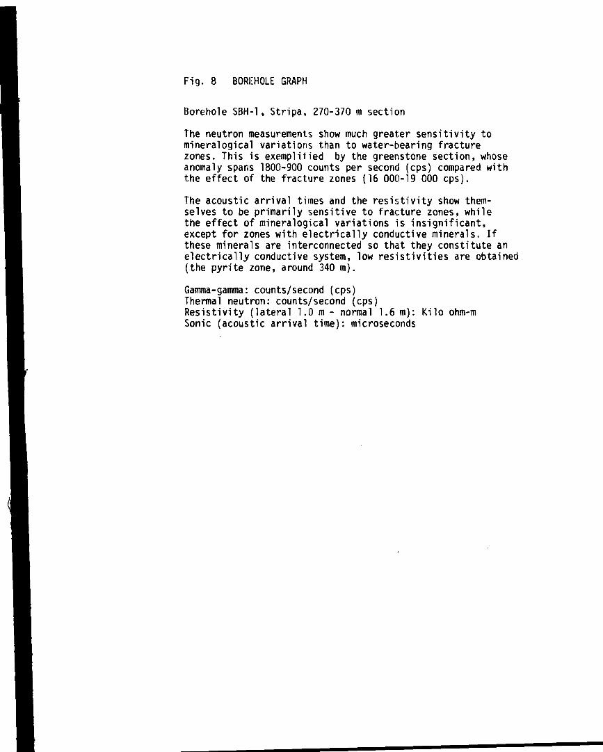
Fig. 8 BORCHOLE GRAPH
Borehole SBH-1, Stripa, 270-370 m section
The neutron measurements show much greater sensitivity tomineralogical variations than to water-bearing fracturezones. This is exemplified by the greenstone section, whoseanomaly spans 1800-900 counts per second (cps) compared withthe effect of the fracture zones (16 000-19 000 cps).
The acoustic arrival times and the resistivity show them-selves to be primarily sensitive to fracture zones, whilethe effect of mineralogical variations is insignificant,except for zones with electrically conductive minerals. Ifthese minerals are interconnected so that they constitute anelectrically conductive system, low resistivities are obtained(the pyrite zone, around 340 m).
Gamma-gamma: counts/second (cps)Thermal neutron: counts/second (cps)Resistivity (lateral 1.0 m - normal 1.6 m): Kilo ohm-mSonic (acoustic arrival time): microseconds

NEUTRON
(counts/sec )
SONIC
(/'sec)
RESISTIVITYLat. 1,0m Norm 1,6m
(k ohm m )
Increased density Increased watercontent Increased fracturingIncreased watercontent
«^T GREENSTONE
FRACTURED ROCK
FRACTUREDROCK
Chlorite zone
Fig. 8

TV-granskning. diff.punWIresistans KRÅKEMiLA 1
FRACTURE WIDTH
crushnumber of £ ' - ' " • " - 'fractures I
• is-
Rock
1000 10000 OhmI 1—t I t u m
^ - H i |
' 1
TV inspection, differential point resistance KRÅKEMÄLA 1
5000i
50-1
ZXi
1
Fig. 9 TV INSPECTION AND DIFFERENTIAL RESISTANCE
Borehole K 1, 0-205 m section
Differential resistance is primarily sensitive to variationsin borehole diameter and open fractures The open fracturesin this borehole section are associated with relatively highpermeabilities.
5000 5000I
I i
5000I

10 000
Fig. 10 ACOUSTIC WAVEFORM AND DIFFERENTIAL RESISTANCE
Borehole SBH-1. Stripa 300-330 m section
The acoustic waveform has more character in the right-handpart of the graph, where the shear waves arrive. The diffe-rential resistance shows good agreement with the waveformgraph, except in the section with calcite-healed fractures(305-307 m). This indicates that the waveform graph providesinformation on relatively closed fractures in the boreholewall that are not indicated by differential resistance.

Fig. 11 BOREHOLE GRAPH
Borehole SPH-1, Stripa, 270-370 m section
The differential resistance and the caliper exhibit relativelysimilar readings. These methods are primarily sensitive tovariations in borehole diameter and open fractures. The diffe-rential resistance is also sensitive to fractures filled withelectrically conductive minerals (sulphides), e.g. pyrite(330-355 m). The scale for differential resistance has beenadjusted to the latter, and does not represent the full sensi-tivity of the method.
Caliper: borehole diameter in mm.Differential resistance: ohmSonic (acoustic arrival time): microsecondsResistivity (Lat. 1.6 m, - Norm. 1.6 m): kilo ohm-mPy: pyrite-healed fractures

Slantdepth
CALIPER
(mm)71 76,5 77
DIFFERENTIALRESISTANCE
OHMS
SONIC RESISTIVITY— L a t . 1£m Norni.1£m
(k ohm m)
FRACTUREDROCK
FRACTUREDROCK
Fig. 11

8 h vätskans res(ohm m)
1 2
S P i m V i
. 50
100-
200
300
400
Punktresistans) tohn- )
10c 10-
Resist i vi tet ( N o r m a l ) R « s i s r i v i t i l ( Latera l )(ohmm) (or f)
BorrhiMslmyram
'•>)
5 0 0 -•
Depth belowrock surface (m)
Fig. 12 BOREHOLE GRAPH
Borehole Ä 1, Ävrö
The slingram measurements show similar readings for both5 m and 40 m distance between transmitter and receiver.These readings are symmetrical around the receiver. Thisshows that generated signals derive from the immediatevicinity of the receiver.
10: 10"
10V.Re 5 Im
Borehole liquid resistivity: ohm-mSP: MillivoltsPoint resistance: ohm-mResistivity (Normal-1.6 m, — 5 m and "''16 m): ohm-mResistivity (Lateral-1.6 m, — 5.2 and *"* * 16.8 m): ohm-mNatural gamma: microroentgen/hourBorehole slingram 5 m: percent of transmitter fieldBorehole slingram 40 m: percent of transmitter field

Resistivittt LattrnlI ohm tn)
Nafurlig gammar R/t
1 0 0 -
300-
400-
500-
103 10'0 ^-
1 ^
700- - '
Borrhdlstingram
10V.
Re 40 imiO
10%
i R*5 T ImS
I i
Borehole length (m)
Fig. 13 BOREHOLE GRAPH
Borehole K 3, Kråkemåla
At a depth of 600 m, there is a mineralized zone with amarked si ingram and natural gamma anomaly, which has aninsignificant resistivity drop. This indicates that themineralised zone has a favourable geometric relationshipto the borehole.
Resistivity (lateral -1.6, -— 5.2 and 16.8 m): ohm-mNatural gamma: microroentgen/hSI ingram 5 m and 40 m: percent of transmitter field

B h vutsk.res(ohm m)
110*
I
S P ( rr. V Jpr 10mV
100-
2 0 0 -
300
400-
500
i
f
/
i
7i
Tunkfresistans) (ohm
10*» 103
Resist iv i f -eM Normal) Resist tv l tet ( L a t e r a l !(ohm m I (ohm rr
» Vi F
i i .
-5% 0 + 5 %
Ref C
SJ
C-*••£
Depth belowrock surface (m)
Fig. 14 BOREHOLE GRAPH
Borehole Fi 1, Finnsjön
A major VLF anomaly starts at a depth of 330 m. This anomalyprobably indicates connection with the heavy fracture zonePreviously indicated from the ground surface via aerialphotographe interpretation and si ingram indications.
-5% 0 *5%i
Ref. < Im.
Borehole liquid resistivity: ohm-mSP: millivoltsPoint resistance: ohm-mResistivity (normal - 1.6 m — 5 m och '"16 m): ohm-nResistivity (lateral - 1.6 m — 5 m -*- 0.3 m
16.8 m): ohm-mVLF Reall and Imaginary component: percent of incidentprimary field