report on additional geotechnical investigation prepared for
TRANSCRIPT

Report on Additional Geotechnical Investigation
Centre of Excellence in Agricultural Education (CoE) Londonderry Road
Richmond
Prepared for Conrad Gargett Pty Ltd
HASH-00-SD-GT-RP-0001
Project 85644.02 April 2021

Document History
Document details
Project No. 85644.02 Document No. R.001
Document title Report on Additional Geotechnical Investigation
Centre of Excellence in Agricultural Education (CoE)
Site address Londonderry Road, Richmond
Report prepared for Conrad Gargett Pty Ltd
File name 85644.02.R.001.Rev2.Additional Richmond Geotech
Document status and review
Revision Prepared by Reviewed by Date issued
Revision 0 P Oitmaa S Easton 20 September 2017
Revision 1 P Oitmaa S Easton 12 January 2018
Revision 2 P Oitmaa S Easton 26 April 2021
Distribution of copies
Revision Electronic Paper Issued to
Revision 0 1 Conrad Gargett Pty Ltd
Revision 1 1 Conrad Gargett Pty Ltd
Revision 2 1 Conrad Gargett Pty Ltd
The undersigned, on behalf of Douglas Partners Pty Ltd, confirm that this document and all attached
drawings, logs and test results have been checked and reviewed for errors, omissions and inaccuracies.
Signature Date
Author
26 April 2021
Reviewer
26 April 2021
Douglas Partners Pty Ltd
ABN 75 053 980 117
www.douglaspartners.com.au
96 Hermitage Road
West Ryde NSW 2114
PO Box 472
West Ryde NSW 1685
Phone (02) 9809 0666
Fax (02) 9809 4095

Additional Geotechnical Investigation, Centre of Excellence in Agricultural Education (CoE) 85644.02.R.001.Rev2 Londonderry Road, Richmond Apr 2021
Table of Contents
Page
1. Introduction ................................................................................................................... 1
2. Site Description ............................................................................................................ 2
3. Regional Geology and Hydrogeology ............................................................................ 2
4. Previous Field Work ...................................................................................................... 3
4.1 Methods ............................................................................................................... 3
4.2 Results ................................................................................................................ 4
5. Current Field Work ........................................................................................................ 4
5.1 Methods ............................................................................................................... 4
5.2 Results ................................................................................................................ 5
6. Laboratory Testing ........................................................................................................ 6
7. Geotechnical Model ...................................................................................................... 7
8. Proposed Development ................................................................................................ 7
9. Comments .................................................................................................................... 8
9.1 Site Classification ................................................................................................ 8
9.2 Site Preparation ................................................................................................... 8
9.3 Excavation ........................................................................................................... 9
9.4 Excavation Support.............................................................................................. 9
9.5 Groundwater ...................................................................................................... 10
9.6 Foundations ....................................................................................................... 10
9.7 Pavements ........................................................................................................ 12
9.8 Aggressivity ....................................................................................................... 12
9.9 Seismicity .......................................................................................................... 12
10. Limitations .................................................................................................................. 12
Appendix A: About this Report
Appendix B: Drawing
Appendix C: Current Field Work Results
Appendix D: Previous Field Work Results
Appendix E: Laboratory Test Results

Page 1 of 13
Additional Geotechnical Investigation, Centre of Excellence in Agricultural Education (CoE) 85644.02.R.001.Rev2 Londonderry Road, Richmond Apr 2021
Report on Additional Geotechnical Investigation
Centre of Excellence in Agricultural Education (CoE)
Londonderry Road, Richmond
1. Introduction
This report presents the results of geotechnical investigations undertaken for the proposed Centre of
Excellence in Agricultural Education (CoE) off Londonderry Road, Richmond. The work was
commissioned by Conrad Gargett Pty Ltd, architects.
The proposed development involves the construction and operation of a new Centre of Excellence (CoE)
in Agricultural Education on a leased land parcel within the Western Sydney University (Hawkesbury
Campus) site, Richmond NSW.
The CoE will provide new agricultural / STEM teaching facilities with general learning and administration
spaces to be utilised by rural, regional, metropolitan and international school students. The CoE will
accommodate up to 325 students and up to 32 employees consisting of farm assistants, administration
staff and teachers and up to eleven (11) itinerant staff members. The CoE will also include short-term
on-site accommodation facilities for up to 62 visiting students and teaching professionals from regional
and rural NSW.
The CoE will include five science laboratories, ten general learning spaces, practical activity teaching
areas, seminar, botany room, administration block and accommodation facilities. It will also include
covered outdoor learning areas, dining / recreation hall, canteen and kitchen, agricultural plots,
significant landscaping spaces, car parking and provision of necessary infrastructure.
The proposed development has been designed to be well integrated into the Western Sydney University
site, having due regard for scale, bulk and orientation of existing buildings. The educational facilities
will display linear open building forms in single story design with open spaces and lightweight
construction techniques. The site is benefitted by Blue Mountains views to the west and the building
and landscape plans have incorporated viewing opportunities into the design.
Refer to Figure 1 below for the proposed Site Plan.

Page 2 of 13
Additional Geotechnical Investigation, Centre of Excellence in Agricultural Education (CoE) 85644.02.R.001.Rev2 Londonderry Road, Richmond Apr 2021
Figure 1: Proposed Site Plan
2. Site Description
The redevelopment site is located to the south-west of the main Western Sydney University buildings
on part of Lot 2 DP 1051798. The site is approximately 18 ha in area. It is bounded by Western Sydney
University and an aged-care facility to the north, land used largely for agricultural purposes to the east
and south, and Londonderry Road to the west. The ground surface on the site slopes very gently
downwards to south-east; surface levels vary between about RL 23.5 m and RL 22.5 m AHD.
At the time of the investigation the site was divided into paddocks with very few improvements. A number
of drainage swales were located between the paddocks. The surface was generally well-grassed and
some trees were present along the southern boundary as well as scattered sparingly elsewhere on the
site.
The location of the site is shown on Drawing 1 in Appendix B.
3. Regional Geology and Hydrogeology
The Penrith 1:100 000 Geological Series Sheet indicates that the site is underlain by the Tertiary-aged
Londonderry Clay which comprises clay with patches of cemented, consolidated sand. The area to the

Page 3 of 13
Additional Geotechnical Investigation, Centre of Excellence in Agricultural Education (CoE) 85644.02.R.001.Rev2 Londonderry Road, Richmond Apr 2021
north is shown as being underlain by the Quaternary-aged Clarendon Formation which comprises clay,
clayey sand and silt. An extract from the geological map is shown in Figure 2.
Figure 2: Extract from geological map
The topography of the site suggests that groundwater may be shallow and possibly a beneficial resource
in sandy zones of the aquifer.
4. Previous Field Work
4.1 Methods
The field work for the combined geotechnical and contamination investigation included the drilling of
11 boreholes to depths of 7.5 m at the locations shown on Drawing 1 in Appendix B. All boreholes were
drilled using solid flight augers. Standard penetration tests (SPTs) were undertaken at regular depth
intervals and all field work was supervised on site by a geotechnical engineer.
The ground surface levels at the bores (to AHD) were interpolated from a survey plan using coordinates
measured using a differential global positioning system (dGPS) receiver.
LONDONDERRY
CLAY
SITE
CLARENDON FORMATION

Page 4 of 13
Additional Geotechnical Investigation, Centre of Excellence in Agricultural Education (CoE) 85644.02.R.001.Rev2 Londonderry Road, Richmond Apr 2021
4.2 Results
The subsurface conditions encountered in the previous boreholes are presented in the borehole logs in
Appendix D. Notes defining descriptive terms and classification methods are included in Appendix A.
The boreholes encountered the following materials:
• Topsoil (typically silty sand with rootlets, gravel) to depths of between 0.1 m and 0.9 m; underlain
by
• Filling in BH6 only (silty sand with gravel, plastic bags, rags, plastic bottles) to a depth of 2.5 m;
underlain by
• Sands (medium dense to very dense silty sand, clayey sand, clayey silty sand) to depths of between
3.9 m and 4.8 m; underlain by
• Clays (stiff to very stiff silty clay, sandy silty clay, sandy silt) to the base of the bores at 7.5 m depth.
Free groundwater was observed at depths of between 0.3 m and 2.5 m in all bores except BH2 and BH3
which were dry at the completion of drilling.
Table 1 summarises the levels at which different materials were encountered in the boreholes.
Table 1: Summary of Material Strata Levels in Boreholes
Stratum RL of Top of Stratum (m, AHD)
BH1 BH2 BH3 BH4 BH5 BH6 BH7 BH8 BH9 BH10 BH11
Ground Surface 23.4 23.2 23.0 23.3 23.2 23.3 23.0 22.9 23.0 23.8 22.9
Filling NE NE NE NE NE 20.8 NE NE NE NE NE
Sands 23.1 23.0 22.5 23.0 23.0 20.8 22.9 22.6 22.1 23.3 22.7
Clays 19.4 19.2 19.0 19.3 18.4 19.3 19.1 18.9 19.0 19.5 18.7
Base of Borehole 15.9 15.7 15.5 15.8 15.7 15.8 15.5 15.4 15.5 16.3 15.4
Notes: NE = not encountered
5. Current Field Work
5.1 Methods
Six cone penetration tests (CPTs 101 to 106) were undertaken to depths of between 17.2 m and 19.1 m
at the locations shown on Drawing 1 in Appendix B. A CPT involves pushing a 35 mm diameter
instrumented cone and friction sleeve into the ground using a ballasted truck-mounted testing rig.
Measurements of cone resistance and sleeve friction are made at 20 mm depth intervals and are stored
on a portable computer for subsequent interpretation.
Seven test pits (TP107 to TP113) were excavated to depths of between 1.1 m and 1.4 m at the locations
shown on Drawing 1 in Appendix B. The purpose of these pits was to obtain bulk soil samples for

Page 5 of 13
Additional Geotechnical Investigation, Centre of Excellence in Agricultural Education (CoE) 85644.02.R.001.Rev2 Londonderry Road, Richmond Apr 2021
laboratory testing (TP107 and TP108) and to delineate an area around the previous borehole BH6 in
which uncontrolled filling was encountered (TP109 to TP113).
The ground surface levels at the bores (to AHD) were interpolated from a survey plan using coordinates
measured using a differential global positioning system (dGPS) receiver.
5.2 Results
The subsurface conditions encountered in the current CPTs and test pits are presented in the results
sheets and logs in Appendix C. Notes defining descriptive terms and classification methods are included
in Appendix A.
The materials interpreted from the CPTs can be described as follows:
• Sand/Silty Sand (very loose to loose) to depths of between 0.8 m and 1.4 m; underlain by
• Clay/Silty Clay (very stiff to hard) interbedded with Clayey Sand/Silty Sand (medium dense to very
dense) to the base of the CPTs at depths of between 17.2 m and 19.1 m.
Refusal of the CPT equipment is likely to have occurred in very dense gravels and/or weathered
bedrock. Deep cored boreholes would be required to confirm the actual depths to bedrock.
Groundwater was observed in only two CPTs: CPT101 at 2.0 m depth (RL 20.9 m AHD) and CPT105
at 7.8 m depth (RL 15.4 m AHD). Water was not measured within 10 m of the ground surface at the
remaining CPT locations. No long term monitoring of groundwater levels has been carried out.
Table 2 summarises the levels at which different materials were inferred from the CPTs.
Table 2: Summary of Material Strata Levels in CPTs
Stratum RL of Top of Stratum (m, AHD)
CPT101 CPT102 CPT103 CPT104 CPT105 CPT106
Ground
Surface 22.9 23.0 23.0 22.9 23.2 23.0
vl to l
Sands 22.9 23.0 23.0 22.9 23.2 23.0
vst to h Clays &
md to d Sands 21.6 21.6 22.2 21.9 22.0 21.8
Base of
Test 3.8 4.5 5.8 5.4 4.5 5.3
Notes: vl = very loose; l = loose; md = medium dense; d = dense; vst = very stiff; h = hard

Page 6 of 13
Additional Geotechnical Investigation, Centre of Excellence in Agricultural Education (CoE) 85644.02.R.001.Rev2 Londonderry Road, Richmond Apr 2021
The materials encountered in the test pits can be described as follows:
• Filling consisting of sands with varying proportions of rootlets, gravel, building rubble (concrete,
brick, plastic, wood, rubber, metal wire, a metal drum) to depths of between 0.2 m and 1.2 m. The
building rubble was encountered in TP109, TP110 and TP 111 only; underlain by
• Clayey Sand (possible filling) to the base of the pits at depths of between 1.1 m and 1.4 m.
Groundwater was observed in only one test pit: TP107 at 0.9 m depth (RL 22.0 m AHD). Water was not
observed at the remaining test pit locations.
6. Laboratory Testing
Selected soil samples were analysed for California bearing ratio (CBR), Atterberg Limits (plasticity) and
aggressivity (electrical conductivity, pH, chloride and sulphate). The results are summarised in Tables 3
and 4. The detailed results are included in Appendix E.
Table 3: Summary of Laboratory Test Results for CBR and Atterberg Limits
Sample/
Depth (m) Description
CBR
(%)*
Swell
(%)
MDD
(t/m3)
WP
(%)
WL
(%)
PI
(%)
LS
(%)
BH1/0-1.5 Silty sand 30 -0.5 2.06 - - - -
BH2/4.0-4.36 Silty clay - - - 16 30 14 9.5
BH3/4.0-4.95 Silty clay - - - 12 29 17 11.0
BH5/0.2-1.0 Silty sand 25 -0.5 1.91 - - - -
BH7/4.0-4.95 Silty clay - - - 14 41 27 14.0
BH8/0.1-1.0 Silty sand 11 -0.5 1.93 - - - -
BH11/0-1.0 Silty sand 20 -0.5 1.89 - - - -
BH11/5.5-5.95 Silty clay - - - 14 42 28 17.5
TP107/1.0-1.2 Silty sand 7 -0.5 2.07 - - - -
TP108/1.0-1.1 Silty sand 7 -0.5 1.98 - - - -
Notes: *4-day soak, 4.5 kg surcharge, 100% Standard compaction; MDD = maximum dry density; WP = plastic limit;
WL = liquid limit; PI = plasticity index; LS = linear shrinkage

Page 7 of 13
Additional Geotechnical Investigation, Centre of Excellence in Agricultural Education (CoE) 85644.02.R.001.Rev2 Londonderry Road, Richmond Apr 2021
Table 4: Summary of Laboratory Test Results for Aggressivity
Sample/
Depth (m) Description pH* EC (S/cm)*
Chloride
(mg/kg)*
Sulphate
(mg/kg)*
BH3/7.0-7.45 Silty clay 6.7 350 390 58
BH5/0.5 Silty sand 6.8 25 <10 <10
BH7/2.5-2.95 Clayey sand 6.9 35 10 10
BH9/0.1 Topsoil 5.6 23 <10 <10
Notes: *Sample mixed 1(soil):5(water) prior to testing
7. Geotechnical Model
The site appears to be underlain by very loose to loose topsoil/filling to depths in the order of 1 m to
1.5 m, and uncontrolled filling including building rubble in the vicinity of BH6. The possible extent of the
filling that includes building rubble, based on the test pit results, is shown on Drawing 1 in Appendix B.
The filling is underlain by alluvial soils which comprise very stiff to hard clays/silty clays and medium
dense to very dense clayey sands/silty sands. The alluvium appears to be present to depths in the order
of 17 m to 19 m in the area of the CPTs, and is likely to be underlain by either gravels or weathered
bedrock.
The laboratory testing programme indicates that the clays are highly plastic and of moderate to high
reactivity. The CBR results show that the near-surface sandy filling is of reasonable strength when
compacted. The aggressivity testing indicates non-aggressive conditions.
Groundwater was observed at depths of between 0.3 m and 2.5 m in some areas of the site, 7.8 m in
CPT105, and was not observed within 10 m of the surface in others. This indicates that perched water
exists within the soils and that the regional groundwater table is deeper than observed. Long term
monitoring would be required to confirm levels if this is important (e.g. for basements).
8. Proposed Development
The CoE will include five science laboratories, ten general learning spaces, practical activity teaching
areas, seminar, botany room, administration block and accommodation facilities. It will also include
covered outdoor learning areas, dining / recreation hall, canteen and kitchen, agricultural plots,
significant landscaping spaces, car parking and provision of necessary infrastructure. We have
assumed that the new buildings will comprise one and two-storey structures with relatively high column
loads due to the spans required. Pavement areas will typically surround the new buildings.
The geotechnical issues considered relevant to the proposed development include site classification,
site preparation, excavation, excavation support, groundwater, foundations and pavements. Comments
on seismicity and aggressivity are also provided.

Page 8 of 13
Additional Geotechnical Investigation, Centre of Excellence in Agricultural Education (CoE) 85644.02.R.001.Rev2 Londonderry Road, Richmond Apr 2021
9. Comments
9.1 Site Classification
The natural sandy soils in the upper 4 m of the site are expected to be largely non-plastic and therefore
experience only slight movements due to changes in moisture content. As such, a site classification of
Class S would be appropriate for the natural medium dense sands and re-worked non-reactive filling if
footings are to be designed in accordance with Australian Standard AS 2870 – 2011 Residential slabs
and footings. Class S sites may experience unrestrained, free-surface movements of between 0 mm
and 20 mm as a result of changes in moisture content.
Areas on the site in which more than 0.4 m of filling is present, and areas in which very loose to loose
sand remains, would be classified as Class P. These areas will require re-working prior to re-
classification if the footings are to be designed in accordance with AS 2870 – 2011.
9.2 Site Preparation
Any existing filling that is required to support structures and pavements will need to be reworked to
reduce the potential for unacceptable settlements associated with poorly or variable compacted filling.
New filling will also need to be placed in accordance with an engineering specification. The following
procedure could be followed during earthworks activities:
• Strip organic-rich topsoil from areas of the site in which filling, structures and/or pavements are
proposed. A nominal depth of 100 mm would be appropriate but confirmation of this will need to be
made on site at the commencement of construction;
• Excavate existing filling in areas of the site in which filling, structures and/or pavements are
proposed;
• Compact the exposed surface and proof-roll using a roller of 10 t deadweight (or equivalent) in the
presence of a geotechnical engineer. Any areas exhibiting unacceptable movements during the
proof-roll may require further rectification;
• Place suitable filling in maximum 250 mm thick layers and compact to achieve a dry density ratio of
between 98% and 102% relative to Standard compaction. The upper 0.5 m of pavement subgrade
areas should be compacted to achieve a dry density ratio of between 100% and 102% relative to
Standard compaction;
• The moisture content should be within 2% of the Standard optimum moisture content of the material
if it exhibits clay-like properties;
• A layer of granular product (e.g. roadbase, recycled crushed concrete etc.) should be considered
as the top layer of filling to improve trafficability on site, particularly during and following periods of
wet weather;
• Density testing should be undertaken in accordance with the requirements of AS 3798 – 2007
Guidelines on earthworks for commercial and residential developments.
If filling is imported to the site then the engineering properties (e.g. plasticity, reactivity, CBR etc.) should
ideally be equivalent, or superior, to the existing materials on the site.

Page 9 of 13
Additional Geotechnical Investigation, Centre of Excellence in Agricultural Education (CoE) 85644.02.R.001.Rev2 Londonderry Road, Richmond Apr 2021
It is noted that trafficability on the site could provide problematic where perched groundwater is close to
the surface. The placement of granular surface materials, in conjunction with localised dewatering or
drainage, should help to alleviate these issues. The near-surface sandy soils are also likely to prove
challenging for rubber-tyred vehicles without some form of granular confinement.
9.3 Excavation
Excavation during earthworks and construction is expected to be required in filling and sandy soils. This
should be readily achievable using conventional earthmoving equipment such as hydraulic excavators
with bucket attachments, scrapers and dozers. Excavation in rock will not be required.
It should be noted that any off-site disposal of spoil will generally require assessment for re-use or
classification in accordance with current Waste Classification Guidelines (NSW EPA, 2014).
9.4 Excavation Support
Vertical excavations in filling and sandy soils are not expected to be stable. Temporary batters of
1.5(H):1(V) could be used to support the sides of excavations up to 3 m deep above the perched
groundwater. Flatter batters and/or dewatering will be required for excavations below groundwater.
Permanent batters for excavations and embankments should be no steeper than 2(H):1(V) and possibly
flatter where vegetation maintenance is required. Erosion protection should be provided for all
permanent batters.
Surcharge loads should be placed no closer to the crest of the batter than a distance equal to the vertical
height of the batter, unless specific stability analysis shows that the loads can be placed closer.
Retaining walls (if required) could be designed using the parameters provided in Table 5.
Table 5: Material and Strength Parameters for Retaining Walls
Material Bulk Density (kN/m3) Coefficient of Active
Earth Pressure (Ka)
Ultimate Passive Earth
Pressure1
Filling 20 0.40 -
Medium Dense Sand 20 0.30 Kp = 3.3
Dense Sand 20 0.25 Kp = 3.8
Stiff to Very Stiff Clay 20 0.30 200 kPa
Hard Clay 20 0.25 300 kPa
Notes: 1Minimum of 0.5 m embedment should be provided

Page 10 of 13
Additional Geotechnical Investigation, Centre of Excellence in Agricultural Education (CoE) 85644.02.R.001.Rev2 Londonderry Road, Richmond Apr 2021
A triangular lateral earth pressure distribution could be assumed for cantilevered walls or walls with a
single row of support. Lateral pressures due to surcharge loads from adjacent buildings, sloping ground
surface, pavements and construction machinery should be included where relevant. Hydrostatic
pressure acting on retaining walls should also be included in the design where adequate drainage is not
provided behind the full height of the walls.
9.5 Groundwater
Groundwater was encountered at relatively shallow depths in some areas of the site and was not
observed to depths of up to 10 m in others. It is therefore likely that these observations were perched
groundwater rather than the regional aquifer. Nevertheless, excavations below the existing surface
levels may encounter water that needs to be removed by dewatering or other drainage measures.
Dewatering may require the use of spear points and/or wells in highly permeable sandy soils, or possibly
submersible pumps in sump pits where the soils have a sufficient clay content to effectively reduce their
permeability.
Due to the sandy nature of the near-surface soils, any sub-surface structures should be tanked
(i.e. designed to be watertight) to prevent groundwater ingress.
9.6 Foundations
Spread footings (i.e. pad or strip footings) may be suitable for supporting lightly loaded structures and
could be designed on the basis of the preliminary allowable bearing pressure parameters provided in
Table 6. Specific analysis should be undertaken once the columns loads have been determined as
bearing capacity is a function of footing width and depth in cohesionless soils. Spread footings may
undergo settlements in the order of 1% of the footing width and therefore large footings required to
support relatively high column loads would be expected to undergo significant settlements.
It should be noted that soil movements caused by moisture variations should be considered in the design
of spread footings; further advice is provided on this issue in Section 9.1 of this report.
Table 6: Preliminary Design Parameters for Spread Footings
Material Description
Allowable Bearing
Pressure Above
Groundwater1 (kPa)
Allowable Bearing
Pressure Within
Groundwater (kPa)
Young’s Modulus
(MPa)
Engineered Filling 100 50 20
Medium Dense Sands 250 150 30
Dense Sands 350 200 50
Note: These parameters are based on 600 mm wide footings founded at a depth of at least 500 mm
1Base of footing at least 2 x footing width above groundwater
Stiffened raft slabs could also be considered to reduce settlements between columns and additional
information can be provided on this if such slabs are proposed.

Page 11 of 13
Additional Geotechnical Investigation, Centre of Excellence in Agricultural Education (CoE) 85644.02.R.001.Rev2 Londonderry Road, Richmond Apr 2021
Alternatively, cased bored piles, continuous flight auger (CFA) piles or steel screw piles could be used
to support structural loads and could be proportioned on the basis of the design parameters provided in
Table 7.
Table 7: Design Parameters for Cased Bored, CFA and Steel Screw Piles
Material
Description
Allowable
End-Bearing
Pressure
(kPa)
Allowable
Shaft
Adhesion1
(kPa)
Ultimate End-
Bearing
Pressure
(kPa)
Ultimate
Shaft
Adhesion1
(kPa)
Young’s
Modulus
(MPa)
Engineered
Filling 150 15 450 30 20
Medium Dense
Sands 300 20 900 50 30
Dense
Sands 1000 75 3000 150 50
Stiff to Very Stiff
Clays 300 20 900 50 20
Gravels/
Weathered Rock 1000 75 3000 150 100
Notes: 1Only below 1 m depth and only for CFA piles (not cased bored piles or steel screw piles)
A geotechnical strength reduction factor (g) should be applied to the ultimate values provided in Table 7
if the limit-state design process is undertaken to design the piles. Australian Standard AS 2159 – 2009
Piling – Design and installation provides information on how to determine an appropriate value of g
which is based on a risk assessment. The pile designer will need to confirm a g value when the piling
contractor is selected, however it is suggested that a preliminary value of 0.50 be adopted at this stage.
Settlement of a pile is dependent on the loads applied to the pile and the foundation conditions in the
socket zone and below the pile toe. The total settlement of a pile designed using the allowable
parameters provided in this report should be less than 1% of the pile diameter upon application of the
design load. Serviceability analysis should be undertaken if the ultimate bearing pressures
(incorporating a suitable reduction factor) are used to proportion the piles.
All bored piles should be inspected by an experienced geotechnical professional during construction to
check the adequacy of the foundation material and to check the socket cleanliness. It is noted that a
tremie system may need to be used where groundwater in intercepted in the pile holes. Acceptance of
piles installed using ‘blind’ techniques (i.e. CFA piles and steel screw piles) usually requires some form
of load testing and rig-gauge calibration.
Driven piles would also be suitable on this site from an engineering perspective, however the noise and
vibration impacts on Western Sydney University and other nearby facilities would need to be considered.

Page 12 of 13
Additional Geotechnical Investigation, Centre of Excellence in Agricultural Education (CoE) 85644.02.R.001.Rev2 Londonderry Road, Richmond Apr 2021
9.7 Pavements
The CBR results show that the sands will provide good support for the pavement once the pavement
layers provide some confinement. A design CBR of 10% is considered suitable, with sensitivity analysis
undertaken for a CBR of 7% which was the lowest recorded result in the laboratory. Any weaker areas
of subgrade (if encountered) may require improvement during construction. The CBR of any imported
filling should also be assessed to confirm this suggested design value is appropriate.
A total pavement thickness of 250 mm incorporating both granular (DGB20) and asphalt layers is
considered appropriate for carparks that will be used by light passenger vehicles only (i.e. less than 2 t
GVM). For example, the profile could comprise 250 mm of DGB20 and a bitumen seal or 200 mm of
DGB20 and 50 mm of asphalt.
The pavement thickness of roads, and carparks that will be used by heavier vehicles, should be
designed on the basis of the anticipated traffic loading, design life and performance requirements.
The subgrade should be prepared in accordance with Section 9.2 of this report. The granular pavement
layer(s) should be compacted to achieve a dry density ratio of at least 98% relative to Modified
compaction.
Suitable cross-fall and drainage should be provided to reduce the risk of the subgrade becoming
saturated during the life of the pavement.
9.8 Aggressivity
The laboratory test results indicate that the samples tested are non-aggressive to buried concrete and
steel elements in accordance with the provisions of Australian Standard AS 2159 – 2009 Piling – Design
and installation.
9.9 Seismicity
A Hazard Factor (Z) of 0.08 would be appropriate for the development site in accordance with Australian
Standard AS 1170.4 – 2007 Structural design actions – Part 4: Earthquake actions in Australia. The
site sub-soil class would be Class Ce.
10. Limitations
Douglas Partners Pty Ltd (DP) has prepared this report for the proposed Centre of Excellence in
Agricultural Education (CoE) campus, Londonderry Road, Richmond, in accordance with DP's proposals
dated 27 July 2016 and 7 August 2017, and subsequent acceptance received from Conrad Gargett Pty
Ltd. The report is provided for the use of Conrad Gargett Pty Ltd for this project only and for the
purpose(s) described in the report. It should not be used for other projects or by a third party.

Page 13 of 13
Additional Geotechnical Investigation, Centre of Excellence in Agricultural Education (CoE) 85644.02.R.001.Rev2 Londonderry Road, Richmond Apr 2021
The results provided in the report are indicative of the sub-surface conditions only at the specific
sampling or testing locations, and then only to the depths investigated and at the time the work was
carried out. Subsurface conditions can change abruptly due to variable geological processes and also
as a result of anthropogenic influences. Such changes may occur after DP's field testing has been
completed. In preparing this report DP has necessarily relied upon information provided by the client
and/or their agents.
This report must be read in conjunction with all of the attached notes and should be kept in its entirety
without separation of individual pages or sections. DP cannot be held responsible for interpretations or
conclusions made by others unless they are supported by an expressed statement, interpretation,
outcome or conclusion given in this report.
This report, or sections from this report, should not be used as part of a specification for a project, without
review and agreement by DP. This is because this report has been written as advice and opinion rather
than instructions for construction.
The contents of this report do not constitute formal design components such as are required, by the
Health and Safety Legislation and Regulations, to be included in a Safety Report specifying the hazards
likely to be encountered during construction and the controls required to mitigate risk.
Douglas Partners Pty Ltd

Appendix A
About this Report

July 2010
Introduction These notes have been provided to amplify DP's
report in regard to classification methods, field
procedures and the comments section. Not all are
necessarily relevant to all reports.
DP's reports are based on information gained from
limited subsurface excavations and sampling,
supplemented by knowledge of local geology and
experience. For this reason, they must be
regarded as interpretive rather than factual
documents, limited to some extent by the scope of
information on which they rely.
Copyright This report is the property of Douglas Partners Pty
Ltd. The report may only be used for the purpose
for which it was commissioned and in accordance
with the Conditions of Engagement for the
commission supplied at the time of proposal.
Unauthorised use of this report in any form
whatsoever is prohibited.
Borehole and Test Pit Logs The borehole and test pit logs presented in this
report are an engineering and/or geological
interpretation of the subsurface conditions, and
their reliability will depend to some extent on
frequency of sampling and the method of drilling or
excavation. Ideally, continuous undisturbed
sampling or core drilling will provide the most
reliable assessment, but this is not always
practicable or possible to justify on economic
grounds. In any case the boreholes and test pits
represent only a very small sample of the total
subsurface profile.
Interpretation of the information and its application
to design and construction should therefore take
into account the spacing of boreholes or pits, the
frequency of sampling, and the possibility of other
than 'straight line' variations between the test
locations.
Groundwater Where groundwater levels are measured in
boreholes there are several potential problems,
namely:
• In low permeability soils groundwater may
enter the hole very slowly or perhaps not at all
during the time the hole is left open;
• A localised, perched water table may lead to
an erroneous indication of the true water
table;
• Water table levels will vary from time to time
with seasons or recent weather changes.
They may not be the same at the time of
construction as are indicated in the report;
and
• The use of water or mud as a drilling fluid will
mask any groundwater inflow. Water has to
be blown out of the hole and drilling mud must
first be washed out of the hole if water
measurements are to be made.
More reliable measurements can be made by
installing standpipes which are read at intervals
over several days, or perhaps weeks for low
permeability soils. Piezometers, sealed in a
particular stratum, may be advisable in low
permeability soils or where there may be
interference from a perched water table.
Reports The report has been prepared by qualified
personnel, is based on the information obtained
from field and laboratory testing, and has been
undertaken to current engineering standards of
interpretation and analysis. Where the report has
been prepared for a specific design proposal, the
information and interpretation may not be relevant
if the design proposal is changed. If this happens,
DP will be pleased to review the report and the
sufficiency of the investigation work.
Every care is taken with the report as it relates to
interpretation of subsurface conditions, discussion
of geotechnical and environmental aspects, and
recommendations or suggestions for design and
construction. However, DP cannot always
anticipate or assume responsibility for:
• Unexpected variations in ground conditions.
The potential for this will depend partly on
borehole or pit spacing and sampling
frequency;
• Changes in policy or interpretations of policy
by statutory authorities; or
• The actions of contractors responding to
commercial pressures.
If these occur, DP will be pleased to assist with
investigations or advice to resolve the matter.

July 2010
Site Anomalies In the event that conditions encountered on site
during construction appear to vary from those
which were expected from the information
contained in the report, DP requests that it be
immediately notified. Most problems are much
more readily resolved when conditions are
exposed rather than at some later stage, well after
the event.
Information for Contractual Purposes Where information obtained from this report is
provided for tendering purposes, it is
recommended that all information, including the
written report and discussion, be made available.
In circumstances where the discussion or
comments section is not relevant to the contractual
situation, it may be appropriate to prepare a
specially edited document. DP would be pleased
to assist in this regard and/or to make additional
report copies available for contract purposes at a
nominal charge.
Site Inspection The company will always be pleased to provide
engineering inspection services for geotechnical
and environmental aspects of work to which this
report is related. This could range from a site visit
to confirm that conditions exposed are as
expected, to full time engineering presence on
site.

July 2010
Sampling Sampling is carried out during drilling or test pitting
to allow engineering examination (and laboratory
testing where required) of the soil or rock.
Disturbed samples taken during drilling provide
information on colour, type, inclusions and,
depending upon the degree of disturbance, some
information on strength and structure.
Undisturbed samples are taken by pushing a thin-
walled sample tube into the soil and withdrawing it
to obtain a sample of the soil in a relatively
undisturbed state. Such samples yield information
on structure and strength, and are necessary for
laboratory determination of shear strength and
compressibility. Undisturbed sampling is generally
effective only in cohesive soils.
Test Pits Test pits are usually excavated with a backhoe or
an excavator, allowing close examination of the in-
situ soil if it is safe to enter into the pit. The depth
of excavation is limited to about 3 m for a backhoe
and up to 6 m for a large excavator. A potential
disadvantage of this investigation method is the
larger area of disturbance to the site.
Large Diameter Augers Boreholes can be drilled using a rotating plate or
short spiral auger, generally 300 mm or larger in
diameter commonly mounted on a standard piling
rig. The cuttings are returned to the surface at
intervals (generally not more than 0.5 m) and are
disturbed but usually unchanged in moisture
content. Identification of soil strata is generally
much more reliable than with continuous spiral
flight augers, and is usually supplemented by
occasional undisturbed tube samples.
Continuous Spiral Flight Augers The borehole is advanced using 90-115 mm
diameter continuous spiral flight augers which are
withdrawn at intervals to allow sampling or in-situ
testing. This is a relatively economical means of
drilling in clays and sands above the water table.
Samples are returned to the surface, or may be
collected after withdrawal of the auger flights, but
they are disturbed and may be mixed with soils
from the sides of the hole. Information from the
drilling (as distinct from specific sampling by SPTs
or undisturbed samples) is of relatively low
reliability, due to the remoulding, possible mixing
or softening of samples by groundwater.
Non-core Rotary Drilling The borehole is advanced using a rotary bit, with
water or drilling mud being pumped down the drill
rods and returned up the annulus, carrying the drill
cuttings. Only major changes in stratification can
be determined from the cuttings, together with
some information from the rate of penetration.
Where drilling mud is used this can mask the
cuttings and reliable identification is only possible
from separate sampling such as SPTs.
Continuous Core Drilling A continuous core sample can be obtained using a
diamond tipped core barrel, usually with a 50 mm
internal diameter. Provided full core recovery is
achieved (which is not always possible in weak
rocks and granular soils), this technique provides a
very reliable method of investigation.
Standard Penetration Tests Standard penetration tests (SPT) are used as a
means of estimating the density or strength of soils
and also of obtaining a relatively undisturbed
sample. The test procedure is described in
Australian Standard 1289, Methods of Testing
Soils for Engineering Purposes - Test 6.3.1.
The test is carried out in a borehole by driving a 50
mm diameter split sample tube under the impact of
a 63 kg hammer with a free fall of 760 mm. It is
normal for the tube to be driven in three
successive 150 mm increments and the 'N' value
is taken as the number of blows for the last 300
mm. In dense sands, very hard clays or weak
rock, the full 450 mm penetration may not be
practicable and the test is discontinued.
The test results are reported in the following form.
• In the case where full penetration is obtained
with successive blow counts for each 150 mm
of, say, 4, 6 and 7 as:
4,6,7
N=13
• In the case where the test is discontinued
before the full penetration depth, say after 15
blows for the first 150 mm and 30 blows for
the next 40 mm as:
15, 30/40 mm

July 2010
The results of the SPT tests can be related
empirically to the engineering properties of the
soils.
Dynamic Cone Penetrometer Tests /
Perth Sand Penetrometer Tests Dynamic penetrometer tests (DCP or PSP) are
carried out by driving a steel rod into the ground
using a standard weight of hammer falling a
specified distance. As the rod penetrates the soil
the number of blows required to penetrate each
successive 150 mm depth are recorded. Normally
there is a depth limitation of 1.2 m, but this may be
extended in certain conditions by the use of
extension rods. Two types of penetrometer are
commonly used.
• Perth sand penetrometer - a 16 mm diameter
flat ended rod is driven using a 9 kg hammer
dropping 600 mm (AS 1289, Test 6.3.3). This
test was developed for testing the density of
sands and is mainly used in granular soils and
filling.
• Cone penetrometer - a 16 mm diameter rod
with a 20 mm diameter cone end is driven
using a 9 kg hammer dropping 510 mm (AS
1289, Test 6.3.2). This test was developed
initially for pavement subgrade investigations,
and correlations of the test results with
California Bearing Ratio have been published
by various road authorities.

May 2019
Description and Classification Methods The methods of description and classification of
soils and rocks used in this report are generally
based on Australian Standard AS1726:2017,
Geotechnical Site Investigations. In general, the
descriptions include strength or density, colour,
structure, soil or rock type and inclusions.
Soil Types Soil types are described according to the
predominant particle size, qualified by the grading
of other particles present:
Type Particle size (mm)
Boulder >200
Cobble 63 - 200
Gravel 2.36 - 63
Sand 0.075 - 2.36
Silt 0.002 - 0.075
Clay <0.002
The sand and gravel sizes can be further
subdivided as follows:
Type Particle size (mm)
Coarse gravel 19 - 63
Medium gravel 6.7 - 19
Fine gravel 2.36 – 6.7
Coarse sand 0.6 - 2.36
Medium sand 0.21 - 0.6
Fine sand 0.075 - 0.21
Definitions of grading terms used are:
Well graded - a good representation of all
particle sizes
Poorly graded - an excess or deficiency of
particular sizes within the specified range
Uniformly graded - an excess of a particular
particle size
Gap graded - a deficiency of a particular
particle size with the range
The proportions of secondary constituents of soils
are described as follows:
In fine grained soils (>35% fines)
Term Proportion
of sand or
gravel
Example
And Specify Clay (60%) and
Sand (40%)
Adjective >30% Sandy Clay
With 15 – 30% Clay with sand
Trace 0 - 15% Clay with trace
sand
In coarse grained soils (>65% coarse)
- with clays or silts
Term Proportion
of fines
Example
And Specify Sand (70%) and
Clay (30%)
Adjective >12% Clayey Sand
With 5 - 12% Sand with clay
Trace 0 - 5% Sand with trace
clay
In coarse grained soils (>65% coarse)
- with coarser fraction
Term Proportion
of coarser
fraction
Example
And Specify Sand (60%) and
Gravel (40%)
Adjective >30% Gravelly Sand
With 15 - 30% Sand with gravel
Trace 0 - 15% Sand with trace
gravel
The presence of cobbles and boulders shall be
specifically noted by beginning the description with
‘Mix of Soil and Cobbles/Boulders’ with the word
order indicating the dominant first and the
proportion of cobbles and boulders described
together.

May 2019
Cohesive Soils Cohesive soils, such as clays, are classified on the
basis of undrained shear strength. The strength
may be measured by laboratory testing, or
estimated by field tests or engineering
examination. The strength terms are defined as
follows:
Description Abbreviation Undrained shear strength
(kPa)
Very soft VS <12
Soft S 12 - 25
Firm F 25 - 50
Stiff St 50 - 100
Very stiff VSt 100 - 200
Hard H >200
Friable Fr -
Cohesionless Soils Cohesionless soils, such as clean sands, are
classified on the basis of relative density, generally
from the results of standard penetration tests
(SPT), cone penetration tests (CPT) or dynamic
penetrometers (PSP). The relative density terms
are given below:
Relative Density
Abbreviation Density Index (%)
Very loose VL <15
Loose L 15-35
Medium dense MD 35-65
Dense D 65-85
Very dense VD >85
Soil Origin It is often difficult to accurately determine the origin
of a soil. Soils can generally be classified as:
Residual soil - derived from in-situ weathering
of the underlying rock;
Extremely weathered material – formed from
in-situ weathering of geological formations.
Has soil strength but retains the structure or
fabric of the parent rock;
Alluvial soil – deposited by streams and rivers;
Estuarine soil – deposited in coastal estuaries;
Marine soil – deposited in a marine
environment;
Lacustrine soil – deposited in freshwater
lakes;
Aeolian soil – carried and deposited by wind;
Colluvial soil – soil and rock debris
transported down slopes by gravity;
Topsoil – mantle of surface soil, often with
high levels of organic material.
Fill – any material which has been moved by
man.
Moisture Condition – Coarse Grained Soils For coarse grained soils the moisture condition
should be described by appearance and feel using
the following terms:
Dry (D) Non-cohesive and free-running.
Moist (M) Soil feels cool, darkened in
colour.
Soil tends to stick together.
Sand forms weak ball but breaks
easily.
Wet (W) Soil feels cool, darkened in
colour.
Soil tends to stick together, free
water forms when handling.
Moisture Condition – Fine Grained Soils For fine grained soils the assessment of moisture
content is relative to their plastic limit or liquid limit,
as follows:
‘Moist, dry of plastic limit’ or ‘w <PL’ (i.e. hard
and friable or powdery).
‘Moist, near plastic limit’ or ‘w ≈ PL (i.e. soil can
be moulded at moisture content approximately
equal to the plastic limit).
‘Moist, wet of plastic limit’ or ‘w >PL’ (i.e. soils
usually weakened and free water forms on the
hands when handling).
‘Wet’ or ‘w ≈LL’ (i.e. near the liquid limit).
‘Wet’ or ‘w >LL’ (i.e. wet of the liquid limit).
May 2017
Introduction These notes summarise abbreviations commonly
used on borehole logs and test pit reports.
Drilling or Excavation Methods C Core drilling
R Rotary drilling
SFA Spiral flight augers
NMLC Diamond core - 52 mm dia
NQ Diamond core - 47 mm dia
HQ Diamond core - 63 mm dia
PQ Diamond core - 81 mm dia
Water Water seep
Water level
Sampling and Testing A Auger sample
B Bulk sample
D Disturbed sample
E Environmental sample
U50 Undisturbed tube sample (50mm)
W Water sample
pp Pocket penetrometer (kPa)
PID Photo ionisation detector
PL Point load strength Is(50) MPa
S Standard Penetration Test
V Shear vane (kPa)
Description of Defects in Rock The abbreviated descriptions of the defects should
be in the following order: Depth, Type, Orientation,
Coating, Shape, Roughness and Other. Drilling
and handling breaks are not usually included on
the logs.
Defect Type
B Bedding plane
Cs Clay seam
Cv Cleavage
Cz Crushed zone
Ds Decomposed seam
F Fault
J Joint
Lam Lamination
Pt Parting
Sz Sheared Zone
V Vein
Orientation
The inclination of defects is always measured from
the perpendicular to the core axis.
h horizontal
v vertical
sh sub-horizontal
sv sub-vertical
Coating or Infilling Term
cln clean
co coating
he healed
inf infilled
stn stained
ti tight
vn veneer
Coating Descriptor
ca calcite
cbs carbonaceous
cly clay
fe iron oxide
mn manganese
slt silty
Shape
cu curved
ir irregular
pl planar
st stepped
un undulating
Roughness
po polished
ro rough
sl slickensided
sm smooth
vr very rough
Other
fg fragmented
bnd band
qtz quartz

May 2017
Graphic Symbols for Soil and Rock General
Soils
Sedimentary Rocks
Metamorphic Rocks
Igneous Rocks
Road base
Filling
Concrete
Asphalt
Topsoil
Peat
Clay
Conglomeratic sandstone
Conglomerate
Boulder conglomerate
Sandstone
Slate, phyllite, schist
Siltstone
Mudstone, claystone, shale
Coal
Limestone
Porphyry
Cobbles, boulders
Sandy gravel
Laminite
Silty sand
Clayey sand
Silty clay
Sandy clay
Gravelly clay
Shaly clay
Silt
Clayey silt
Sandy silt
Sand
Gravel
Talus
Gneiss
Quartzite
Dolerite, basalt, andesite
Granite
Tuff, breccia
Dacite, epidote

July 2010
Introduction The Cone Penetration Test (CPT) is a
sophisticated soil profiling test carried out in-situ.
A special cone shaped probe is used which is
connected to a digital data acquisition system.
The cone and adjoining sleeve section contain a
series of strain gauges and other transducers
which continuously monitor and record various soil
parameters as the cone penetrates the soils.
The soil parameters measured depend on the type
of cone being used, however they always include
the following basic measurements
• Cone tip resistance qc
• Sleeve friction fs
• Inclination (from vertical) i
• Depth below ground z
Figure 1: Cone Diagram
The inclinometer in the cone enables the verticality
of the test to be confirmed and, if required, the
vertical depth can be corrected.
The cone is thrust into the ground at a steady rate
of about 20 mm/sec, usually using the hydraulic
rams of a purpose built CPT rig, or a drilling rig.
The testing is carried out in accordance with the
Australian Standard AS1289 Test 6.5.1.
Figure 2: Purpose built CPT rig
The CPT can penetrate most soil types and is
particularly suited to alluvial soils, being able to
detect fine layering and strength variations. With
sufficient thrust the cone can often penetrate a
short distance into weathered rock. The cone will
usually reach refusal in coarse filling, medium to
coarse gravel and on very low strength or better
rock. Tests have been successfully completed to
more than 60 m.
Types of CPTs Douglas Partners (and its subsidiary GroundTest)
owns and operates the following types of CPT
cones:
Type Measures
Standard Basic parameters (qc, fs, i & z)
Piezocone Dynamic pore pressure (u) plus basic parameters. Dissipation tests estimate consolidation parameters
Conductivity Bulk soil electrical conductivity
() plus basic parameters
Seismic Shear wave velocity (Vs),
compression wave velocity (Vp),
plus basic parameters
Strata Interpretation The CPT parameters can be used to infer the Soil
Behaviour Type (SBT), based on normalised
values of cone resistance (Qt) and friction ratio
(Fr). These are used in conjunction with soil
classification charts, such as the one below (after
Robertson 1990)

July 2010
Figure 3: Soil Classification Chart
DP's in-house CPT software provides computer
aided interpretation of soil strata, generating soil
descriptions and strengths for each layer. The
software can also produce plots of estimated soil
parameters, including modulus, friction angle,
relative density, shear strength and over
consolidation ratio.
DP's CPT software helps our engineers quickly
evaluate the critical soil layers and then focus on
developing practical solutions for the client's
project.
Engineering Applications There are many uses for CPT data. The main
applications are briefly introduced below:
Settlement
CPT provides a continuous profile of soil type and
strength, providing an excellent basis for
settlement analysis. Soil compressibility can be
estimated from cone derived moduli, or known
consolidation parameters for the critical layers (eg.
from laboratory testing). Further, if pore pressure
dissipation tests are undertaken using a
piezocone, in-situ consolidation coefficients can be
estimated to aid analysis.
Pile Capacity
The cone is, in effect, a small scale pile and,
therefore, ideal for direct estimation of pile
capacity. DP's in-house program ConePile can
analyse most pile types and produces pile capacity
versus depth plots. The analysis methods are
based on proven static theory and empirical
studies, taking account of scale effects, pile
materials and method of installation. The results
are expressed in limit state format, consistent with
the Piling Code AS2159.
Dynamic or Earthquake Analysis
CPT and, in particular, Seismic CPT are suitable
for dynamic foundation studies and earthquake
response analyses, by profiling the low strain
shear modulus G0. Techniques have also been
developed relating CPT results to the risk of soil
liquefaction.
Other Applications
Other applications of CPT include ground
improvement monitoring (testing before and after
works), salinity and contaminant plume mapping
(conductivity cone), preloading studies and
verification of strength gain.
Figure 4: Sample Cone Plot

Appendix B
Drawing


Appendix C
Current Field Work Results

CONE PENETRATION TEST CPT101Page 1 of 1
CLIENT: CONRAD GARGETT PTY LTD
PROJECT: HURLSTONE AGRICULTURAL HIGH SCHOOL
LOCATION: VINES DRIVE, RICHMOND
REDUCED LEVEL: 22.9
COORDINATES: 290968E 6278132N
DATE 28/08/2017
PROJECT No: 85644.02
REMARKS: TEST DISCONTINUED DUE TO CONE TIP REFUSAL IN PROBABLE GRAVELSGROUNDWATER OBSERVED AT 2.0 m DEPTH AFTER WITHDRAWAL OF RODS
Water depth after test: 2.00m depth (assumed) File: P:\85644.02 - RICHMOND STEMAg High School\4.0 Field Work\CPT\CPT101.CP5Cone ID: 161005 Type: I-CFXY-10
ConePlot Version 5.9.2© 2003 Douglas Partners Pty Ltd
0
1
2
3
4
5
6
7
8
9
10
11
12
13
14
15
16
17
18
19
20
Depth(m)
0
1
2
3
4
5
6
7
8
9
10
11
12
13
14
15
16
17
18
19
20
Depth(m)
0 10 20 30 40 50
0.0 1.0 2.0 3.0 4.0 5.0
Cone Resistanceqc (MPa)
0 100 200 300 400 500
Sleeve Frictionfs (kPa)
0 2 4 6 8 10
Friction RatioRf (%)
Soil Behaviour Type
SAND and CLAYEY SAND: Very Loose toLoose
CLAY and CLAYEY SAND: Hard
CLAY and SILTY CLAY: Very Stiff to Hard
CLAY with some SILTY CLAY: Hard
CLAY with some SILTY CLAY: Very Stiff toHard
SILTY CLAY and CLAY: Hard
CLAY with some SILTY CLAY: Hard
SILTY SAND with some SILTY CLAY:Dense and Hard
End at 19.08m qc = 74.0
1.30
3.90
7.90
10.10
14.10
16.00
17.30
19.08

CONE PENETRATION TEST CPT102Page 1 of 1
CLIENT: CONRAD GARGETT PTY LTD
PROJECT: HURLSTONE AGRICULTURAL HIGH SCHOOL
LOCATION: VINES DRIVE, RICHMOND
REDUCED LEVEL: 23.0
COORDINATES: 290876E 6278146N
DATE 28/08/2017
PROJECT No: 85644.02
REMARKS: TEST DISCONTINUED DUE TO BENDING IN PROBABLE GRAVELSNO WATER OBSERVED TO AT LEAST 10 m DEPTH (LIMIT OF TAPE MEASURE) AFTER WITHRDAWAL OF RODS
File: P:\85644.02 - RICHMOND STEMAg High School\4.0 Field Work\CPT\CPT102.CP5Cone ID: 161005 Type: I-CFXY-10
ConePlot Version 5.9.2© 2003 Douglas Partners Pty Ltd
0
1
2
3
4
5
6
7
8
9
10
11
12
13
14
15
16
17
18
19
20
Depth(m)
0
1
2
3
4
5
6
7
8
9
10
11
12
13
14
15
16
17
18
19
20
Depth(m)
0 10 20 30 40 50
0.0 1.0 2.0 3.0 4.0 5.0
Cone Resistanceqc (MPa)
0 100 200 300 400 500
Sleeve Frictionfs (kPa)
0 2 4 6 8 10
Friction RatioRf (%)
Soil Behaviour Type
SAND with some CLAYEY SAND: VeryLoose to Loose
CLAYEY SAND and CLAY: Medium Denseto Dense and Hard
CLAY with some SILTY CLAY: Very Stiff toHard
CLAY with some SILTY CLAY: Hard
CLAY with some SILTY CLAY: Very Stiff toHard
SILTY SAND with some SILTY CLAY:Medium Dense to Dense and Hard
End at 18.52m qc = 27.0
1.40
4.20
6.50
14.30
17.70
18.52

CONE PENETRATION TEST CPT103Page 1 of 1
CLIENT: CONRAD GARGETT PTY LTD
PROJECT: HURLSTONE AGRICULTURAL HIGH SCHOOL
LOCATION: VINES DRIVE, RICHMOND
REDUCED LEVEL: 23.0
COORDINATES: 290841E 6278111N
DATE 28/08/2017
PROJECT No: 85644.02
REMARKS: TEST DISCONTINUED DUE TO NEAR REFUSAL OF CONE TIP IN PROBABLE GRAVELSNO WATER OBSERVED TO AT LEAST 10 m DEPTH (LIMIT OF TAPE MEASURE) AFTER WITHRDAWAL OF RODS
File: P:\85644.02 - RICHMOND STEMAg High School\4.0 Field Work\CPT\CPT103.CP5Cone ID: 161005 Type: I-CFXY-10
ConePlot Version 5.9.2© 2003 Douglas Partners Pty Ltd
0
1
2
3
4
5
6
7
8
9
10
11
12
13
14
15
16
17
18
19
20
Depth(m)
0
1
2
3
4
5
6
7
8
9
10
11
12
13
14
15
16
17
18
19
20
Depth(m)
0 10 20 30 40 50
0.0 1.0 2.0 3.0 4.0 5.0
Cone Resistanceqc (MPa)
0 100 200 300 400 500
Sleeve Frictionfs (kPa)
0 2 4 6 8 10
Friction RatioRf (%)
Soil Behaviour Type
SAND: Very Loose to Loose
CLAYEY SAND with some CLAY: MediumDense to Very Dense and Hard
CLAY with some SILTY CLAY: Very Stiff toHard
CLAY with some SILTY CLAY: Hard
CLAY with some SILTY CLAY: Stiff to VeryStiff
SILTY SAND and SILTY CLAY: MediumDense to Dense and Hard
End at 17.24m qc = 58.4
0.80
3.40
6.40
12.30
14.50
17.24

CONE PENETRATION TEST CPT104Page 1 of 1
CLIENT: CONRAD GARGETT PTY LTD
PROJECT: HURLSTONE AGRICULTURAL HIGH SCHOOL
LOCATION: VINES DRIVE, RICHMOND
REDUCED LEVEL: 22.9
COORDINATES: 290890E 6278072N
DATE 28/08/2017
PROJECT No: 85644.02
REMARKS: TEST DISCONTINUED DUE TO BENDING IN PROBABLE GRAVELSNO WATER OBSERVED TO AT LEAST 10 m DEPTH (LIMIT OF TAPE MEASURE) AFTER WITHRDAWAL OF RODS
File: P:\85644.02 - RICHMOND STEMAg High School\4.0 Field Work\CPT\CPT104.CP5Cone ID: 161005 Type: I-CFXY-10
ConePlot Version 5.9.2© 2003 Douglas Partners Pty Ltd
0
1
2
3
4
5
6
7
8
9
10
11
12
13
14
15
16
17
18
19
20
Depth(m)
0
1
2
3
4
5
6
7
8
9
10
11
12
13
14
15
16
17
18
19
20
Depth(m)
0 10 20 30 40 50
0.0 1.0 2.0 3.0 4.0 5.0
Cone Resistanceqc (MPa)
0 100 200 300 400 500
Sleeve Frictionfs (kPa)
0 2 4 6 8 10
Friction RatioRf (%)
Soil Behaviour Type
CLAYEY SAND and SAND: Very Loose toLoose
CLAYEY SAND and CLAY: Medium Denseand Hard
SILTY CLAY: Stiff to Very Stiff
CLAY: Hard
CLAY and SILTY CLAY: Very Stiff to Hard
CLAY with some SILTY CLAY: Stiff to VeryStiff
SILTY CLAY and SILTY SAND: Hard andMedium Dense
End at 17.54m qc = 65.3
1.00
4.00
4.50
8.10
14.40
15.60
17.54

CONE PENETRATION TEST CPT105Page 1 of 1
CLIENT: CONRAD GARGETT PTY LTD
PROJECT: HURLSTONE AGRICULTURAL HIGH SCHOOL
LOCATION: VINES DRIVE, RICHMOND
REDUCED LEVEL: 23.2
COORDINATES: 290790E 6278094N
DATE 28/08/2017
PROJECT No: 85644.02
REMARKS: TEST DISCONTINUED DUE TO REFUSAL OF CONE TIP IN PROBABLE GRAVELSGROUNDWATER OBSERVED AT 7.8 m AFTER WITHRDAWAL OF RODS
Water depth after test: 7.80m depth (measured) File: P:\85644.02 - RICHMOND STEMAg High School\4.0 Field Work\CPT\CPT105.CP5Cone ID: 161005 Type: I-CFXY-10
ConePlot Version 5.9.2© 2003 Douglas Partners Pty Ltd
0
1
2
3
4
5
6
7
8
9
10
11
12
13
14
15
16
17
18
19
20
Depth(m)
0
1
2
3
4
5
6
7
8
9
10
11
12
13
14
15
16
17
18
19
20
Depth(m)
0 10 20 30 40 50
0.0 1.0 2.0 3.0 4.0 5.0
Cone Resistanceqc (MPa)
0 100 200 300 400 500
Sleeve Frictionfs (kPa)
0 2 4 6 8 10
Friction RatioRf (%)
Soil Behaviour Type
SAND with some CLAYEY SAND: VeryLoose to Loose
CLAYEY SAND with some CLAY: MediumDense to Dense and Hard
CLAY with some SILTY CLAY: Very Stiff toHard
CLAY and SILTY CLAY: Hard
CLAY with some SILTY CLAY: Stiff to VeryStiff
SILTY SAND and SILTY CLAY: MediumDense and Hard
End at 18.74m qc = 78.0
1.20
2.90
8.40
12.10
15.90
18.74

CONE PENETRATION TEST CPT106Page 1 of 1
CLIENT: CONRAD GARGETT PTY LTD
PROJECT: HURLSTONE AGRICULTURAL HIGH SCHOOL
LOCATION: VINES DRIVE, RICHMOND
REDUCED LEVEL: 23.0
COORDINATES: 290896E 6278033N
DATE 28/08/2017
PROJECT No: 85644.02
REMARKS: TEST DISCONTINUED DUE TO BENDING IN GRAVELSNO WATER OBSERVED TO AT LEAST 10 m DEPTH (LIMIT OF TAPE MEASURE) AFTER WITHRDAWAL OF RODS
File: P:\85644.02 - RICHMOND STEMAg High School\4.0 Field Work\CPT\CPT106.CP5Cone ID: 161005 Type: I-CFXY-10
ConePlot Version 5.9.2© 2003 Douglas Partners Pty Ltd
0
1
2
3
4
5
6
7
8
9
10
11
12
13
14
15
16
17
18
19
20
Depth(m)
0
1
2
3
4
5
6
7
8
9
10
11
12
13
14
15
16
17
18
19
20
Depth(m)
0 10 20 30 40 50
0.0 1.0 2.0 3.0 4.0 5.0
Cone Resistanceqc (MPa)
0 100 200 300 400 500
Sleeve Frictionfs (kPa)
0 2 4 6 8 10
Friction RatioRf (%)
Soil Behaviour Type
SAND with some SILTY SAND: Very Looseto Loose
CLAYEY SAND and CLAY: Medium Denseand Hard
CLAY with some SILTY CLAY: Very Stiff toHard
CLAY and SILTY CLAY: Hard
SILTY CLAY and SILTY SAND: Hard andMedium Dense
CLAY with some SILTY CLAY: Very Stiff toHard
End at 17.66m qc = 44.1
1.20
4.20
6.90
11.80
12.80
17.66

0.3
1.0
1.2
FILLING - dark grey silty fine to medium sand filling withtrace rootlets, damp to moist - some rootlets at 0.1m
SILTY SAND - loose to medium dense, brown, silty fine tomedium sand, moist
0.9m: becoming wet
CLAYEY SAND - medium dense, grey mottledorange-brown clayey fine sand
Pit discontinued at 1.2m - limit of investigation
SAMPLING & IN SITU TESTING LEGEND
1
RL
2221
TEST PIT LOG
Depth(m)
Londonderry Road, Richmond
A Auger sample G Gas sample PID Photo ionisation detector (ppm)B Bulk sample P Piston sample PL(A) Point load axial test Is(50) (MPa)BLK Block sample Ux Tube sample (x mm dia.) PL(D) Point load diametral test Is(50) (MPa)C Core drilling W Water sample pp Pocket penetrometer (kPa)D Disturbed sample Water seep S Standard penetration testE Environmental sample Water level V Shear vane (kPa)
Conrad Gargett Pty LtdHurlstone Agricultural High School (Hawkesbury)
Results &Comments
LOGGED: JAP SURVEY DATUM: MGA94
CLIENT:PROJECT:LOCATION:
PIT No: 107PROJECT No: 85644.02DATE: 6/9/2017SHEET 1 OF 1
Sampling & In Situ Testing
1
Wat
er
Dep
th
Sam
ple
Description
of
Strata Gra
phic
Log
Typ
e
REMARKS:
RIG: 4.5T excavator - 600mm bucket
WATER OBSERVATIONS: Free groundwater observed at 0.9m
SURFACE LEVEL: 22.9 AHDEASTING: 290995NORTHING: 6278190
Dynamic Penetrometer Test(blows per 150mm)
5 10 15 20
Cone Penetrometer AS1289.6.3.2Sand Penetrometer AS1289.6.3.3
A
A
A
A
0.1
0.2
0.5
0.6
0.9
1.0
1.1
1.0-1.2m: bulk sample

0.2
1.0
1.1
TOPSOIL - dark grey, silty, fine sand filling with trace ofgravel, damp
SILTY SAND - medium dense, brown, silty, fine tomedium sand, damp to moist
CLAYEY SAND - medium dense, grey mottledbrown-orange, clayey fine sand, damp
Pit discontinued at 1.1m - limit of investigation
SAMPLING & IN SITU TESTING LEGEND
1
RL
2322
TEST PIT LOG
Depth(m)
Londonderry Road, Richmond
A Auger sample G Gas sample PID Photo ionisation detector (ppm)B Bulk sample P Piston sample PL(A) Point load axial test Is(50) (MPa)BLK Block sample Ux Tube sample (x mm dia.) PL(D) Point load diametral test Is(50) (MPa)C Core drilling W Water sample pp Pocket penetrometer (kPa)D Disturbed sample Water seep S Standard penetration testE Environmental sample Water level V Shear vane (kPa)
Conrad Gargett Pty LtdHurlstone Agricultural High School (Hawkesbury)
Results &Comments
LOGGED: JAP SURVEY DATUM: MGA94
CLIENT:PROJECT:LOCATION:
PIT No: 108PROJECT No: 85644.02DATE: 6/9/2017SHEET 1 OF 1
Sampling & In Situ Testing
1
Wat
er
Dep
th
Sam
ple
Description
of
Strata Gra
phic
Log
Typ
e
REMARKS:
RIG: 4.5T excavator - 600mm bucket
WATER OBSERVATIONS: No free groundwater observed
SURFACE LEVEL: 23.1 AHDEASTING: 290845NORTHING: 6278070
Dynamic Penetrometer Test(blows per 150mm)
5 10 15 20
Cone Penetrometer AS1289.6.3.2Sand Penetrometer AS1289.6.3.3
A
A
A
0.1
0.2
0.6
0.7
1.0
1.1
1.0-1.1m: bulk sample

0.3
1.2
1.4
FILLING - dark grey/brown, silty fine sand filling, somemedium to coarse gravel and building rubble (concrete,brick) sandstone
FILLING - dark grey, silty fine sand filling, some mediumto coarse sandstone gravel and trace building rubble(brick and concrete)
CLAYEY SAND - grey mottled orange-brown clayey sand,possibly filling
Pit discontinued at 1.4m - limit of investigation
SAMPLING & IN SITU TESTING LEGEND
1
RL
2322
TEST PIT LOG
Depth(m)
Londonderry Road, Richmond
A Auger sample G Gas sample PID Photo ionisation detector (ppm)B Bulk sample P Piston sample PL(A) Point load axial test Is(50) (MPa)BLK Block sample Ux Tube sample (x mm dia.) PL(D) Point load diametral test Is(50) (MPa)C Core drilling W Water sample pp Pocket penetrometer (kPa)D Disturbed sample Water seep S Standard penetration testE Environmental sample Water level V Shear vane (kPa)
Conrad Gargett Pty LtdHurlstone Agricultural High School (Hawkesbury)
Results &Comments
LOGGED: JAP SURVEY DATUM: MGA94
CLIENT:PROJECT:LOCATION:
PIT No: 109PROJECT No: 85644.02DATE: 6/9/2017SHEET 1 OF 1
Sampling & In Situ Testing
1
Wat
er
Dep
th
Sam
ple
Description
of
Strata Gra
phic
Log
Typ
e
REMARKS:
RIG: 4.5T excavator - 600mm bucket
WATER OBSERVATIONS: No free groundwater observed
SURFACE LEVEL: 23.2 AHDEASTING: 290777NORTHING: 6278053
Dynamic Penetrometer Test(blows per 150mm)
5 10 15 20
Cone Penetrometer AS1289.6.3.2Sand Penetrometer AS1289.6.3.3
A
A
A
0.1
0.2
0.5
0.6
1.3
1.4

0.2
1.1
1.3
FILLING - dark grey, silty fine sand filling
FILLING - dark grey/brown, silty fine sand filling with somebuilding rubble (plastic, wood, rubber etc)
CLAYEY SAND - grey mottled orange-brown clayey sand,moist (possibly filling)
Pit discontinued at 1.3m - limit of investigation
SAMPLING & IN SITU TESTING LEGEND
1
RL
2322
TEST PIT LOG
Depth(m)
Londonderry Road, Richmond
A Auger sample G Gas sample PID Photo ionisation detector (ppm)B Bulk sample P Piston sample PL(A) Point load axial test Is(50) (MPa)BLK Block sample Ux Tube sample (x mm dia.) PL(D) Point load diametral test Is(50) (MPa)C Core drilling W Water sample pp Pocket penetrometer (kPa)D Disturbed sample Water seep S Standard penetration testE Environmental sample Water level V Shear vane (kPa)
Conrad Gargett Pty LtdHurlstone Agricultural High School (Hawkesbury)
Results &Comments
LOGGED: JAP SURVEY DATUM: MGA94
CLIENT:PROJECT:LOCATION:
PIT No: 110PROJECT No: 85644.02DATE: 6/9/2017SHEET 1 OF 1
Sampling & In Situ Testing
1
Wat
er
Dep
th
Sam
ple
Description
of
Strata Gra
phic
Log
Typ
e
REMARKS:
RIG: 4.5T excavator - 600mm bucket
WATER OBSERVATIONS: No free groundwater observed
SURFACE LEVEL: 23.3 AHDEASTING: 290772NORTHING: 6278068
Dynamic Penetrometer Test(blows per 150mm)
5 10 15 20
Cone Penetrometer AS1289.6.3.2Sand Penetrometer AS1289.6.3.3
A
A
A
0.1
0.2
0.4
0.5
1.2
1.3

0.2
1.2
1.3
FILLING - dark grey, silty fine sand filling, trace buildingrubble (brick), humid
FILLING - dark grey silty sand filling with building rubblefrom 0.3m (metal wire, concrete slab, metal drum)
CLAYEY SAND - grey mottled orange brown clayey sand,moist (possibly filling)
Pit discontinued at 1.3m - limit of investigation
SAMPLING & IN SITU TESTING LEGEND
1
RL
2322
TEST PIT LOG
Depth(m)
Londonderry Road, Richmond
A Auger sample G Gas sample PID Photo ionisation detector (ppm)B Bulk sample P Piston sample PL(A) Point load axial test Is(50) (MPa)BLK Block sample Ux Tube sample (x mm dia.) PL(D) Point load diametral test Is(50) (MPa)C Core drilling W Water sample pp Pocket penetrometer (kPa)D Disturbed sample Water seep S Standard penetration testE Environmental sample Water level V Shear vane (kPa)
Conrad Gargett Pty LtdHurlstone Agricultural High School (Hawkesbury)
Results &Comments
LOGGED: JAP SURVEY DATUM: MGA94
CLIENT:PROJECT:LOCATION:
PIT No: 111PROJECT No: 85644.02DATE: 6/9/2017SHEET 1 OF 1
Sampling & In Situ Testing
1
Wat
er
Dep
th
Sam
ple
Description
of
Strata Gra
phic
Log
Typ
e
REMARKS:
RIG: 4.5T excavator - 600mm bucket
WATER OBSERVATIONS: No free groundwater observed
SURFACE LEVEL: 23.2 AHDEASTING: 290760NORTHING: 6278053
Dynamic Penetrometer Test(blows per 150mm)
5 10 15 20
Cone Penetrometer AS1289.6.3.2Sand Penetrometer AS1289.6.3.3
A
A
0.1
0.2
1.2
1.3

0.3
1.1
1.3
FILLING - dark grey, silty fine sand filling with some clay,damp
FILLING - mottled dark grey-brown, silty fine sand fillingwith some fine to medium sandstone gravel, moist
CLAYEY SAND - grey mottled orange-brown clayey sand,moist (possible filling)
Pit discontinued at 1.3m - limit of investigation
SAMPLING & IN SITU TESTING LEGEND
1
RL
2322
TEST PIT LOG
Depth(m)
Londonderry Road, Richmond
A Auger sample G Gas sample PID Photo ionisation detector (ppm)B Bulk sample P Piston sample PL(A) Point load axial test Is(50) (MPa)BLK Block sample Ux Tube sample (x mm dia.) PL(D) Point load diametral test Is(50) (MPa)C Core drilling W Water sample pp Pocket penetrometer (kPa)D Disturbed sample Water seep S Standard penetration testE Environmental sample Water level V Shear vane (kPa)
Conrad Gargett Pty LtdHurlstone Agricultural High School (Hawkesbury)
Results &Comments
LOGGED: JAP SURVEY DATUM: MGA94
CLIENT:PROJECT:LOCATION:
PIT No: 112PROJECT No: 85644.02DATE: 6/9/2017SHEET 1 OF 1
Sampling & In Situ Testing
1
Wat
er
Dep
th
Sam
ple
Description
of
Strata Gra
phic
Log
Typ
e
REMARKS:
RIG: 4.5T excavator - 600mm bucket
WATER OBSERVATIONS: No free groundwater observed
SURFACE LEVEL: 23.3 AHDEASTING: 290762NORTHING: 6278064
Dynamic Penetrometer Test(blows per 150mm)
5 10 15 20
Cone Penetrometer AS1289.6.3.2Sand Penetrometer AS1289.6.3.3
A
A
0.0
0.1
1.1
1.2
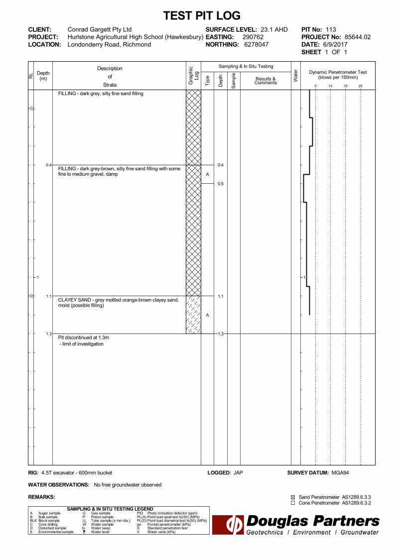
0.4
1.1
1.3
FILLING - dark grey, silty fine sand filling
FILLING - dark grey-brown, silty fine sand filling with somefine to medium gravel, damp
CLAYEY SAND - grey mottled orange-brown clayey sand,moist (possible filling)
Pit discontinued at 1.3m - limit of investigation
SAMPLING & IN SITU TESTING LEGEND
1
RL
2322
TEST PIT LOG
Depth(m)
Londonderry Road, Richmond
A Auger sample G Gas sample PID Photo ionisation detector (ppm)B Bulk sample P Piston sample PL(A) Point load axial test Is(50) (MPa)BLK Block sample Ux Tube sample (x mm dia.) PL(D) Point load diametral test Is(50) (MPa)C Core drilling W Water sample pp Pocket penetrometer (kPa)D Disturbed sample Water seep S Standard penetration testE Environmental sample Water level V Shear vane (kPa)
Conrad Gargett Pty LtdHurlstone Agricultural High School (Hawkesbury)
Results &Comments
LOGGED: JAP SURVEY DATUM: MGA94
CLIENT:PROJECT:LOCATION:
PIT No: 113PROJECT No: 85644.02DATE: 6/9/2017SHEET 1 OF 1
Sampling & In Situ Testing
1
Wat
er
Dep
th
Sam
ple
Description
of
Strata Gra
phic
Log
Typ
e
REMARKS:
RIG: 4.5T excavator - 600mm bucket
WATER OBSERVATIONS: No free groundwater observed
SURFACE LEVEL: 23.1 AHDEASTING: 290762NORTHING: 6278047
Dynamic Penetrometer Test(blows per 150mm)
5 10 15 20
Cone Penetrometer AS1289.6.3.2Sand Penetrometer AS1289.6.3.3
A
A
0.4
0.5
1.1
1.3

Appendix D
Previous Field Work Results

TOPSOIL - dark grey-brown silty fine grained sand topsoilwith rootlets, dry to humid
SILTY SAND - medium dense, dark grey-brown silty finegrained sand, humid
- with some clay, grey-brown fine to medium grained,moist below 0.9m depth - becoming slightly clayey below 1.2m depth
CLAYEY SAND - medium dense, grey clayey fine tomedium grained sand, moist to wet
SILTY CLAY - very stiff, grey and orange-brown mottled,silty, high plasticily clay with a trace of fine grained sand,moist
- becoming grey and slightly sandy below 5.7m depth.Sand fraction fine grained
SANDY SILTY CLAY - very stiff, grey sandy silty mediumplastic clay. Sand fraction fine grained
Bore discontinued at 7.45m - limit of investigation
0.3
3.4
4.0
7.0
7.45
Typ
e
2322
2120
1918
1716
1514
Depth(m)
1
2
3
4
5
6
7
8
9
RL
Wat
er
Dep
th
Sam
ple
Description
of
Strata Gra
phic
Log
Results &Comments
Sampling & In Situ Testing
1
2
3
4
5
6
7
8
9
CLIENT:PROJECT:LOCATION: Londonderry Road, Richmond
SAMPLING & IN SITU TESTING LEGENDA Auger sample G Gas sample PID Photo ionisation detector (ppm)B Bulk sample P Piston sample PL(A) Point load axial test Is(50) (MPa)BLK Block sample Ux Tube sample (x mm dia.) PL(D) Point load diametral test Is(50) (MPa)C Core drilling W Water sample pp Pocket penetrometer (kPa)D Disturbed sample Water seep S Standard penetration testE Environmental sample Water level V Shear vane (kPa)
BORE No: 1PROJECT No: 85644.00DATE: 21/10/2016SHEET 1 OF 1
DRILLER: GM LOGGED: DCH CASING: Uncased
Conrad Gargett Pty LtdHurlstone Agricultural High School (Hawkesbury)
REMARKS:
RIG: DT250
WATER OBSERVATIONS:
TYPE OF BORING:
Free groundwater observed at 2.5m
Solid flight auger to 7.0m
SURFACE LEVEL: 23.4 AHDEASTING: 290646NORTHING: 6278336DIP/AZIMUTH: 90°/--
BOREHOLE LOG
Well
Construction
Details0.0-1.5m: Bulk sample
2,4,7N = 11
Rec = 350mm
8,1216refusal
Rec = 0.4m
4,8,10N = 18
Rec = 350mmpp = 400
6,11,13N = 24
Rec = 450mmpp = 200-250
8,12,16N = 28
Rec = 350mmpp = 350
A
A
A
S
A
S
D
S
S
S
0.00.1
0.5
1.0
1.351.5
2.5
2.9
3.5
4.0
4.35
5.5
5.95
7.0
7.357.45

TOPSOIL - dark grey-brown silty fine grained sand topsoilwith rootlets, dry to humid
SILTY SAND - medium dense, grey-brown silty finegrained sand, humid
- with some clay, grey-brown and orange-brown mottled,with fine to medium grained sand, moist below 0.9m depth - becoming dense below 1.0m depth - becoming fine grained, slightly clayey below 1.1m depth
- with some clay, becoming orange-brown below 2.6mdepth
SILTY CLAY -stiff, grey with orange-brown mottled, siltyhigh plasticity clay with a trace of fine grained sand, moist
- becoming very stiff and grey below 5.5m depth
- becoming grey and orange-brown and black mottledbelow 7.3m depth
Bore discontinued at 7.45m - limit of investigation
0.2
4.0
7.45
Typ
e
2322
2120
1918
1716
1514
Depth(m)
1
2
3
4
5
6
7
8
9
RL
Wat
er
Dep
th
Sam
ple
Description
of
Strata Gra
phic
Log
Results &Comments
Sampling & In Situ Testing
1
2
3
4
5
6
7
8
9
CLIENT:PROJECT:LOCATION: Londonderry Road, Richmond
SAMPLING & IN SITU TESTING LEGENDA Auger sample G Gas sample PID Photo ionisation detector (ppm)B Bulk sample P Piston sample PL(A) Point load axial test Is(50) (MPa)BLK Block sample Ux Tube sample (x mm dia.) PL(D) Point load diametral test Is(50) (MPa)C Core drilling W Water sample pp Pocket penetrometer (kPa)D Disturbed sample Water seep S Standard penetration testE Environmental sample Water level V Shear vane (kPa)
BORE No: 2PROJECT No: 85644.00DATE: 21/10/2016SHEET 1 OF 1
DRILLER: GM LOGGED: DCH CASING: Uncased
Conrad Gargett Pty LtdHurlstone Agricultural High School (Hawkesbury)
REMARKS:
RIG: DT250
WATER OBSERVATIONS:
TYPE OF BORING:
No free groundwater observed
Solid flight auger to 7.0m
SURFACE LEVEL: 23.2 AHDEASTING: 290641NORTHING: 6278178DIP/AZIMUTH: 90°/--
BOREHOLE LOG
Well
Construction
Details
3,13,24N = 37
Rec = 450mm
10,18,21N = 39
Rec = 330
3,5,7N = 12
Rec = 360pp = 150-200
5,10,11N = 21
Rec = 340mmpp = 300
6,9,11N = 20
Rec = 450mmpp = 200-250
A
A
A
S
A
S
S
S
S
0.00.1
0.5
1.0
1.451.5
2.5
2.83
4.0
4.36
5.5
5.84
7.0
7.45

TOPSOIL - dark grey-brown silty fine grained sand topsoilwith a trace of fine grained gravel, dry to moist
SILTY SAND - dense to very dense, light grey-brown siltyfine grained sand, slightly clayey, damp to moist
SILTY CLAY - very stiff, light grey and orange-brownmottled, silty clay with a trace of fine grained sand, clayfraction is low to medium plasticity, M<Wp
5.5m: becoming light grey below 5.5m
7.0m: becoming hard, light grey, orange-brown and yellowbrown mottled below 7.0m
Bore discontinued at 7.45m - limit of investigation
0.5
4.0
7.45
Typ
e
2322
2120
1918
1716
1514
Depth(m)
1
2
3
4
5
6
7
8
9
RL
Wat
er
Dep
th
Sam
ple
Description
of
Strata Gra
phic
Log
Results &Comments
Sampling & In Situ Testing
1
2
3
4
5
6
7
8
9
CLIENT:PROJECT:LOCATION: Londonderry Road, Richmond
SAMPLING & IN SITU TESTING LEGENDA Auger sample G Gas sample PID Photo ionisation detector (ppm)B Bulk sample P Piston sample PL(A) Point load axial test Is(50) (MPa)BLK Block sample Ux Tube sample (x mm dia.) PL(D) Point load diametral test Is(50) (MPa)C Core drilling W Water sample pp Pocket penetrometer (kPa)D Disturbed sample Water seep S Standard penetration testE Environmental sample Water level V Shear vane (kPa)
BORE No: 3PROJECT No: 85644.00DATE: 27/9/2016SHEET 1 OF 1
DRILLER: JS LOGGED: DCH CASING: Uncased
Conrad Gargett Pty LtdHurlstone Agricultural High School (Hawkesbury)
REMARKS:
RIG: Explora 140
WATER OBSERVATIONS:
TYPE OF BORING:
No free groundwater observed
Solid flight auger to 7.0m
SURFACE LEVEL: 23.0 AHDEASTING: 290634NORTHING: 6278036DIP/AZIMUTH: 90°/--
BOREHOLE LOG
Well
Construction
Details
13,25,28N = 53
16,22,20N = 42
7,9,11N = 20
6,10,13N = 23
10,15,22N = 37
A/E
A/E
A/E
S
S
S
S
S
0.1
0.5
1.0
1.45
2.5
2.95
4.0
4.45
5.5
5.95
7.0
7.45

TOPSOIL - dark grey-brown, silty fine grained sandtopsoil with a trace of fine grained rounded gravel, dry tomoist
SILTY SAND - dense, light grey, silty fine grained sand,slightly clayey, dry to moist
CLAYEY SAND - medium dense, light grey and brownmottled, clayey, fine grained sand
SILTY CLAY - very stiff, light grey and brown mottled, siltyclay with a trace of fine grained sand. Clay fraction is lowplasticity - becoming light grey below 4.1m
SANDY SILT - hard, light grey-brown sandy silt, slightlyclayey. Sand fraction is fine grained
Bore discontinued at 7.45m - limit of investigation
0.3
2.5
4.0
7.0
7.45
Typ
e
2322
2120
1918
1716
1514
Depth(m)
1
2
3
4
5
6
7
8
9
RL
Wat
er
Dep
th
Sam
ple
Description
of
Strata Gra
phic
Log
Results &Comments
Sampling & In Situ Testing
1
2
3
4
5
6
7
8
9
CLIENT:PROJECT:LOCATION: Londonderry Road, Richmond
SAMPLING & IN SITU TESTING LEGENDA Auger sample G Gas sample PID Photo ionisation detector (ppm)B Bulk sample P Piston sample PL(A) Point load axial test Is(50) (MPa)BLK Block sample Ux Tube sample (x mm dia.) PL(D) Point load diametral test Is(50) (MPa)C Core drilling W Water sample pp Pocket penetrometer (kPa)D Disturbed sample Water seep S Standard penetration testE Environmental sample Water level V Shear vane (kPa)
BORE No: 4PROJECT No: 85644.00DATE: 27/9/2016SHEET 1 OF 1
DRILLER: JS LOGGED: DCH CASING: Uncased
Conrad Gargett Pty LtdHurlstone Agricultural High School (Hawkesbury)
REMARKS:
RIG: Explora 140
WATER OBSERVATIONS:
TYPE OF BORING:
Free groundwater observed at 1.9m
Solid flight auger to 7.0m
SURFACE LEVEL: 23.3 AHDEASTING: 290772NORTHING: 6278209DIP/AZIMUTH: 90°/--
BOREHOLE LOG
Well
Construction
Details
20,30/140mmrefusal
9,11,18N = 29
7,9,11N = 20
5,9,11N = 20
12,15,18N = 33
A
A
AS
S
S
S
S
0.2
0.5
1.01.14
2.5
2.95
4.0
4.45
5.5
5.95
7.0
7.45

TOPSOIL - dark grey-brown, silty fine grained sandtopsoil, dry to moist
SILTY SAND - medium dense, grey-brown silty finegrained sand, moist
- becoming wet below 0.9m
CLAYEY SAND - medium dense, light grey andorange-brown mottled, clayey fine grained sand
- becoming orange-brown below 2.5m
SILTY CLAY - very stiff, grey and orange-brown mottledsilty clay. Clay fraction is low to medium plasticity, M<Wpto M~Wp
Bore discontinued at 7.45m - limit of investigation
0.2
1.0
4.8
7.45
Typ
e
2322
2120
1918
1716
1514
Depth(m)
1
2
3
4
5
6
7
8
9
RL
Wat
er
Dep
th
Sam
ple
Description
of
Strata Gra
phic
Log
Results &Comments
Sampling & In Situ Testing
1
2
3
4
5
6
7
8
9
CLIENT:PROJECT:LOCATION: Londonderry Road, Richmond
SAMPLING & IN SITU TESTING LEGENDA Auger sample G Gas sample PID Photo ionisation detector (ppm)B Bulk sample P Piston sample PL(A) Point load axial test Is(50) (MPa)BLK Block sample Ux Tube sample (x mm dia.) PL(D) Point load diametral test Is(50) (MPa)C Core drilling W Water sample pp Pocket penetrometer (kPa)D Disturbed sample Water seep S Standard penetration testE Environmental sample Water level V Shear vane (kPa)
BORE No: 5PROJECT No: 85644.00DATE: 28/9/2016SHEET 1 OF 1
DRILLER: RKE LOGGED: DCH CASING: Uncased
Conrad Gargett Pty LtdHurlstone Agricultural High School (Hawkesbury)
REMARKS:
RIG: Scout 4
WATER OBSERVATIONS:
TYPE OF BORING:
Free groundwater observed at 0.9m
Solid flight auger to 7.0m
SURFACE LEVEL: 23.2 AHDEASTING: 290712NORTHING: 6278122DIP/AZIMUTH: 90°/--
BOREHOLE LOG
Well
Construction
Details
0.2-1.0m: Bulk sample
3,4,19N = 23
9,15,13N = 28
5,6,5N = 11
6,10,13N = 23
pp = 400
5,8,12N = 20
pp = 400
A/E
A
A
S
S
S
S
S
0.10.2
0.5
1.0
1.35
2.5
2.95
4.0
4.4
5.5
5.95
7.0
7.45

TOPSOIL - dark grey-brown silty fine grained sand topsoilwith some fine to medium subangular to angular gravel,dry
FILLING - very loose, dark grey-brown silty fine grainedsand filling, slightly gravelly. Gravel fraction fine tomedium subangular to angular - with rubbish inclusions, plastic bags, rags and plasticbottles below 0.5m - becoming slightly clayey below 1.0m
CLAYEY SAND - medium dense to dense, lightyellow-grey and orange-brown mottled, clayey fine grainedsand
SILTY CLAY - stiff, light grey and yellow-brown mottled,silty clay with some sand. Sand fraction is fine grained,clay is low plasticity
SILTY CLAY - very stiff, grey-brown and brown, silty claywith a trace of fine grained sand
- becoming hard below 7.0m
Bore discontinued at 7.45m - limit of investigation
0.2
2.5
4.0
5.25
7.45
Typ
e
2322
2120
1918
1716
1514
Depth(m)
1
2
3
4
5
6
7
8
9
RL
Wat
er
Dep
th
Sam
ple
Description
of
Strata Gra
phic
Log
Results &Comments
Sampling & In Situ Testing
1
2
3
4
5
6
7
8
9
CLIENT:PROJECT:LOCATION: Londonderry Road, Richmond
SAMPLING & IN SITU TESTING LEGENDA Auger sample G Gas sample PID Photo ionisation detector (ppm)B Bulk sample P Piston sample PL(A) Point load axial test Is(50) (MPa)BLK Block sample Ux Tube sample (x mm dia.) PL(D) Point load diametral test Is(50) (MPa)C Core drilling W Water sample pp Pocket penetrometer (kPa)D Disturbed sample Water seep S Standard penetration testE Environmental sample Water level V Shear vane (kPa)
BORE No: 6PROJECT No: 85644.00DATE: 27/9/2016SHEET 1 OF 1
DRILLER: JS LOGGED: DCH CASING: Uncased
Conrad Gargett Pty LtdHurlstone Agricultural High School (Hawkesbury)
REMARKS:
RIG: Explora 140
WATER OBSERVATIONS:
TYPE OF BORING:
Free groundwater observed at 1.0m
Solid flight auger to 7.0m
SURFACE LEVEL: 23.3 AHDEASTING: 290772NORTHING: 6278063DIP/AZIMUTH: 90°/--
BOREHOLE LOG
Well
Construction
Details
0,1,2N = 3
13,14,16N = 30
3,3,8N = 11
8,10,15N = 25
10,14,17N = 31
A
A
A
S
S
S
S
S
0.1
0.5
1.0
1.45
2.5
2.95
4.0
4.45
5.5
5.95
7.0
7.45

TOPSOIL - dark grey-brown silty fine grained sand topsoil
SILTY SAND - dense, grey silty fine grained sand, wet - becoming yellow-brown below 0.4m
- becoming slightly clayey below 1.2m
CLAYEY SAND - dense, light grey clayey fine grainedsand, moist
SILTY CLAY - very stiff, grey and yellow-brown mottled,silty clay with a trace of fine grained sand. Clay fraction islow plasticity, M<Wp
- becoming hard below 7.0m depth
Bore discontinued at 7.45m - limit of investigation
0.1
2.5
3.9
7.45
Typ
e
2322
2120
1918
1716
1514
Depth(m)
1
2
3
4
5
6
7
8
9
RL
Wat
er
Dep
th
Sam
ple
Description
of
Strata Gra
phic
Log
Results &Comments
Sampling & In Situ Testing
1
2
3
4
5
6
7
8
9
CLIENT:PROJECT:LOCATION: Londonderry Road, Richmond
SAMPLING & IN SITU TESTING LEGENDA Auger sample G Gas sample PID Photo ionisation detector (ppm)B Bulk sample P Piston sample PL(A) Point load axial test Is(50) (MPa)BLK Block sample Ux Tube sample (x mm dia.) PL(D) Point load diametral test Is(50) (MPa)C Core drilling W Water sample pp Pocket penetrometer (kPa)D Disturbed sample Water seep S Standard penetration testE Environmental sample Water level V Shear vane (kPa)
BORE No: 7PROJECT No: 85644.00DATE: 27/9/2016SHEET 1 OF 1
DRILLER: JS LOGGED: DCH CASING: Uncased
Conrad Gargett Pty LtdHurlstone Agricultural High School (Hawkesbury)
REMARKS:
RIG: Explora 140
WATER OBSERVATIONS:
TYPE OF BORING:
Free groundwater observed at 0.3m
Solid flight auger to 7.0m
SURFACE LEVEL: 23.0 AHDEASTING: 291004NORTHING: 6278212DIP/AZIMUTH: 90°/--
BOREHOLE LOG
Well
Construction
Details
11,24,15/100mmrefusal
10,13,17N = 30
4,9,15N = 24
6,11,13N = 24
15,22,22N = 44
A/E
S
S
S
S
S
0.1
1.0
1.45
2.5
2.95
4.0
4.85
5.5
5.95
7.0
7.45

TOPSOIL - dark grey-brown silty fine grained sandtopsoil, dry to moist
SILTY SAND - dense, dark grey-brown, silty fine grainedsand, dry to moist
- becoming light grey-brown below 0.9m
- becoming slightly clayey below 1.1m
- becoming medium dense below 2.5m
SILTY CLAY - stiff, light grey and orange-brown mottled,silty clay with a trace of fine grained sand, M<Wp
- becoming very stiff below 5.5m
Bore discontinued at 7.45m - limit of investigation
0.3
4.0
7.45
Typ
e
2221
2019
1817
1615
1413
Depth(m)
1
2
3
4
5
6
7
8
9
RL
Wat
er
Dep
th
Sam
ple
Description
of
Strata Gra
phic
Log
Results &Comments
Sampling & In Situ Testing
1
2
3
4
5
6
7
8
9
CLIENT:PROJECT:LOCATION: Londonderry Road, Richmond
SAMPLING & IN SITU TESTING LEGENDA Auger sample G Gas sample PID Photo ionisation detector (ppm)B Bulk sample P Piston sample PL(A) Point load axial test Is(50) (MPa)BLK Block sample Ux Tube sample (x mm dia.) PL(D) Point load diametral test Is(50) (MPa)C Core drilling W Water sample pp Pocket penetrometer (kPa)D Disturbed sample Water seep S Standard penetration testE Environmental sample Water level V Shear vane (kPa)
BORE No: 8PROJECT No: 85644.00DATE: 27/9/2016SHEET 1 OF 1
DRILLER: RKE LOGGED: DCH CASING: Uncased
Conrad Gargett Pty LtdHurlstone Agricultural High School (Hawkesbury)
REMARKS:
RIG: Scout 4
WATER OBSERVATIONS:
TYPE OF BORING:
Free groundwater observed at 0.7m
Solid flight auger to 7.0m
SURFACE LEVEL: 22.9 AHDEASTING: 290940NORTHING: 6278122DIP/AZIMUTH: 90°/--
BOREHOLE LOG
Well
Construction
Details0.0-1.0m: Bulk sample
6,13,21N = 34
7,11,15N = 26
4,6,8N = 14
5,8,13N = 21
7,10,11N = 21
A
A
A
S
S
S
S
S
0.00.1
0.5
1.0
1.45
2.5
2.95
4.0
4.45
5.5
5.95
7.0
7.45

TOPSOIL - dark grey-brown, silty fine grained sandtopsoil, dry to moist
CLAYEY SILTY SAND - medium dense, light grey andbrown mottled clayey silty fine grained sand, wet
SILTY SAND - dense, light grey and brown mottled, siltyfine grained sand, slightly clayey
SANDY SILT - stiff, light grey and brown mottled, sandysilt, slightly clayey, sand fraction is fine grained
SILTY CLAY - very stiff, light grey and brown mottled, siltyclay with a trace of fine grained sand, M<Wp
- becoming hard below 7.0m
Bore discontinued at 7.45m - limit of investigation
0.9
2.5
4.0
5.0
7.45
Typ
e
2322
2120
1918
1716
1514
Depth(m)
1
2
3
4
5
6
7
8
9
RL
Wat
er
Dep
th
Sam
ple
Description
of
Strata Gra
phic
Log
Results &Comments
Sampling & In Situ Testing
1
2
3
4
5
6
7
8
9
CLIENT:PROJECT:LOCATION: Londonderry Road, Richmond
SAMPLING & IN SITU TESTING LEGENDA Auger sample G Gas sample PID Photo ionisation detector (ppm)B Bulk sample P Piston sample PL(A) Point load axial test Is(50) (MPa)BLK Block sample Ux Tube sample (x mm dia.) PL(D) Point load diametral test Is(50) (MPa)C Core drilling W Water sample pp Pocket penetrometer (kPa)D Disturbed sample Water seep S Standard penetration testE Environmental sample Water level V Shear vane (kPa)
BORE No: 9PROJECT No: 85644.00DATE: 27/9/2016SHEET 1 OF 1
DRILLER: RKE LOGGED: DCH CASING: Uncased
Conrad Gargett Pty LtdHurlstone Agricultural High School (Hawkesbury)
REMARKS:
RIG: Scout 4
WATER OBSERVATIONS:
TYPE OF BORING:
Free groundwater observed at 0.9m
Solid flight auger to 7.0m
SURFACE LEVEL: 23.0 AHDEASTING: 290856NORTHING: 6278041DIP/AZIMUTH: 90°/--
BOREHOLE LOG
Well
Construction
Details
7,9,13N = 22
14,19,19N = 38
4,5,5N = 10
5,9,11N = 20
7,13,19N = 32
A
A
S
S
S
S
S
0.1
0.5
1.0
1.45
2.5
2.95
4.0
4.45
5.5
5.95
7.0
7.45

TOPSOIL - dark grey-brown silty sand topsoil, dry
SILTY SAND - medium dense, light grey-brown silty sandwith a trace of clay, moist
CLAYEY SILTY SAND - medium dense, light grey andbrown mottled, clayey silty fine grained sand
SILTY CLAY - very stiff, grey and brown mottled silty claywith a trace of fine grained sand, clay fraction is lowplasticity
Bore discontinued at 7.45m - limit of investigation
0.5
1.2
4.3
7.45
Typ
e
2221
2019
1817
1615
1413
Depth(m)
1
2
3
4
5
6
7
8
9
RL
Wat
er
Dep
th
Sam
ple
Description
of
Strata Gra
phic
Log
Results &Comments
Sampling & In Situ Testing
1
2
3
4
5
6
7
8
9
CLIENT:PROJECT:LOCATION: Londonderry Road, Richmond
SAMPLING & IN SITU TESTING LEGENDA Auger sample G Gas sample PID Photo ionisation detector (ppm)B Bulk sample P Piston sample PL(A) Point load axial test Is(50) (MPa)BLK Block sample Ux Tube sample (x mm dia.) PL(D) Point load diametral test Is(50) (MPa)C Core drilling W Water sample pp Pocket penetrometer (kPa)D Disturbed sample Water seep S Standard penetration testE Environmental sample Water level V Shear vane (kPa)
BORE No: 10PROJECT No: 85644.00DATE: 27/9/2016SHEET 1 OF 1
DRILLER: RKE LOGGED: DCH CASING: Uncased
Conrad Gargett Pty LtdHurlstone Agricultural High School (Hawkesbury)
REMARKS:
RIG: Scout 4
WATER OBSERVATIONS:
TYPE OF BORING:
Free groundwater observed at 0.9m
Solid flight auger to 7.0m
SURFACE LEVEL: 22.8 AHDEASTING: 291041NORTHING: 6277983DIP/AZIMUTH: 90°/--
BOREHOLE LOG
Well
Construction
Details
4,9,9N = 18
5,10,9N = 19
5,9,12N = 21
3,7,10N = 17
6,11,18N = 29
S
S
S
S
S
1.0
1.45
2.5
2.95
4.0
4.45
5.5
5.95
7.0
7.45

TOPSOIL - dark grey-brown, silty fine grained sandtopsoil with rootlets, dry
SILTY SAND - medium dense, dark grey-brown, silty finegrained sand, dry - becoming light grey-brown and moist below 0.6m
CLAYEY SAND - medium dense, light grey andorange-brown mottled, clayey fine grained sand with somesilt, moist
SILTY CLAY - very stiff, light grey and orange-brownmottled, silty clay with a trace of fine grained sand. Clayfraction is low plasticity, M<Wp
5.5m: becoming light grey below 5.5m
Bore discontinued at 7.45m - limit of investigation
0.2
1.2
4.2
7.45
Typ
e
2221
2019
1817
1615
1413
Depth(m)
1
2
3
4
5
6
7
8
9
RL
Wat
er
Dep
th
Sam
ple
Description
of
Strata Gra
phic
Log
Results &Comments
Sampling & In Situ Testing
1
2
3
4
5
6
7
8
9
CLIENT:PROJECT:LOCATION: Londonderry Road, Richmond
SAMPLING & IN SITU TESTING LEGENDA Auger sample G Gas sample PID Photo ionisation detector (ppm)B Bulk sample P Piston sample PL(A) Point load axial test Is(50) (MPa)BLK Block sample Ux Tube sample (x mm dia.) PL(D) Point load diametral test Is(50) (MPa)C Core drilling W Water sample pp Pocket penetrometer (kPa)D Disturbed sample Water seep S Standard penetration testE Environmental sample Water level V Shear vane (kPa)
BORE No: 11PROJECT No: 85644.00DATE: 27/9/2016SHEET 1 OF 1
DRILLER: RKE LOGGED: DCH CASING: Uncased
Conrad Gargett Pty LtdHurlstone Agricultural High School (Hawkesbury)
REMARKS:
RIG: Scout 4
WATER OBSERVATIONS:
TYPE OF BORING:
Free groundwater observed at 0.9m
Solid flight auger to 7.0m
SURFACE LEVEL: 22.9 AHDEASTING: 290991NORTHING: 6277929DIP/AZIMUTH: 90°/--
BOREHOLE LOG
Well
Construction
Details0.0-1.0m: Bulk sample
3,3,19N = 22
3,7,9N = 16
6,9,12N = 21
5,8,9N = 17
5,7,12N = 19
A/E
A/E
A/E
S
S
S
S
S
0.00.1
0.5
1.0
1.45
2.5
2.95
4.0
4.45
5.5
5.95
7.0
7.45

Appendix E
Laboratory Test Results

Material Test Report
Report Number: 85644.00-1
Issue Number: 1
Date Issued: 01/11/2016
Client: Conrad Gargett Pty Ltd
Suite C.3.18/22-36 Mountain Street, ULTIMO NSW 2007
Project Number: 85644.00
Project Name: Hurlstone Hawkesbury STEMAg High School
Project Location: Londonderry Road, Richmond
Work Request: 146
Sample Number: 16-146A
Date Sampled: 05/10/2016
Sampling Method: Sampled by Engineering Department
Sample Location: Bore 5 (0.2 - 1.0m)
Material: Silty SAND
Douglas Partners Pty Ltd
Newcastle Laboratory
15 Callistemon Close Warabrook Newcastle NSW 2310
Phone: (02) 4960 9600
Fax: (02) 4960 9601
Email: [email protected]
Accredited for compliance with ISO/IEC 17025 - Testing
Approved Signatory: Dave Millard
Nata Accredited Laboratory Number: 828
Moisture Content (AS 1289 2.1.1)
Moisture Content (%) 12.2
Moisture Density Relationship (AS 1289 5.1.1 & 2.1.1)
Mould Type 1 LITRE MOULD A
Compaction Standard
No. Layers 3
No. Blows / Layer 25
Maximum Dry Density (t/m3) 1.91
Optimum Moisture Content (%) 9.5
Oversize Material (%) 0
California Bearing Ratio (AS 1289 6.1.1 & 2.1.1) Min Max
CBR taken at 5 mm
CBR % 25
Method of Compactive Effort Standard
Method used to Determine MDD AS 1289 5.1.1 & 2.1.1
Maximum Dry Density (t/m3) 1.91
Dry Density after Soaking (t/m3) 1.94
Optimum Moisture Content (%) 9.5
Laboratory Moisture Ratio (%) 103.0
Laboratory Density Ratio (%) 99.5
Moisture Content at Placement (%) 9.9
Moisture Content Top 30mm (%) 10.7
Moisture Content Rest of Sample (%) 11.7
Mass Surcharge (kg) 4.5
Soaking Period (days) 4
Swell (%) -0.5
Oversize Material (mm) 19
Oversize Material Included Excluded
Oversize Material (%) 0
Moisture Density Relationship
Points
MDD OMC
Zero Air Void
4 5 6 7 8 9 1 0 1 1 1 2 1 3 1 4 1 5 1 6
1.83
1.84
1.85
1.86
1.87
1.88
1.89
1.9
1.91
1.92
1.93
California Bearing Ratio
Results 2.5 5 Tangent Corrected
0 1 2 3 4 5 6 7 8 9 1 0 1 1 1 2 1 3
0
1
2
3
4
5
6
7
8
9
1 0
1 1
Report Number: 85644.00-1 Page 1 of 6

Material Test Report
Report Number: 85644.00-1
Issue Number: 1
Date Issued: 01/11/2016
Client: Conrad Gargett Pty Ltd
Suite C.3.18/22-36 Mountain Street, ULTIMO NSW 2007
Project Number: 85644.00
Project Name: Hurlstone Hawkesbury STEMAg High School
Project Location: Londonderry Road, Richmond
Work Request: 146
Sample Number: 16-146B
Date Sampled: 05/10/2016
Sampling Method: Sampled by Engineering Department
Sample Location: Bore 8 (0.0 - 1.0m)
Material: Silty SAND
Douglas Partners Pty Ltd
Newcastle Laboratory
15 Callistemon Close Warabrook Newcastle NSW 2310
Phone: (02) 4960 9600
Fax: (02) 4960 9601
Email: [email protected]
Accredited for compliance with ISO/IEC 17025 - Testing
Approved Signatory: Dave Millard
Nata Accredited Laboratory Number: 828
Moisture Content (AS 1289 2.1.1)
Moisture Content (%) 10.2
Moisture Density Relationship (AS 1289 5.1.1 & 2.1.1)
Mould Type 1 LITRE MOULD A
Compaction Standard
No. Layers 3
No. Blows / Layer 25
Maximum Dry Density (t/m3) 1.93
Optimum Moisture Content (%) 9.5
Oversize Material (%) 0
California Bearing Ratio (AS 1289 6.1.1 & 2.1.1) Min Max
CBR taken at 5 mm
CBR % 11
Method of Compactive Effort Standard
Method used to Determine MDD AS 1289 5.1.1 & 2.1.1
Maximum Dry Density (t/m3) 1.93
Dry Density after Soaking (t/m3) 1.94
Optimum Moisture Content (%) 9.5
Laboratory Moisture Ratio (%) 103.0
Laboratory Density Ratio (%) 99.5
Moisture Content at Placement (%) 9.7
Moisture Content Top 30mm (%) 11.2
Moisture Content Rest of Sample (%) 11.1
Mass Surcharge (kg) 4.5
Soaking Period (days) 4
Swell (%) -0.5
Oversize Material (mm) 19
Oversize Material Included Excluded
Oversize Material (%) 0
Moisture Density Relationship
Points
MDD OMC
Zero Air Void
5 6 7 8 9 1 0 1 1 1 2 1 3 1 4 1 5
1.86
1.87
1.88
1.89
1.9
1.91
1.92
1.93
1.94
1.95
California Bearing Ratio
Results 2.5 5 Tangent Corrected
0 1 2 3 4 5 6 7 8 9 1 0 1 1 1 2 1 3
0
1
2
3
4
5
6
Report Number: 85644.00-1 Page 2 of 6

Material Test Report
Report Number: 85644.00-1
Issue Number: 1
Date Issued: 01/11/2016
Client: Conrad Gargett Pty Ltd
Suite C.3.18/22-36 Mountain Street, ULTIMO NSW 2007
Project Number: 85644.00
Project Name: Hurlstone Hawkesbury STEMAg High School
Project Location: Londonderry Road, Richmond
Work Request: 146
Sample Number: 16-146C
Date Sampled: 05/10/2016
Sampling Method: Sampled by Engineering Department
Sample Location: Bore 11 (0.0 - 1.0m)
Material: Silty SAND
Douglas Partners Pty Ltd
Newcastle Laboratory
15 Callistemon Close Warabrook Newcastle NSW 2310
Phone: (02) 4960 9600
Fax: (02) 4960 9601
Email: [email protected]
Accredited for compliance with ISO/IEC 17025 - Testing
Approved Signatory: Dave Millard
Nata Accredited Laboratory Number: 828
Moisture Content (AS 1289 2.1.1)
Moisture Content (%) 10.5
Moisture Density Relationship (AS 1289 5.1.1 & 2.1.1)
Mould Type 1 LITRE MOULD A
Compaction Standard
No. Layers 3
No. Blows / Layer 25
Maximum Dry Density (t/m3) 1.89
Optimum Moisture Content (%) 11.0
Oversize Material (%) 0
California Bearing Ratio (AS 1289 6.1.1 & 2.1.1) Min Max
CBR taken at 5 mm
CBR % 20
Method of Compactive Effort Standard
Method used to Determine MDD AS 1289 5.1.1 & 2.1.1
Maximum Dry Density (t/m3) 1.89
Dry Density after Soaking (t/m3) 1.88
Optimum Moisture Content (%) 11.0
Laboratory Moisture Ratio (%) 104.5
Laboratory Density Ratio (%) 99.0
Moisture Content at Placement (%) 11.3
Moisture Content Top 30mm (%) 12.4
Moisture Content Rest of Sample (%) 11.5
Mass Surcharge (kg) 4.5
Soaking Period (days) 4
Swell (%) -0.5
Oversize Material (mm) 19
Oversize Material Included Excluded
Oversize Material (%) 0
Moisture Density Relationship
Points
MDD OMC
Zero Air Void
7 8 9 1 0 1 1 1 2 1 3 1 4
1.78
1.79
1.8
1.81
1.82
1.83
1.84
1.85
1.86
1.87
1.88
1.89
1.9
1.91
California Bearing Ratio
Results 2.5 5 Tangent Corrected
0 1 2 3 4 5 6 7 8 9 1 0 1 1 1 2 1 3
0
1
2
3
4
5
6
7
8
9
Report Number: 85644.00-1 Page 3 of 6

Material Test Report
Report Number: 85644.00-1
Issue Number: 1
Date Issued: 01/11/2016
Client: Conrad Gargett Pty Ltd
Suite C.3.18/22-36 Mountain Street, ULTIMO NSW 2007
Project Number: 85644.00
Project Name: Hurlstone Hawkesbury STEMAg High School
Project Location: Londonderry Road, Richmond
Work Request: 146
Sample Number: 16-146D
Date Sampled: 05/10/2016
Sampling Method: Sampled by Engineering Department
Sample Location: Bore 3 (4.00 - 4.95m)
Material: Silty CLAY
Douglas Partners Pty Ltd
Newcastle Laboratory
15 Callistemon Close Warabrook Newcastle NSW 2310
Phone: (02) 4960 9600
Fax: (02) 4960 9601
Email: [email protected]
Accredited for compliance with ISO/IEC 17025 - Testing
Approved Signatory: Dave Millard
Nata Accredited Laboratory Number: 828
Moisture Content (AS 1289 2.1.1)
Moisture Content (%) 16.0
Atterberg Limit (AS1289 3.1.2 & 3.2.1 & 3.3.1) Min Max
Preparation Method Dry Sieve
Sample History Oven Dried
Liquid Limit (%) 29
Plastic Limit (%) 12
Plasticity Index (%) 17
Linear Shrinkage (AS1289 3.4.1) Min Max
Linear Shrinkage (%) 11.0
Cracking Crumbling Curling Curling
Report Number: 85644.00-1 Page 4 of 6

Material Test Report
Report Number: 85644.00-1
Issue Number: 1
Date Issued: 01/11/2016
Client: Conrad Gargett Pty Ltd
Suite C.3.18/22-36 Mountain Street, ULTIMO NSW 2007
Project Number: 85644.00
Project Name: Hurlstone Hawkesbury STEMAg High School
Project Location: Londonderry Road, Richmond
Work Request: 146
Sample Number: 16-146E
Date Sampled: 05/10/2016
Sampling Method: Sampled by Engineering Department
Sample Location: Bore 7 (4.00 - 4.95m)
Material: Silty CLAY
Douglas Partners Pty Ltd
Newcastle Laboratory
15 Callistemon Close Warabrook Newcastle NSW 2310
Phone: (02) 4960 9600
Fax: (02) 4960 9601
Email: [email protected]
Accredited for compliance with ISO/IEC 17025 - Testing
Approved Signatory: Dave Millard
Nata Accredited Laboratory Number: 828
Moisture Content (AS 1289 2.1.1)
Moisture Content (%) 18.7
Atterberg Limit (AS1289 3.1.2 & 3.2.1 & 3.3.1) Min Max
Preparation Method Dry Sieve
Sample History Oven Dried
Liquid Limit (%) 41
Plastic Limit (%) 14
Plasticity Index (%) 27
Linear Shrinkage (AS1289 3.4.1) Min Max
Linear Shrinkage (%) 14.0
Cracking Crumbling Curling Curling
Report Number: 85644.00-1 Page 5 of 6

Material Test Report
Report Number: 85644.00-1
Issue Number: 1
Date Issued: 01/11/2016
Client: Conrad Gargett Pty Ltd
Suite C.3.18/22-36 Mountain Street, ULTIMO NSW 2007
Project Number: 85644.00
Project Name: Hurlstone Hawkesbury STEMAg High School
Project Location: Londonderry Road, Richmond
Work Request: 146
Sample Number: 16-146F
Date Sampled: 05/10/2016
Sampling Method: Sampled by Engineering Department
Sample Location: Bore 11 (5.50 - 5.95m)
Material: Silty CLAY
Douglas Partners Pty Ltd
Newcastle Laboratory
15 Callistemon Close Warabrook Newcastle NSW 2310
Phone: (02) 4960 9600
Fax: (02) 4960 9601
Email: [email protected]
Accredited for compliance with ISO/IEC 17025 - Testing
Approved Signatory: Dave Millard
Nata Accredited Laboratory Number: 828
Moisture Content (AS 1289 2.1.1)
Moisture Content (%) 17.6
Atterberg Limit (AS1289 3.1.2 & 3.2.1 & 3.3.1) Min Max
Preparation Method Dry Sieve
Sample History Oven Dried
Liquid Limit (%) 42
Plastic Limit (%) 14
Plasticity Index (%) 28
Linear Shrinkage (AS1289 3.4.1) Min Max
Linear Shrinkage (%) 17.5
Cracking Crumbling Curling Curling
Report Number: 85644.00-1 Page 6 of 6

Material Test Report
Report Number: 85644.02-1
Issue Number: 1
Date Issued: 20/09/2017
Client: Conrad Gargett Pty Ltd
Suite C.3.18/22-36 Mountain Street, ULTIMO NSW 2007
Contact: Mark Cassar
Project Number: 85644.02
Project Name: Hurlstone Hawkesbury STEMAg High School
Project Location: Londonderry Road, Richmond
Work Request: 1524
Sample Number: 17-1524A
Date Sampled: 06/09/2017
Sampling Method: Sampled by Engineering Department
Sample Location: TP107 (1.0-1.2m)
Material: Clayey sand
Douglas Partners Pty Ltd
Sydney Laboratory
96 Hermitage Road West Ryde NSW 2114
Phone: (02) 9809 0666
Fax: (02) 9809 0666
Email: [email protected]
Accredited for compliance with ISO/IEC 17025 - Testing
Approved Signatory: Mark Matthews
NATA Accredited Laboratory Number: 828
California Bearing Ratio (AS 1289 6.1.1 & 2.1.1) Min Max
CBR taken at 5 mm
CBR % 7
Method of Compactive Effort Standard
Method used to Determine MDD AS 1289 5.1.1 & 2.1.1
Maximum Dry Density (t/m3) 2.07
Optimum Moisture Content (%) 9.5
Laboratory Density Ratio (%) 100.0
Laboratory Moisture Ratio (%) 99.0
Dry Density after Soaking (t/m3) 2.08
Field Moisture Content (%) 9.9
Moisture Content at Placement (%) 9.3
Moisture Content Top 30mm (%) 10.0
Moisture Content Rest of Sample (%) 9.9
Mass Surcharge (kg) 4.5
Soaking Period (days) 4
Swell (%) -0.5
Oversize Material (mm) 19
Oversize Material Included Excluded
Oversize Material (%) 0
California Bearing Ratio
Results 2.5 5 Tangent Corrected
0 1 2 3 4 5 6 7 8 9 1 0 1 1 1 2 1 3
0
1
2
3
Report Number: 85644.02-1 Page 1 of 2

Material Test Report
Report Number: 85644.02-1
Issue Number: 1
Date Issued: 20/09/2017
Client: Conrad Gargett Pty Ltd
Suite C.3.18/22-36 Mountain Street, ULTIMO NSW 2007
Contact: Mark Cassar
Project Number: 85644.02
Project Name: Hurlstone Hawkesbury STEMAg High School
Project Location: Londonderry Road, Richmond
Work Request: 1524
Sample Number: 17-1524B
Date Sampled: 06/09/2017
Sampling Method: Sampled by Engineering Department
Sample Location: TP108 (1.0-1.1m)
Material: Clayey sand
Douglas Partners Pty Ltd
Sydney Laboratory
96 Hermitage Road West Ryde NSW 2114
Phone: (02) 9809 0666
Fax: (02) 9809 0666
Email: [email protected]
Accredited for compliance with ISO/IEC 17025 - Testing
Approved Signatory: Mark Matthews
NATA Accredited Laboratory Number: 828
California Bearing Ratio (AS 1289 6.1.1 & 2.1.1) Min Max
CBR taken at 5 mm
CBR % 7
Method of Compactive Effort Standard
Method used to Determine MDD AS 1289 5.1.1 & 2.1.1
Maximum Dry Density (t/m3) 1.98
Optimum Moisture Content (%) 11.0
Laboratory Density Ratio (%) 100.0
Laboratory Moisture Ratio (%) 101.0
Dry Density after Soaking (t/m3) 1.98
Field Moisture Content (%) 11.5
Moisture Content at Placement (%) 11.1
Moisture Content Top 30mm (%) 12.3
Moisture Content Rest of Sample (%) 11.7
Mass Surcharge (kg) 4.5
Soaking Period (days) 4
Swell (%) -0.5
Oversize Material (mm) 19
Oversize Material Included Excluded
Oversize Material (%) 0
California Bearing Ratio
Results 2.5 5 Tangent Corrected
0 1 2 3 4 5 6 7 8 9 1 0 1 1 1 2 1 3
0
1
2
3
Report Number: 85644.02-1 Page 2 of 2