report of geotechnical study - newport news regional geology ... automatic hammer is different than...
TRANSCRIPT


Corporate HQ: 3015 Dumbarton Road Richmond, Virginia 23228 T 804.264.2701 F 804.264.1202 www.fandr.com
VIRGINIA • NORTH CAROLINA • SOUTH CAROLINA • MARYLAND • DISTRICT OF COLUMBIA
A Minority-Owned Business
Report of Geotechnical Study
Pump Station 60 Rehabilitation 12930 Warwick Blvd.
Newport News, Virginia F&R Project No. 61P-0184
Prepared For: Environmental Engineering & Technology, Inc.
712 Gum Rock Court Newport News, Virginia 23606
Prepared By: Froehling & Robertson, Inc. Greenbrier Commerce Park 833 Professional Place, W.
Chesapeake, Virginia 23320-3601
December 28, 2012


Environmental Engineering & Technology, Inc. Pump Station 60 Rehabilitation F&R Project No. 61P-0184 Newport News, Virginia F&R Report Serial No. P0184-GEO1 December 28, 2012
i
TABLE OF CONTENTS
SECTION PAGE
EXECUTIVE SUMMARY .......................................................................................................................1
1.0 PURPOSE & SCOPE OF SERVICES ..............................................................................................2
2.0 PROJECT INFORMATION ..........................................................................................................3
2.1 SITE LOCATION AND DESCRIPTION ...............................................................................................3 2.2 PROPOSED CONSTRUCTION ........................................................................................................3
3.0 EXPLORATION PROCEDURES ...................................................................................................3
3.1 SUBSURFACE EXPLORATION .......................................................................................................3 3.2 LABORATORY TESTING ..............................................................................................................5
4.0 REGIONAL GEOLOGY & SUBSURFACE CONDITIONS ..................................................................5
4.1 REGIONAL GEOLOGY ................................................................................................................5 4.2 SUBSURFACE CONDITIONS .........................................................................................................5 4.2.1 GENERALIZED SUBSURFACE STRATIGRAPHY ................................................................................6 4.2.2 SURFACE MATERIALS ............................................................................................................7 4.2.3 SUBSURFACE WATER ............................................................................................................7
5.0 GEOTECHNICAL DESIGN RECOMMENDATIONS .........................................................................7
5.1 GENERAL ...............................................................................................................................7 5.2 BUILDING FOUNDATION DESIGN RECOMMENDATIONS .....................................................................8 5.2.1 BUILDING SLAB-ON-GRADE RECOMMENDATIONS ........................................................................8 5.2.2 ANTICIPATED SHALLOW FOUNDATION AND FLOOR SLAB SETTLEMENT ..............................................9 5.3 WET WELL FOUNDATION DESIGN RECOMMENDATIONS ....................................................................9 5.3.1 ANTICIPATED WET WELL FOUNDATION SETTLEMENTS ................................................................ 10 5.4 LATERAL EARTH PRESSURES ..................................................................................................... 10 5.5 EXPANSIVE SOIL EVALUATION ................................................................................................... 11 5.6 SEISMIC DESIGN CRITERIA ....................................................................................................... 11
6.0 GEOTECHNICAL CONSTRUCTION RECOMMENDATIONS .......................................................... 12
6.1 GENERAL ............................................................................................................................. 12 6.2 SITE PREPARATION – BUILDING AREA ......................................................................................... 12 6.3 FOUNDATION CONSTRUCTION FOR WET WELL ............................................................................. 14 6.4 CONTROLLED STRUCTURAL FILL ................................................................................................. 14 6.5 REUSE OF EXISTING SOILS FOR CONTROLLED STRUCTURAL FILL OR BACKFILL......................................... 15 6.6 EXCAVATION BRACING ............................................................................................................ 15 6.7 GROUNDWATER CONDITIONS / DEWATERING .............................................................................. 15
7.0 CONTINUATION OF SERVICES ................................................................................................ 16
8.0 LIMITATIONS ........................................................................................................................ 17

Environmental Engineering & Technology, Inc. Pump Station 60 Rehabilitation F&R Project No. 61P-0184 Newport News, Virginia F&R Report Serial No. P0184-GEO1 December 28, 2012
ii
APPENDICES APPENDIX A
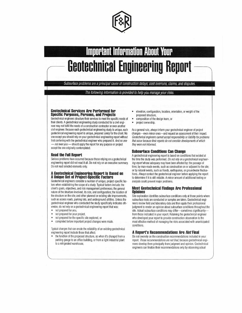
ASFE Publication “Important Information About Your Geotechnical Engineering Report”
APPENDIX B Site Vicinity Map (Drawing No. 1) Subsurface Exploration Plan (Drawing No.2)
APPENDIX C
Boring Logs (B-1 & B-2) Key to Boring Log Soil Classifications Unified Soil Classification System
APPENDIX D Laboratory Test Results

Environmental Engineering & Technology, Inc. Pump Station 60 Rehabilitation F&R Project No. 61P-0184 Newport News, Virginia F&R Report Serial No. P0184-GEO1 1 December 28, 2012
EXECUTIVE SUMMARY
This Executive Summary is provided as a brief overview of our geotechnical engineering evaluation for the project and is not intended to replace more detailed information contained elsewhere in this report. As an overview, this summary inherently omits details that could be very important to the proper application of the provided geotechnical design recommendations. This report should be read in its entirety prior to implementation into design and construction.
The project will consist of a new pump station building and wet well structure that will be constructed adjacent to the existing Pump Station 60. The building is expected to be a lightly loaded, one-story structure with a slab-on-grade near (±1’) the existing site grades. The wet well will be a reinforced concrete structure with a bottom slab at approximately 12 feet below the existing ground surface.
The pump station building may be supported by a conventional shallow spread foundation system bearing in approved natural soils or compacted controlled structural fill. Foundations may be designed for an allowable bearing pressure of 2,000 psf.
Site preparation at the pump station building will require the removal of existing uncontrolled fill material. This material was encountered to a depth of approximately two feet below the existing ground surface at the soil test boring location. The uncontrolled fill should be replaced with compacted controlled structural fill.
It is recommended that the excavation for the wet well structure be advanced to a depth to allow for the placement of a layer of #57 crushed stone directly beneath the slab in order to provide a suitable working base for construction. The crushed stone layer should have a minimum thickness of two feet and should be wrapped with geotextile fabric along the bottom and sides in order to reduce the potential for migration of surrounding natural soils into the stone.
The wet will excavation will be advanced to depths below the groundwater level. Dewatering of the excavation during construction will be necessary. The means and methods of dewatering should be selected by the contractor.

Environmental Engineering & Technology, Inc. Pump Station 60 Rehabilitation F&R Project No. 61P-0184 Newport News, Virginia F&R Report Serial No. P0184-GEO1 2 December 28, 2012
1.0 PURPOSE & SCOPE OF SERVICES
The purpose of the subsurface exploration and geotechnical engineering evaluation for this project was to 1) provide general descriptions of the subsurface soil conditions at the site, 2) provide groundwater elevation at the time of drilling, 3) provide foundation maximum allowable bearing capacity and lateral earth pressure coefficient recommendations, 4) provide general guidelines for the suitability of excavated soils for reuse as backfill, 5) provide a general discussion on excavation support related to the geotechnical aspects of the proposed construction, and 6) comment on the geotechnical aspects of the proposed construction. In order to accomplish the above objectives, we undertook the following scope of services:
• Visited the site to observe existing conditions, coordinated utility clearance, and marked the proposed boring locations.
• Coordinated utility clearance with Miss Utility
• Reviewed and summarized readily available geologic and subsurface information relative to the project site.
• Executed the subsurface exploration program consisting of two Standard Penetration Test (SPT) boring at the site in the location shown on the provided image. The borings were performed to a depth of 25 feet below ground surface.
• Performed a laboratory testing program on selected samples recovered from the site. A total of two soil classifications tests were performed (ASTM D422, D4318, and D2216).
• Prepared this written report summarizing our findings on the project providing general descriptions of subsurface conditions encountered, foundation design guidelines, groundwater considerations, and discussing geotechnical related aspects of the proposed construction.
Our scope of services did not include remediation (i.e., site restoration) other than backfilling boreholes with drilling spoils (soil materials), topographic or field surveying, development of quantity estimates, preparation of plans and specifications, or an environmental site assessment.
Environmental Engineering & Technology, Inc. Pump Station 60 Rehabilitation F&R Project No. 61P-0184 Newport News, Virginia F&R Report Serial No. P0184-GEO1 3 December 28, 2012
2.0 PROJECT INFORMATION
2.1 Site Location and Description
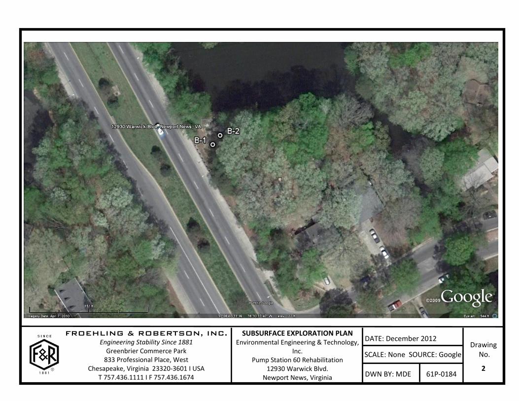
The project site is located at 12930 Warwick Blvd. in Newport News, Virginia, as shown on the Site Vicinity Map included in Appendix B as Drawing No. 1. The site is generally bounded by wooded areas, with a lake to the north and Warwick Blvd. to the southwest.
Existing Pump Station (PS) 60 is currently present at the project site. The new pump station will be located to the southeast of the existing PS 60. This area was generally flat and cleared, with piles of building debris. F&R understands that the ground surface in this area is at approximately Elev. +16.
2.2 Proposed Construction
The proposed construction will include a new pump station, which will consist of a building and wet well. F&R understands that the existing ground surface in the proposed building area is at approximately Elev. +16.
The building is expected to be a one-story masonry wall structure with a concrete slab-on-grade. The finished floor elevation is expected to be near (±1’) the existing site grades.
Wall loads for the building are anticipated to be on the order of 1,000 plf. Floor loads are expected to be less than 150 psf.
The wet well will be a reinforced concrete structure. F&R understands the base slab will be at Elev. +4.
3.0 EXPLORATION PROCEDURES
3.1 Subsurface Exploration
The subsurface exploration program consisted of two Standard Penetration Test (SPT) borings, designated as B-1 and B-2, at the approximate locations identified on the Subsurface Exploration Plan that is included in Appendix B as Drawing No. 2. The boring locations were marked at the site by representatives of F&R, Inc. Boring B-1 was performed at the approximate location of the wet well and Boring B-2 was performed at the approximate location of the building.

Environmental Engineering & Technology, Inc. Pump Station 60 Rehabilitation F&R Project No. 61P-0184 Newport News, Virginia F&R Report Serial No. P0184-GEO1 4 December 28, 2012
The test borings were performed on November 27, 2012, using a CME 55 track mounted drill rig equipped with an automatic hammer (i.e., hydraulic hammer). The borehole was advanced utilizing mud rotary drilling techniques. Standard Penetration Tests (SPT) were performed at the boring location in general accordance with ASTM D1586, continuously from the existing ground surface to a depth of ten feet, and at approximate five-foot depth intervals thereafter to the planned termination depth.
Soils samples were obtained with a standard 1.4” I.D., 2”O.D., and 30” long split-spoon sampler with each SPT being driven with a 140-lb manual automatic hammer falling 30 inches. The number of blows required to drive the sampler each 6-inch increment of penetration was recorded as Nfield at the time of sampling. The sum of the second and third penetration increments is termed the SPT value, “N.” The first six-inch increment is used to seat the sampler, and the sampler is often driven a fourth increment (after the SPT is completed) in order to obtain additional information that is used to stratify the soils. A representative portion of each disturbed split-spoon sample was collected with each SPT, placed in a glass jar, and returned to our laboratory for review.
An automatic hammer was used to perform the Standard Penetration Test (SPT) on this project. Research has shown that the Standard Penetration Resistance (N-value) determined by an automatic hammer is different than the N-value determined by the safety hammer method. Most correlations that are published in the technical literature are based on the N-value determined by the safety hammer method. This is commonly termed N60 as the rope and cathead with a safety hammer delivers about 60 percent of the theoretical energy delivered by a 140-pound hammer falling 30 inches.
Because an automatic hammer was used to perform the SPT tests, the sample blows recorded during drilling (Nfield) have been corrected to equivalent N60 safety hammer values. The N60 values reported on the boring logs included in this report were determined from the following equation:
N60 = Nfield x CE
A value of 1.3 was used for CE in accordance with guidelines provided in the Performance and Use of the Standard Penetration Test in Geotechnical Engineering Practice manual published by the Center for Geotechnical Practice and Research at the Virginia Polytechnic Institute and State University.
Environmental Engineering & Technology, Inc. Pump Station 60 Rehabilitation F&R Project No. 61P-0184 Newport News, Virginia F&R Report Serial No. P0184-GEO1 5 December 28, 2012
The recovered split-spoon samples were visually classified in accordance with ASTM D2488 by an F&R engineer at the time of drilling. Recovered split spoon samples were again reviewed in-house by an F&R senior engineer. The boring logs provided in Appendix C show the subsurface conditions encountered on the date and at the approximate locations indicated.
By the nature of the work performed, the drilling activities resulted in disturbances to the site. The completed boreholes were backfilled with auger cuttings and #3 sand prior to F&R departing the site. The borehole backfill may subside at some time following our work. F&R assumes no responsibility for borehole subsidence after completion of the field exploration and departing the site. For continued safety, the boreholes should be occasionally observed by others with any needed additional backfilling then being performed.
3.2 Laboratory Testing
A geotechnical laboratory testing program was performed on selected samples recovered from the site. The laboratory tests included two natural moisture content determinations (ASTM D2216) and two soil classification tests (ASTM D422 without hydrometer, D4318 and D2487). Laboratory test results are provided in Appendix D.
4.0 REGIONAL GEOLOGY & SUBSURFACE CONDITIONS
4.1 Regional Geology
The project site lies within the Coastal Plain physiographic province of Virginia, which extends from the Fall Zone eastward to the Atlantic Ocean.
Numerous transgressions and regressions of the Atlantic Ocean have deposited marine, lagoonal, and fluvial (stream lain) sediments. The regional geology is very complex, and generally consists of interbedded layers of varying mixtures of sands, silts, and clays.
4.2 Subsurface Conditions
The subsurface conditions discussed in the following sections and those shown on the boring logs represent an interpretation of the boring data using normally accepted geotechnical engineering judgment. The lines designating strata breaks on the borings logs represent approximate boundaries between soil types, as the transition may be gradual or may occur

Environmental Engineering & Technology, Inc. Pump Station 60 Rehabilitation F&R Project No. 61P-0184 Newport News, Virginia F&R Report Serial No. P0184-GEO1 6 December 28, 2012
between samples. The transitions between different soil strata are usually less distinct than those shown on the boring logs.
4.2.1 Generalized Subsurface Stratigraphy
The subsurface conditions presented by the following Figure 1 are our interpretation of the general soil stratigraphy and subsurface conditions at the boring locations at the project site. The interpretation necessarily assumes uniform subsurface conditions across the site, which is probably, but not necessarily, correct. The subsurface conditions may also change with time and groundwater fluctuations. The conditions presented in Figure 1 provide general descriptions of subsurface soil conditions and should not be considered as a substitute for the boring log that is included in Appendix C of this report.
Figure 1 – Subsurface Profile
Figure 1 Notes
• SURFACE: #3 Ballast Stone and Medium-Dense, Brown, Clayey Fine SAND with trace gravel (Fill-SC)
• STRATUM I: Very Stiff to Stiff, Reddish Brown, Fine Sandy CLAY (CL)

Environmental Engineering & Technology, Inc. Pump Station 60 Rehabilitation F&R Project No. 61P-0184 Newport News, Virginia F&R Report Serial No. P0184-GEO1 7 December 28, 2012
• STRATUM II: Medium-Dense, Reddish Brown, Silty Fine SAND (SM), Loose, Light Gray Mottled Reddish Brown, Silty Fine SAND with little clay SM)
• STRATUM III: Loose, Gray Mottled Reddish Brown, Fine Sandy CLAY (CL) • STRATUM IV: Loose, Reddish Brown Mottled Red, Fine SAND with little silt (SP-SM),
Loose, Gray, Silty Fine SAND (SM) • STRATUM V: Very Soft, Gray, CLAY with little fine sand (CL)
4.2.2 Surface Materials
Surficial Material was encountered in the boring to approximate depths of two feet below the existing ground surface. This approximate depth is based on driller observations and not a measured depth and should be expected to vary across the site. Surface Materials consisted of #3 ballast stone and a fill material consisting of medium-dense, brown, clayey fine sand with trace gravel. Actual Surface Material depths should be expected to vary across the site.
4.2.3 Subsurface Water
Groundwater was judged to have been encountered at a depth of approximately eight feet below the existing ground surface at the time of drilling operations as noted on the boring logs. Groundwater levels may fluctuate with seasonal changes, periods of heavy or little rainfall, pumping from wells, and other factors. Therefore, our field measurements do not reveal the actual year-round groundwater conditions.
5.0 GEOTECHNICAL DESIGN RECOMMENDATIONS
5.1 General
The following evaluations and recommendations are based on our observations at the site, interpretation of the field and laboratory data obtained during our subsurface exploration, and our experience with similar subsurface conditions and projects. Subsurface conditions in unexplored locations may vary from those encountered. If the locations are changed, we request that we be advised so that we may re-evaluate our recommendations.
Determination of an appropriate foundation system for a given structure is dependent on the proposed structural loads, soil conditions, and construction constraints such as proximity to other structures, etc. The subsurface exploration aids the geotechnical engineer in determining the soil stratum appropriate for structural support. This determination includes considerations with

Environmental Engineering & Technology, Inc. Pump Station 60 Rehabilitation F&R Project No. 61P-0184 Newport News, Virginia F&R Report Serial No. P0184-GEO1 8 December 28, 2012
regard to both allowable bearing capacity and compressibility of the soil strata. In addition, consideration must be given to the implementation of suitable methods of site preparation, fill compaction, and other aspects of construction.
5.2 Building Foundation Design Recommendations
Based on the available project information and our evaluations, the proposed building may be supported by conventional shallow foundations bearing in approved natural Stratum I soils or controlled structural fill placed in accordance with the requirements of Section 6.4.
We recommend that foundations be designed for a maximum net allowable bearing pressure of 2,000 pounds per square foot (psf). Lightly loaded independent continuous wall foundations should have a minimum width of 18 inches to reduce possibility of a “punching” shear failure. The structural elements should be centered on the foundations to provide a uniform load transfer, unless the foundations are proportioned for eccentric loads.
Foundations should be at a depth of at least 18 inches below the finished exterior site grades to lessen the potential for damage from frost penetration for bearing capacity considerations.
5.2.1 Building Slab-on-Grade Recommendations
A slab-on-grade may be supported by approved Stratum I or II soils following site preparation procedures as recommended in Section 6.2 of this report. A standard modulus of subgrade reaction (“k”) of 200 pci may be used for the design of the slab.
A six-inch thick layer of Virginia Department of Transportation (VDOT) No. 57 or No.78 open-graded coarse aggregate or clean sand (SP per the Unified Soil Classification System) should be placed beneath the floor slab. This granular base would function as a leveling and load distributing material as well as a capillary break beneath the slab.
A vapor retarder should be used beneath the buildings floor slabs that will be covered by tile, wood, carpet, impermeable floor coatings, and/or if other moisture-sensitive equipment or materials will be in contact with the floor. However, the use of vapor retarders may result in excessive curling of floor slabs during curing. We refer the floor slab designer to ACI 302.1R-96, Sections 4.1.5 and 11.11, for further discussion on vapor retarders, curling, and the means to lessen potential concrete shrinkage and curling.

Environmental Engineering & Technology, Inc. Pump Station 60 Rehabilitation F&R Project No. 61P-0184 Newport News, Virginia F&R Report Serial No. P0184-GEO1 9 December 28, 2012
5.2.2 Anticipated Shallow Foundation and Floor Slab Settlement
Based on the boring data and the project information provided in Section 2.2, the total settlement of continuous wall footings loaded to 1 kip per lineal foot, and floor slab loaded to 150 psf, is expected to on the order of ½-inch or less. Differential foundation settlement is anticipated to be on the order one-half of the total settlement, or less.
The magnitude of different settlements will be influenced by the variation in excavation requirements across the footprint of the structure, the distribution of loads, level of uniform compaction of structural fill, and the variability of underlying soils.
Our settlement analysis was performed on the basis of structural grading assumptions discussed in the project information section of this report. Actual settlements experienced by the structure and the time required for these soils to settle will be influenced by undetected variations in subsurface conditions, actual structural loads, final grading plans, and the quality of fill placement and foundation construction.
5.3 Wet Well Foundation Design Recommendations
The wet well foundation slab is expected to bear in the Stratum IV material with the top of slab at a depth of approximately 12 feet below the existing ground surface (Elev. 4). In order to provide a stable base for bearing and construction of the wet well slab/mat foundation, and to aid in construction dewatering, it is recommended that the excavation be advanced such that a two foot thick (minimum) layer of VDOT #57 crushed stone can be placed directly beneath the slab/mat and bear into Stratum IV material. Stratum IV material is a loose sand with little silt. The stone should be wrapped on the bottom and sides with geotextile fabric to limit migration of the stone into the surrounding Stratum IV material.
The maximum foundation unit loading is expected to occur during construction while the excavation is dewatered. In order to provide suitable bearing capacity, the excavation should be widened to allow for the placement of the VDOT #57 crushed stone layer to extend a minimum of two feet horizontally past the edges of the foundation slab. Utilizing this design, and following the foundation construction recommendations provided in Section 6.3 of this report, a short term foundation loading of 2,000 psf may be applied to the top surface of the VDOT #57 crushed stone layer. Substantial settlement due to consolidation of the foundation bearing soils is not anticipated to occur during short-term loading events.
Environmental Engineering & Technology, Inc. Pump Station 60 Rehabilitation F&R Project No. 61P-0184 Newport News, Virginia F&R Report Serial No. P0184-GEO1 10 December 28, 2012
Due to potential fluctuations of the groundwater, the wet well should be designed to resist long-term post-construction hydrostatic uplift pressures based on a groundwater level at the ground surface.
5.3.1 Anticipated Wet Well Foundation Settlements
The long-term net loading of the slab/mat foundation for the wet well is expected to be less than the effective weight of the soils that will be removed for the construction of the wet well. As such, settlement of the wet well foundation is expected to be limited to the rebound of the foundation soil due to the removal of the overburden soil, and the subsequent reloading of the foundation soil due to the loads imposed by the wet well foundation. This settlement is expected to be on the order of ½-inch, or less.
5.4 Lateral Earth Pressures
The following information is provided to aid in analysis of soil loads on below-grade concrete structures. These below-grade wall recommendations should not be correlated for use in any other wall design.
Earth pressures on below grade walls are influenced by structural design of the walls, conditions of wall restraint, methods of construction and/or compaction, and the strength of the materials being restrained. The most common conditions assumed for earth retaining wall design are the active and at-rest conditions. Active conditions apply to relatively flexible earth retention structures, such as freestanding walls, where some movement and rotation may occur to mobilize soil shear strength. Walls that are rigidly restrained, such as expected for the wet well walls, require design using at-rest earth pressures.
A third condition, the passive state, represents the maximum possible pressure when a structure is pushed against the soil, and is used in wall foundation design to help resist active or at-rest pressures. Because significant wall movements are required to develop the passive pressure, the total calculated passive pressure should be reduced by one-half to two-thirds for design purposes.
A granular material should be used for backfill beside the below grade wet well walls. This material should meet the requirements for controlled structural fill, as outlined in Section 6.4 of this report.

Environmental Engineering & Technology, Inc. Pump Station 60 Rehabilitation F&R Project No. 61P-0184 Newport News, Virginia F&R Report Serial No. P0184-GEO1 11 December 28, 2012
A moist unit weight of 120 pounds per cubic foot and angle of internal friction of 30° should be used for design calculations for below grade walls backfilled with approved granular materials. Based on these values, recommended lateral earth pressure coefficients and equivalent fluid pressure parameters for design of below grade walls using granular backfill are provided in the following Table 2.
Table 2 - Lateral Earth Pressure Design Data
Granular Backfill / Stratum III Sand
Earth Pressure
Conditions Coefficient Recommended Equivalent Fluid
Pressure - Drained (psf/ft)1
Fully Submerged Equivalent Fluid Pressures
(psf/ft)1 Active (Ka) 0.33 40 81 At-Rest(Ko) 0.50 60 91 Passive (Kp) 3.00 360 --
NOTE: 1 – does not include a factor of safety
5.5 Expansive Soil Evaluation
The existing subgrade soils encountered by the soil test borings were evaluated for shrink-swell (expansion) potential within the active zone, which typically extends to a depth of approximately three to four feet below the ground surface in the region of the proposed site.
The existing soils within the active zone appear to be generally classified as sandy lean clay in accordance with the Unified Soil Classification System. The observed soils in the active zone are judged to be of low to moderate plasticity.
Based on correlations provided in geotechnical literature, the soil samples within the active zone are judged to have a low to moderate potential for shrink-swell activity. It is noted that the wet well structural elements will be bearing below the active zone. As a result, it is anticipated that the proposed construction will not be significantly influenced by expansive soil conditions.
5.6 Seismic Design Criteria
Section 1613.5.2 of the 2009 International Building Code (IBC) provides guidelines for determining the seismic Site Class, based on soil properties present within the upper 100 feet
Environmental Engineering & Technology, Inc. Pump Station 60 Rehabilitation F&R Project No. 61P-0184 Newport News, Virginia F&R Report Serial No. P0184-GEO1 12 December 28, 2012
of the subsurface profile. It is noted that the borings for the project were terminated at depths of 25 feet, which was sufficient for foundation bearing capacity and settlement evaluations. IBC notes that when soil properties are not known in sufficient detail, then a Site Class D shall be used unless Site Class E or F soil is likely to be present at the site.
Based on the data obtained from the soil borings, a Site Class D is appropriate for this site. Thus F&R recommends that a site Class D be used for further evaluations relative to earthquake load design.
We note that the above provided soil Site Classification is based on information available at the time this report was written. Should this classification be so onerous to the project cost that further study is warranted, we can perform a site-specific geo-physical survey to attain sufficient detail to further define the project’s soil Seismic Site Class Definition. This additional testing would be beyond the currently authorized scope of services for this project.
6.0 GEOTECHNICAL CONSTRUCTION RECOMMENDATIONS
6.1 General
The principal purpose of this section is to comment in general on the items related to the construction and geotechnical engineering aspects of construction that should be expected for this project. It is recommended that the geotechnical engineer be retained to provide soil engineering services during the actual site preparation, construction, and pavement construction phases of the project, to perform appropriate evaluations to help assure that conditions encountered during the project are similar to conditions encountered in the borings. The geotechnical engineer can also assist in interpretation of differing subsurface conditions that may be encountered and recommend remedial work, if needed.
6.2 Site Preparation – Building Area
Site preparation for the building should include the complete removal of ballast stone, gravel fill, surface vegetation, surficial soils, organic materials, trees, tree stumps, roots, and organic soils. The depth of removal of these materials is typically expected to be on the order of two feet below the existing ground surface.
The near surface subgrade soils at the site may lose stability if these soils become wet and are subjected to construction traffic. As a result, site preparation should be performed during an
Environmental Engineering & Technology, Inc. Pump Station 60 Rehabilitation F&R Project No. 61P-0184 Newport News, Virginia F&R Report Serial No. P0184-GEO1 13 December 28, 2012
extended period of dry weather. Any fill materials, aggregate, and/or concrete should be placed as soon as possible over the approved subgrade in order to reduce exposure of the subgrade to weather and construction activity. It is important to stress that if site preparation/construction is performed during the winter months, extensive undercutting may be required if the subgrade is not properly prepared/protected.
Upon completion of stripping operations, the geotechnical engineer should observe exposed subgrade of the building area. The purpose of observing is to detect any soft areas and to evaluate the general stability of the near surface subgrade soils. Any areas that are judged unsuitable during observation should be over excavated to firm material and be replaced with compacted structural fill, as recommended by the geotechnical engineer and as directed by the Owner.
Concrete should not be placed on frozen or saturated subgrades. If such materials are allowed to remain below foundations, settlements will increase. Foundation excavations should be concreted as soon as practical after they are excavated. If an excavation is left open for an extended period, a thin mat of lean concrete should be placed over the bottom to minimize damage to the bearing surface from weather or construction activities. Water should not be allowed to pond in any excavation.
Site drainage will be important throughout sitework operations, during which positive drainage away from the areas undergoing development should be maintained to reduce potential for deterioration of the exposed soil subgrade.
Shallow foundation subgrades should be observed, evaluated, and verified for the design bearing pressure by the geotechnical engineer after excavation and prior to reinforcement steel placement. If low consistency soils are encountered during foundation construction, localized undercutting and/or in-place stabilization of foundation subgrades will be required. The actual need for, and extent of, undercutting should be based on field observations made by the geotechnical engineer at the time of construction.
Excavations for footings should be made in such a way as to provide bearing surfaces that are firm and free of loose, soft, wet or otherwise disturbed soils. Foundation concrete should not be placed on frozen or saturated subgrades. If such materials are allowed to remain below foundations, settlements will increase. Foundation excavations should be concreted as soon as practical after they are excavated. If an excavation is left open for an extended period, a thin mat of lean concrete should be placed over the bottom to lessen potential damage to the

Environmental Engineering & Technology, Inc. Pump Station 60 Rehabilitation F&R Project No. 61P-0184 Newport News, Virginia F&R Report Serial No. P0184-GEO1 14 December 28, 2012
bearing surface water or construction activities. Water should not be allowed to pond in any excavation.
6.3 Foundation Construction for Wet Well
Foundation subgrade for the wet well should be observed, evaluated, and verified by the geotechnical engineer for consistency with the soils encountered by the soil boring. These observations should be performed after the excavation is completed but prior to placement of the recommended stone layer.
The foundation bearing soils will be sensitive to disturbance due to construction activities, and will lose stability if high disturbed. Any soils that become excessively disturbed during the excavation procedures should be undercut and replaced with a thickened layer of VDOT #57 crushed stone, as recommended by the geotechnical engineer and as directed by the Owner.
In order to reduce potential excessive disturbance for the foundation bearing soils, it is recommended that the geotextile fabric and VDOT #57 crushed stone be placed immediately following foundation observations and approval by the geotechnical engineer. VDOT #57 crushed stone should be seated in-place to a non-yielding condition using the bucket of the excavation equipment.
6.4 Controlled Structural Fill
Controlled structural fill material for the building pad and backfill behind walls should be non-expansive and free of organic matter, debris, and particles larger than two inches in size. Proposed fill material should be subjected to laboratory tests consisting of, but not necessarily limited to, moisture density determinations (ASTM D698), Atterberg limits (ASTM D4318), and sieve analysis (ASTM D422). These tests are needed for quality control during compaction and to determine if the fill material is acceptable. Controlled structural fill should classify per the Unified Soil Classification System (USCS) as SW, SP, SP-SM, or SM with a maximum of 15 percent fines passing the No. 200 sieve. Coal combustion by-products are not suitable for use as controlled structural fill.
Fill materials should be placed in horizontal lifts with maximum height of 12 inches loose measure and compacted with a vibratory compactor operating in vibratory mode. In confined areas such as utility trenches or adjacent to the wet well walls, portable compaction equipment and thin lifts of 3 inches to 4 inches may be required to achieve specified degrees of compaction.

Environmental Engineering & Technology, Inc. Pump Station 60 Rehabilitation F&R Project No. 61P-0184 Newport News, Virginia F&R Report Serial No. P0184-GEO1 15 December 28, 2012
The structural fill should be compacted to at least 95 percent of the standard Proctor (ASTM D698) maximum dry density in areas where structures are to be supported. The compaction requirement may be reduced to a minimum of 90 percent in green areas. In general, we recommend that the moisture content of fill soils be maintained within three percentage points of the optimum moisture content as determined from the standard Proctor maximum dry density test. Excessively wet or excessively dry soils should not be used as fill material without proper drying or wetting. We recommend that the contractor have equipment on site during earthwork for both drying and wetting of fill soils.
Each lift of fill should be tested in order to confirm that the recommended degree of compaction is attained. Field density tests to verify fill compaction should be performed at an appropriate frequency for the area being tested, with a minimum of three tests per lift. In confined areas, such as trench backfill, a greater frequency may be required. Testing areas may be increased and the frequencies reduced based on the size of the structure and discretion of the geotechnical engineer.
6.5 Reuse of Existing Soils for Controlled Structural Fill or Backfill
Excavated Surface, Stratum I, II, and III, soils are not suitable for reuse as controlled structural fill. It is recommended that an allowance for imported fill from an offsite source be a project requirement.
Excavated Stratum IV soils may be reused as controlled structural fill. However, minimal volume of Stratum IV soils is expected to be removed. Stratum IV materials would need to be segregated from Stratum III materials and allowed to dry. Stratum IV materials when initially excavated will be saturated.
6.6 Excavation Bracing
It is expected that the excavation for the wet well will be braced with a sheet pile system. Design of the sheet pile bracing system should be the responsibility of the contractor. The sheet pile bracing design should be sealed by a professional engineer licensed in the Commonwealth of Virginia.
6.7 Groundwater Conditions / Dewatering
Groundwater for the purpose of this report is defined as water encountered below the existing ground surface. Based on the data obtained from the soil test borings, groundwater was

Environmental Engineering & Technology, Inc. Pump Station 60 Rehabilitation F&R Project No. 61P-0184 Newport News, Virginia F&R Report Serial No. P0184-GEO1 16 December 28, 2012
encountered at a depth of approximately eight feet below the existing ground surface at the time of the subsurface exploration.
Dewatering for the wet well excavation will be necessary. Dewatering on similar projects has typically been accomplished with sump and pump methods; however, the selection and design of the dewatering system should be the responsibility of the contractor.
7.0 CONTINUATION OF SERVICES
We recommend that we be given the opportunity to review the grading plan and project specifications when construction documents approach completion. This review evaluates whether the recommendations and comments provided herein have been understood and properly implemented. We also recommend that Froehling & Robertson, Inc., be retained for professional and construction materials testing services during construction of the project. Our continued involvement on the project helps provide continuity for proper implementation of the recommendations discussed herein.
It should be noted that the actual soil conditions at the various depths may vary across this site and thus the presence of the Geotechnical Engineer and/or his representative during construction will serve to validate the subsurface conditions and recommendations presented in this report. We recommend that F&R be employed to monitor the earthwork and foundation construction, and to report that the recommendations contained in this report are completed in a satisfactory manner. Our involvement on the project will aid in the proper implementation of the recommendations discussed herein.
Environmental Engineering & Technology, Inc. Pump Station 60 Rehabilitation F&R Project No. 61P-0184 Newport News, Virginia F&R Report Serial No. P0184-GEO1 17 December 28, 2012
8.0 LIMITATIONS
There are important limitations to this and all geotechnical studies. Some of these limitations are discussed in the information prepared by The Association of Engineering Firms Practicing in the Geoscience (ASFE), which is included in Appendix A. We recommend that you review the ASFE information.
This report has been prepared for the exclusive use of Environmental Engineering & Technology, Inc., or their agents for the specific application to the Pump Station 60 Rehabilitation located in Newport News, Virginia, in accordance with generally accepted soil and foundation engineering practices. No other warranty, express or implied, is made.
Our conclusions and recommendations are based on design information furnished to us at the time the work was performed, the data obtained from the previously described subsurface exploration program, and generally accepted geotechnical engineering practice. The findings and recommendations do not reflect variations in subsurface conditions, which could exist in unexplored areas of the site. In areas where variations from the available subsurface data become apparent during construction, it will be necessary to re-evaluate our conclusions and recommendations based upon on-site observations of the conditions.
Regardless of the thoroughness of a subsurface exploration, there is the possibility that conditions in other areas will differ from those at the boring location, that conditions are not as anticipated by the designers, or that the construction process has altered the soil conditions. Therefore, our experienced geotechnical engineers should evaluate foundation construction to verify that the conditions anticipated in design actually exist. Otherwise, we assume no responsibility for construction compliance with the design concepts, specifications, or recommendations.
In the event that changes are made in the design or location of the proposed project, the recommendations presented in this report shall not be considered valid unless the changes are reviewed by our firm and conclusions of this report modified and/or verified in writing. If this report is copied or transmitted to a third party, it must be copied or transmitted in its entirety, including text, attachments, and enclosures. Interpretations based on only a part of this report may not be valid.

APPENDIX A
ASFE Publication “Important Information About Your Geotechnical Engineering Report”


APPENDIX B
Site Vicinity Map (Drawing No. 1) Subsurface Exploration Plan (Drawing No. 2)

FROEHLING & ROBERTSON, INC. Engineering Stability Since 1881
Greenbrier Commerce Park 833 Professional Place, West
Chesapeake, Virginia 23320-3601 I USA T 757.436.1111 I F 757.436.1674
DATE: December 2012
SCALE: As Shown
EDITED: MDE
Site Vicinity Map Environmental Engineering & Technology, Inc..
Pump Station 60 Rehabilitation Newport News, Virginia
Drawing No. 1
61P-0184
DATE: December 2012 SCALE: None SOURCE: Google
DWN BY: MDE 61P-0184
SUBSURFACE EXPLORATION PLAN Environmental Engineering & Technology,
Inc. Pump Station 60 Rehabilitation
12930 Warwick Blvd. Newport News, Virginia
Drawing No.
2
FROEHLING & ROBERTSON, INC. Engineering Stability Since 1881
Greenbrier Commerce Park 833 Professional Place, West
Chesapeake, Virginia 23320-3601 I USA T 757.436.1111 I F 757.436.1674

APPENDIX C
Subsurface Profile Boring Logs (B-1 & B-2)
Key to Boring Log Soil Classification Unified Soil Classification System

SUBSURFACE PROFILE
-8
-6
-4
Profile Name: Subsurface Profile
Elev
atio
n (f
t)
Plot Based on Elevation
City/State: Newport News, VirginiaProject: Pump Station 60Client: EE&T, Inc.
Froehling & Robertson, Inc.
Project No: 61P-0184
R
ELEV
_LAN
DSC
APE_
8.5X
11 6
1P-0
184.
GPJ
F&
R.G
DT
12/
26/1
2
See the boring logs in Appendix III for a description of the graphic symbols and soil coassificationGroundwater level at time of drilling
* Standard Penetration Resistance, N60Subsurface Profile Notes:
-2
0
2
4
6
8
10
12
14
16
Stratum VStratum V Stratum V
Stratum I Stratum I
SurfaceSurface
Stratum I
Stratum IV Stratum IV Stratum IV
Stratum IIIStratum III
Stratum II
Stratum IIStratum II
Surface
1
6
7
9
15
16
14
16B-1 B-2
**
6
9
10
14
24
16
12

2.0
4.0
6.0
8.0
10.0
15.0
20.0
25.0
4-8-8-4
7-7-7-7
7-8-8-8
8-8-7-7
8-4-5-5
3-3-4-3
8-3-3-3
**-**-1-3
#3 Ballast StoneSURFACEMedium-Dense, Brown, Clayey Fine SAND withtrace gravel, dry (Fill-SC)SURFACEVery Stiff to Stiff, Reddish Brown to ReddishBrown Mottled Gray, Fine Sandy CLAY, moist (CL)STRATUM I
Medium-Dense, Reddish Brown, Silty Fine SAND,moist (SM)STRATUM II
Stiff, Gray Mottled Reddish Brown, Fine SandyCLAY, wet (CL)STRATUM III
Loose, Reddish Brown to Tan, Fine to CoarseSAND with little silt, wet (SP-SM)STRATUM IV
Loose, Gray, Silty Fine to Medium SAND, wet(SM)STRATUM IV
Very Soft, Gray, CLAY with little fine sand, wet(CL)STRATUM V
Boring Terminated at 25 Feet
15.8
14.0
10.0
8.0
4.0
-1.0
-6.0
-9.0
0.2
2.0
6.0
8.0
12.0
17.0
22.0
25.0
0.0
2.0
4.0
6.0
8.0
13.0
18.0
23.0
Groundwater wasencountered at a depth ofapproximately 8 feetduring drilling.
** - Weight of Hammer
* - Sample Blows obtainedwith an AutomaticHammer. ReportedSample Blows have beencorrected to equivalentN60 energy.
16
14
16
15
9
7
6
1
Elevation: 16 ± Drilling Method: Mud RotaryHammer Type: Automatic
Froehling & Robertson, Inc.
Client: EE&T, Inc.
City/State: Newport News, VAProject: Pump Station 60 Rehabilitation
Project No: 61P-0184Total Depth: 25.0'Boring Location: See F&R Dwg. No. 2
BORING LOGBoring: B-1 (1 of 1)
N-Value(blows/ft)
Driller: FDI
SampleDepth(feet)
Depth
R
* SampleBlowsElevation RemarksDescription of Materials
(Classification)
Date Drilled: 11/27/12
*Number of blows required for a 140 lb hammer dropping 30" to drive 2" O.D., 1.375" I.D. sampler a total of 24 inches in four 6" increments. Thesum of the second and third increments of penetration is termed the standard penetration resistance, N-Value.
BORI
NG
_LO
G 6
1P-0
184.
GPJ
F&
R.G
DT
12/
28/1
2

2.0
4.0
6.0
8.0
10.0
15.0
20.0
25.0
9-7-5-8
10-8-8-7
8-12-12-10
8-7-7-5
4-7-3-4
7-5-4-5
9-3-3-3
**-**-**-1
#3 Ballast StoneSURFACEMedium-Dense, Brown, Clayey Fine SAND withtrace gravel, dry (Fill-SC)SURFACEVery Stiff, Reddish Brown, Fine Sandy CLAY,moist (CL)STRATUM I
Medium-Dense, Reddish brown, Silty Fine toMedium SAND, moist (SM)STRATUM II
Loose, Light Gray Mottled Reddish Brown, SiltyFine to Medium SAND with little clay, wet (SM)STRATUM II
Loose, Reddish Brown Mottled Red, Fine toCoarse SAND with little silt, wet (SP-SM)STRATUM IV
Loose, Gray, Silty Fine to Medium SAND, wet(SM)STRATUM IV
Very Soft, Gray, CLAY with little fine sand, wet(CL/CH)STRATUM V
Boring Terminated at 25 Feet
15.7
14.0
10.0
8.0
4.0
-1.0
-6.0
-9.0
0.3
2.0
6.0
8.0
12.0
17.0
22.0
25.0
0.0
2.0
4.0
6.0
8.0
13.0
18.0
23.0
No Recovery from 0' to 2'
Groundwater wasencountered at a depth ofapproximately 8 feetduring drilling.
** - Weight of Hammer
* - Sample Blows obtainedwith an AutomaticHammer. ReportedSample Blows have beencorrected to equivalentN60 energy.
12
16
24
14
10
9
6
0
Elevation: 16 ± Drilling Method: Mud RotaryHammer Type: Automatic
Froehling & Robertson, Inc.
Client: EE&T, Inc.
City/State: Newport News, VAProject: Pump Station 60 Rehabilitation
Project No: 61P-0184Total Depth: 25.0'Boring Location: See F&R Dwg. No. 2
BORING LOGBoring: B-2 (1 of 1)
N-Value(blows/ft)
Driller: FDI
SampleDepth(feet)
Depth
R
* SampleBlowsElevation RemarksDescription of Materials
(Classification)
Date Drilled: 11/27/12
*Number of blows required for a 140 lb hammer dropping 30" to drive 2" O.D., 1.375" I.D. sampler a total of 24 inches in four 6" increments. Thesum of the second and third increments of penetration is termed the standard penetration resistance, N-Value.
BORI
NG
_LO
G 6
1P-0
184.
GPJ
F&
R.G
DT
12/
28/1
2

KEY TO BORING LOG SOIL CLASSIFICATIONS Particle Size and Proportion Verbal descriptions are assigned to each soil sample or stratum based on estimates of the particle size of each component of the soil and the percentage of each component of the soil.
Particle Size Proportion/
Descriptive Terms Descriptive Terms
Soil Component Particle Size Component Term Percentage
Boulder Cobble
Gravel-Coarse -Fine
Sand-Coarse -Medium
-Fine Silt (non-cohesive)
Clay (cohesive)
> 12 inch 3 - 12 inch 3/4 - 3 inch #4 - 3/4 inch #10 - #4 #40 - #10 #200 - #40 < #200 < #200
Major
Secondary
Minor
Uppercase Letters (e.g., SAND, CLAY)
Adjective
(e.g., sandy, clayey)
Some Little Trace
> 50% 20%-50% 15%-25% 5%-15% 0%-5%
Notes: 1. Particle size is designated by U.S. Standard Sieve Sizes. 2. Because of the small size of the split-spoon sampler relative to the size of gravel, the true percentage of gravel may not be accurately estimated.
Density or Consistency The standard penetration resistance values (N-values) are used to describe the density of coarse-grained soils (GRAVEL, SAND) or the consistency of fine-grained soils (SILT, CLAY). Sandy silts of very low plasticity may be assigned a density instead of a consistency.
DENSITY CONSISTENCY
Term N-Value Term N-Value
Very Loose Loose
Medium-Dense Dense
Very Dense
0 - 4 5 - 10 11 - 30 31 - 50 > 50
Very Soft Soft
Firm Stiff
Very Stiff Hard
0 - 1 2 - 4 5 - 8 9 - 15 16 - 30 > 30
Notes: 1. The N-value is the number of blows of a 140 lb. Hammer freely falling 30 inches required to drive a standard split spoon sampler (2.0 in. O.D., 1 3/8 in. I.D.) 12 inches into the soil after properly seating the sampler six inches. 2. When encountered, gravel may increase the N-value of the standard penetration test and may not accurately represent the in-situ density or consistency of the soil sample.
Rev. APR 2005 rev. APR 2005

APPENDIX D
Laboratory Test Results

0
5
10
15
20
25
30
35
40
45
50
55
60
65
70
75
80
85
90
95
100
0.0010.010.1110100Grain Size (mm)
GRAIN SIZEDISTRIBUTION
COBBLES
3/8 3 4 6 810 1416 20 30 40 50 60 100140200
Perc
ent F
iner
(By
Wei
ght)
GRAVELcoarse fine coarse medium
SANDfine
SILT OR CLAY
Boring No. DepthB-1B-2
atatatatat
13.02.0
ClassificationPOORLY GRADED SAND with SILT (SP-SM)
SANDY LEAN CLAY (CL)
LLNP36
PLNP17
PINP19
0.2450.08
D30 D10
3.38Cc
1.27
U.S. SIEVE OPENING IN INCHES
Boring No. DepthB-1B-2
atatatatat
13.02.0
D1004.7512.5
D600.15
%Gravel0.02.7
%Sand88.940.3
%Silt %Clay10.957.0
Cu
U.S. SIEVE NUMBERS HYDROMETER
6 4 3 2 1.5 1 3/4 1/2
Client: EE&T, Inc.
City/State: Newport News, VAProject: Pump Station 60 Rehabilitation
Project No: 61P-0184
R
Froehling & Robertson, Inc.U
S_G
RAIN
_SIZ
E 6
1P-0
184.
GPJ
F&
R.G
DT
12/
26/1
2

B-1 13.0 NP NP NP 24.9 0.0 88.9 10.9 SP-SM A-2-4B-2 2.0 36 17 19 15.3 2.7 40.3 57.0 CL A-6
Sheet: 1 of 1
AASHTOClass.
%Gravel
%Sand
%Fines
USCSClass.
LABORATORY TESTSUMMARY SHEET
CBRValue@ 0.1
Boring/Sample No. LL PL PI Water
Content (%)Optimum
WaterContent (%)
MaximumDry Density
(pcf)Depth (ft)
City/State: Newport News, VAProject: Pump Station 60 RehabilitationClient: EE&T, Inc.
Froehling & Robertson, Inc.
Project No: 61P-0184
R
LAB
SUM
MAR
Y 6
1P-0
184.
GPJ
F&
R.G
DT
12/
26/1
2

HQ: 3015 DUMBARTON ROAD RICHMOND, VIRGINIA 23228 T 804.264.2701 F 804.264.1202 www.fandr.com
VIRGINIA • NORTH CAROLINA • SOUTH CAROLINA • MARYLAND • DISTRICT OF COLUMBIA