report chair of applied dynamics april 2011 – december 2012 · · 2015-07-21chair of applied...
TRANSCRIPT

Chair of Applied Dynamics
Report
April 2011 – December 2012
Lehrstuhl fürTechnische DynamikProf. Dr.-Ing. habil. Sigrid Leyendecker

c© 2012Prof. Dr.-Ing. habil. S. LeyendeckerLehrstuhl fur Technische DynamikUniversitat Erlangen-NurnbergKonrad-Zuse-Str. 3/591058 ErlangenTel.: 09131 8561000Fax.: 09131 8561011www: http://www.ltd.tf.uni-erlangen.de
Editor: N. Kondratieva
All rights reserved. Without explicit permission of the authors it is not allowed to copythis publication or parts of it, neither by photocopy nor in electronic media.

Contents
1 Preface 4
2 Team 5
3 Research 73.1 Emmy Noether Independent Junior Research Group . . . . . . . . . . . . . . . . . . . 73.2 Bionicum . . . . . . . . . . . . . . . . . . . . . . . . . . . . . . . . . . . . . . . . . . . 73.3 Cooperation partners . . . . . . . . . . . . . . . . . . . . . . . . . . . . . . . . . . . . . 73.4 Scientific reports . . . . . . . . . . . . . . . . . . . . . . . . . . . . . . . . . . . . . . . 8
4 Activities 264.1 Teaching . . . . . . . . . . . . . . . . . . . . . . . . . . . . . . . . . . . . . . . . . . . . 264.2 Theses . . . . . . . . . . . . . . . . . . . . . . . . . . . . . . . . . . . . . . . . . . . . . 274.3 Seminar for Mechanics . . . . . . . . . . . . . . . . . . . . . . . . . . . . . . . . . . . 284.4 Press releases . . . . . . . . . . . . . . . . . . . . . . . . . . . . . . . . . . . . . . . . . 32
5 Publications 355.1 Reviewed journal publications . . . . . . . . . . . . . . . . . . . . . . . . . . . . . . . . 355.2 Reviewed proceeding publications . . . . . . . . . . . . . . . . . . . . . . . . . . . . . . 355.3 Talks . . . . . . . . . . . . . . . . . . . . . . . . . . . . . . . . . . . . . . . . . . . . . . 37
6 Social events 40

1 Preface
1 Preface
This report summarises the activities in research and teaching of the Chair of Applied Dynamics atthe University of Erlangen-Nuremberg between April 2011 and December 2012. The Chair of AppliedDynamics (Lehrstuhl fur Technische Dynamik LTD) started in April 2011 as a new chair at theUniversity of Erlangen-Nuremberg.Part of LTD is the Independent Junior Research Group in the DFG Emmy Noether Programme‘Simulation and optimal control of the dynamics of multibody systems in biomechanics and robotics’that has been at the University of Kaiserslautern from May 2009 to March 2011. Research topics aresituated in the field of computational mechanics, in particular dynamics and applied mathematicswith focus on the simulation of human motion (everyday movements and sports) and robot dynamicsas well as the optimization and optimal control of their dynamics.
Sigrid Leyendecker
Chair of Applied Dynamics, Report April 2011 – December 2012 4

2 Team
2 Team
chair holderProf. Dr.-Ing. habil. Sigrid Leyendecker
technical staffBeate HegenDipl.-Ing. (FH) Natalia KondratievaSven Lassig since 01.10.2011
academic scientistDr. rer. nat. Holger Lang since 01.10.2011
postdocDr. Odysseas T. Kosmas
phd studentsDipl.-Ing. Tobias Gail since 01.08.2012Dipl.-Math. Pascal JungDipl.-Ing. Michael W. KochDipl.-Ing. Thomas Leitz since 01.10.2011Dipl.-Ing. Ramona MaasDipl.-Math. Maik Ringkamp since 15.08.2012
studentsLukas AllabarTobias GailThomas PircherJohannes RudolphMarion Stadler
student assistantsTheresa Ach Lukas Allabar Markus AnkenbrandTobias Bader Martin Bauer Sophie BindlEmil Chakarov Yassim Faisal Rainer FrankDominik Hehrlein Alexander Kiesel Lars KindervaterPatrick Kroh Markus Lammermann Andreas LookMoritz Meiners Bastian Merklein Felix MutzlSimon Neumann Sunyi Qi Dominik ReichlSebastian Riedel Wolfgang Rodle Johannes RudolphSimon Schindler Joachim Sturm Christian TetecHarald Volkl Johannes Zapf Christoph ZieglerDaniel Zint
guestsGwendolyn B. Johnson, California Institute of Technology Pasadena, California28 August - 24 September 2011
Chair of Applied Dynamics, Report April 2011 – December 2012 5

2 Team
S. Leyendecker B. Hegen N. Kondratieva S. Lassig
H. Lang O.T. Kosmas T. Gail P. Jung
M.W. Koch T. Leitz R. Maas M. Ringkamp
Chair of Applied Dynamics, Report April 2011 – December 2012 6
3 Research
3 Research
3.1 Emmy Noether Independent Junior Research Group
The Emmy Noether Programme by the German Research Foundation (DFG) supports young re-searchers in achieving independence at an early stage of their scientific careers. Between May 2009and March 2011, the Emmy Noether Independent Junior Research Group ‘Simulation and optimalcontrol of the dynamics of multibody systems in biomechanics and robotics’ has been affiliated withthe University of Kaiserslautern consisting of the head (Sigrid Leyendecker) and two PhD students.The Emmy Noether Programme runs for five years in total and the group has been transferred to theUniversity of Erlangen-Nuremberg in April 2011 being now part of the Chair of Applied Dynamics.
3.2 Bionicum
The Bavarian Environment Agency (LfU) (being the central authority for environmental protectionand nature conservation, geology and water resources management) has established the centre forbionics ‘bionicum’ consisting of a visitor’s centre in the Tiergarten of the City of Nuremberg witha permanent exhibition and three research projects with a total financial volume of eight millionEuro. One of the projects investigates artificial muscles and the research is done in cooperation at theLTD and the Institute for Factory Automation and Production Systems (FAPS) at the University ofErlangen-Nuremberg.
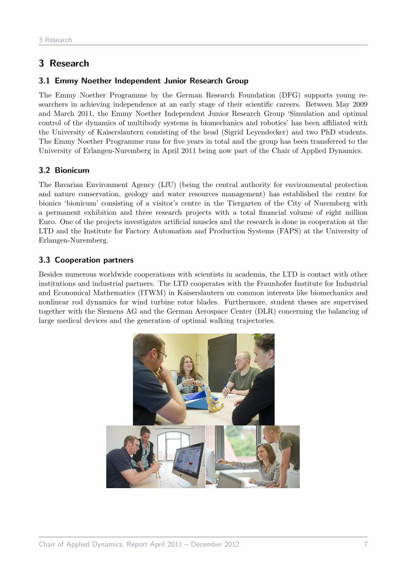
3.3 Cooperation partners
Besides numerous worldwide cooperations with scientists in academia, the LTD is contact with otherinstitutions and industrial partners. The LTD cooperates with the Fraunhofer Institute for Industrialand Economical Mathematics (ITWM) in Kaiserslautern on common interests like biomechanics andnonlinear rod dynamics for wind turbine rotor blades. Furthermore, student theses are supervisedtogether with the Siemens AG and the German Aerospace Center (DLR) concerning the balancing oflarge medical devices and the generation of optimal walking trajectories.
Chair of Applied Dynamics, Report April 2011 – December 2012 7

3 Research
3.4 Scientific reports
The following pages present a short overview on the various ongoing research projects pursued atthe Chair of Applied Dynamics. These are partly financed by third-party funding (German ResearchFoundation DFG) and in addition by the core support of the university.
Research topics
Numerical experiments for viscoelastic Cosserat rods with Kelvin-Voigt dampingHolger Lang, Sigrid Leyendecker, Joachim Linn
Phase lag analysis of variational integrators using interpolation techniquesOdysseas T. Kosmas, Sigrid Leyendecker
Computing time investigations of variational multirate systemsTobias Gail, Sigrid Leyendecker
Optimal control of monopedal jumpingMichael W. Koch, Sigrid Leyendecker
Asynchronous variational Lie group integration for geometrically exact beam dynamicsFrancois M.A. Demoures, Francois Gay-Balmaz, Thomas Leitz, Sigrid Leyendecker,Sina Ober-Blobaum, Tudor S. Ratiu
Muscle paths in biomechanical multibody simulationsRamona Maas, Sigrid Leyendecker
A numerical approach to multiobjective optimal control of multibody dynamicsMaik Ringkamp, Sigrid Leyendecker, Sina Ober-Blobaum
Numerical experiments for viscoelastic Cosserat rods with Kelvin-Voigt damping
Holger Lang, Sigrid Leyendecker, Joachim Linn
Although having been known in rational mechanics for several decades, geometrically exact rod modelsof Cosserat type [1] still provide an interesting topic of research in computational mechanics [2].Likewise, Cosserat rods provide a useful aproach to model slender flexible structures in multibodysystem dynamics simulations [3]. The basic kinematics of a Cosserat rod is depicted in Figure 1.In realistic applications, simulation models for computing the transient response of structural membersto dynamic excitations have to account for dissipative effects. In particular, in the case of geometri-cally exact rods, any approach to model viscous damping requires the inclusion of a frame-indifferentviscoelastic constitutive model already on the level of the continuum formulation of the structuralmodel, such that large displacements and finite rotations can be handled properly.In our recent work [4], we introduce viscous material damping in our quaternionic reformulation ofSimo’s rod model [1]. We formulate a Kelvin-Voigt type constitutive model
F = CF · (V −V0) + VF · ∂tV , M = CM · (U−U0) + VM · ∂tU (1)
Chair of Applied Dynamics, Report April 2011 – December 2012 8

3 Research
Figure 1: Left: Kinematic quantities for the (deformed) current and (undeformed) reference configu-rations of a Cosserat rod. Right: Snapshots of a purely torsional, slightly damped vibrationof a cosserat rod, fully clamped at the lower end.
by adding viscous contributions to the material stress resultants F(s, t) and stress couples M(s, t).These are assumed to be proportional to the rates ∂tU and ∂tV of the material strain measures U(s, t)and V(s, t) of the rod. In the material constitutive equations (1), the elastic properties of the rod aredetermined by the effective stiffness parameters contained in the symmetric 3 × 3 matrices CF andCM . For homogeneous isotropic materials, both are diagonal and given by
CF = diag (GAκ1, GAκ2, EA) , CM = diag (EI1, EI2, GJT ) (2)
with stiffness parameters in terms of the elastic moduli E and G and geometric parameters of thecross section (area A, geometric area moments I1 and I2, torsional area moment JT = (I1 + I2)κ3,including modifications by shear correction factors κi, i = 1, 2, 3, accounting for out-of-plane crosssection warping) .In our recent contribution [5], we present a derivation of the Kelvin-Voigt model (1) from three-dimensional continuum theory. In addition to the effective stiffness parameters (2), we derive explicitformulas for the damping parameters of the model given by the diagonal elements of the effectiveviscosity matrices
VF = CF · diag (τS , τS , τE) , VM = CM · diag (τE , τE, τS) (3)
in terms of the elastic stiffness parameters of the rod and the retardation time constants τS = ηS/Gand τE = ηE/E, including the shear and extensional viscosity ηS and ηE , respecively. These dampingparameters model the integrated cross-sectional viscous damping behaviour associated to the basicdeformation modes (bending, twisting, transverse shearing and extension) of the rod, in the same wayas the well known stiffness parameters given above model the corresponding elastic response.Although the Kelvin-Voigt model with damping parameters as given by (3) is already in use in practicalapplications [6], provided that reasonable guesses for the choice of the time constants τS and τE areavailable, a systematic investigation of the Kelvin-Voigt model has not yet been done for generaltypes of motion and deformation. In this work, we intend to present the results of such a systematicinvestigation obtained from a variety of numerical experiments, e.g. torsional vibrations in Figure 1with numerical results in Figure 2.
Chair of Applied Dynamics, Report April 2011 – December 2012 9

3 Research
Figure 2: Left: Dynamic evolution of selected torsional angles for purely torsional vibrations. Right:Energies for damped torsional vibrations. The discrepancy between the total energy E(t) =T (t) + V (t) and E(t = 0) +
∫ t
0 Pv(τ)dτ with the viscous power Pv estimates the numericaldamping of the underlying numerical time integration scheme.
References
[1] J.C. Simo. A finite strain beam formulation: the three dimensional dynamic problem – Part I.Comp. Meth. Appl. Mech. Engrg., Vol. 49, pp. 55-70, 1985.
[2] P. Jung, S. Leyendecker, J. Linn and M. Ortiz. A discrete mechanics approach to the Cosseratrod theory – Part I: static equilibria. Int. J. Numer. Meth. Engng., Vol. 85(1), pp. 31-60, 2011.
[3] S. Leyendecker, P. Betsch and P. Steinmann. The discrete null space method for the energy consis-tent integration of constrained mechanical systems. Part III: Flexible multibody dynamics. Multi-body System Dynamics, Vol. 19(3), pp. 45-72, 2008.
[4] H. Lang, J. Linn and M. Arnold. Multibody dynamics simulation of geometrically exact CosseratRods. Multibody System Dynamics, Vol. 25(3), pp. 285-312, 2011.
[5] J. Linn, H. Lang and A. Tuganov.Geometrically exact Cosserat rods with Kelvin-Voigt type viscousdamping. In P. Eberhard and P. Ziegler, editors, Proceedings of the Second Joint InternationalConference on Multibody System Dynamics, IMSD, Stuttgart, Germany, ISBN 978-3-927618-32-9, 2012.
[6] M. Schulze, S. Dietz, A. Tuganov, H. Lang and J. Linn. Integration of nonlinear models offlexible body deformation in Multibody System Dynamics. In P. Eberhard and P. Ziegler, editors,Proceedings of the Second Joint International Conference on Multibody System Dynamics, IMSD,Stuttgart, Germany, ISBN 978-3-927618-32-9, 2012.
Chair of Applied Dynamics, Report April 2011 – December 2012 10

3 Research
Phase lag analysis of variational integrators using interpolation techniques
Odysseas T. Kosmas, Sigrid Leyendecker
In the general framework of geometric numerical integration, variational integration are very popu-lar, due to their symplectic and momentum conservation properties and their good energy behavior[1]. Following the steps of the derivation of Euler-Lagrange equations in the continuous Lagrangiandynamics, one can derive the discrete time Euler-Lagrange equations. For this purpose, one considersapproximate configurations q0 ≈ q(0) and q1 ≈ q(h) and a time step h ∈ R, in order to replace theparameters of position q and velocity q in the continuous time Lagrangian L : TQ → R being definedon the tangent bundle to the configuration manifold Q. In the discrete setting, a discrete LagrangianLd : Q × Q → R is defined to approximate the action integral along the curve segment between qkand qk+1, i.e. Ld(qk, qk+1) ≈
∫ tk+1
tkL(q, q)dt. This leads to an action sum Sd(γd) =
∑N−1k=1 Ld(qk, qk+1)
with γd = (q0, . . . , qN ) representing the discrete trajectory. The discrete Hamilton’s principle statesthat a motion γd of the discrete mechanical system extremizes the action sum, i.e. δSd = 0. Bydifferentiation and rearrangement of the terms and having in mind that both q0 and qN are fixed, thediscrete Euler-Lagrange equations (DEL) are obtained [1, 4]
D2Ld(qk−1, qk) +D1Ld(qk, qk+1) = 0, k = 1, ..., N − 1
where the notation DiLd indicates the slot derivative with respect to the i-th argument of Ld.
The features of the phase fitting technique may be observed in its application to first order ordinarydifferential equations, as e.g. to the test problem dy(t)
dt= iωy(t), y(0) = 1 which has the exact solution
of oscillatory type y(t) = eiωt. A numerical map Φ(h), when applied to a set of known past values,produces a numerical estimation y(t + h). By calculating the ratio of the estimated solution to the
exact one y(t+h)y(t+h) = α(ωh)e−iℓ(ωh), one obtains the phase lag ℓ(ωh) of the numerical map Φ(h). The
general goal of the phase fitting technique is to minimize the phase lag while simultaneously forcingα(ωh) to be as closely as possible to unity, see [3].
To construct high order methods, we approximate the action integral along the curve segment betweenqk and qk+1, using a discrete Lagrangian that depends only on the end points. We can obtain expres-sions for configurations qj and velocities qj for j = 0, ..., S, S ∈ N at time tj ∈ [tk, tk+1] by expressingtj = tk + Cjh for Cj ∈ [0, 1] such that C0 = 0, CS = 1 for h = tk+1 − tk using
q(tj) = g1(tj)qk + g2(t
j)qk+1, q(tj) = g1(tj)qk + g2(t
j)qk+1 (1)
The functions g1(tj) and g2(t
j) are chosen for the intended type of the interpolation, see Table 1. Forcontinuity, g1(tk+1) = g2(tk) = 0 and g1(tk) = g2(tk+1) = 1 is required.
interpolation g1(tj) g2(t
j)
linear 1− tj−tkh
tj−tkh
cubic 1− tj−tkh
− 16
[
(
1− tj−tkh
)3−
(
1− tj−tkh
)
]
h2ω2 tj−tkh
− 16
[
(
tj−tkh
)3− tj−tk
h
]
h2ω2
trigonometricsin
(
u−tj−tk
hu
)
sinu
sin
(
tj−tkh
u
)
sinu
Table 1: Functions g1(tj) and g2(t
j) of (1) using linear interpolation, cubic spline interpolation andinterpolation via trigonometric functions.
Chair of Applied Dynamics, Report April 2011 – December 2012 11

3 Research
For any choice of interpolation we can now define the discrete Lagrangian by the weighted sum
Ld(qk, qk+1) = h
S∑
j=0
wjL(q(tk + Cjh), q(tk + Cjh)),
where it can be easily proved that for maximal algebraic order∑S
j=0wj(Cj)m = 1
m+1 , where m =0, 1, . . . must hold, see [2].It can be shown that for the case of variational integrators using trigonometric functions g1(t
j) andg2(t
j), the phase lag is zero for u = ωh. For the numerical solution of orbital problems, the estimationof the parameter ω can be obtained by calculating the angular velocity
ω(t) =|q(t)× q(t)|
|q(t)|2(2)
for the generalized configuration q(t) of particles motion.
phase lag ℓ(ωh)
frequency S linear cubic trigonometric
ω = 1 3 −8.33294e − 12 −2.42861e − 17 0ω = 10 5 −8.29447e − 07 −2.77840e − 10 0ω = 50 8 −2.30817e − 03 −1.45884e − 06 0
Table 2: Phase lag for integrators using different interpolation techniques for the numerical simulationof the harmonic oscillator with different frequencies ω using h = 0.01. For the trigonometriccase u = ωh has been used, with ω taken from (2).
0 10 20 30 40 50 60 70 80 90 100−0.8
−0.75
−0.7
−0.65
−0.6
−0.55
−0.5
−0.45
Time
Tota
l ene
rgy
Trigode45ode113ode23
0 10 20 30 40 50 60 70 80 90 100−0.9
−0.8
−0.7
−0.6
−0.5
−0.4
Time
To
tal e
ne
rgy
Trigode45ode113ode23
Figure 1: Total energy evolution for the two body problem using trigonometric interpolation withS = 5 and h = 0.01 compared with ode45, ode113 and ode23. Left: eccentricity ǫ = 0.2.Right: eccentricity ǫ = 0.8.
We first consider the simple harmonic oscillator, see [5], with frequency ω. In Table 2, the calculatedphase lag ℓ(ωh) for integrators using linear, cubic and trigonometric interpolation is shown for differentfrequencies ω using h = 0.01. Moreover, methods with different numbers of intermediate points Shave been used, i.e. more intermediate points are used for cases of high frequencies in order to keepthe resulting ℓ(ωh) rather small when using linear and cubic interpolation.For the case of the planar two body problem in Fig. 1, see [5], the total energy behavior of the proposedtrigonometric method is illustrated by plotting the energy evolution for small and high eccentricities,ǫ = 0.2 and ǫ = 0.8, respectively. The results have been compared to standard ode solvers, i.e. ode45,ode113 and ode23 and one can see that the total energy of the proposed technique is stable for longterm integration for any chosen eccentricities.
Chair of Applied Dynamics, Report April 2011 – December 2012 12

3 Research
References
[1] J.E. Marsden, and M. West. Discrete mechanics and variational integrators. Acta Numerica,Vol. 10, pp. 357-514, 2001.
[2] O.T. Kosmas, and D.S. Vlachos, Phase-fitted discrete Lagrangian integrators. Computer PhysicsCommunications, Vol. 181, pp. 562-568, 2010.
[3] L. Brusca, and L. Nigro, A one-step method for direct integration of structural dynamic equations.Int. J. Numer. Methods Engng., Vol. 15, pp. 685-699, 1980.
[4] M. Leok, and J. Zhang, Discrete Hamiltonian Variational Integrators. IMA Journal of NumericalAnalysis, Vol. 31, pp. 1497-1532, 2011.
[5] E. Hairer, C. Lubich, and G. Wanner, Geometric numerical integration illustrated by the Stormer-Verlet method. Acta Numerica, Vol. 12, pp. 399-450, 2003.
Computing time investigations of variational multirate systems
Tobias Gail, Sigrid Leyendecker
We investigate the behavior of the computing time of variational mutlirate integration. For mechanicalsystems with dynamics on varying time scales, the numerical integration has to comply with contra-dicting requirements. On the one hand, to guarantee a stable integration of the fast motion, we needtiny step sizes. On the other hand, for the slow motions, a larger time step size is accurate enough.Furthermore, too small time steps increase the computing time unnecessarily, especially for costlyfunction evaluations. For this, multirate systems split the system into subsystems [1] which can besolved with different methods [2]. For the multirate scheme we use two time step sizes in the frame-work described as variational multirate integration [3]. With this approach, we expect less computingtime and demonstrate that this is the case by means of numerical examples. The example systemsare the Fermi-Pasta-Ulam Problem (FPU), a triple spherical pendulum and a simple atomistic model,all consisting of multiple masspoints and springs while the latter two contain rigid links described byholonmic constraints.Let a mechanical system be described by a Lagrangian with a configuration vector q(t) ∈ Q ⊆ R
n anda velocity vector q ∈ TQ ⊆ R
n. Also, let the mechanical system be constrained by the mc dimensionalholonomic function of constraints requiring g(q) = 0. Now, let the mechanical system contain fastand slow dynamics. Let this be characterized by the possibility to split the variables into ns slow andnf fast variables with q = (qs, qf ) and n = ns + nf . Furthermore, we assume that we can split thepotential energy into a slow potential V (q) and a fast potential W (qf ). Via Hamilton’s principal theconstrained multirate Euler-Lagrange equations can be derived.
d
dt
∂T
∂qs−
∂V
∂qs−
(
∂g
∂qs
)T
· λ = 0
d
dt
∂T
∂qf−
∂V
∂qf−
∂W
∂qf−
(
∂g
∂qf
)T
· λ = 0 (1)
g(q) = 0
Here T denotes the kinetic energy and λ the Lagrangian multiplier.To approximate the solution, rather than choosing one time grid we choose two time grids. Here themacro time step is ∆T , the micro time step is ∆t and ∆T ≥ ∆t holds.
Chair of Applied Dynamics, Report April 2011 – December 2012 13

3 Research
Figure 1: Example without constraints: the Fermi-Pasta-Ulam Problem with slow and fast variables.
Figure 2: Macro and micro time grid.
The macro time grid provides the domain for the discrete slow variables qsd = {qsk}Nk=0 with qsk ≈ qs(tk),
while the micro time grid provides the domain for the discrete fast variables qfd = {{qf,mk }pm=0}N−1k=0
with qf,mk ≈ qf (tmk ) and the discrete Lagrangian multipliers λd = {{λmk }pm=0}
N−1k=0 with λm
k ≈ λ(tmk ).With Ld the discrete Lagrangian and hd the product of discrete constraints and multipliers, we get thediscrete action Sd approximating the continuous action. Via a discrete form of Hamilton’s principalrequiring stationarity for the discrete action δSd = 0, we derive the discrete constrained multirateEuler-Lagrange equations.To solve this system, a residual Newton-Raphson method with an analytical Jacobian is used. There-for, we need to derive the discrete multirate Euler-Lagrange equations with respect to all unknowns.For a constrained system the structure of the (ns + pnf +mcs + pmcsf ) × (ns + pnf +mcs + pmcsf )Jacobian block matrix is:
Dqsk+1
(Dqsk(Ld + hd)) D
qf,1,...,pk
(Dqsk(Ld + hd)) Dλk
(Dqsk(hd))
Dqsk+1
(Dqf,0,...,p−1
k
(Ld + hd)) Dqf,1,...,pk
(Dqf,0,...,p−1
k
(Ld + hd)) Dλk(D
qf,0...,p−1
k
(hd))
Dqsk+1
(Dλk(hd)) D
qf,1,...,pk
(Dλk(hd)) 0
(2)
with p the number of micro steps per macro step and with mc the number of constraints split intomcs constraints depending only on slow variables and mcsf constraints depending on slow and fastvariables with mc = mcs +mcsf .Quadrature rules are needed to approximate the action and constraints by discrete quantities. Weuse e.g. the midpoint rule, the trapezoidal rule the affine combination and finite difference. Differentquadrature rules can be chosen for the kinetic energy, both potential energies and the constraints,which gives us a wide range of possible combinations. The choice of quadrature rule has an influenceon the structure of the Jacobian and leads to ”fully implicit”, ”explicit slow, implicit fast” and ”fullyexplicit” schemes.Since we want to demonstrate that the computing time is lower for an increasing number of microsteps per macro step, we leave the accuracy constant, i.e. a constant micro time step size ∆t = constis used. This leads to a larger macro time step size with ∆T = p∆t. For different numbers of microsteps, within the range 1 ≤ p ≤ 1000, we measure the computing times. The computing times arecompared for all quadrature rules for all three examples. Figure 4 shows an exemplary plot for thecomputing times for 1 ≤ p ≤ 100 for one example system, the Fermi-Pasta-Ulam Problem, and thedifferent quadrature rules.
Chair of Applied Dynamics, Report April 2011 – December 2012 14
3 Research
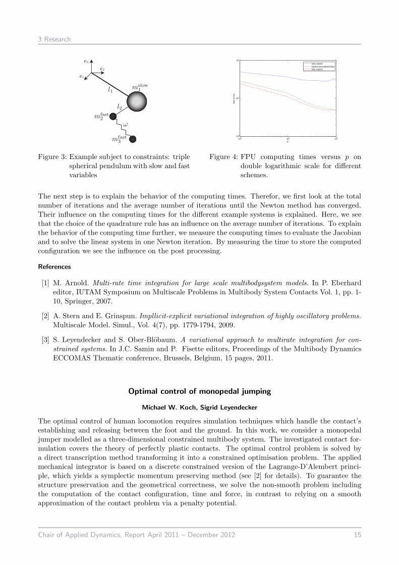
Figure 3: Example subject to constraints: triplespherical pendulum with slow and fastvariables
100 101 102100
101
102
p
time
in s
ec
fully implicitexplicit slow,implicit fastfully explicit
Figure 4: FPU computing times versus p ondouble logarithmic scale for differentschemes.
The next step is to explain the behavior of the computing times. Therefor, we first look at the totalnumber of iterations and the average number of iterations until the Newton method has converged.Their influence on the computing times for the different example systems is explained. Here, we seethat the choice of the quadrature rule has an influence on the average number of iterations. To explainthe behavior of the computing time further, we measure the computing times to evaluate the Jacobianand to solve the linear system in one Newton iteration. By measuring the time to store the computedconfiguration we see the influence on the post processing.
References
[1] M. Arnold. Multi-rate time integration for large scale multibodysystem models. In P. Eberhardeditor, IUTAM Symposium on Multiscale Problems in Multibody System Contacts Vol. 1, pp. 1-10, Springer, 2007.
[2] A. Stern and E. Grinspun. Impllicit-explicit variational integration of highly oscillatory problems.Multiscale Model. Simul., Vol. 4(7), pp. 1779-1794, 2009.
[3] S. Leyendecker and S. Ober-Blobaum. A variational approach to multirate integration for con-strained systems. In J.C. Samin and P. Fisette editors, Proceedings of the Multibody DynamicsECCOMAS Thematic conference, Brussels, Belgium, 15 pages, 2011.
Optimal control of monopedal jumping
Michael W. Koch, Sigrid Leyendecker
The optimal control of human locomotion requires simulation techniques which handle the contact’sestablishing and releasing between the foot and the ground. In this work, we consider a monopedaljumper modelled as a three-dimensional constrained multibody system. The investigated contact for-mulation covers the theory of perfectly plastic contacts. The optimal control problem is solved bya direct transcription method transforming it into a constrained optimisation problem. The appliedmechanical integrator is based on a discrete constrained version of the Lagrange-D’Alembert princi-ple, which yields a symplectic momentum preserving method (see [2] for details). To guarantee thestructure preservation and the geometrical correctness, we solve the non-smooth problem includingthe computation of the contact configuration, time and force, in contrast to relying on a smoothapproximation of the contact problem via a penalty potential.
Chair of Applied Dynamics, Report April 2011 – December 2012 15
3 Research
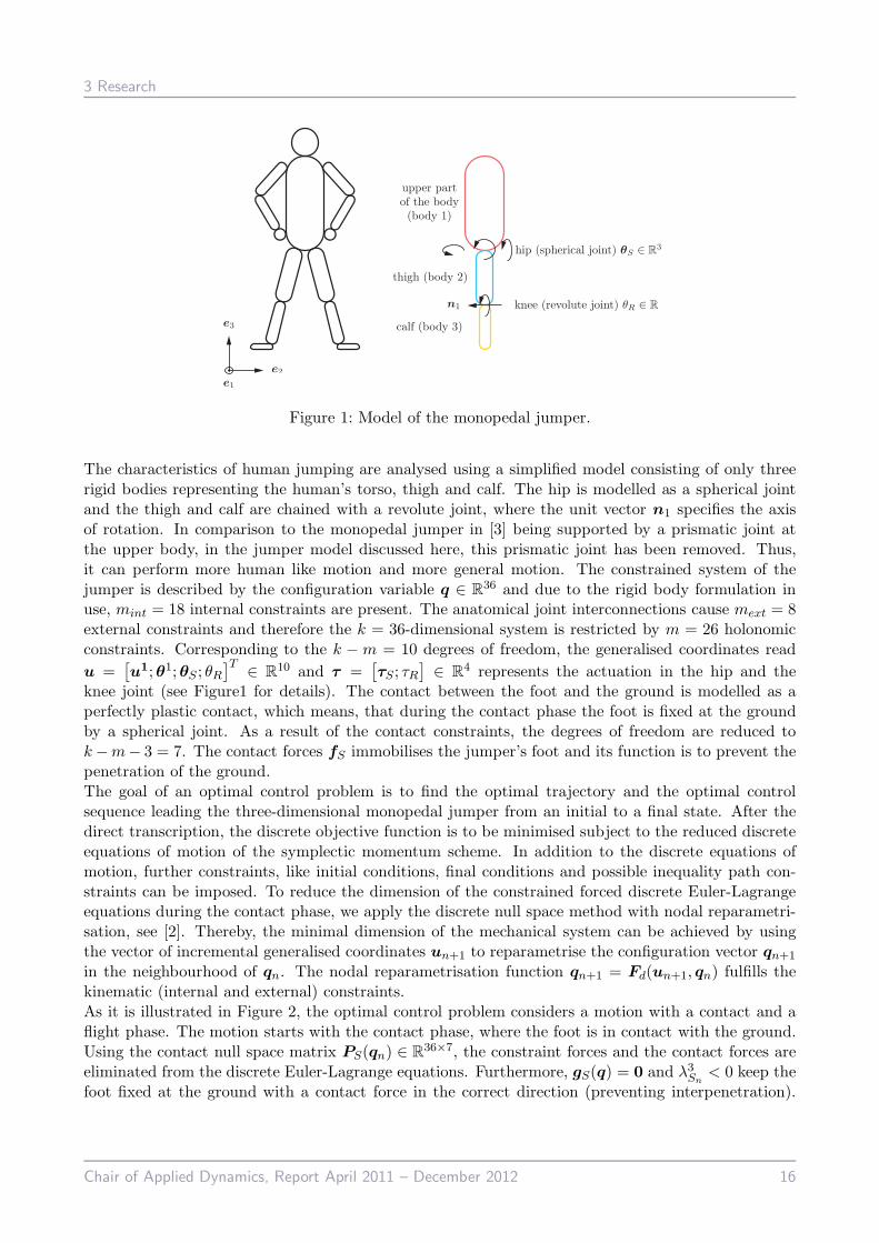
Figure 1: Model of the monopedal jumper.
The characteristics of human jumping are analysed using a simplified model consisting of only threerigid bodies representing the human’s torso, thigh and calf. The hip is modelled as a spherical jointand the thigh and calf are chained with a revolute joint, where the unit vector n1 specifies the axisof rotation. In comparison to the monopedal jumper in [3] being supported by a prismatic joint atthe upper body, in the jumper model discussed here, this prismatic joint has been removed. Thus,it can perform more human like motion and more general motion. The constrained system of thejumper is described by the configuration variable q ∈ R
36 and due to the rigid body formulation inuse, mint = 18 internal constraints are present. The anatomical joint interconnections cause mext = 8external constraints and therefore the k = 36-dimensional system is restricted by m = 26 holonomicconstraints. Corresponding to the k − m = 10 degrees of freedom, the generalised coordinates read
u =[
u1;θ1;θS ; θR]T
∈ R10 and τ =
[
τS ; τR]
∈ R4 represents the actuation in the hip and the
knee joint (see Figure1 for details). The contact between the foot and the ground is modelled as aperfectly plastic contact, which means, that during the contact phase the foot is fixed at the groundby a spherical joint. As a result of the contact constraints, the degrees of freedom are reduced tok−m− 3 = 7. The contact forces fS immobilises the jumper’s foot and its function is to prevent thepenetration of the ground.The goal of an optimal control problem is to find the optimal trajectory and the optimal controlsequence leading the three-dimensional monopedal jumper from an initial to a final state. After thedirect transcription, the discrete objective function is to be minimised subject to the reduced discreteequations of motion of the symplectic momentum scheme. In addition to the discrete equations ofmotion, further constraints, like initial conditions, final conditions and possible inequality path con-straints can be imposed. To reduce the dimension of the constrained forced discrete Euler-Lagrangeequations during the contact phase, we apply the discrete null space method with nodal reparametri-sation, see [2]. Thereby, the minimal dimension of the mechanical system can be achieved by usingthe vector of incremental generalised coordinates un+1 to reparametrise the configuration vector qn+1
in the neighbourhood of qn. The nodal reparametrisation function qn+1 = Fd(un+1, qn) fulfills thekinematic (internal and external) constraints.As it is illustrated in Figure 2, the optimal control problem considers a motion with a contact and aflight phase. The motion starts with the contact phase, where the foot is in contact with the ground.Using the contact null space matrix PS(qn) ∈ R
36×7, the constraint forces and the contact forces areeliminated from the discrete Euler-Lagrange equations. Furthermore, gS(q) = 0 and λ3
Sn< 0 keep the
foot fixed at the ground with a contact force in the correct direction (preventing interpenetration).
Chair of Applied Dynamics, Report April 2011 – December 2012 16

3 Research
Figure 2: Time grid and dynamical constraints of the jumper’s optimal control problem.
When the vertical component of the contact force vanishes (λ3Sn
= 0), the jumper’s foot contact tothe ground is released and the flight phase starts, where the foot stays above the ground (gc(qn) > 0).
Figure 3: Snapshots of an optimised motion at the beginning, the contact release and at the end ofthe motion.
The constrained optimisation problem is formulated in terms of the discrete generalised coordinatesud and the discrete actuation torques τd. The actuation of the monopedal jumper during the contactphase has an essential effect on the time of contact release and on the height and width of the jump.The optimal contact release time tNκ is not known, therefore the note number Nκ is predefined andthe time steps before and after the contact release are scaled by the parameters σ1, σ2 ∈ R. Thescaling factors are part of the optimization variables. At the beginning of the manoeuvre, equalityconditions guarantee an initial state q0(t0) = q0, p(t0) = p0 of the jumper, whereby p0 = 0 representsthe zero conjugate momentum at the initial configuration, thus the motion starts at rest. During theoptimal controlled motion several path constraints are present, e.g. an inequality constraint preventsthe jumper’s knee super-extension and another guarantees the correct orientation of the contact forces.
Figure 3 illustrates some configurations of an optimised motion, which starts at rest and the inequalityconstraints at the end ensure a minimum jump height of 1.5 m. The configuration at the beginning ofthe motion and the actuation forces are part of the optimisation problem. The goal is to investigate
Chair of Applied Dynamics, Report April 2011 – December 2012 17

3 Research
high and long jumps with physiologically motivated cost functions and eventually a three-segmentalfoot model is applied (details can be found in [1]).
References
[1] M. Gunther. Computersimulation zur Synthetisierung des muskular erzeugten menschlichenGehens unter Verwendung eines biomechanischen Mehrkorpermodells. PhD thesis, Eberhard-Karls-Universitat zu Tubingen, 2010.
[2] S. Leyendecker, S. Ober-Blobaum, J.E. Marsden and M. Ortiz. Discrete mechanics and optimalcontrol for constrained systems. Comput. Methods Appl. Mech. Engrg., Vol. 31, pp. 505–528, 2009.
[3] M.W. Koch and S. Leyendecker. Structure preserving simulation of monopedal jumping. Archiveof Mechanical Engineering, acccepted for publication, 2012.
Asynchronous variational Lie group integration for geometrically exact beam dynamics
Francois M.A. Demoures, Francois Gay-Balmaz, Thomas Leitz,
Sigrid Leyendecker, Sina Ober-Blobaum, Tudor S. Ratiu
The theory of discrete variational mechanics has its roots in the optimal control literature of the 1960’s.The past ten years have seen a major development of discrete variational mechanics and correspondingnumerical integrators, largely due to pioneering work by Jerrold Marsden and his collaborators, e.g.in [1]. The discrete Lagrangian Ld approximates the action in a time interval [tj−1, tj]. For linearvector spaces, i.e. q ∈ R
n, this leads to the discrete action sum
Sd =∑
N
Ld (qj−1, qj)
and the discrete variational principle δSd = 0 results in the discrete Euler-Lagrange equations
D2Ld (qj−1, qj) +D1Ld (qj, qj+1) = 0 (1)
which due to the variational derivation are symplectic and conserve discrete momentum maps [1].Asynchronous variational integrators (AVI), as described by Lew et. al. [2], offer the possibility touse different time steps for every element of the spatial discretization. The use of AVI promises lesscomputational costs by increasing the time step sizes for slowly moving parts of the beam.We review the kinematic description of the geometrically exact beam model in the ambient spaceR3 presented in [3]. The configuration of a beam is defined by specifying the position of its line of
centroids by means of a map φ : [0, L] → R3, and the orientation of cross-sections at points φ(S) by
means of a moving basis {d1(S),d2(S),d3(S)} attached to the cross section. The orientation of themoving basis is described with the help of an orthogonal transformation Λ : [0, L] → SO(3) such that
dI(S) = Λ(S)EI , I = 1, 2, 3
where {E1,E2,E3} is a fixed basis referred to as the material frame. The configuration of the beamis thus completely determined by the maps φ and Λ in the configuration space
C∞ ([0, L], SE (3))
with the Lie group SE (3) being the Euclidean group. If we take into account that the thickness ofthe rod is small compared to its length and that the material is homogenous and isotropic, we can
Chair of Applied Dynamics, Report April 2011 – December 2012 18

3 Research
consider the stored energy to be given by a quadratic model. The discretization of the beam [0, L] inN elements K ∈ T (with two nodes in each K) and T being the set of all elements, is done in a waythat provides objective strain measures [4].The mechanical system evolves on a Lie group. As a consequence, we use the discrete LagrangianLjK : G × G → R, which can be defined by considering the contribution of the K-th element to the
discrete reduced Lagrangian over the time interval [tjK , tj+1K ]. Similar to the derivation of the discrete
Euler-Lagrange equations on Lie groups developed by Bobenko, Suris [5] and Lee [6, 7], the discreteaction sum becomes
Sd((Λd, xd)) =∑
K∈T
∑
1≤j<N
LjK
with (Λd, xd) being the discrete curve in SE (3). In contrast to equation (1) for the linear vectorspace, applying the discrete Hamilton’s principle to the discrete action sum leads to the discreteEuler-Lagrange equations for a node a
T ∗e L(F j−1
a ,Hj−1a )
(
DF
j−1a
Lj−1a , D
Hj−1a
Lj−1a
)
−Ad∗(F j
a ,Hja)−1
T ∗e L(F j
a ,Hja)
(
DF
jaLja, D
HjaLja
)
+ T ∗e L(Λj
a,xja)
(
DΛjaLja, D
xjaLja
)
= 0,
for all a ∈ N with N being the set of all nodes. Left multiplication by g ∈ SE (3) is dentoed byLg (f) = gf and T ∗Lg (f) is the contangent lifted action. For a node a, the discrete configuration gj
and the temporal configuration increment f j =(
gj)−1
gj+1 associated to this node are
gj = (Λja, x
ja) and f j = (F j
a ,Hja) := (Λj
a, xja)
T (Λj+1a , xj+1
a ) =(
(Λja)
TΛj+1a , (Λj
a)T (xj+1
a − xja))
.
0
1
2
x1x2
x3
t = 0s
0
1
2
x1x2
x3
t = 0.05s
0
1
2
x1x2
x3
t = 0.1s
0 0.2 0.4 0.6 0.8 10
2
4
6
8
t in s
Ein
J
kinetic energypotential energytotal energy
Figure 1: Simulation of a geometrically exact beam with momentum initial conditions using AVI. Left:Snapshots of the motion. Right: Corresponding energy plot with no numerical dissipation.
The asynchronous Lie group variational integrator is implemented in Matlab using a priority queuedescribed by [2] modified to allow time coincidences of two adjecent elements. This modification leadsto a universal integrator, that allows synchronous as well as asynchronous time stepping. Figure 1shows snapshots of the motion of a beam with nonzero initial conditions on momentum level and aprescribed deformed initial configuration. The corresponding energy plot shows that the presentedintegrator exhibits no numerical dissipation.
Chair of Applied Dynamics, Report April 2011 – December 2012 19

3 Research
References
[1] J.E. Marsden and M. West. Discrete mechanics and variational integrators. Acta Numerica,Vol. 10 pp. 357-514, 2001.
[2] A. Lew, J.E. Marsden, M. Ortiz, and M. West. Asynchronous variational integrators. Arch. Ra-tional Mech. Anal., Vol. 167(2), pp. 85-146, April 2003.
[3] J.C. Simo, J.E. Marsden, and P.S. Krishnaprasad. The Hamiltonian structure of nonlinear elas-ticity: The material and convective representations of solids, rods, and plates. Arch. RationalMech. Anal., Vol. 104, pp. 125-183, 1987.
[4] M.A. Crisfield and G. Jelenic. Objectivity of strain measures in the geometrically exact three-dimensional beam theory and its finite-element implementation. Proc. Roy. Soc. London A:Mathematical, Physical and Engineering Sciences, Vol. 455(1983), pp. 1125-1147, March 1999.
[5] A.I. Bobenko and Y.B. Suris. Discrete time Lagrangian mechanics on Lie groups, with an ap-plication to the Lagrange top. Communications in Mathematical Physics, Vol. 204, pp. 147-188,1999.
[6] T. Lee. Computational geometric mechanics and control of rigid bodies. PhD thesis, Universityof Michigan, 2008.
[7] T. Lee, M. Leok, and N.H. McClamroch. Lie group variational integrators for the full body prob-lem. Comput. Methods Appl. Mech. Engrg., Vol. 196(29-30), pp. 2907-2924, May 2007.
Muscle paths in biomechanical multibody simulations
Ramona Maas, Sigrid Leyendecker
When simulating biomechanical motion with multibody systems representing bones and joints, theactuation of those systems can be implemented via Hill-type muscle models. The essential task ofthese models is to represent the typical force-length and force-velocity relation of real muscles. TheHill-model used in this work consists of a contractile component (CC) and a parallel linear elasticcomponent (PEC), see Figure 1. The scalar force amount of the muscle force FM
n in a time interval[tn, tn+1] can be calculated via
FMn = (fl)n · (fv)n · An · Fmax + kp · (lM )n (1)
assuming the parallel elasticity of the muscle to be proportional to the length of the muscle elementlM with the proportionality constant kp. Herein, fl(lM ) ∈ [0, 1] is a factor related to the force lengthrelation of the muscle, fv(vM ) ∈ [0, 1.4] represents the Hill-hyperbola like force-velocity relation,This means, to calculate the actual muscle force, we need the actual muscle length in every time stepas well as the force directions at the insertion points of the muscle. The muscle length and forcedirection is particularly related to the joint angle. Several studies use an alterable number of artificial’via’ points or ’wrapping’ points to relate the muscle path to the joint angle, see for example [3].The determination of such artificial points requires a lot of anatomical knowledge, which is not yetavailable for all biomechanical structures and the results are quite sensitive to the location of suchpoints. In software packages like OpenSim, so-called ’muscle moment arms’ are then calculated aspartial derivatives of the muscle length around those artificial points with respect to the joint angle,see for example [5, 3].
Chair of Applied Dynamics, Report April 2011 – December 2012 20

3 Research
A ∈ [0, 1] is the activity of the muscle and Fmax
is the maximal possible muscle force. The con-traction velocity of the muscle is approximated
via vM,n =(lM )n+1 − (lM )n
hwhere the time step
length is denoted by h . The muscle force τmn act-
ing on the multibody system is then given by amultiplicative set up of the scalar force value andthe force direction rn.
τmn = FM
n · rn (2)
Figure 1: Hill-type muscle model
method nodes lM r1n r
2n elapsed time
optimisation 30 0.2148[
0.6289 0.6954 −0.3478] [
0.2886 −0.9369 −0.1973]
178.5s
optimisation 15 0.2145[
0.6070 0.7123 −0.3524] [
0.2632 −0.9464 −0.1875]
16.8s
optimisation 7 0.2130[
0.5752 0.7751 −0.2617] [
0.2281 −0.9581 −0.1731]
3.1s
semi-analytical – 0.2146[
0.6192 0.6800 −0.3326] [
0.2995 −0.9343 −0.1935]
1.7s
Table 1: Comparison of optimal muscle path using optimisation with different number of nodes andthe semi-analytical path procedure combining lines, helices and orthodromes.
Our approach is to assume that the muscles and tendons are always under tension as it is describedfor example in [6], which means that tendons and muscles are supposed to follow the path of minimaldistance between two insertion points. One possibility to find this path is to minimise the length ofa tendon/muscle path between two insertion points over a joint, so that the path does not intersectthe bodies Kj . Let the path of a muscolotendon complex be discretised with ne + 1 elements withthe element length lei . We get ne nodes Ei ∈ R
3 between the insertion points p1 ∈ R3 and p2 ∈ R
3,which are summarised in the optimisation variable E = [E1,E2, . . . ,Ene ] ∈ R
3ne . The constrainedoptimisation problem reads
minE
lM =minE
‖p1 −E1‖+ ‖Ene − p2‖+ne−1∑
i=1
‖Ei −Ei+1‖
so that: ·Ei /∈ Kj
·lemin< lei < lemax for i = 1, . . . , ne + 1
(3)
Solving this problem yields a linear approximation of the length of the muscle path. The force di-rection at the insertion points is given via the normalised direction of the first and the last element.However, using an optimisation procedure like this during forward dynamics or optimal control simu-lations leads to several problems. First of all, the computation is very expensive, as for every musclein every time step such an optimisation procedure has to be executed. Secondly, analytical gradientsfor optimal control simulations are difficult to calculate, since the muscle length is the solution of aparameter dependent optimisation.Within our multibody simulation framework for biomechanical systems, we represent bones and jointsvia mostly smooth bodies like cylinders and spheres. It is known that the shortest path on the sur-face of a cylinder is a helix and the shortest path on a sphere is an orthodrome. We want to reducecomputational effort in finding the path of minimal length around bodies and joints with an algo-rithm that determines this path as a G1-continuous combination of straight lines (wherever possible,i.e. whenever the straight line does not intersect the bodies or joints), helices and orthodromes. Notethat G1 (geometrical) continuously joined curves share tangential directions, while the length of thetangent vectors might differ. Thus, the length of this path can directly be calculated as the sum ofthe length of the single parts and the force direction is given via the tangent vector at the insertion
Chair of Applied Dynamics, Report April 2011 – December 2012 21

3 Research
points. From Table 1 it is obvious, that the simulation time can be significantly reduced by using thissemi-analytical algorithm, whereas force direction and path length are comparable to those calculatedwith optimisations. In the left part of Figure 1, the muscle path resulting from an optimisation pro-cedure with 30 nodes is depicted whereas the right part shows the semi-analytical solution, which isin this case a G1-continuous helix-line-helix combination.Finally, when knowing the muscle path length, the scalar force amount and the force direction, thediscrete forces can be calculated as described for example in [1]. Inserting them into the reduced dis-
Figure 2: Example of a muscle path. Left: solution of a 30 node optimisation. Right: the semi-analytical solution.
crete version of the constrained Lagrange-d’Alembert principle, see for example [2, 1, 4], the resultingscheme can be solved either during forward dynamics simulations or it serves as constraints in optimalcontrol simulations. Using the variational integrator resulting from the discrete Lagrange-d’Alembertprinciple instead of simply discretising the continuous equations of motion yields a structure preserv-ing simulation. This means that the angular momentum is changing only and exactly according to theapplied forces and the results show a good energy behaviour. The next step of this work is to imple-ment this algorithm in forward dynamics and optimal control simulations of biomechanical systemslike the human arm, finger and hand.
References
[1] S. Leyendecker, S. Ober-Blobaum, J.E. Marsden and M. Ortiz. Discrete mechanics and optimalcontrol for constrained systems. Optimal Control Applications & Methods Vol. 31(6), pp. 505-528,2010.
[2] J.E. Marsden and M. West. Discrete mechanics and variational integrators. Acta Numerica,Vol. 10, pp. 357-514, 2001.
[3] W.M. Murray, L.D. Scott and T.S. Buchanan. Variation of muscle moment arms with elbow andforearm position. J. Biomechanics, Vol. 28(5), pp. 513-525, 1995.
[4] T.S. Ratiu and J.E. Marsden. Introduction to mechanics and symmetry. Springer, 2010.
[5] How to compute muscle moment arm using generalized coordinates.http://wiki.simtk.org/opensim/, November 2012.
[6] A. Winkelmann, J. Kirsch, C.A. May, D. Lorke, W. Schwab, G. Herrmann and R. Funk. Taschen-lehrbuch Anatomie. Thieme, 2011.
Chair of Applied Dynamics, Report April 2011 – December 2012 22

3 Research
A numerical approach to multiobjective optimal control of multibody dynamics
Maik Ringkamp, Sigrid Leyendecker, Sina Ober-Blobaum
Recently, a couple of approaches have been developed that combine multiobjective optimization withdirect discretization methods to approximate trajectories of optimal control problems (e.g. [1]) re-sulting in restricted optimization problems of high dimension. The solution set of a multiobjectiveoptimization problem is called the Pareto set which consists of optimal compromise solutions. A com-mon way to approximate the Pareto set is to start with at least one given Pareto solution and to evolvethe Pareto set using continuation techniques. With our approach, we first approximate the feasible setof the multiobjective optimal control problem using a global root finding algorithm. Then, we chooseappropriate points which provide initial guesses for the continuation of the Pareto set. After that, thecontinuation is performed by using a reference point method [2].
Multiobjective Optimal Control for Constrained Multibody Systems We apply the approachDMOCC [3] to a constrained formulation of multibody dynamics. That is a combination of discretemechanics and optimal control (DMOC) [4] and a discrete null space method [5]. We consider a multi-body system consisting of rigid bodies interconnected by joints. Each joint induces external constraintsfor the n-dimensional time dependent configuration vector q(t) ∈ Q in the configuration manifold Q.Moreover, the problem is given in a constrained formulation of rigid body dynamics such that inter-nal constraints are required to fulfill the underlying kinematic assumptions. Altogether, a holonomicconstraint function g : Q → R
m restricts q to the constraint manifold C := {q ∈ Q| g(q) = 0}.Under given regularity conditions, a local reparametrization function F : U → C for an open subsetU ⊆ R
n−m exists and can be given explicitly. Consequently, the configuration vector q ∈ Q and itsvelocities q ∈ Tq(t)Q in the tangent space are given by q = F (u) and q = DF (u)u. The aim is tominimize several objectives whereas the configuration vector has to satisfy the equations of motiongiven by the constrained Lagrange-d’Alembert principle in the time interval [t0, tN ] and boundaryconditions. More detailed, an optimal control problem for constrained systems is defined as follows:
Problem 1
min(u,u,τ ,tN )∈[bl,bu]
J(u, u, τ , tN ) =
∫ tN
t0
B(u(t), u(t), τ (t)) dt (1)
s.t. P (F (u))T[
∂1L(F (u),DF (u)u)−d
dt∂2L(F (u),DF (u)u) + f(u, u, τ )
]
= 0 (2)
and boundary conditions (3)
with B : TU ⊕ T ∗U → Rk and J : TU ⊕ T ∗U× ]0,∞[→ R
k and as we consider multiobjectiveproblems, we have k > 1 instead of k = 1 objectives. Here f : TU ⊕ T ∗U → T ∗Q is the forcefield and P : TU → TC is the n × (n − m) nullspace matrix that spans the tangent space of theconstraint manifold. Accordingly, P T : T ∗C → T ∗U maps the Euler-Lagrange equation (2) to theminimal dimensional space. bl and bu are lower and upper bounds on the optimization variables.Using a discretization of u and τ and finite differences for u in the variational problem transformsProblem 1 in a finite dimensional restricted optimization problem with optimization variables x =(u0, . . . ,uN , τ 0, . . . , τN−1, tN ) ∈ R
(2N+1)(n−m)+1.
Multiobjective Optimization For a given multiobjective optimization problem with objective J andfeasible set S (i.e. all points in [bl, bu] that satisfy (2) and (3)), the following definitions clarify whatis meant by the minimum:
Chair of Applied Dynamics, Report April 2011 – December 2012 23

3 Research
Definition 1 (i) A vector y ∈ S is dominated by a vector x ∈ S (in short: x ≺ y) with respect toProblem 1 if J(x) ≤ J(y) and J(x) 6= J(y).
(ii) A vector x ∈ S is called Pareto optimal or a Pareto point if there is no y ∈ S which dominatesx. Sometimes also its corresponding point in image space J(x) is called a Pareto point.
(iii) The Pareto set P is defined as the set of all Pareto points and the corresponding set in the imagespace J(P) is called the Pareto front.
Minimizing a vector valued function means to find its Pareto set. To find the Pareto set of a multiob-jective optimal control problem we propose the following solution strategy:
1. Computation of a rough approximation of the feasible set.
2. Sorting out dominated trajectories.
3. Evolution of the Pareto set using a continuation method starting from each remaining trajectory.
The first step can be done for example by using randomly chosen, possibly infeasible trajectoriesx ∈ [bl, bu] as starting points for the minimization problem minx∈S 1. This leads to a finite setof trajectories T ⊆ S. After applying a test of dominance, we sort out all dominated trajectoriesand obtain the set PT := argmin T . We use a reference point optimization for the last step. Thistechnique successively generates reference points r ∈ R
k such that no x ∈ S exists with J(x) ≤ r.Each of them is used for a distance minimization of minx∈S ‖J(x) − r‖. Thus, the vector valuedobjective J is transformed into a scalar valued auxiliary function such that standard minimizationalgorithms can be applied for the minimization.
Example: 4-Body Kinematic Chain The considered problem consists of four rigid bodies intercon-nected by two revolute joints and one spherical joint. The initial and final conditions (translation androtation) are fully specified such that the kinematic chain moves from a straight to a closed position,performing a rest to rest maneuver. The objectives to minimize are the control effort J1 for the com-plete maneuver and the required maneuver time J2. Figure 1 shows parts of the computed Paretofront and trajectories for the center of mass of each rigid body.
Figure 1: Left: Approximation of the computed Pareto front for the objectives J1 and J2. Middle:Center of mass trajectories for the Pareto point (’o’ in left). Right: Center of mass trajectoryfor the Pareto point (’+’ in left).
References
[1] S. Ober-Blobaum, M. Ringkamp, and G. zum Felde. Solving multiobjective optimal control prob-lems in space mission design using discrete mechanics and reference point techniques. In 51-thIEEE Conference on Decision and Control, Maui, HI, USA, 10-13 December 2012.
Chair of Applied Dynamics, Report April 2011 – December 2012 24

3 Research
[2] K. Miettinen. Nonlinear multiobjective optimization. Kluwer Academic Publishers, 1999.
[3] S. Leyendecker, S. Ober-Blobaum, J.E. Marsden, and M. Ortiz. Discrete mechanics and optimalcontrol for constrained systems. Optimal Control, Applications and Methods, Vol. 31(6), pp. 505-528, 2010.
[4] S. Ober-Blobaum, O. Junge, and J.E. Marsden. Discrete mechanics and optimal control: ananalysis. Control, Optimisation and Calculus of Variations, Vol. 17(2), pp. 322-352, 2011.
[5] S. Leyendecker, J.E. Marsden, and M. Ortiz. Variational integrators for constrained dynamicalsystems. Z. angew. Math. Mech., Vol. 88(9), pp. 677-708, 2008.
Chair of Applied Dynamics, Report April 2011 – December 2012 25

4 Activities
4 Activities
4.1 Teaching
Wintersemester 2012/2013
Dynamik starrer Korper (MB, ME, WING, IP, BPT, CE)Vorlesung S. Leyendecker
Ubung + Tutorium T. Gail, O.T. KosmasT. Leitz, M. Ringkamp
Mehrkorperdynamik (MB, ME, WING, TM, BPT, CE)Vorlesung S. Leyendecker
Ubung H. Lang
Theoretische Dynamik (MB, ME, WING, TM, CE, BPT)
Vorlesung + Ubung H. Lang
Numerische Methoden in der Mechanik (MB, ME, WING, TM, CE, BPT)
Vorlesung + Ubung H. Lang
Dynamik nichtlinearer Balken (MB, M, Ph, CE, ME, WING)Vorlesung H. Lang
Sommersemester 2012
Statik und Festigkeitslehre (CBI, ET, IP, LSE, ME, MT, WING, WW)Vorlesung S. Leyendecker
Ubung + Tutorium T. Leitz, O.T. Kosmasgepruft 405
Biomechanik (MT)
Vorlesung + Ubung H. Langgepruft 72
Geometrische Mechanik und geometrische Integratoren(MB, ME, CE, BPT, WING, M, TM, Ph)
Vorlesung + Ubung S. Leyendeckergepruft 3
Numerische Methoden in der Mechanik (IP, MP, ME, WING, M, TM, Ph)
Vorlesung + Ubung H. Langgepruft 17
Theoretische Dynamik II (M, TM, MB, ME, CE, BPT, WING, Ph)
Vorlesung + Ubung H. Langgepruft 0
Rechnerunterstutzte Produktentwicklung (RPE)Versuch 6: Mehrkorpersimulation in Simulink (MB, ME, WING)
Praktikum M. Koch, O.T. KosmasT. Leitz, R. Maas
Teilnehmer 70
Chair of Applied Dynamics, Report April 2011 – December 2012 26

4 Activities
Wintersemester 2011/2012
Dynamik starrer Korper (MB, ME, WING, IP, BPT, CE)Vorlesung S. Leyendecker
Ubung + Tutorium H. Lang, T. LeitzO.T. Kosmas
gepruft 591+169 (SS 2012)
Mehrkorperdynamik (MB, ME, WING, BPT, CE)Vorlesung S. Leyendecker
Ubung H. Langgepruft 13+3 (SS 2012)
Theoretische Dynamik I (M, TM, MB, ME, CE, BPT, WING, Ph)
Vorlesung + Ubung H. Langgepruft 2
Sommersemester 2011
Statik und Festigkeitslehre (CBI, ET, IP, LSE, ME, MT, WING, WW)Vorlesung S. Leyendecker
Ubung + Tutorium V. Barth, O.T. Kosmasgepruft 475
Biomechanik (MT)
Vorlesung + Ubung S. Leyendeckergepruft 31+11 (WS 11/12)
4.2 Theses
Diploma theses
• Tobias GailComputing time investigations for variational multirate schemes
• Alexander Werner (supervision with DLR)Optimization-based generation of optimal walking trajectories for biped robots
Chair of Applied Dynamics, Report April 2011 – December 2012 27

4 Activities
Master theses
• Thomas PircherBiomechanical model of the muscle tendon network in human fingers
Bachelor theses
• Johannes Rudolph (supervision with Siemens AG)Modellierung und Simulation des Unwuchtverhaltens eines CT-Systems
• Marion StadlerIndex investigations in discrete mechanics and optimal control for differential algebraic systems
4.3 Seminar for Mechanics
together with the Chair of Applied Mechanics LTM
04.04.2011 Jean-Paul PelteretCERECAM, University of Cape Town, South AfricaComputational Model of Tissue in the Human Upper Airway
05.04.2011 Louis KomzsikChief Numerical Analyst of Siemens Industry Division, PLMS in California, USAIntroduction to industrial rotor dynamics
19.04.2011 Vera LuchscheiderChair of Applied Mechanics, FAU Erlangen-Nuremberg, GermanyBruchmechanische Ermittlung der Ausfallwahrscheinlichkeit von Walzlagerbauteilen mitEinschlussen
20.06.2011 Matjaz HribersekUniversity of Maribor, SloveniaNumerical modeling of dilute suspension flows of magnetic particles by the SubdomainBoundary Element Method
28.06.2011 Holger LangITWM Kaiserslautern, GermanyGeometrisch exakte Cosseratsche Balken fur die Mehrkorpersimulation
29.06.2011 Thorsten SchindlerINRIA Grenoble, FranceNichtglatte MKS in industrieller Anwendung und theoretischer Analyse
05.07.2011 Jurgen MetzgerTRW Automotive, Alfdorf, GermanyCharacterization and Evaluation of Frontal Crash Pulses for USNCAP 2011
Chair of Applied Dynamics, Report April 2011 – December 2012 28

4 Activities
06.07.2011 Bulent YagimliUniBW Munich, GermanyExperimentelle Untersuchungen und Erstellung eines Materialmodells zur Beschreibungvon Aushartevorgangen
12.07.2011 Holger BoseISC Wurzburg, GermanySmart Materials zur gezielten Beeinflussung mechanischer Systeme
05.10.2011 Indresan GovenderUniversity of Cape Town, South AfricaFlow modeling in tumbling mills
19.01.2012 Philipp LandkammerIngenieurburo KAE GmbH, Hausen b. Forchheim, GermanyDas Antwortspektrenverfahren fur Erdbebensimulationen
26.01.2012 Fernando Jimenez AlburquerqueInstituto de Ciencias Matematicas ICMAT-CSIC, Madrid, SpainOn Discrete Mechanics for Optimal Control Theory
07.02.2012 Daniel RiedlbauerChair of Applied Mechanics, FAU Erlangen-Nuremberg, GermanyThermomechanical Modelling & Simulation of Electron Beam Melting
06.03.2012 Francesco dell’IsolaDISG, Universita di Roma “La Sapienza”, Rome, ItalyHow contact interactions may depend on the shape of Cauchy cuts in N-th gradientcontinua: approach “a la D’ Alembert”
23.03.2012 Ellen KuhlComputational Biomechanics Laboratory, Stanford University, USAComputational Optogenetics: A Novel Continuum Framework for the Photoelectro-chemistry of Living Systems
03.04.2012 Kim-Henning SauerlandLehrstuhl fur Technische Mechanik, University of Paderborn, GermanyProcess Simulation and Two Scale Tool Simulation related to Hybrid Forming
09.05.2012 Olivier VerdierDepartment of Mathematical Sciences, NTNU Trondheim, NorwegenGeometric Generalisations of the Shake and Rattle methods
21.05.2012 Oleg M. ZarechnyyDepartment of Aerospace Engineering, Iowa State University, Ames, IA, USAModeling and Simulation of Strain-Induced Phase Transformations in Rotational Dia-mond Anvil Cell
Chair of Applied Dynamics, Report April 2011 – December 2012 29

4 Activities
22.05.2012 Zoufine BareFraunhofer Institut fur Techno- und Wirtschaftsmathematik, Kaiserslautern, GermanyAsymptotic dimension reduction for linearized contact of thin fibers and simulation oftextiles based on 1D models including large deformation
05.06.2012 Barbara Rohrnbauer, Edoardo MazzaInstitute of Mechanical Systems, Swiss Federal Institute of Technology Zurich, Switzer-landMechanical characterization and modeling of prosthetic meshes at different length scales
12.06.2012 Prashant SaxenaDepartment of Mathematics, University of Glasgow, UKNonlinear magneto-elasticity: some boundary value problems
26.06.2012 Valery LevitasDepartment of Aerospace Engineering, Iowa State University, Ames, IA, USAStress- and Surface-induced Phase Transformations: Phase Field Approach
03.07.2012 Karali PatraMechanical Engineering, Indian Institute of Technology Patna, IndiaStudy on mechanical and dielectric behavior of VHB 4910 for sensors and actuatorsapplications
09.08.2012 Wencheng LiNorthwestern Polytechnic University, ChinaIntroduction of My Research Interesting on Structure Preserving Methods
06.09.2012 Kathrin FlaßkampDeparment of Mathematics, University of Paderborn, GermanyVariational Formulation and Optimal Control of Hybrid Lagrangian Systems
21.09.2012 Roger BustamanteDepartamento de Ingenieria Mecanica, Universidad de Chile, ChileImplicit constitutive relations for electro-elastic bodies
27.09.2012 Joachim LinnFraunhofer-Institut fur Techno- und Wirtschaftsmathematik, Kaiserslautern, GermanyViscoelastic Cosserat rods of KelvinVoigt and generalized Maxwell type
22.10.2012 Markus LazarHeisenberg Research Group, Continuum Mechanics, Department of Physics, DarmstadtUniversity of Technology, GermanyNon-singular Dislocations in the Theory of Gradient Elaticity
05.11.2012 Hossein TalebiInstitute of Structure Mechanics, Bauhaus-University Weimar, GermanySingle and Multi Scale Methods for Modeling Fracture and Crack Propagation: Methods,Software and Tools
Chair of Applied Dynamics, Report April 2011 – December 2012 30

4 Activities
19.11.2012 Frank FischerStructure Research Lab, Beiersdorf AG, Hamburg, GermanyThe detailed structure of human skin layers
20.11.2012 Tobias GailChair of Applied Dynamics, FAU Erlangen-Nuremberg, GermanyComputing time investigations of variational multirate schemes
22.11.2012 Axel KohlmeyerAbdus Salam International Centre for Theoretical Physics (ICTP), Trieste, Italy undInstitute for Computational Molecular Simulations (ICMS), Temple University,Philadelphia, USAAccelerating classical MD for multi-core CPUs and GPUs
04.12.2012 Maik RingkampChair of Applied Dynamics, FAU Erlangen-Nuremberg, GermanyUsing Discrete Mechanics and Reference Point Techniques to Solve Multiobjective Op-timal Control Problems in Space Mission Design and Optimal Control Multi-Body Dy-namics
05.12.2012 Johannes RudolphChair of Applied Dynamics, FAU Erlangen-Nuremberg, GermanyModellierung und Simulation des Unwuchtverhaltens eines CT-Systems
05.12.2012 Marion StadlerChair of Applied Dynamics, FAU Erlangen-Nuremberg, GermanyIndex Investigations in Discrete Mechanics and Optimal Control for Differential Alge-braic Systems
06.12.2012 Francois M.A. DemouresEPFL/ENAC/IIC/IBOIS (Laboratoire de construction en bois, Lausanne, Switzerland)Lie group and Lie algebra variational integrators for flexible beam and plate in R3
Chair of Applied Dynamics, Report April 2011 – December 2012 31

4 Activities
4.4 Press releases
Nurnberger Nachrichten, Tuesday, 6 March 2012
Chair of Applied Dynamics, Report April 2011 – December 2012 32

4 Activities
Nurnberger Nachrichten, Saturday, 20 October 2012
Chair of Applied Dynamics, Report April 2011 – December 2012 33

4 Activities
Uni Kurier Magazin, Nr. 112, September 2012
Chair of Applied Dynamics, Report April 2011 – December 2012 34

5 Publications
5 Publications
5.1 Reviewed journal publications
1. H. Lang, J. Linn, and M. Arnold. Multibody dynamics simulation of geometrically exact Cosseratrods. Multibody Dynamics, Vol. 25(3), pp. 285-312, 2011.
2. R. Maas, T. Siebert, and S. Leyendecker. On the relevance of structure preservation to simula-tions of muscle actuated movements. Biomech. Model. Mechanobiol., DOI 10.1007/s10237-011-0332-0, Vol. 11, pp. 543-556, 2012.
3. S. Leyendecker, C. Hartmann, and M.W. Koch. Variational collision integrator for polymerchains. J. Comput. Phys., DOI 10.1016/j.jcp.2012.01.017, Vol. 231, pp. 3896-3911, 2012.
4. G. Johnson, M. Ortiz, and S. Leyendecker. A linear programming-based algorithm for thesigned separation of (non-smooth) convex bodies. Comput. Methods Appl. Mech. Engrg., DOI10.1016/j.cma.2012.04.006, Vol. 232-236, pp. 49-67, 2012.
5. M.W. Koch, and S. Leyendecker. Energy momentum consistent force formulation for the optimalcontrol of multibody systems. Multibody Syst. Dyn., DOI 10.1007/s11044-012-9332-9, 2012.
6. O.T. Kosmas, and D.S. Vlachos. Local path fitting: a new approach to variational integrators.Journal of Computational and Applied Mathematics, Vol. 236(10), pp. 2632-2642, 2012.
7. O.T. Kosmas, and D.S. Vlachos. Simulated annealing for optimal ship routing. Computers &Operations Research, Vol. 39(3), pp. 576-581, 2012.
8. H. Lang, and M. Arnold. Numerical aspects in the dynamic simulation of geometrically exactrods. Applied Numerical Mathematics, DOI 10.1016/j.apnum.2012.06.011, Vol. 62(10), pp. 1411-1427, 2012.
9. M. Ringkamp, S. Ober-Blobaum, M. Dellnitz, and O. Schutze. Handling High Dimensional Prob-lems with Multi-Objective Continuation Methods via Successive Approximation of the TangentSpace. Engineering Optimization, DOI:10.1080/0305215X.2011.634407, Vol. 44(9), pp. 1117-1146, 2012.
5.2 Reviewed proceeding publications
1. M.W. Koch, and S. Leyendecker. Structure preserving simulation of compass gait and monopedaljumping. In Proceedings of the Multibody Dynamics, ECCOMAS Thematic Conference, USB,Brussels, Belgium, 4-7 July 2011.
2. S. Leyendecker, and S. Ober-Blobaum. A variational approach to multirate integration for con-strained systems. In Proceedings of the Multibody Dynamics, ECCOMAS Thematic Conference,USB, Brussels, Belgium, 4-7 July 2011.
3. M.W. Koch, and S. Leyendecker. Optimal control of multibody dynamics with contact.In Proc. Appl. Math. Mech., PAMM, Vol. 11, pp. 51-53, 18-21 April 2011.
4. S. Leyendecker, and S. Ober-Blobaum. Variational multirate integration of constrained dynam-ics. In Proc. Appl. Math. Mech., PAMM, Vol. 11, pp. 53-54, 18-21 April 2011.
5. R. Maas, T. Siebert, and S. Leyendecker. Structure preserving simulation of muscle actuatedmovements. In Proc. Appl. Math. Mech., PAMM, Vol. 11, pp. 101-102, 18-21 April 2011.
Chair of Applied Dynamics, Report April 2011 – December 2012 35

5 Publications
6. O.T. Kosmas. Charged particle in an electromagnetic field using variational integrators. InAIP Conference Proceedings of International Conference of Numerical Analysis and AppliedMathematics, ICNAAM, Vol. 1389, pp. 1927-1931, 19-25 September 2011.
7. M.W. Koch, and S. Leyendecker. Structure preserving simulation of monopedal jumping.In Proc. Appl. Math. Mech., PAMM, Vol. 12(1), pp. 71-72, 26-30 March 2012.
8. O.T. Kosmas, and S. Leyendecker. Phase lag analysis of variational integrators using interpo-lation techniques. In Proc. Appl. Math. Mech., PAMM, Vol. 12(1), pp. 677-678, 26-30 March2012.
9. S. Leyendecker, G. Johnson, and M. Ortiz. Planned contacts and collision avoidance on optimalcontrol problems. In Proc. Appl. Math. Mech., PAMM, Vol. 12(1), pp. 77-78, 26-30 March 2012.
10. R. Maas, and S. Leyendecker. Optimal control simulations of human arm motion.In Proc. Appl. Math. Mech., PAMM, Vol. 12(1), pp. 99-100, 26-30 March 2012.
11. S. Leyendecker, C. Hartmann, M.W. Koch, G. Johnson, and M. Ortiz. Variational collisionintegrators in forward dynamics and optimal control. In Proceedings of the Seventh InternationalConference of the Croatian Society of Mechanics, ICCSM, 17 pages, Zadar, Croatia, 22-25 May2012.
12. M.W. Koch, and S. Leyendecker. Structure preserving simulation of monopedal jumping. In Pro-ceedings of the Second Joint International Conference on Multibody System Dynamics, IMSD,Stuttgart, Germany, 29 May - 1 June 2012.
13. H. Lang, and J. Linn. On the effect of the discretisation scheme on the eigenfrequencies andmodes of shear flexible rods. In Proceedings of the Second Joint International Conference onMultibody System Dynamics, IMSD, Stuttgart, Germany, 29 May - 1 June, 2012.
14. S. Leyendecker, G. Johnson, and M. Ortiz. Planned contacts and collision avoidance in optimalcontrol problems. In Proceedings of the Second Joint International Conference on MultibodySystem Dynamics, IMSD, Stuttgart, Germany, 29 May - 1 June 2012.
15. J. Linn, H. Lang, and A. Tuganov. Geometrically exact Cosserat rods with Kelvin-Voigt typeviscous damping. In Proceedings of the Second Joint International Conference on MultibodySystem Dynamics, IMSD, Stuttgart, Germany, 29 May - 1 June, 2012.
16. R. Maas, and S. Leyendecker. Optimal control of biomechanical motion using physiologically mo-tivated cost functions. In Proceedings of the Second Joint International Conference on MultibodySystem Dynamics, IMSD, Stuttgart, Germany, 29 May - 1 June 2012.
17. M. Schulze, S. Dietz, A. Tuganov, H. Lang, and J. Linn. Integration of nonlinear models offlexible body deformation in multibody system dynamics. In Proceedings of the Second JointInternational Conference on Multibody System Dynamics, IMSD, Stuttgart, Germany, 29 May- 1 June, 2012.
18. M. Ringkamp, A. Walther, P. Reinold, K. Witting, M. Dellnitz, and A. Traechtler. Usingalgorithmic differentiation for the multiobjective optimization of a test vehicle. In Proceedingsof EVOLVE International Conference, Mexico City, Mexico, 7-9 August 2012.
19. O.T. Kosmas, and S. Leyendecker. Phase fitted variational integrators using interpolation tech-niques on non regular grids. In AIP Conference Proceedings of International Conference of Nu-merical Analysis and Applied Mathematics, ICNAAM, Vol. 1479, pp. 2402-2406, Kos, Greece,19-22 September 2012.
Chair of Applied Dynamics, Report April 2011 – December 2012 36

5 Publications
20. S. Reitelshofer, M. Landgraf, J. Franke, and S. Leyendecker. Qualifizierung Dielektrischer-Elastomer-Aktoren zum Einsatz als kunstliche Muskeln in hochdynamischen N-DOF Roboterkine-matiken. In Tagungsband des 6. Bionik-Kongress, Bremen, Germany, 26-27 October 2012.
21. S. Ober-Blobaum, M. Ringkamp, and G. zum Felde. Solving Multiobjective Optimal ControlProblems in Space Mission Design using Discrete Mechanics and Reference Point Techniques.In Proceedings of the 51-th IEEE Conference on Decision and Control, Maui, HI, USA, 10-13December 2012.
5.3 Talks
1. M.W. Koch, and S. Leyendecker. Optimal control of multibody dynamics with contact. GAMMAnnual Meeting, Graz, Austria, 18-21 April 2011.
2. S. Leyendecker, and S. Ober-Blobaum. Variational multirate integration of constrained dynam-ics. GAMM Annual Meeting, Graz, Austria, 18-21 April 2011.
3. R. Maas, T. Siebert, and S. Leyendecker. Structure preserving simulation of muscle actuatedmovements. GAMM Annual Meeting, Graz, Austria, 18-21 April 2011.
4. S. Leyendecker, and S. Ober-Blobaum. Variational integration of constrained dynamics on differ-ent time scales. Poster (won the Simtech poster award), International Conference on SimulationTechnology, Stuttgart, Germany, 14-17 June 2011.
5. M.W. Koch, and S. Leyendecker. Structure preserving simulation of compass gait and monopedaljumping. ECCOMAS Thematic Conference, Brussels, Belgium, 4-7 July 2011.
6. S. Leyendecker, and S. Ober-Blobaum. A variational approach to multirate integration for con-strained systems. ECCOMAS Thematic Conference, Brussels, Belgium, 4-7 July 2011.
7. S. Leyendecker. Simulationsmethoden fur Optimalsteuerungsprobleme in der Mechanik.Antrittsvorlesung, Department of Mechanical Engineering, University of Erlangen-Nuremberg,Erlangen, Germany, 22 July 2011.
8. S. Leyendecker, and S. Ober-Blobaum. A variational approach to multirate integration forconstrained systems. Applied Dynamics and Geometric Mechanics workshop, MathematischesForschungsinstitut Oberwolfach, Oberwolfach, Germany, 14-20 August 2011.
9. O.T. Kosmas. Charged particle in an electromagnetic field using variational integrators. In-ternational Conference of Numerical Analysis and Applied Mathematics, ICNAAM, Halkidiki,Greece, 19-25 September 2011.
10. S. Leyendecker. Optimisation and optimal control of multibody dynamics. Invited lecture, Multi-body System Dynamics, Robotics and Control Workshop, Linz, Austria, 26-27 September 2011.
11. S. Leyendecker. Structure preserving simulation methods for constrained dynamical systems andtheir optimal control. Discrete Mechanics and Integrators Workshop, Lausanne, Switzerland,6 October 2011.
12. S. Leyendecker, M.W. Koch, and R. Maas. Optimisation and optimal control of multibodydynamics. Recent Trends in Optimisation for Computational Solid Mechanics, EUROMECHColloquium 522, Erlangen, Germany, 10-13 October 2011.
Chair of Applied Dynamics, Report April 2011 – December 2012 37

5 Publications
13. M.W. Koch, and S. Leyendecker. Structure preserving simulation of monopedal jumping. GAMMAnnual Meeting, Darmstadt, Germany, 26-30 March 2012.
14. O.T. Kosmas, and S. Leyendecker. Phase lag analysis of variational integrators using interpola-tion techniques. GAMM Annual Meeting, Darmstadt, Germany, 26-30 March 2012.
15. H. Lang. A discrete Cosserat rod model taking into account the effect of torsion warping suitablefor the dynamik simulation of wind turbine rotor blades. GAMM Annual Meeting, Darmstadt,Germany, 26-30 March 2012.
16. T. Leitz, and K. Willner. Simulation of the elastohydrodynamic contact with a piezo-viscousfluid. GAMM Annual Meeting, Darmstadt, Germany, 26-30 March 2012.
17. S. Leyendecker, G. Johnson, and M. Ortiz. Planned contacts and collision avoidance on optimalcontrol problems. GAMM Annual Meeting, Darmstadt, Germany, 26-30 March 2012.
18. R. Maas, and S. Leyendecker. Optimal control simulations of human arm motion. GAMMAnnual Meeting, Darmstadt, Germany, 26-30 March 2012.
19. S. Ober-Blobaum, and S. Leyendecker. Construction and analysis of variational multirate inte-grators. GAMM Annual Meeting, Darmstadt, Germany, 26-30 March 2012.
20. S. Leyendecker. Variational collision integrators in forward dynamics and optimal control. In-vited plenary lecture, the Seventh International Conference of the Croatian Society of Mechanics,ICCSM, Zadar, Croatia, 22-25 May 2012.
21. M.W. Koch, and S. Leyendecker. Structure preserving simulation of monopedal jumping. TheSecond Joint International Conference on Multibody System Dynamics, IMSD, Stuttgart, Ger-many, 29 May - 1 June 2012.
22. H. Lang, and J. Linn. On the effect of the discretisation scheme on the eigenfrequencies andmodes of shear flexible rods. The Second Joint International Conference on Multibody SystemDynamics IMSD, Stuttgart, Germany, 29 May - 1 June, 2012.
23. S. Leyendecker, G. Johnson, and M. Ortiz. Planned contacts and collision avoidance in optimalcontrol problems. The Second Joint International Conference on Multibody System Dynamics,IMSD, Stuttgart, Germany, 29 May - 1 June 2012.
24. J. Linn, H. Lang, and A. Tuganov. Geometrically exact Cosserat rods with Kelvin-Voigt typeviscous damping. The Second Joint International Conference on Multibody System DynamicsIMSD, Stuttgart, Germany, 29 May - 1 June, 2012.
25. R. Maas, and S. Leyendecker. Optimal control of biomechanical motion using physiologicallymotivated cost functions. The Second Joint International Conference on Multibody SystemDynamics, IMSD, Stuttgart, Germany, 29 May - 1 June 2012.
26. M. Schulze, S. Dietz, A. Tuganov, H. Lang, and J. Linn. IIntegration of nonlinear modelsof flexible body deformation in multibody system dynamics. The Second Joint InternationalConference on Multibody System Dynamics, IMSD, Stuttgart, Germany, 29 May - 1 June, 2012.
27. S. Leyendecker. Variational collision integrators in forward dynamics and optimal control. In-vited lecture, Chair of Mechanics and Robotics, University of Duisburg-Essen, Duisburg, Ger-many, 13 June 2012.
Chair of Applied Dynamics, Report April 2011 – December 2012 38

5 Publications
28. M. Ringkamp, A. Walther, P. Reinold, K. Witting, M. Dellnitz, and A. Traechtler. UsingAlgorithmic Differentiation for the Multiobjective Optimization of a Test Vehicle. The EVOLVEInternational Conference, Mexico City, Mexico, 7-9 August 2012.
29. O.T. Kosmas, and S. Leyendecker. Phase fitted variational integrators using interpolation tech-niques on non regular grids. International Conference of Numerical Analysis and Applied Mathe-matics, ICNAAM, Kos, Greece, 19-22 September 2012.
30. S. Reitelshofer, M. Landgraf, J. Franke, and S. Leyendecker. Qualifizierung Dielektrischer-Elastomer-Aktoren zum Einsatz als kunstliche Muskeln in hochdynamischen N-DOF Roboterkine-matiken. 6. Bionik-Kongress, Bremen, Germany, 26-27 October 2012.
31. S. Ober-Blobaum, M. Ringkamp, and G. zum Felde. Solving Multiobjective Optimal ControlProblems in Space Mission Design using Discrete Mechanics and Reference Point Techniques.The 51-th IEEE Conference on Decision and Control, Maui, HI, USA, 10-13 December 2012.
Chair of Applied Dynamics, Report April 2011 – December 2012 39

6 Social events
6 Social events
Birthday parties
Christmas party 2011 together with LTM
Chair of Applied Dynamics, Report April 2011 – December 2012 40
6 Social events
Department summer party 2012
Barbecue party summer 2012
Christmas party 2012 together with LTM
Chair of Applied Dynamics, Report April 2011 – December 2012 41