datasheet.octopart.com€¦ · · 2013-03-29engineering report 502-1197 09mar06 rev a 1 db sc...
TRANSCRIPT

�������� ��
EngineeringReport
502-119709Mar06 Rev A
1 dB SC Singlemode Fiber Optic Buildout Attenuators
©2006 Tyco Electronics CorporationHarrisburg, PAAll International Rights Reserved
* Trademark| Indicates change 1 of 349
LOC B
1. SCOPE
This report covers testing performed by Telcordia Technologies Inc. on Tyco Electronics 1 dB SCSinglemode Fiber Optic Buildout Attenuators to the requirements of Telcordia GR-910-CORE, GenericRequirements for Fiber Optic Attenuators. A summary of this testing is shown below. A full record of thetesting (Telcordia Test DA-1544) begins on page 2.
Summary: 1 dB Attenuators
Performance CriteriaAttenuation Tolerance Spec:
Comments± 0.5 dB)IL 0.5 dB
4-1 R Meet optical & damage criteria PASS
4-2 R Controlled Environment PASS
4-3 CR Uncontrolled Environment PASS
4-4 R Non-operating Environment: PASS
4-5 R (lo temp, hi temp, hi rel humid) PASS
4-6 R Humidity/Condensation PASS
4-7 R Water Immersion PASS
4-8 R Vibration PASS
4-11 R Side Pull (during & after) PASS
4-12 R Cable retention PASS
4-13 R Durability PASS
4-16 R Impact PASS
4-17 CR Optical bandpass PASS
4-18 CO Optical bandpass PASS
4-19 CR Optical bandpass PASS
4-20 R Optical bandpass PASS
4-21 CR Change in Attenuation PASS
4-22 CR Change in Attenuation PASS
4-23 CR Attenuation Tolerance PASS
4-24 CR Attenuation Tolerance PASS
4-25 R Attenuation increments/range PASS
4-29 CO Attenuation increments/range PASS
4-30 R Reflectance (</= -40 dB) PASS
4-31 CR Reflectance (</= -55 dB) PASS
4-33 R PDL PASS
4-34 CR PDL PASS
4-35 CR PDL PASS
4-36 CR PMD PASS
4-37 R Damage PASS
��
Test Location: Piscataway, NJ
Report Format:Verizon Format:Client Format:Other Format:
Prepared For: Tyco Electronics Corporation
Prepared By: Telcordia Technologies, Inc.
Issued: February 3, 2005
Prepared By: Christopher Hood
Approved By: Rudi Schubert
Reviewed By: Osman Gebizlioglu
✓
Features, Functions & Performance Analysis Test Report
forTyco Electronics 1-dB SC Singlemode
Fiber Optic Buildout Attenuators
Telcordia Test Report No. DA-1544
Issue 1, Revision 5
Page 1 of 348
������ ��
Telcordia Technologies, Inc. Confidential — Restricted AccessThis document and the confidential information it contains shall be distributed, routed or made available solely to authorized persons having a need to know within Telcordia, except with written permission of Telcordia.

Confidential — Restricted Access
Tyco Electronics 1-dB SC Singlemode Fiber Optic Buildout Attenuators Issue 1, Revision 5Copyright Page February 3, 2005
DA-1544
TP-910 Test Report for Tyco Electronics 1-dB SC Singlemode Fiber Optic Buildout Attenuators
This document was prepared by: Telcordia Technologies Fiber, Transport, and Synchronization Technologies Group
For more information, contact Telcordia Technologies at 1.800.521.2673 (from the USA and Canada) or +1.732.699.5800 (all others), or visit our Web site at: http://www.telcordia.com.
Copyright © 2005 Telcordia Technologies, Inc. All rights reserved. This document may not be reproduced without the express written permission of Telcordia Technologies, and any reproduction without written authorization is an infringement of copyright.
Telcordia Contacts
Administrative Technical
Rudi Schubert Osman S. Gebizlioglu Director Program Manager Telcordia Technologies, Inc. Telcordia Technologies, Inc. One Telcordia Drive, RRC-4D656 One Telcordia Drive, RRC-4D655 Piscataway, NJ 08854-4157 Piscataway, NJ 08854-4157 + 1.732.699.3460 + 1.732.699.3378
Supplier Contacts
David Fisher Christina Bennett Manager, Product Assurance/ Product Engineer Fiber Optics Test Lab Fiber Optics Business Unit Fiber Optics Business Unit Tyco Electronics Corporation Tyco Electronics Corporation P.O. Box 3608 P.O. Box 3608 M.S. 258-05 M.S. 258-29 Harrisburg, PA. 17105-3608 Harrisburg, PA. 17105-3608 + 1.717.986.3142 + 1.717.986.5501 + 1.717.986.5965 + 1.717.986.3244 [email protected] [email protected]
�������� �� ii
Telcordia Technologies, Inc. Confidential — Restricted Access See confidentiality restrictions on title page.

Confidential — Restricted Access
Issue 1, Revision 5 Tyco Electronics 1-dB SC Singlemode Fiber Optic Buildout AttenuatorsFebruary 3, 2005
DA-1544
Trademark Acknowledgments
Telcordia is a trademark of Telcordia Technologies, Inc.All other brand or product names are trademarks of their respective companies or organizations.
�������� �� iii
Telcordia Technologies, Inc. Confidential — Restricted Access See confidentiality restrictions on title page.

Confidential — Restricted Access
Tyco Electronics 1-dB SC Singlemode Fiber Optic Buildout Attenuators Issue 1, Revision 5February 3, 2005
DA-1544
�������� �� iv
Telcordia Technologies, Inc. Confidential — Restricted Access See confidentiality restrictions on title page.

Confidential — Restricted Access
Issue 1, Revision 5 Tyco Electronics 1-dB SC Singlemode Fiber Optic Buildout AttenuatorsFebruary 3, 2005 Contents
DA-1544
Contents
1.0 Administrative Data (not from GR-910)
1.1 Description of Test Item(s) (not from GR-910) . . . . . . . . . . . . . . . . . . . 1–11.2 Part Number(s) and Serial Number(s) of Test Item(s) (not from GR-910) . . . . 1–11.3 Location(s) of Manufacturing (not from GR-910) . . . . . . . . . . . . . . . . . . 1–11.4 Test/Evaluation Location(s) and Dates (not from GR-910) . . . . . . . . . . . . 1–21.5 References (not from GR-910) . . . . . . . . . . . . . . . . . . . . . . . . . . . . 1–2
2.0 General Information
2.1 General Product Description . . . . . . . . . . . . . . . . . . . . . . . . . . . . . 2–12.2 Attenuator Technology . . . . . . . . . . . . . . . . . . . . . . . . . . . . . . . . 2–12.3 Attenuator Applications . . . . . . . . . . . . . . . . . . . . . . . . . . . . . . . . 2–3
2.3.1 Environmental Conditions . . . . . . . . . . . . . . . . . . . . . . . . . . 2–42.4 Recommended Methods and Procedures (not from GR-910) . . . . . . . . . . . 2–52.5 Test Equipment (not from GR-910) . . . . . . . . . . . . . . . . . . . . . . . . . . 2–62.6 Optical Data Guidelines (not from GR-910) . . . . . . . . . . . . . . . . . . . . . 2–6
2.6.1 Acquisition of Optical Data (not from GR-910) . . . . . . . . . . . . . . . 2–62.6.2 Analysis of Optical Data (not from GR-910) . . . . . . . . . . . . . . . . 2–6
2.7 Test Sequence and Schedule (not from GR-910) . . . . . . . . . . . . . . . . . . 2–62.8 Test Samples . . . . . . . . . . . . . . . . . . . . . . . . . . . . . . . . . . . . . . 2–8
3.0 General and Design Criteria
3.1 Documentation . . . . . . . . . . . . . . . . . . . . . . . . . . . . . . . . . . . . . 3–13.1.1 General Documentation . . . . . . . . . . . . . . . . . . . . . . . . . . . 3–1
3.1.1.1 Criteria - General Documentation (heading not from GR-910) . . . 3–13.1.1.2 Test Method (not from GR-910) . . . . . . . . . . . . . . . . . . . . 3–33.1.1.3 Test Flowchart (not from GR-910) . . . . . . . . . . . . . . . . . . 3–53.1.1.4 Test Configuration and Conditions (not from GR-910) . . . . . . . 3–53.1.1.5 Test Apparatus (not from GR-910) . . . . . . . . . . . . . . . . . . 3–53.1.1.6 Summary of Test Results (not from GR-910) . . . . . . . . . . . . . 3–5
3.1.2 Workcenter Information Package . . . . . . . . . . . . . . . . . . . . . . 3–63.2 Marking, Packaging and Shipping . . . . . . . . . . . . . . . . . . . . . . . . . . 3–6
3.2.1 Criteria - Marking, Packaging and Shipping (heading not from GR-910) . 3–63.2.2 Test Method (not from GR-910) . . . . . . . . . . . . . . . . . . . . . . . 3–73.2.3 Test Flowchart (not from GR-910) . . . . . . . . . . . . . . . . . . . . . . 3–93.2.4 Test Configuration and Conditions (not from GR-910) . . . . . . . . . . 3–103.2.5 Test Apparatus (not from GR-910) . . . . . . . . . . . . . . . . . . . . . . 3–103.2.6 Summary of Test Results (not from GR-910) . . . . . . . . . . . . . . . . 3–10
3.3 Physical Design Criteria . . . . . . . . . . . . . . . . . . . . . . . . . . . . . . . . 3–103.3.1 Optical Fiber . . . . . . . . . . . . . . . . . . . . . . . . . . . . . . . . . . 3–10
3.3.1.1 Criteria - Optical Fiber (heading not from GR-910) . . . . . . . . . 3–113.3.1.2 Test Method (not from GR-910) . . . . . . . . . . . . . . . . . . . . 3–113.3.1.3 Test Flowchart (not from GR-910) . . . . . . . . . . . . . . . . . . 3–13
�������� �� v
Telcordia Technologies, Inc. Confidential — Restricted Access See confidentiality restrictions on title page.

Confidential — Restricted Access
Tyco Electronics 1-dB SC Singlemode Fiber Optic Buildout Attenuators Issue 1, Revision 5Contents February 3, 2005
DA-1544
3.3.1.4 Test Configuration and Conditions (not from GR-910) . . . . . . . 3–143.3.1.5 Test Apparatus (not from GR-910) . . . . . . . . . . . . . . . . . . 3–143.3.1.6 Summary of Test Results (not from GR-910) . . . . . . . . . . . . . 3–14
3.3.2 Optical Connectors . . . . . . . . . . . . . . . . . . . . . . . . . . . . . . 3–143.3.2.1 Criteria - Optical Connectors (heading not from GR-910) . . . . . . 3–143.3.2.2 Test Method (not from GR-910) . . . . . . . . . . . . . . . . . . . . 3–153.3.2.3 Test Flowchart (not from GR-910) . . . . . . . . . . . . . . . . . . 3–163.3.2.4 Test Configuration and Conditions (not from GR-910) . . . . . . . 3–163.3.2.5 Test Apparatus (not from GR-910) . . . . . . . . . . . . . . . . . . 3–163.3.2.6 Summary of Test Results (not from GR-910) . . . . . . . . . . . . . 3–17
3.3.3 Cleanability . . . . . . . . . . . . . . . . . . . . . . . . . . . . . . . . . . 3–173.3.3.1 Criteria - Cleanability (heading not from GR-910) . . . . . . . . . . 3–173.3.3.2 Test Method (not from GR-910) . . . . . . . . . . . . . . . . . . . . 3–173.3.3.3 Test Flowchart (not from GR-910) . . . . . . . . . . . . . . . . . . 3–183.3.3.4 Test Configuration and Conditions (not from GR-910) . . . . . . . 3–193.3.3.5 Test Apparatus (not from GR-910) . . . . . . . . . . . . . . . . . . 3–193.3.3.6 Summary of Test Results (not from GR-910) . . . . . . . . . . . . . 3–19
3.3.4 Intermateability . . . . . . . . . . . . . . . . . . . . . . . . . . . . . . . . 3–193.3.4.1 Criteria - Intermateability (heading not from GR-910) . . . . . . . . 3–203.3.4.2 Test Method (not from GR-910) . . . . . . . . . . . . . . . . . . . . 3–203.3.4.3 Test Flowchart (not from GR-910) . . . . . . . . . . . . . . . . . . 3–213.3.4.4 Test Configuration and Conditions (not from GR-910) . . . . . . . 3–213.3.4.5 Test Apparatus (not from GR-910) . . . . . . . . . . . . . . . . . . 3–213.3.4.6 Summary of Test Results (not from GR-910) . . . . . . . . . . . . . 3–21
3.3.5 Materials . . . . . . . . . . . . . . . . . . . . . . . . . . . . . . . . . . . . 3–223.3.5.1 Toxicity . . . . . . . . . . . . . . . . . . . . . . . . . . . . . . . . . 3–223.3.5.2 Corrosion Resistance . . . . . . . . . . . . . . . . . . . . . . . . . . 3–223.3.5.3 Dissimilar Metals . . . . . . . . . . . . . . . . . . . . . . . . . . . . 3–223.3.5.4 Fungus Resistance . . . . . . . . . . . . . . . . . . . . . . . . . . . 3–233.3.5.5 Flammability . . . . . . . . . . . . . . . . . . . . . . . . . . . . . . . 3–233.3.5.6 Test Method (not from GR-910) . . . . . . . . . . . . . . . . . . . . 3–233.3.5.7 Test Flowchart (not from GR-910) . . . . . . . . . . . . . . . . . . 3–253.3.5.8 Test Configuration and Conditions (not from GR-910) . . . . . . . 3–253.3.5.9 Test Apparatus (not from GR-910) . . . . . . . . . . . . . . . . . . 3–253.3.5.10 Summary of Test Results (not from GR-910) . . . . . . . . . . . . 3–26
3.3.6 Safety . . . . . . . . . . . . . . . . . . . . . . . . . . . . . . . . . . . . . . 3–273.3.6.1 Criteria - Safety (heading not from GR-910) . . . . . . . . . . . . . 3–273.3.6.2 Test Method (not from GR-910) . . . . . . . . . . . . . . . . . . . . 3–273.3.6.3 Test Flowchart (not from GR-910) . . . . . . . . . . . . . . . . . . 3–283.3.6.4 Test Configuration and Conditions (not from GR-910) . . . . . . . 3–293.3.6.5 Test Apparatus (not from GR-910) . . . . . . . . . . . . . . . . . . 3–293.3.6.6 Summary of Test Results (not from GR-910) . . . . . . . . . . . . . 3–29
3.3.7 Mounting . . . . . . . . . . . . . . . . . . . . . . . . . . . . . . . . . . . . 3–293.3.7.1 Criteria - Mounting (heading not from GR-910) . . . . . . . . . . . 3–303.3.7.2 Test Method (not from GR-910) . . . . . . . . . . . . . . . . . . . . 3–303.3.7.3 Test Flowchart (not from GR-910) . . . . . . . . . . . . . . . . . . 3–313.3.7.4 Test Configuration and Conditions (not from GR-910) . . . . . . . 3–32
�������� �� vi
Telcordia Technologies, Inc. Confidential — Restricted Access See confidentiality restrictions on title page.

Confidential — Restricted Access
Issue 1, Revision 5 Tyco Electronics 1-dB SC Singlemode Fiber Optic Buildout AttenuatorsFebruary 3, 2005 Contents
DA-1544
3.3.7.5 Test Apparatus (not from GR-910) . . . . . . . . . . . . . . . . . . 3–323.3.7.6 Summary of Test Results (not from GR-910) . . . . . . . . . . . . . 3–32
3.3.8 Index Matching . . . . . . . . . . . . . . . . . . . . . . . . . . . . . . . . 3–333.3.8.1 Criteria - Index Matching (heading not from GR-910) . . . . . . . . 3–333.3.8.2 Test Method (not from GR-910) . . . . . . . . . . . . . . . . . . . . 3–333.3.8.3 Test Flowchart (not from GR-910) . . . . . . . . . . . . . . . . . . 3–343.3.8.4 Test Configuration and Conditions (not from GR-910) . . . . . . . 3–343.3.8.5 Test Apparatus (not from GR-910) . . . . . . . . . . . . . . . . . . 3–343.3.8.6 Summary of Test Results (not from GR-910) . . . . . . . . . . . . . 3–35
3.3.9 Change of Attenuation . . . . . . . . . . . . . . . . . . . . . . . . . . . . 3–353.3.9.1 Criteria - Change of Attenuation (heading not from GR-910) . . . . 3–353.3.9.2 Test Method (not from GR-910) . . . . . . . . . . . . . . . . . . . . 3–353.3.9.3 Test Flowchart (not from GR-910) . . . . . . . . . . . . . . . . . . 3–373.3.9.4 Test Configuration and Conditions (not from GR-910) . . . . . . . 3–383.3.9.5 Test Apparatus (not from GR-910) . . . . . . . . . . . . . . . . . . 3–383.3.9.6 Summary of Test Results (not from GR-910) . . . . . . . . . . . . . 3–38
4.0 Performance Criteria
4.1 Environmental and Mechanical Criteria . . . . . . . . . . . . . . . . . . . . . . . 4–24.1.1 Controlled Operating Environment . . . . . . . . . . . . . . . . . . . . . 4–3
4.1.1.1 Criteria - Controlled Operating Environment (heading not from GR-910) . . . . . . . . . . . . . . . . . . . . . . . . . . . . . . . . . 4–3
4.1.1.2 Test Method (not from GR-910) . . . . . . . . . . . . . . . . . . . . 4–34.1.1.3 Test Flowchart (not from GR-910) . . . . . . . . . . . . . . . . . . 4–54.1.1.4 Test Configuration and Conditions (not from GR-910) . . . . . . . 4–64.1.1.5 Test Apparatus (not from GR-910) . . . . . . . . . . . . . . . . . . 4–84.1.1.6 Summary of Test Results (not from GR-910) . . . . . . . . . . . . . 4–9
4.1.2 Uncontrolled Operating Environment . . . . . . . . . . . . . . . . . . . . 4–164.1.2.1 Criteria - Uncontrolled Operating Environment (heading not
from GR-910) . . . . . . . . . . . . . . . . . . . . . . . . . . . . . . 4–164.1.2.2 Test Method (not from GR-910) . . . . . . . . . . . . . . . . . . . . 4–164.1.2.3 Test Flowchart (not from GR-910) . . . . . . . . . . . . . . . . . . 4–184.1.2.4 Test Configuration and Conditions (not from GR-910) . . . . . . . 4–194.1.2.5 Test Apparatus (not from GR-910) . . . . . . . . . . . . . . . . . . 4–214.1.2.6 Summary of Test Results (not from GR-910) . . . . . . . . . . . . . 4–21
4.1.3 Non-Operating Environment . . . . . . . . . . . . . . . . . . . . . . . . . 4–304.1.3.1 Criteria - Non-Operating Environment (heading not from GR-910) 4–304.1.3.2 Test Method (not from GR-910) . . . . . . . . . . . . . . . . . . . . 4–31
4.1.3.2.1 Low-Temperature Exposure and Thermal Shock . . . . . . . 4–314.1.3.2.2 High-Temperature Exposure and Thermal Shock . . . . . . . 4–324.1.3.2.3 High Relative Humidity Exposure . . . . . . . . . . . . . . . . 4–33
4.1.3.3 Test Flowchart (not from GR-910) . . . . . . . . . . . . . . . . . . 4–354.1.3.4 Test Configuration and Conditions (not from GR-910) . . . . . . . 4–36
4.1.3.4.1 Low-Temperature Exposure and Thermal Shock . . . . . . . 4–364.1.3.4.2 High-Temperature Exposure and Thermal Shock . . . . . . . 4–374.1.3.4.3 High Relative Humidity Exposure . . . . . . . . . . . . . . . . 4–38
�������� �� vii
Telcordia Technologies, Inc. Confidential — Restricted Access See confidentiality restrictions on title page.

Confidential — Restricted Access
Tyco Electronics 1-dB SC Singlemode Fiber Optic Buildout Attenuators Issue 1, Revision 5Contents February 3, 2005
DA-1544
4.1.3.5 Test Apparatus (not from GR-910) . . . . . . . . . . . . . . . . . . 4–404.1.3.6 Summary of Test Results (not from GR-910) . . . . . . . . . . . . . 4–40
4.1.4 Humidity/Condensation Cycling Test . . . . . . . . . . . . . . . . . . . . 4–504.1.4.1 Criteria - Humidity/Condensation Cycling (heading not from
GR-910) . . . . . . . . . . . . . . . . . . . . . . . . . . . . . . . . . 4–504.1.4.2 Test Method (not from GR-910) . . . . . . . . . . . . . . . . . . . . 4–504.1.4.3 Test Flowchart (not from GR-910) . . . . . . . . . . . . . . . . . . 4–514.1.4.4 Test Configuration and Conditions (not from GR-910) . . . . . . . 4–524.1.4.5 Test Apparatus (not from GR-910) . . . . . . . . . . . . . . . . . . 4–534.1.4.6 Summary of Test Results (not from GR-910) . . . . . . . . . . . . . 4–54
4.1.5 Water Immersion . . . . . . . . . . . . . . . . . . . . . . . . . . . . . . . 4–614.1.5.1 Criteria - Water Immersion (heading not from GR-910) . . . . . . . 4–614.1.5.2 Test Method (not from GR-910) . . . . . . . . . . . . . . . . . . . . 4–624.1.5.3 Test Flowchart (not from GR-910) . . . . . . . . . . . . . . . . . . 4–634.1.5.4 Test Configuration and Conditions (not from GR-910) . . . . . . . 4–644.1.5.5 Test Apparatus (not from GR-910) . . . . . . . . . . . . . . . . . . 4–654.1.5.6 Summary of Test Results (not from GR-910) . . . . . . . . . . . . . 4–66
4.1.6 Vibration . . . . . . . . . . . . . . . . . . . . . . . . . . . . . . . . . . . . 4–734.1.6.1 Criteria - Vibration (heading not from GR-910) . . . . . . . . . . . 4–734.1.6.2 Test Method (not from GR-910) . . . . . . . . . . . . . . . . . . . . 4–744.1.6.3 Test Flowchart (not from GR-910) . . . . . . . . . . . . . . . . . . 4–754.1.6.4 Test Configuration and Conditions (not from GR-910) . . . . . . . 4–764.1.6.5 Test Apparatus (not from GR-910) . . . . . . . . . . . . . . . . . . 4–774.1.6.6 Summary of Test Results (not from GR-910) . . . . . . . . . . . . . 4–78
4.1.7 Flex Test . . . . . . . . . . . . . . . . . . . . . . . . . . . . . . . . . . . . 4–834.1.7.1 Criteria - Flex (heading not from GR-910) . . . . . . . . . . . . . . 4–834.1.7.2 Test Method (not from GR-910) . . . . . . . . . . . . . . . . . . . . 4–844.1.7.3 Test Flowchart (not from GR-910) . . . . . . . . . . . . . . . . . . 4–854.1.7.4 Test Configuration and Conditions (not from GR-910) . . . . . . . 4–864.1.7.5 Test Apparatus (not from GR-910) . . . . . . . . . . . . . . . . . . 4–894.1.7.6 Summary of Test Results (not from GR-910) . . . . . . . . . . . . . 4–90
4.1.8 Twist Test . . . . . . . . . . . . . . . . . . . . . . . . . . . . . . . . . . . 4–904.1.8.1 Criteria - Twist (heading not from GR-910) . . . . . . . . . . . . . . 4–904.1.8.2 Test Method (not from GR-910) . . . . . . . . . . . . . . . . . . . . 4–904.1.8.3 Test Flowchart (not from GR-910) . . . . . . . . . . . . . . . . . . 4–924.1.8.4 Test Configuration and Conditions (not from GR-910) . . . . . . . 4–934.1.8.5 Test Apparatus (not from GR-910) . . . . . . . . . . . . . . . . . . 4–964.1.8.6 Summary of Test Results (not from GR-910) . . . . . . . . . . . . . 4–97
4.1.9 Side Pull Load . . . . . . . . . . . . . . . . . . . . . . . . . . . . . . . . . 4–974.1.9.1 Criteria - Side Pull Load (heading not from GR-910) . . . . . . . . 4–974.1.9.2 Test Method (not from GR-910) . . . . . . . . . . . . . . . . . . . . 4–974.1.9.3 Test Flowchart (not from GR-910) . . . . . . . . . . . . . . . . . . 4–994.1.9.4 Test Configuration and Conditions (Not from GR-910) . . . . . . 4–1004.1.9.5 Test Apparatus (not from GR-910) . . . . . . . . . . . . . . . . . 4–1034.1.9.6 Summary of Test Results (not from GR-910) . . . . . . . . . . . . 4–104
4.1.10 Cable Retention . . . . . . . . . . . . . . . . . . . . . . . . . . . . . . 4–1134.1.10.1 Criteria - Cable Retention (heading not from GR-910) . . . . . . 4–113
�������� �� viii
Telcordia Technologies, Inc. Confidential — Restricted Access See confidentiality restrictions on title page.

Confidential — Restricted Access
Issue 1, Revision 5 Tyco Electronics 1-dB SC Singlemode Fiber Optic Buildout AttenuatorsFebruary 3, 2005 Contents
DA-1544
4.1.10.2 Test Method (not from GR-910) . . . . . . . . . . . . . . . . . . 4–1134.1.10.3 Test Flowchart (not from GR-910) . . . . . . . . . . . . . . . . . 4–1144.1.10.4 Test Configuration and Conditions (not from GR-910) . . . . . 4–1154.1.10.5 Test Apparatus (not from GR-910) . . . . . . . . . . . . . . . . . 4–1184.1.10.6 Summary of Test Results (not from GR-910) . . . . . . . . . . . 4–119
4.1.11 Durability . . . . . . . . . . . . . . . . . . . . . . . . . . . . . . . . . . 4–1244.1.11.1 Criteria - Durability (heading not from GR-910) . . . . . . . . . 4–1244.1.11.2 Test Method (not from GR-910) . . . . . . . . . . . . . . . . . . 4–1244.1.11.3 Test Flowchart (Not from GR-910) . . . . . . . . . . . . . . . . . 4–1264.1.11.4 Test Configuration and Conditions (not from GR-910) . . . . . 4–1274.1.11.5 Test Apparatus (not from GR-910) . . . . . . . . . . . . . . . . . 4–1294.1.11.6 Summary of Test Results (not from GR-910) . . . . . . . . . . . 4–129
4.1.12 Impact Test . . . . . . . . . . . . . . . . . . . . . . . . . . . . . . . . . 4–1344.1.12.1 Criteria - Impact (heading not from GR-910) . . . . . . . . . . . 4–1344.1.12.2 Test Method (not from GR-910) . . . . . . . . . . . . . . . . . . 4–1354.1.12.3 Test Flowchart (not from GR-910) . . . . . . . . . . . . . . . . . 4–1364.1.12.4 Test Configuration and Conditions (not from GR-910) . . . . . 4–1374.1.12.5 Test Apparatus (not from GR-910) . . . . . . . . . . . . . . . . . 4–1374.1.12.6 Summary of Test Results (not from GR-910) . . . . . . . . . . . 4–138
4.2 Optical Criteria . . . . . . . . . . . . . . . . . . . . . . . . . . . . . . . . . . . . 4–1434.2.1 Optical Bandpass . . . . . . . . . . . . . . . . . . . . . . . . . . . . . . 4–143
4.2.1.1 Criteria - Optical Bandpass (heading not from GR-910) . . . . . . 4–1434.2.1.2 Test Method (not from GR-910) . . . . . . . . . . . . . . . . . . . 4–1454.2.1.3 Test Flowchart (not from GR-910) . . . . . . . . . . . . . . . . . 4–1474.2.1.4 Test Configuration and Conditions (not from GR-910) . . . . . . 4–1484.2.1.5 Test Apparatus (not from GR-910) . . . . . . . . . . . . . . . . . 4–1514.2.1.6 Summary of Test Results (not from GR-910) . . . . . . . . . . . . 4–151
4.2.2 Change in Attenuation . . . . . . . . . . . . . . . . . . . . . . . . . . . 4–1524.2.2.1 Criteria - Change in Attenuation (heading not from GR-910) . . . 4–1524.2.2.2 Test Method (not from GR-910) . . . . . . . . . . . . . . . . . . . 4–1534.2.2.3 Test Flowchart (not from GR-910) . . . . . . . . . . . . . . . . . 4–1534.2.2.4 Test Configuration and Conditions (not from GR-910) . . . . . . 4–1534.2.2.5 Test Apparatus (not from GR-910) . . . . . . . . . . . . . . . . . 4–1564.2.2.6 Summary of Test Results (not from GR-910) . . . . . . . . . . . . 4–156
4.2.3 Attenuation Tolerance . . . . . . . . . . . . . . . . . . . . . . . . . . . 4–1574.2.3.1 Criteria - Attenuation Tolerance (heading not from GR-910) . . . 4–1574.2.3.2 Test Method (not from GR-910) . . . . . . . . . . . . . . . . . . . 4–1584.2.3.3 Test Flowchart (not from GR-910) . . . . . . . . . . . . . . . . . 4–1584.2.3.4 Test Configuration and Conditions (not from GR-910) . . . . . . 4–1584.2.3.5 Test Apparatus (not from GR-910) . . . . . . . . . . . . . . . . . 4–1614.2.3.6 Summary of Test Results (not from GR-910) . . . . . . . . . . . . 4–161
4.2.4 Attenuation Increments and Range . . . . . . . . . . . . . . . . . . . . 4–1634.2.4.1 Criteria - Attenuation Increments and Range (heading not
from GR-910) . . . . . . . . . . . . . . . . . . . . . . . . . . . . . 4–1634.2.4.2 Test Method (not from GR-910) . . . . . . . . . . . . . . . . . . . 4–1644.2.4.3 Test Flowchart (not from GR-910) . . . . . . . . . . . . . . . . . 4–1644.2.4.4 Test Configuration and Conditions (not from GR-910) . . . . . . 4–164
�������� �� ix
Telcordia Technologies, Inc. Confidential — Restricted Access See confidentiality restrictions on title page.

Confidential — Restricted Access
Tyco Electronics 1-dB SC Singlemode Fiber Optic Buildout Attenuators Issue 1, Revision 5Contents February 3, 2005
DA-1544
4.2.4.5 Test Apparatus (not from GR-910) . . . . . . . . . . . . . . . . . 4–1674.2.4.6 Summary of Test Results (not from GR-910) . . . . . . . . . . . . 4–167
4.2.5 Reflectance . . . . . . . . . . . . . . . . . . . . . . . . . . . . . . . . . . 4–1684.2.5.1 Criteria - Reflectance (heading not from GR-910) . . . . . . . . . 4–1684.2.5.2 Test Method (not from GR-910) . . . . . . . . . . . . . . . . . . . 4–1694.2.5.3 Test Flowchart (not from GR-910) . . . . . . . . . . . . . . . . . 4–1694.2.5.4 Test Configuration and Conditions (not from GR-910) . . . . . . 4–1694.2.5.5 Test Apparatus (not from GR-910) . . . . . . . . . . . . . . . . . 4–1704.2.5.6 Summary of Test Results (not from GR-910) . . . . . . . . . . . . 4–171
4.2.6 Polarization-Dependent Loss (PDL) . . . . . . . . . . . . . . . . . . . . 4–1724.2.6.1 Criteria - Polarization-Dependent Loss (heading not from
GR-910) . . . . . . . . . . . . . . . . . . . . . . . . . . . . . . . . 4–1724.2.6.2 Test Method (not from GR-910) . . . . . . . . . . . . . . . . . . . 4–1734.2.6.3 Test Flowchart (not from GR-910) . . . . . . . . . . . . . . . . . 4–1754.2.6.4 Test Configuration and Conditions (not from GR-910) . . . . . . 4–1784.2.6.5 Test Apparatus (not from GR-910) . . . . . . . . . . . . . . . . . 4–1804.2.6.6 Summary of Test Results (not from GR-910) . . . . . . . . . . . . 4–180
4.2.7 Polarization-Mode Dispersion (PMD) . . . . . . . . . . . . . . . . . . . 4–1814.2.7.1 Criteria - Polarization Mode Dispersion (heading not from
GR-910) . . . . . . . . . . . . . . . . . . . . . . . . . . . . . . . . 4–1814.2.7.2 Test Method (not from GR-910) . . . . . . . . . . . . . . . . . . . 4–1824.2.7.3 Test Flowchart (not from GR-910) . . . . . . . . . . . . . . . . . 4–1834.2.7.4 Test Configuration and Conditions (not from GR-910) . . . . . . 4–1844.2.7.5 Test Apparatus (not from GR-910) . . . . . . . . . . . . . . . . . 4–1854.2.7.6 Summary of Test Results (not from GR-910) . . . . . . . . . . . . 4–185
4.2.8 Damage Criteria . . . . . . . . . . . . . . . . . . . . . . . . . . . . . . . 4–1864.2.8.1 Criteria - Damage (heading not from GR-910) . . . . . . . . . . . 4–1874.2.8.2 Test Method (not from GR-910) . . . . . . . . . . . . . . . . . . . 4–1874.2.8.3 Test Flowchart (not from GR-910) . . . . . . . . . . . . . . . . . 4–1874.2.8.4 Test Configuration and Conditions (not from GR-910) . . . . . . 4–1874.2.8.5 Test Apparatus (not from GR-910) . . . . . . . . . . . . . . . . . 4–1874.2.8.6 Summary of Test Results (not from GR-910) . . . . . . . . . . . . 4–187
5.0 Performance Verification/Test Procedures
5.1 Environmental and Mechanical Testing . . . . . . . . . . . . . . . . . . . . . . . 5–25.1.1 Controlled Operating Environment . . . . . . . . . . . . . . . . . . . . . 5–35.1.2 Uncontrolled Operating Environment . . . . . . . . . . . . . . . . . . . . 5–45.1.3 Non-Operating Environment . . . . . . . . . . . . . . . . . . . . . . . . . 5–55.1.4 Humidity/Condensation Cycling Test . . . . . . . . . . . . . . . . . . . . 5–55.1.5 Water Immersion . . . . . . . . . . . . . . . . . . . . . . . . . . . . . . . 5–65.1.6 Vibration Test . . . . . . . . . . . . . . . . . . . . . . . . . . . . . . . . . 5–65.1.7 Flex Test . . . . . . . . . . . . . . . . . . . . . . . . . . . . . . . . . . . . 5–75.1.8 Twist Test . . . . . . . . . . . . . . . . . . . . . . . . . . . . . . . . . . . 5–75.1.9 Side Pull . . . . . . . . . . . . . . . . . . . . . . . . . . . . . . . . . . . . 5–85.1.10 Cable Retention . . . . . . . . . . . . . . . . . . . . . . . . . . . . . . . 5–85.1.11 Durability . . . . . . . . . . . . . . . . . . . . . . . . . . . . . . . . . . . 5–9
�������� �� x
Telcordia Technologies, Inc. Confidential — Restricted Access See confidentiality restrictions on title page.

Confidential — Restricted Access
Issue 1, Revision 5 Tyco Electronics 1-dB SC Singlemode Fiber Optic Buildout AttenuatorsFebruary 3, 2005 Contents
DA-1544
5.1.12 Impact Test . . . . . . . . . . . . . . . . . . . . . . . . . . . . . . . . . . 5–95.2 Optical Testing . . . . . . . . . . . . . . . . . . . . . . . . . . . . . . . . . . . . . 5–10
5.2.1 Optical Bandpass . . . . . . . . . . . . . . . . . . . . . . . . . . . . . . . 5–105.2.2 Change in Attenuation . . . . . . . . . . . . . . . . . . . . . . . . . . . . 5–125.2.3 Attenuation Tolerance . . . . . . . . . . . . . . . . . . . . . . . . . . . . 5–145.2.4 Attenuation Increments and Range . . . . . . . . . . . . . . . . . . . . . 5–145.2.5 Reflectance . . . . . . . . . . . . . . . . . . . . . . . . . . . . . . . . . . . 5–145.2.6 Polarization-Dependent Loss (PDL) . . . . . . . . . . . . . . . . . . . . . 5–145.2.7 Polarization-Mode Dispersion (PMD) . . . . . . . . . . . . . . . . . . . . 5–16
6.0 Passive Optical Component Code (POCC)
6.1 Structure and Format . . . . . . . . . . . . . . . . . . . . . . . . . . . . . . . . . 6–16.2 Component Type Character . . . . . . . . . . . . . . . . . . . . . . . . . . . . . . 6–36.3 Fiber Type and Operating Wavelength Region Character . . . . . . . . . . . . . 6–46.4 Cable Type Character . . . . . . . . . . . . . . . . . . . . . . . . . . . . . . . . . 6–46.5 Attenuation Value Characters . . . . . . . . . . . . . . . . . . . . . . . . . . . . . 6–56.6 Application Character . . . . . . . . . . . . . . . . . . . . . . . . . . . . . . . . . 6–56.7 Configuration Characters . . . . . . . . . . . . . . . . . . . . . . . . . . . . . . . 6–56.8 Example . . . . . . . . . . . . . . . . . . . . . . . . . . . . . . . . . . . . . . . . . 6–6
7.0 Reliability and Quality Assurance Program
7.1 Reliability Assurance Requirements Philosophy . . . . . . . . . . . . . . . . . . 7–17.2 Overview of Reliability Assurance . . . . . . . . . . . . . . . . . . . . . . . . . . 7–17.3 Qualification Criteria . . . . . . . . . . . . . . . . . . . . . . . . . . . . . . . . . 7–3
7.3.0.1 Criteria (heading not from GR-910) . . . . . . . . . . . . . . . . . . 7–37.3.0.2 Test Method (not from GR-910) . . . . . . . . . . . . . . . . . . . . 7–37.3.0.3 Test Flowchart (not from GR-910) . . . . . . . . . . . . . . . . . . 7–37.3.0.4 Test Configuration and Conditions (not from GR-910) . . . . . . . 7–47.3.0.5 Test Apparatus (not from GR-910) . . . . . . . . . . . . . . . . . . 7–47.3.0.6 Summary of Test Results (not from GR-910) . . . . . . . . . . . . . 7–4
7.3.1 Characterization . . . . . . . . . . . . . . . . . . . . . . . . . . . . . . . . 7–47.3.1.1 Criteria (heading not from GR-910) . . . . . . . . . . . . . . . . . . 7–47.3.1.2 Test Method (not from GR-910) . . . . . . . . . . . . . . . . . . . . 7–57.3.1.3 Test Flowchart (not from GR-910) . . . . . . . . . . . . . . . . . . 7–67.3.1.4 Test Configuration and Conditions (not from GR-910) . . . . . . . 7–67.3.1.5 Test Apparatus (not from GR-910) . . . . . . . . . . . . . . . . . . 7–67.3.1.6 Summary of Test Results (not from GR-1221) . . . . . . . . . . . . 7–7
7.3.2 Reliability Tests . . . . . . . . . . . . . . . . . . . . . . . . . . . . . . . . 7–77.3.2.1 Criteria (heading not from GR-910) . . . . . . . . . . . . . . . . . . 7–77.3.2.2 Test Method (not from GR-910) . . . . . . . . . . . . . . . . . . . . 7–117.3.2.3 Test Flowchart (not from GR-910) . . . . . . . . . . . . . . . . . . 7–127.3.2.4 Test Configuration and Conditions (not from GR-910) . . . . . . . 7–127.3.2.5 Test Apparatus (not from GR-910) . . . . . . . . . . . . . . . . . . 7–137.3.2.6 Summary of Test Results (not from GR-910) . . . . . . . . . . . . . 7–13
7.3.3 Failure Rate Prediction . . . . . . . . . . . . . . . . . . . . . . . . . . . . 7–137.3.3.1 Criteria (heading not from GR-910) . . . . . . . . . . . . . . . . . . 7–14
�������� �� xi
Telcordia Technologies, Inc. Confidential — Restricted Access See confidentiality restrictions on title page.
Confidential — Restricted Access
Tyco Electronics 1-dB SC Singlemode Fiber Optic Buildout Attenuators Issue 1, Revision 5Contents February 3, 2005
DA-1544
7.3.3.2 Test Method (not from GR-910) . . . . . . . . . . . . . . . . . . . . 7–177.3.3.3 Test Flowchart (not from GR-910) . . . . . . . . . . . . . . . . . . 7–187.3.3.4 Test Configuration and Conditions (not from GR-910) . . . . . . . 7–197.3.3.5 Test Apparatus (not from GR-910) . . . . . . . . . . . . . . . . . . 7–197.3.3.6 Summary of Test Results (not from GR-910) . . . . . . . . . . . . . 7–19
7.3.4 Optical Adhesives . . . . . . . . . . . . . . . . . . . . . . . . . . . . . . . 7–197.3.5 Quality Assurance and Lot Controls . . . . . . . . . . . . . . . . . . . . . 7–20
7.3.5.1 Visual Inspection . . . . . . . . . . . . . . . . . . . . . . . . . . . . 7–207.3.5.1.1 Criteria (heading not from GR-910) . . . . . . . . . . . . . . . 7–207.3.5.1.2 Test Method (not from GR-910) . . . . . . . . . . . . . . . . . 7–207.3.5.1.3 Test Flowchart (not from GR-1221) . . . . . . . . . . . . . . . 7–217.3.5.1.4 Test Configuration and Conditions (not from GR-1221) . . . 7–217.3.5.1.5 Test Apparatus (not from GR-1221) . . . . . . . . . . . . . . . 7–217.3.5.1.6 Summary of Test Results (not from GR-1221) . . . . . . . . . 7–22
7.3.5.2 Optical Testing . . . . . . . . . . . . . . . . . . . . . . . . . . . . . 7–227.3.5.2.1 Criteria (heading not from GR-910) . . . . . . . . . . . . . . . 7–227.3.5.2.2 Test Method (not from GR-910) . . . . . . . . . . . . . . . . . 7–227.3.5.2.3 Test Flowchart (not from GR-910) . . . . . . . . . . . . . . . 7–237.3.5.2.4 Test Configuration and Conditions (not from GR-910) . . . . 7–247.3.5.2.5 Test Apparatus (not from GR-910) . . . . . . . . . . . . . . . 7–247.3.5.2.6 Summary of Test Results (not from GR-910) . . . . . . . . . . 7–24
7.3.5.3 Stress Screening . . . . . . . . . . . . . . . . . . . . . . . . . . . . . 7–257.3.5.3.1 Criteria (heading not from GR-910) . . . . . . . . . . . . . . . 7–257.3.5.3.2 Test Method (not from GR-910) . . . . . . . . . . . . . . . . . 7–257.3.5.3.3 Test Flowchart (not from GR-910) . . . . . . . . . . . . . . . 7–267.3.5.3.4 Test Configuration and Conditions (not from GR-910) . . . . 7–277.3.5.3.5 Test Apparatus (not from GR-910) . . . . . . . . . . . . . . . 7–277.3.5.3.6 Summary of Test Results (not from GR-910) . . . . . . . . . . 7–27
7.3.6 Optical Adhesives . . . . . . . . . . . . . . . . . . . . . . . . . . . . . . . 7–287.3.7 Optical Connectors . . . . . . . . . . . . . . . . . . . . . . . . . . . . . . 7–287.3.8 Optical Fiber . . . . . . . . . . . . . . . . . . . . . . . . . . . . . . . . . . 7–28
7.4 Quality and Reliability Criteria . . . . . . . . . . . . . . . . . . . . . . . . . . . . 7–287.4.0.1 Criteria (heading not from GR-910) . . . . . . . . . . . . . . . . . . 7–287.4.0.2 Test Method (not from GR-910) . . . . . . . . . . . . . . . . . . . . 7–297.4.0.3 Test Flowchart (not from GR-910) . . . . . . . . . . . . . . . . . . 7–307.4.0.4 Test Configuration and Conditions (not from GR-910) . . . . . . . 7–307.4.0.5 Test Apparatus (not from GR-910) . . . . . . . . . . . . . . . . . . 7–307.4.0.6 Summary of Test Results (not from GR-910) . . . . . . . . . . . . . 7–31
7.4.1 Reliability Assurance . . . . . . . . . . . . . . . . . . . . . . . . . . . . . 7–317.4.1.1 Criteria (heading not from GR-910) . . . . . . . . . . . . . . . . . . 7–317.4.1.2 Test Method (not from GR-910) . . . . . . . . . . . . . . . . . . . . 7–327.4.1.3 Test Flowchart (not from GR-910) . . . . . . . . . . . . . . . . . . 7–327.4.1.4 Test Configuration and Conditions (not from GR-910) . . . . . . . 7–327.4.1.5 Test Apparatus (not from GR-910) . . . . . . . . . . . . . . . . . . 7–327.4.1.6 Summary of Test Results (not from GR-910) . . . . . . . . . . . . . 7–32
7.4.2 Quality Technology Program . . . . . . . . . . . . . . . . . . . . . . . . . 7–337.4.2.1 Criteria (heading not from GR-910) . . . . . . . . . . . . . . . . . . 7–33
�������� �� xii
Telcordia Technologies, Inc. Confidential — Restricted Access See confidentiality restrictions on title page.

Confidential — Restricted Access
Issue 1, Revision 5 Tyco Electronics 1-dB SC Singlemode Fiber Optic Buildout AttenuatorsFebruary 3, 2005 Contents
DA-1544
7.4.2.2 Test Method (not from GR-910) . . . . . . . . . . . . . . . . . . . . 7–347.4.2.3 Test Flowchart (not from GR-910) . . . . . . . . . . . . . . . . . . 7–347.4.2.4 Test Configuration and Conditions (not from GR-910) . . . . . . . 7–347.4.2.5 Test Apparatus (not from GR-910) . . . . . . . . . . . . . . . . . . 7–347.4.2.6 Summary of Test Results (not from GR-910) . . . . . . . . . . . . . 7–34
�������� �� xiii
Telcordia Technologies, Inc. Confidential — Restricted Access See confidentiality restrictions on title page.

Confidential — Restricted Access
Tyco Electronics 1-dB SC Singlemode Fiber Optic Buildout Attenuators Issue 1, Revision 5Contents February 3, 2005
DA-1544
�������� �� xiv
Telcordia Technologies, Inc. Confidential — Restricted Access See confidentiality restrictions on title page.

Confidential — Restricted Access
Issue 1, Revision 5 Tyco Electronics 1-dB SC Singlemode Fiber Optic Buildout AttenuatorsFebruary 3, 2005 List of Tables
DA-1544
List of Tables
TP-910 Table ES-1 Detailed Summary of Proposed Fiber Optic Attenuator Test Plan Criteria and Conformance Status . . . . . . . . . ES–5
TP-910 Table 1-1 Sample Name and Serial Number of Tested Samples, Hot Spares . . . . . . . . . . . . . . . . . . . . . . . . . . . . . . . 1–1
TP-910 Table 2-1 Testing Sequences and Estimated Durations . . . . . . . . . 2–7GR-910 Table 4-1 Summary of Attenuator Performance Criteria and Test
Sequence . . . . . . . . . . . . . . . . . . . . . . . . . . . . . 4–1GR-910 Table 4-2 Tensile Loads for Mechanical Tests . . . . . . . . . . . . . . 4–3TP-910 Table 4-1 Number of Turns for Twist Test . . . . . . . . . . . . . . . . 4–93TP-910 Table 4-2 Side Pull Tensile Loading . . . . . . . . . . . . . . . . . . . 4–100GR-910 Table 4-3 Optical Bandpass Criteria . . . . . . . . . . . . . . . . . . . 4–144GR-910 Table 5-1 Number of Turns for Twist Test . . . . . . . . . . . . . . . . 5–8GR-910 Table 5-2 Side Pull Tensile Loading . . . . . . . . . . . . . . . . . . . . 5–8GR-910 Table 6-1 Passive Optical Component Manufacturer Code POCC . . . 6–2GR-910 Table 6-2 POCC Character Description . . . . . . . . . . . . . . . . . . 6–3GR-910 Table 6-3 POCC Character S1 . . . . . . . . . . . . . . . . . . . . . . . . 6–4GR-910 Table 6-4 POCC Character S2 . . . . . . . . . . . . . . . . . . . . . . . . 6–4GR-910 Table 6-5 POCC Character S3 . . . . . . . . . . . . . . . . . . . . . . . . 6–5GR-910 Table 6-6 POCC Character S8 . . . . . . . . . . . . . . . . . . . . . . . . 6–5GR-910 Table 6-7 POCC Interpretation . . . . . . . . . . . . . . . . . . . . . . . 6–6GR-910 Table 7-1 Test Matrix for Demonstrating Acceleration Factors
[Relative Humidity as a Function of Temperature and Absolute Humidity] . . . . . . . . . . . . . . . . . . . . . . . 7–10
�������� �� xv
Telcordia Technologies, Inc. Confidential — Restricted Access See confidentiality restrictions on title page.

Confidential — Restricted Access
Tyco Electronics 1-dB SC Singlemode Fiber Optic Buildout Attenuators Issue 1, Revision 5List of Tables February 3, 2005
DA-1544
�������� �� xvi
Telcordia Technologies, Inc. Confidential — Restricted Access See confidentiality restrictions on title page.

Confidential — Restricted Access
Issue 1, Revision 5 Tyco Electronics 1-dB SC Singlemode Fiber Optic Buildout AttenuatorsFebruary 3, 2005 List of Figures
DA-1544
List of FiguresList of Figures
TP-910 Figure PS-1 Program Initiation Flowchart . . . . . . . . . . . . . . . . PS–2TP-910 Figure PS-2 High-Level Flowchart for Service Life and General
Requirements Evaluation/Test Program . . . . . . . . . . PS–4GR-910 Figure 2-1 The a) Fixed and b) Variable Attenuator Components . . . 2–1GR-910 Figure 2-2 Attenuator Types a) Connector Receptacle, b) Optical
Pad, c) Patchcord . . . . . . . . . . . . . . . . . . . . . . . . 2–2GR-910 Figure 2-3 Optical Transmission Using a Variable Attenuator. . . . . . 2–4GR-910 Figure 2-4 Central Wavelength Variation of Uncontrolled Optical
Source . . . . . . . . . . . . . . . . . . . . . . . . . . . . . . 2–5TP-910 Figure 3-1 Test Flowchart - General Documentation
(not from GR-910) . . . . . . . . . . . . . . . . . . . . . . . . 3–5TP-910 Figure 3-2 Test Flowchart - Marking, Packaging and Shipping
(not from GR-910) . . . . . . . . . . . . . . . . . . . . . . . . 3–9TP-910 Figure 3-3 Test Flowchart - Optical Fiber Physical Design
(not from GR-910) . . . . . . . . . . . . . . . . . . . . . . . . 3–13TP-910 Figure 3-4 Test Flowchart - Optical Connectors (not from GR-910) . . 3–16TP-910 Figure 3-5 Test Flowchart - Cleanability (not from GR-910) . . . . . . 3–18TP-910 Figure 3-6 Test Flowchart - Intermateability (not from GR-910) . . . . 3–21TP-910 Figure 3-7 Test Flowchart - Materials (not from GR-910) . . . . . . . . 3–25TP-910 Figure 3-8 Test Flowchart - Safety (not from GR-910) . . . . . . . . . . 3–28TP-910 Figure 3-9 Test Flowchart - Mounting (not from GR-910) . . . . . . . . 3–31TP-910 Figure 3-10 Test Flowchart - Index Matching (not from GR-910) . . . . 3–34TP-910 Figure 3-11 Test Flowchart - Change in Attenuation
(not from GR-910) . . . . . . . . . . . . . . . . . . . . . . . . 3–37TP-910 Figure 4-1 Test Flowchart - Controlled Operating Environment
Test (not from GR-910) . . . . . . . . . . . . . . . . . . . . . 4–5TP-910 Figure 4-2 Operating Temperature and Humidity Test . . . . . . . . . . 4–6TP-910 Figure 4-3 Transmission Measurement Facility . . . . . . . . . . . . . . 4–7TP-910 Figure 4-4 Change in Attenuation at 1310 nm during Controlled
Operating Environment test . . . . . . . . . . . . . . . . . . 4–12TP-910 Figure 4-5 Change in Attenuation at 1490 nm during Controlled
Operating Environment test . . . . . . . . . . . . . . . . . . 4–12TP-910 Figure 4-6 Change in Attenuation at 1550 nm during Controlled
Operating Environment test . . . . . . . . . . . . . . . . . . 4–13TP-910 Figure 4-7 Change in Attenuation at 1625 nm during Controlled
Operating Environment test . . . . . . . . . . . . . . . . . . 4–13TP-910 Figure 4-8 Insertion Loss at 1310 nm during Controlled Operating
Environment test . . . . . . . . . . . . . . . . . . . . . . . . 4–14TP-910 Figure 4-9 Insertion Loss at 1490 nm during Controlled Operating
Environment test . . . . . . . . . . . . . . . . . . . . . . . . 4–14TP-910 Figure 4-10 Insertion Loss at 1550 nm during Controlled Operating
Environment test . . . . . . . . . . . . . . . . . . . . . . . . 4–15TP-910 Figure 4-11 Insertion Loss at 1625 nm during Controlled Operating
Environment test . . . . . . . . . . . . . . . . . . . . . . . . 4–15
�������� �� xvii
Telcordia Technologies, Inc. Confidential — Restricted Access See confidentiality restrictions on title page.

Confidential — Restricted Access
Tyco Electronics 1-dB SC Singlemode Fiber Optic Buildout Attenuators Issue 1, Revision 5List of Figures February 3, 2005
DA-1544
TP-910 Figure 4-12 Reflectance at 1310 nm, 1490 nm, 1550 nm and 1625 nm during Controlled Operating Environment test . . 4–16
TP-910 Figure 4-13 Test Flowchart - Uncontrolled Operating Environment Test (not from GR-910) . . . . . . . . . . . . . . . . . . . . . 4–18
TP-910 Figure 4-14 Uncontrolled Environment Temperature Profile . . . . . . . 4–19TP-910 Figure 4-15 Transmission Measurement Facility . . . . . . . . . . . . . . 4–20TP-910 Figure 4-16 Change in Attenuation at 1310 nm during Uncontrolled
Operating Environment test . . . . . . . . . . . . . . . . . . 4–26TP-910 Figure 4-17 Change in Attenuation at 1490 nm during Uncontrolled
Operating Environment test . . . . . . . . . . . . . . . . . . 4–26TP-910 Figure 4-18 Change in Attenuation at 1550 nm during Uncontrolled
Operating Environment test . . . . . . . . . . . . . . . . . . 4–27TP-910 Figure 4-19 Change in Attenuation at 1625 nm during Uncontrolled
Operating Environment test . . . . . . . . . . . . . . . . . . 4–27TP-910 Figure 4-20 Insertion Loss at 1310 nm during Uncontrolled
Operating Environment test . . . . . . . . . . . . . . . . . . 4–28TP-910 Figure 4-21 Insertion Loss at 1490 nm during Uncontrolled
Operating Environment test . . . . . . . . . . . . . . . . . . 4–28TP-910 Figure 4-22 Insertion Loss at 1550 nm during Uncontrolled
Operating Environment test . . . . . . . . . . . . . . . . . . 4–29TP-910 Figure 4-23 Insertion Loss at 1625 nm during Uncontrolled
Operating Environment test . . . . . . . . . . . . . . . . . . 4–29TP-910 Figure 4-24 Reflectance at 1310 nm, 1490 nm, 1550 nm and 1625 nm
during Uncontrolled Operating Environment test . . . . . . 4–30TP-910 Figure 4-25 Low-Temperature Exposure and Thermal Shock . . . . . . 4–32TP-910 Figure 4-26 High-Temperature Exposure and Thermal Shock . . . . . . 4–33TP-910 Figure 4-27 High Relative Humidity Exposure . . . . . . . . . . . . . . . 4–34TP-910 Figure 4-28 Test Flowchart - Non-Operating Environment Test (
not from GR-910) . . . . . . . . . . . . . . . . . . . . . . . . 4–35TP-910 Figure 4-29 Low-Temperature Exposure and Thermal Shock . . . . . . 4–36TP-910 Figure 4-30 High-Temperature Exposure and Thermal Shock . . . . . . 4–37TP-910 Figure 4-31 High Relative Humidity Exposure . . . . . . . . . . . . . . . 4–38TP-910 Figure 4-32 Transmission Measurement Facility . . . . . . . . . . . . . . 4–39TP-910 Figure 4-33 Change in Attenuation at 1310 nm, 1490 nm, 1550 nm
and 1625 nm after Low Temperature Exposure and Thermal Shock test . . . . . . . . . . . . . . . . . . . . . . . 4–42
TP-910 Figure 4-34 Insertion Loss at 1310 nm, 1490 nm, 1550 nm and 1625 nm after Low Temperature Exposure and Thermal Shock test . . . . . . . . . . . . . . . . . . . . . . . . . . . . 4–42
TP-910 Figure 4-35 Reflectance at 1310 nm, 1490 nm, 1550 nm and 1625 nm after Low Temperature Exposure and Thermal Shock test . 4–43
TP-910 Figure 4-36 Change in Attenuation at 1310 nm, 1490 nm, 1550 nm and 1625 nm after High Temperature Exposure and Thermal Shock test . . . . . . . . . . . . . . . . . . . . . . . . . . . . 4–45
TP-910 Figure 4-37 Insertion Loss at 1310 nm, 1490 nm, 1550 nm and 1625 nm after High Temperature Exposure and Thermal Shock test . . . . . . . . . . . . . . . . . . . . . . . . . . . . 4–45
�������� �� xviii
Telcordia Technologies, Inc. Confidential — Restricted Access See confidentiality restrictions on title page.
Confidential — Restricted Access
Issue 1, Revision 5 Tyco Electronics 1-dB SC Singlemode Fiber Optic Buildout AttenuatorsFebruary 3, 2005 List of Figures
DA-1544
TP-910 Figure 4-38 Reflectance at 1310 nm, 1490 nm, 1550 nm and 1625 nm after High Temperature Exposure and Thermal Shock test . 4–46
TP-910 Figure 4-39 Change in Attenuation at 1310 nm, 1490 nm, 1550 nm and 1625 nm after High Relative Humidity Exposure test . . . . 4–48
TP-910 Figure 4-40 Insertion Loss at 1310 nm, 1490 nm, 1550 nm and 1625 nm after High Relative Humidity Exposure test . . . . 4–49
TP-910 Figure 4-41 Reflectance at 1310 nm, 1490 nm, 1550 nm and 1625 nm after High Relative Humidity Exposure test . . . . . . . . . 4–49
TP-910 Figure 4-42 Test Flowchart - Humidity/Condensation Cycling Test (not from GR-910) . . . . . . . . . . . . . . . . . . . . . . . . 4–51
TP-910 Figure 4-43 Transmission Measurement Facility . . . . . . . . . . . . . . 4–52TP-910 Figure 4-44 Change in Attenuation at 1310 nm during Humidity/
Condensation Cycling test . . . . . . . . . . . . . . . . . . . 4–57TP-910 Figure 4-45 Change in Attenuation at 1490 nm during Humidity/
Condensation Cycling test . . . . . . . . . . . . . . . . . . . 4–57TP-910 Figure 4-46 Change in Attenuation at 1550 nm during Humidity/
Condensation Cycling test . . . . . . . . . . . . . . . . . . . 4–58TP-910 Figure 4-47 Change in Attenuation at 1625 nm during Humidity/
Condensation Cycling test . . . . . . . . . . . . . . . . . . . 4–58TP-910 Figure 4-48 Insertion Loss at 1310 nm during Humidity/Condensation
Cycling test . . . . . . . . . . . . . . . . . . . . . . . . . . . 4–59TP-910 Figure 4-49 Insertion Loss at 1490 nm during Humidity/Condensation
Cycling test . . . . . . . . . . . . . . . . . . . . . . . . . . . 4–59TP-910 Figure 4-50 Insertion Loss at 1550 nm during Humidity/Condensation
Cycling test . . . . . . . . . . . . . . . . . . . . . . . . . . . 4–60TP-910 Figure 4-51 Insertion Loss at 1625 nm during Humidity/Condensation
Cycling test . . . . . . . . . . . . . . . . . . . . . . . . . . . 4–60TP-910 Figure 4-52 Reflectance at 1310 nm, 1490 nm, 1550 nm and 1625 nm
during Humidity/Condensation Cycling test . . . . . . . . . 4–61TP-910 Figure 4-53 Test Flowchart - Water Immersion Test (not from GR-910) 4–63TP-910 Figure 4-54 Transmission Measurement Facility . . . . . . . . . . . . . . 4–64TP-910 Figure 4-55 Change in Attenuation at 1310 nm during Water
Immersion test . . . . . . . . . . . . . . . . . . . . . . . . . . 4–69TP-910 Figure 4-56 Change in Attenuation at 1490 nm during Water
Immersion test . . . . . . . . . . . . . . . . . . . . . . . . . . 4–69TP-910 Figure 4-57 Change in Attenuation at 1550 nm during Water
Immersion test . . . . . . . . . . . . . . . . . . . . . . . . . . 4–70TP-910 Figure 4-58 Change in Attenuation at 1625 nm during Water
Immersion test . . . . . . . . . . . . . . . . . . . . . . . . . . 4–70TP-910 Figure 4-59 Insertion Loss at 1310 nm during Water Immersion test . . 4–71TP-910 Figure 4-60 Insertion Loss at 1490 nm during Water Immersion test . . 4–71TP-910 Figure 4-61 Insertion Loss at 1550 nm during Water Immersion test . . 4–72TP-910 Figure 4-62 Insertion Loss at 1625 nm during Water Immersion test . . 4–72TP-910 Figure 4-63 Reflectance at 1310 nm, 1490 nm, 1550 nm and 1625 nm
during Water Immersion test . . . . . . . . . . . . . . . . . . 4–73TP-910 Figure 4-64 Test Flowchart - Vibration Test (not from GR-910) . . . . . 4–75TP-910 Figure 4-65 Transmission Measurement Facility . . . . . . . . . . . . . . 4–76
�������� �� xix
Telcordia Technologies, Inc. Confidential — Restricted Access See confidentiality restrictions on title page.

Confidential — Restricted Access
Tyco Electronics 1-dB SC Singlemode Fiber Optic Buildout Attenuators Issue 1, Revision 5List of Figures February 3, 2005
DA-1544
TP-910 Figure 4-66 Change in Attenuation at 1310 nm, 1490 nm, 1550 nm and 1625 nm after Vibration test . . . . . . . . . . . . . . . . 4–81
TP-910 Figure 4-67 Insertion Loss at 1310 nm, 1490 nm, 1550 nm and 1625 nm after Vibration test . . . . . . . . . . . . . . . . . . 4–82
TP-910 Figure 4-68 Reflectance at 1310 nm, 1490 nm, 1550 nm and 1625 nm after Vibration test . . . . . . . . . . . . . . . . . . . . . . . 4–82
TP-910 Figure 4-69 Test Flowchart - Fiber Flex Test (not from GR-910) . . . . . 4–85TP-910 Figure 4-70 Mechanical Test Facility for Flex, Twist, Side Pull and
Cable Retention Tests . . . . . . . . . . . . . . . . . . . . . . 4–87TP-910 Figure 4-71 Transmission Measurement Facility . . . . . . . . . . . . . . 4–88TP-910 Figure 4-72 Test Flowchart - Fiber Twist Test (not from GR-910) . . . . 4–92TP-910 Figure 4-73 Mechanical Test Facility for Flex, Twist, Side Pull and
Cable Retention Tests . . . . . . . . . . . . . . . . . . . . . . 4–94TP-910 Figure 4-74 Transmission Measurement Facility . . . . . . . . . . . . . . 4–95TP-910 Figure 4-75 Test Flowchart - Fiber Side Pull Test (not from GR-910) . . 4–99TP-910 Figure 4-76 Mechanical Test Facility for Flex, Twist, Side Pull and
Cable Retention Tests . . . . . . . . . . . . . . . . . . . . . 4–101TP-910 Figure 4-77 Transmission Measurement Facility . . . . . . . . . . . . . 4–102TP-910 Figure 4-78 Change in Attenuation at 1310 nm, 1490 nm, 1550 nm
and 1625 nm during Side Pull test . . . . . . . . . . . . . . 4–107TP-910 Figure 4-79 Insertion Loss at 1310 nm, 1490 nm, 1550 nm and
1625 nm during Side Pull test . . . . . . . . . . . . . . . . 4–108TP-910 Figure 4-80 Reflectance at 1310 nm, 1490 nm, 1550 nm and
1625 nm during Side Pull test . . . . . . . . . . . . . . . . 4–108TP-910 Figure 4-81 Change in Attenuation at 1310 nm, 1490 nm, 1550 nm
and 1625 nm after Side Pull test . . . . . . . . . . . . . . . 4–111TP-910 Figure 4-82 Insertion Loss at 1310 nm, 1490 nm, 1550 nm and
1625 nm after Side Pull test . . . . . . . . . . . . . . . . . 4–112TP-910 Figure 4-83 Reflectance at 1310 nm, 1490 nm, 1550 nm and 1625 nm
after Side Pull test . . . . . . . . . . . . . . . . . . . . . . . 4–112TP-910 Figure 4-84 Test Flowchart - Cable Retention Test (not from
GR-910) . . . . . . . . . . . . . . . . . . . . . . . . . . . . . 4–114TP-910 Figure 4-85 Mechanical Test Facility for Flex, Twist, Side Pull
and Cable Retention Tests . . . . . . . . . . . . . . . . . . 4–116TP-910 Figure 4-86 Transmission Measurement Facility . . . . . . . . . . . . . 4–117TP-910 Figure 4-87 Change in Attenuation at 1310 nm, 1490 nm, 1550 nm
and 1625 nm after Cable Retention test . . . . . . . . . . . 4–122TP-910 Figure 4-88 Insertion Loss at 1310 nm, 1490 nm, 1550 nm and
1625 nm after Cable Retention test . . . . . . . . . . . . . 4–123TP-910 Figure 4-89 Reflectance at 1310 nm, 1490 nm, 1550 nm and
1625 nm after Cable Retention test . . . . . . . . . . . . . 4–123TP-910 Figure 4-90 Test Flowchart - Durability Test (not from GR-910) . . . . 4–126TP-910 Figure 4-91 Transmission Measurement Facility . . . . . . . . . . . . . 4–128TP-910 Figure 4-92 Change in Attenuation at 1310 nm, 1490 nm, 1550 nm
and 1625 nm after Durability test . . . . . . . . . . . . . . 4–133TP-910 Figure 4-93 Insertion Loss at 1310 nm, 1490 nm, 1550 nm and
1625 nm after Durability test . . . . . . . . . . . . . . . . . 4–133
�������� �� xx
Telcordia Technologies, Inc. Confidential — Restricted Access See confidentiality restrictions on title page.

Confidential — Restricted Access
Issue 1, Revision 5 Tyco Electronics 1-dB SC Singlemode Fiber Optic Buildout AttenuatorsFebruary 3, 2005 List of Figures
DA-1544
TP-910 Figure 4-94 Reflectance at 1310 nm, 1490 nm, 1550 nm and 1625 nm after Durability test . . . . . . . . . . . . . . . . . 4–134
TP-910 Figure 4-95 Test Flowchart - Impact Test (not from GR-910) . . . . . . 4–136TP-910 Figure 4-96 Change in Attenuation at 1310 nm, 1490 nm, 1550 nm
and 1625 nm after Impact test . . . . . . . . . . . . . . . . 4–141TP-910 Figure 4-97 Insertion Loss at 1310 nm, 1490 nm, 1550 nm and
1625 nm after Impact test . . . . . . . . . . . . . . . . . . . 4–142TP-910 Figure 4-98 Reflectance at 1310 nm, 1490 nm, 1550 nm and 1625 nm
after Impact test . . . . . . . . . . . . . . . . . . . . . . . . 4–142TP-910 Figure 4-99 Test Flowchart - General Optical Bandpass Test
(not from GR-910) . . . . . . . . . . . . . . . . . . . . . . . . . . . . . 4–148
TP-910 Figure 4-100 Reference Test Configurations for General Optical Bandpass (not from GR-910) . . . . . . . . . . . . . . . . . 4–149
TP-910 Figure 4-101 Through-DUT Test Configurations for General Optical Bandpass (not from GR-910) . . . . . . . . . . . . . . . . . 4–149
TP-910 Figure 4-102 1 dB Attenuator Optical Bandpass Spectra . . . . . . . . . 4–150TP-910 Figure 4-103 Spectral Attenuation Measurements from 1250 nm to
1650 nm . . . . . . . . . . . . . . . . . . . . . . . . . . . . 4–152TP-910 Figure 4-104 Attenuation Loss Measurement . . . . . . . . . . . . . . . 4–153TP-910 Figure 4-105 Transmission Measurement Facility . . . . . . . . . . . . . 4–155TP-910 Figure 4-106 Baseline Insertion Loss Measurements at 1310 nm,
1490 nm, 1550 nm and 1625 nm . . . . . . . . . . . . . . . 4–157TP-910 Figure 4-107 Attenuation Loss Measurement . . . . . . . . . . . . . . . 4–158TP-910 Figure 4-108 Transmission Measurement Facility . . . . . . . . . . . . . 4–160TP-910 Figure 4-109 Baseline Insertion Loss Measurements at 1310 nm,
1490 nm, 1550 nm and 1625 nm . . . . . . . . . . . . . . . 4–163TP-910 Figure 4-110 Attenuation Loss Measurement . . . . . . . . . . . . . . . 4–164TP-910 Figure 4-111 Transmission Measurement Facility . . . . . . . . . . . . . 4–166TP-910 Figure 4-112 Transmission Measurement Facility . . . . . . . . . . . . . 4–169TP-910 Figure 4-113 Baseline Reflectance Measurements at 1310 nm,
1490 nm, 1550 nm and 1625 nm . . . . . . . . . . . . . . . 4–172TP-910 Figure 4-114 Test Flowchart - PDL Test (not from GR-910) . . . . . . . 4–178TP-910 Figure 4-115 Reference Configuration for PDL Tests (not from
GR-910) . . . . . . . . . . . . . . . . . . . . . . . . . . . . . 4–179TP-910 Figure 4-116 Through-DUT Configuration for PDL Tests (not
from GR-910) . . . . . . . . . . . . . . . . . . . . . . . . . 4–179TP-910 Figure 4-117 Configuration for Measuring Polarization Dependent
Loss . . . . . . . . . . . . . . . . . . . . . . . . . . . . . . . 4–179TP-910 Figure 4-118 Polarization-Dependent Loss (PDL) at 1310 nm,
1490 nm, 1550 nm and 1625 nm . . . . . . . . . . . . . . . 4–181TP-910 Figure 4-119 Test Flowchart - PMD (not from GR-910) . . . . . . . . . . 4–184TP-910 Figure 4-120 Reference Configuration for PMD Tests (not from
GR-910) . . . . . . . . . . . . . . . . . . . . . . . . . . . . . 4–184TP-910 Figure 4-121 Configuration for PMD Tests (not from GR-910) . . . . . . 4–185TP-910 Figure 4-122 Polarization-Mode Dispersion (PMD) measurements . . . 4–186GR-910 Figure 5-1 Transmission Measurement Facility . . . . . . . . . . . . . . 5–2
�������� �� xxi
Telcordia Technologies, Inc. Confidential — Restricted Access See confidentiality restrictions on title page.
Confidential — Restricted Access
Tyco Electronics 1-dB SC Singlemode Fiber Optic Buildout Attenuators Issue 1, Revision 5List of Figures February 3, 2005
DA-1544
GR-910 Figure 5-2 Controlled Operating Environment Temperature Profile . . 5–4GR-910 Figure 5-3 Uncontrolled Environment Temperature Profile . . . . . . . 5–5GR-910 Figure 5-4 Humidity/Condensation Temperature Profile . . . . . . . . 5–6GR-910 Figure 5-5 1 dB Attenuator Optical Bandpass Spectra . . . . . . . . . . 5–12GR-910 Figure 5-6 Attenuation Loss Measurement . . . . . . . . . . . . . . . . 5–13GR-910 Figure 5-7 Configuration for Measuring Polarization Dependent
Loss . . . . . . . . . . . . . . . . . . . . . . . . . . . . . . . . 5–15GR-910 Figure 5-8 Mechanical Test Facility for Flex, Twist, Side Pull and
Cable Retention Tests . . . . . . . . . . . . . . . . . . . . . . 5–16GR-910 Figure 7-1 Elements of a Comprehensive Reliability Assurance
Program . . . . . . . . . . . . . . . . . . . . . . . . . . . . . 7–3TP-910 Figure 7-1 Test Flowchart - Character Test (not from GR-910) . . . . . 7–6TP-910 Figure 7-2 Test Flowchart - Reliability Test (not from GR-910) . . . . . 7–12TP-910 Figure 7-3 Test Flowchart - Failure Rate Prediction Test (not from
GR-910) . . . . . . . . . . . . . . . . . . . . . . . . . . . . . . 7–18TP-910 Figure 7-4 Test Flowchart - Visual Inspection Test (not from GR-910) . 7–21TP-910 Figure 7-5 Test Flowchart - Optical Test (not from GR-910) . . . . . . 7–23TP-910 Figure 7-6 Test Flowchart - Stress Screening Test (not from GR-910) . 7–26TP-910 Figure 7-7 Test Flowchart - Quality and Reliability Test (not from
GR-910) . . . . . . . . . . . . . . . . . . . . . . . . . . . . . . 7–30
�������� �� xxii
Telcordia Technologies, Inc. Confidential — Restricted Access See confidentiality restrictions on title page.
Confidential — Restricted Access
Issue 1, Revision 5 Tyco Electronics 1-dB SC Singlemode Fiber Optic Buildout AttenuatorsFebruary 3, 2005 Test Plan and Analysis Report Notice Of Disclaimer
DA-1544
Test Plan and Analysis Report Notice Of Disclaimer
This Test Report document is published by Telcordia Technologies, and it is based on Test Plan document TP-910 which served as a template for this test report on Tyco Electronics 1-dB SC Singlemode Fiber Optic Buildout Attenuators. The test plan includes criteria and test methods, which are, in Telcordia’s view, acceptable to determine product conformance with GR-910-CORE criteria. The test plan was also developed to be in accordance with the Verizon Passive Fiber Optic Component (PFOC) Program guidelines.
The generic requirements contained in the Test Plan document TP-910 are taken from Issue 2 of Telcordia Technologies GR-910-CORE. Telcordia reserves the right to revise the GR-910-CORE document for any reason (consistent with applicable provisions of the Telecommunications Act of 1996 and applicable FCC rules).
The test plan and the test report are not to be construed as a suggestion to anyone to modify or change any product or service, nor does the test plan and the test report represent any commitment by anyone, including but not limited to Telcordia, to purchase, manufacture, or sell any product with the described characteristics.
The test plan document has been developed based on the publicly available GR-910-CORE document and Verizon PFOC program guidelines. Readers are specifically advised that any entity may have needs, specifications, or requirements different from the generic descriptions herein. Therefore, anyone wishing to know any entity’s needs, specifications, or requirements should communicate directly with that entity.
The sufficiency, accuracy or utility of information excerpted and incorporated into the Test Plan document from GR-910-CORE, or other referenced documents are subject to any limitations or local conditions as stated within disclaimers provided in those subject reference documents.
IN NO EVENT IS THIS INFORMATION INTENDED TO REPLACE FEDERAL, STATE, LOCAL, OR OTHER APPLICABLE CODES, LAWS, OR REGULATIONS. SPECIFIC APPLICATIONS WILL CONTAIN VARIABLES UNKNOWN TO OR BEYOND THE CONTROL OF TELCORDIA.
Nothing contained herein shall be construed as conferring by implication, estoppel, or otherwise any license or right under any patent, whether or not the use of any information herein necessarily employs an invention of any existing or later issued patent.
For general information about this or any other Telcordia documents, please contact:
Telcordia Technologies Customer Service Piscataway, New Jersey 08854-4156 +1.800.521.2673 (US and Canada) +1.732.699.5800 (worldwide) +1.732.336.2559 (FAX) http://www.telcordia.com
�������� �� xxiii
Telcordia Technologies, Inc. Confidential — Restricted Access See confidentiality restrictions on title page.

Confidential — Restricted Access
Tyco Electronics 1-dB SC Singlemode Fiber Optic Buildout Attenuators Issue 1, Revision 5Test Plan and Analysis Report Notice Of Disclaimer February 3, 2005
DA-1544
�������� �� xxiv
Telcordia Technologies, Inc. Confidential — Restricted Access See confidentiality restrictions on title page.

Confidential — Restricted Access
Issue 1, Revision 5 Tyco Electronics 1-dB SC Singlemode Fiber Optic Buildout AttenuatorsFebruary 3, 2005 Executive Summary
DA-1544
Executive Summary
THE TEST PROGRAM WAS CONDUCTED AND THE TEST REPORT WAS
PREPARED BY TELCORDIA UNDER THE AUSPICES OF VERIZON’S
PASSIVE FIBER OPTIC COMPONENTS (PFOC) PROGRAM
Manufacturer: Tyco Electronics Corporation
Location of Manufacturer: Shanghai, 200131, China
Location of Test Laboratory: Piscataway, NJ, 08854, USA
Product Name: 1-dB SC Singlemode Fiber Optic Buildout Attenuators
Product Part Number: 209250-1
Product Description: Buildout attenuators are 2 port, bidirectional components without integral optical fiber leads. These attenuators were manufactured to an attenuation tolerance of 1 ±0.5 dB and ≥ 55 dB return loss.
Introduction
The purpose of this test program is to determine if the specified Tyco Electronics Corporation product(s) could meet the general, mechanical, environmental, and optical requirements specified herein and continue to perform the intended in-service functions.
A test program based upon this document is to be used by Tyco Electronics Corporation clients such as Regional Bell Operating Companies (RBOCs), Internet Service Providers (ISPs), Incumbent Local Exchange Carriers (ILECs), Competitive Local Exchange Carriers (CLECs), and large service providers as evidence of conformance to the Telcordia GR-910-CORE, Generic Requirements for Fiber
Optic Attenuators.
All test equipment used for this program was checked before testing to assure that it was in calibration, and that the parameters to be measured were appropriate for the range on the measuring instrument.
Calibration is performed and checked on a routine basis using standards traceable to the National Institute of Standards and Technology (NIST). Calibration of equipment is performed in accordance with the Telcordia Quality Program and satisfies the requirements of ISO 17025 and ANSI/NCSL Z540-1.
Declaration of Conformance:
This is to declare that the product tested under this program conformed with the applicable general, mechanical, environmental, and optical requirements specified in GR-910-CORE, Issue 2, Generic Requirements for Fiber Optic Attenuators.
�������� �� ES–1
Telcordia Technologies, Inc. Confidential — Restricted Access See confidentiality restrictions on title page.

Confidential — Restricted Access
Tyco Electronics 1-dB SC Singlemode Fiber Optic Buildout Attenuators Issue 1, Revision 5Executive Summary February 3, 2005
DA-1544
However, this conformance declaration is based upon agreed, less stringent criteria requirements of GR-910 CR4-21 [58], GR-910 CR4-22 [59], GR-910 CR4-23 [60] and GR-910 CR4-24 [61]. The following is a summary of how these requirements were used to determine the conformance of this product. A detailed summary of how the product performed against this less stringent criteria, as well as the more stringent criteria, is presented in Section 4 of this test report.
GR-910 CR4-21 [58] states that for all digital applications the maximum or minimum change in attenuation before, during, or after, any or all environmental or mechanical tests shall be ≤ 0.5 dB or ≤ 0.15A, whichever is less. The test results of this product were required to meet the ≤ 0.5 dB change in attenuation criteria in this test program.
GR-910 CR4-22 [59] states that for all AM video applications the maximum or minimum change in attenuation before, during, or after, any or all environmental or mechanical tests shall be ≤ 0.5 dB or ≤ 0.10A, whichever is less. The test results of this product were required to meet the ≤ 0.5 dB change in attenuation criteria in this test program.
GR-910 CR4-23 [60] states that for attenuators intended for use in digital applications, the attenuation tolerance shall not exceed ±0.15V. The test results of this product were required to meet an attenuation tolerance of ±0.5V as the criteria in this test program.
GR-910 CR4-24 [61] states that for attenuators intended for use in AM video applications, the attenuation tolerance shall not exceed ±0.10V. The test results of this product were required to meet an attenuation tolerance of ±0.5V as the criteria in this test program.
Schedule:
The overall GR-910-CORE program is estimated to take between 12 and 14 weeks to complete from receipt of the order to delivery of the final test report for a single product. The initial planning and customer documentation generation phase will typically take 1 to 2 weeks. The product evaluation and testing, as well as the assessment of the reliability assurance program, is estimated to take 8 to 10 weeks. Upon completion of all tests, inspections, and the assessment, an estimated period of one (1) week will be required to review, analyze, and compile the results and another two (2) weeks to complete the final report. Time savings can be realized through parallel data review, analysis and report writing, as well as by extending work shifts. Estimated program time assumes timely availability of appropriate customer samples and timely response to any requests for information or sample problem resolution by the supplier.
NOTE: FOR A MULTI-PORT DEVICE, ALL THE PORTS MUST BE SUBJECTED TO OPTICAL, ENVIRONMENTAL AND MECHANICAL TEST.
�������� �� ES–2
Telcordia Technologies, Inc. Confidential — Restricted Access See confidentiality restrictions on title page.

Confidential — Restricted Access
Issue 1, Revision 5 Tyco Electronics 1-dB SC Singlemode Fiber Optic Buildout AttenuatorsFebruary 3, 2005 Executive Summary
DA-1544
Supplier Responsibility:
1. The supplier shall provide all samples and specialized tools/cleaning kits for use with their products that may be necessary to perform the evaluation.
2. The supplier shall supply all necessary documentation and specific information related to the product(s) to be evaluated.
3. The supplier shall supply a list of all components used in the product(s) including part numbers, manufacturer, and product specifications.
4. The supplier shall provide all cabling, jumpers, and accessories required to perform the tests.
5. The supplier shall identify a single point of contact to address issues and provide timely resolution of any issues or problems which arise during the test program
Requirements Terminology:
The following requirements terminology is used throughout this document.
• Requirement — Feature or function that, in the Telcordia view, is necessary to satisfy the needs of a typical Network Operator. Failure to meet a requirement may cause application restrictions, result in improper functioning of the product, or hinder operations. A Requirement contains the words shall or must and is flagged by the letter “R.”
• Conditional Requirement — Feature or function that, in the Telcordia view, is necessary in specific Network Operator applications. If a Network Operator identifies a Conditional Requirement as necessary, it shall be treated as a requirement for the application(s). Conditions that may cause the Conditional Requirement to apply include, but are not limited to, certain Network Operator application environments, network elements, or other requirements, etc. A Conditional Requirement is flagged by the letters “CR.”
• Objective — Feature or function that, in the Telcordia view, is desirable and may be required by a Network Operator. An Objective represents a goal to be achieved. An Objective may be reclassified as a Requirement at a specified date. An objective is flagged by the letter “O” and includes the word should.
• Conditional Objective — Feature or function that, in the Telcordia view, is desirable in specific Network Operator applications and may be required by a Network Operator. It represents a goal to be achieved in the specified Condition(s). If a Client Company identifies a Conditional Objective as necessary, it shall be treated as a requirement for the application(s). A Conditional Objective is flagged by the letters “CO.”
�������� �� ES–3
Telcordia Technologies, Inc. Confidential — Restricted Access See confidentiality restrictions on title page.

Confidential — Restricted Access
Tyco Electronics 1-dB SC Singlemode Fiber Optic Buildout Attenuators Issue 1, Revision 5Executive Summary February 3, 2005
DA-1544
• Condition — The circumstances that, in the Telcordia view, will cause a Conditional Requirement or Conditional Objective to apply. A Condition is flagged by the letters “Cn.”
Criteria Checklist:
TP-910 Table ES-1 lists all of the included criteria and indicates the method used to determine conformance. The reliability criteria are also listed since this is a requirement of some RBOCs. Criteria which were met are indicated by a “PASS”. Criteria not met by one or more samples are indicated by a “FAIL”. The designation “ND” means that the product’s conformance could not be determined. The designation “NA” means that the criterion is not applicable to the product tested. Conformance or nonconformance is determined using the following methodology: Verify, Analyze, Inspect, and Test, individually or in combination. These methods are defined as:
• Verify – Verify by a review of the documentation that the information or accessories specified by the criteria were supplied or are available from the manufacturer
• Analyze – Draw conclusions based on vendor-supplied product information, test data, and other information as to the conformance or nonconformance of the product to the criteria
• Inspect – Visually inspect the product to determine conformance or nonconformance to the criteria
• Test – Measure quantitatively product features or performance to determine conformance or nonconformance to the criteria.
Terminology for Results:
The following terminology for results are used to define the conformance status of the data being reported.
• PASS – The product is considered to have conformed to the specified criteria, in this analysis.
• FAIL – The product did not conform to the specified criteria, in this analysis.
• Not Determined (ND) – It was not determined whether the product conformed or did not conform to the specified criteria, either because the product was not tested for the criteria or the test results (as noted) were inconclusive.
• Not Applicable (NA) – The criteria were not relevant to the analyzed product.
�������� �� ES–4
Telcordia Technologies, Inc. Confidential — Restricted Access See confidentiality restrictions on title page.

Confidential — Restricted Access
Issue 1, Revision 5 Tyco Electronics 1-dB SC Singlemode Fiber Optic Buildout AttenuatorsFebruary 3, 2005 Executive Summary
DA-1544
TP-910 Table ES-1 Detailed Summary of Proposed Fiber Optic Attenuator Test Plan Criteria and Conformance Status
GR-910 Req. # [Abs. #] (Sec. #)
Item
V E R I F Y
A N A L Y Z E
I N S P E C T
T E S T
Results
(Pass/ Fail/ NA/ND)
Comment
General Documentation
R3-1 [1] (3.1.1)
On request, the supplier shall provide a complete set of documentation that includes:
•Product Description
•Performance Specifications
•Installation Instructions
•Operating Instructions
•Maintenance
•Ordering Information
•Testing and troubleshooting procedure
•Repair instructions and contact for repair service
•Storage and transportation instructions
X PASS
Marking, Packaging, and Shipping
O3-2 [2] (3.2)
Buffering and jacket color for single-mode attenuators should be yellow.
X NA No jacketing is used on this product.
O3-3 [3] (3.2)
Buffering and jacket color for multimode attenuators should be orange.
X NA No jacketing is used on this product.
O3-4 [4] (3.2)
The POCC should appear on the attenuator housing, including the manufacturer serial number (if applicable).
X PASS
R3-5 [5] (3.2)
Attenuators designed to comply with specific applications (such as those indicated by CR in this document) shall be labeled to clearly distinguish them from other products that they may resemble.
X PASS
R3-6 [6] (3.2)
The packaged part(s) shall be clearly labeled, with parts and names consistent with those given in the product instructions, in a manner consistent with the requirements of SR-NWT-2759, A View of Packaging, Packing,
Palletization, and Marking Requirements.
X PASS
�������� �� ES–5
Telcordia Technologies, Inc. Confidential — Restricted Access See confidentiality restrictions on title page.

Confidential — Restricted Access
Tyco Electronics 1-dB SC Singlemode Fiber Optic Buildout Attenuators Issue 1, Revision 5Executive Summary February 3, 2005
DA-1544
R3-7 [7] (3.2)
All required assembly components (e. g., tools, instructions and materials) shall be shipped together.
X PASS
R3-8 [8] (3.2)
The packaging shall be adequate to ensure that the attenuators will not be damaged under normal handling, shipping and storage in reasonably dry, unheated quarters.
X PASS
R3-9 [9] (3.2)
Attenuators shall be packaged and shipped with dust caps or other dust impermeable packaging material.
X PASS
O3-10 [10] (3.2)
The packaging materials should be recyclable. X PASS
O3-11 [11] (3.2)
The information necessary to identify the product should be bar coded.
X PASS
Optical Fiber Physical Design Criteria
R3-12 [12] (3.3.1)
All fiber and fiber cable used in attenuators shall meet the criteria in GR-409-CORE, Generic
Requirements for Premises Fiber Cable. Attenuators intended for use in outside plant environments shall meet the outdoor requirements in GR-409-CORE.
X ND
R3-13 [13] (3.3.1)
The length of individual, unconnectorized fiber leads shall be ≥ 1 meter to provide sufficient slack for splicing.
X X NA
CR3-14 [14] (3.3.1)
For attenuators intended to serve as interconnects or cross-connects between the outside plant (OSP) panel and the network equipment, the length of individual connectorized fiber pigtails should be ≥ 2 meters.
X X NA
Optical Connector Physical Design
R3-15 [15] (3.3.2)
Any single-mode optical connectors and/or connector interfaces used in the construction of the attenuator shall meet the criteria in GR-326-CORE, Generic Requirements for
Optical Fiber Connectors.
X ND
TP-910 Table ES-1 Detailed Summary of Proposed Fiber Optic Attenuator Test Plan Criteria and Conformance Status (Continued)
GR-910 Req. # [Abs. #] (Sec. #)
Item
V E R I F Y
A N A L Y Z E
I N S P E C T
T E S T
Results
(Pass/ Fail/ NA/ND)
Comment
�������� �� ES–6
Telcordia Technologies, Inc. Confidential — Restricted Access See confidentiality restrictions on title page.

Confidential — Restricted Access
Issue 1, Revision 5 Tyco Electronics 1-dB SC Singlemode Fiber Optic Buildout AttenuatorsFebruary 3, 2005 Executive Summary
DA-1544
Cleanability
R3-16 [16] (3.3.3)
Attenuators with accessible attenuation elements shall not be damaged nor change attenuation value when cleaned according to manufacturers’ instructions.
X X PASS
R3-17 [17] (3.3.3)
Suppliers shall specify cleaning instructions and materials for cleaning attenuators.
X PASS
R3-18 [18] (3.3.3)
Cleaning procedures shall meet all applicable safety requirements.
X PASS
Intermateability
R3-19 [75] (3.3.4)
Intermateability – Attenuator connectors, connector interfaces, and couplings shall meet the Intermateability requirements describe in GR-326-CORE.
X ND
Materials
R3-20 [19] (3.3.5.1)
All attenuator materials with which personnel may come in contact shall be non-toxic, and shall not present any environmental hazards as defined by applicable federal or state laws and regulations or current industry standards. Where the suggested use of certain materials by the manufacturer may pose hazardous conditions, the manufacturer shall provide the necessary instructions for the handling and use of such materials.
X PASS
R3-21 [20] (3.3.5.2)
Attenuators containing metallic materials shall show no significant signs of corrosion on metallic surfaces or components nor exhibit a malfunction of any mechanical features following a 7- day exposure to a salt fog spray in accordance with ASTM B117. Attenuators shall be placed inside the salt fog chamber during the test. The analysis for the degree of rusting on painted metal surfaces shall be made in accordance with ASTM D610. A rust grade of 9 or better is required, exclusive of any surface scratches or nicks noted prior to testing.
X X ND
TP-910 Table ES-1 Detailed Summary of Proposed Fiber Optic Attenuator Test Plan Criteria and Conformance Status (Continued)
GR-910 Req. # [Abs. #] (Sec. #)
Item
V E R I F Y
A N A L Y Z E
I N S P E C T
T E S T
Results
(Pass/ Fail/ NA/ND)
Comment
�������� �� ES–7
Telcordia Technologies, Inc. Confidential — Restricted Access See confidentiality restrictions on title page.

Confidential — Restricted Access
Tyco Electronics 1-dB SC Singlemode Fiber Optic Buildout Attenuators Issue 1, Revision 5Executive Summary February 3, 2005
DA-1544
R3-22 [21] (3.3.5.3)
The attenuator design shall ensure that no galvanic corrosion will occur when dissimilar metals are used in its construction.
X ND
R3-23 [22] (3.3.5.4)
Exposed polymeric materials used in the attenuator design shall not support fungus growth per ASTM-G21. A rating of zero (0) is required.
X X ND
O3-24 [23] (3.3.5.5)
Exposed plastic materials shall have an oxygen index of at least 28% as determined by actual test in accordance with ASTM D-2863 and GR-63-CORE, Section 4.2.3, Use of Fire-
Resistant Materials, Components, Wiring and
Cable.
X X ND
R3-25 [24] (3.3.5.5)
Exposed plastic materials shall not sustain combustion when an open flame source is removed, such that they possess a rating of 94V-1 when tested according to the Vertical
Burning Test for Classifying Material, Underwriters Laboratories publication UL94, Tests for Flammability of Plastic Materials for
Parts in Devices and Appliances, or GR-63-CORE, Section 5.2.4, Telcordia Needle
Flame Test. Manufacturers may be requested to provide material samples of appropriate size for testing.
X X ND
Safety
R3-26 [25] (3.3.6)
The supplier shall provide written warning of precautions for use of the product.
X ND
R3-27 [76] (3.3.6)
Radiation Hazard – The instructions that describe the procedures for cleaning attenuators shall indicate the possible hazard due to the presence of invisible (infrared) radiation when examining connectors with the naked eye or using a microscope. The instruction shall also contain ordering information for an IR indicator card (Edmund Scientific part #53-031 or equivalent) to allow visualization of invisible IR light.
X ND
TP-910 Table ES-1 Detailed Summary of Proposed Fiber Optic Attenuator Test Plan Criteria and Conformance Status (Continued)
GR-910 Req. # [Abs. #] (Sec. #)
Item
V E R I F Y
A N A L Y Z E
I N S P E C T
T E S T
Results
(Pass/ Fail/ NA/ND)
Comment
�������� �� ES–8
Telcordia Technologies, Inc. Confidential — Restricted Access See confidentiality restrictions on title page.

Confidential — Restricted Access
Issue 1, Revision 5 Tyco Electronics 1-dB SC Singlemode Fiber Optic Buildout AttenuatorsFebruary 3, 2005 Executive Summary
DA-1544
R3-28 [77] (3.3.6)
Cleaning Materials – The instructions that describe the procedures for cleaning the attenuators shall contain the following information regarding any materials that are used for cleaning that may be considered hazardous to health or to the environment:
•Warning as to the toxicity hazard
•Instructions for handling and use
•Instructions for disposal.
X PASS Material Safety Data Sheet #7237 for Isopropyl Alcohol 99% is available upon request.
Mounting
R3-29 [26] (3.3.7)
Fiber optic attenuators shall be provided with a means to be installed in Central Offices and Remote Sites.
X X PASS
O3-30 [27] (3.3.7)
Attenuators should be capable of being mounted on standard 23-inch relay racks, cabinets, pedestals, splice trays, splice organizers and splice closures or other protective enclosures.
X X PASS
R3-31 [28] (3.3.7)
Variable attenuators shall be mounted in such a way that the adjustment mechanism is easily recognizable and accessible to craft personnel.
X X NA
Verizon Require-ment
Customer shall provide their recommended chassis/cabinet/housing with the mountable device for vibration and shock test. If devices need to be spliced then provide documentation on the mounting procedure.
X X NA
R3-32 [29] (3.3.7.1)
Attenuators deployed in an uncontrolled environment shall have a protective enclosure to restrict water intrusion into the attenuator housing package.
X X ND
R3-33 [30] (3.3.7.1)
Installed attenuators shall be easily accessible for operations and maintenance support.
X X PASS
TP-910 Table ES-1 Detailed Summary of Proposed Fiber Optic Attenuator Test Plan Criteria and Conformance Status (Continued)
GR-910 Req. # [Abs. #] (Sec. #)
Item
V E R I F Y
A N A L Y Z E
I N S P E C T
T E S T
Results
(Pass/ Fail/ NA/ND)
Comment
�������� �� ES–9
Telcordia Technologies, Inc. Confidential — Restricted Access See confidentiality restrictions on title page.

Confidential — Restricted Access
Tyco Electronics 1-dB SC Singlemode Fiber Optic Buildout Attenuators Issue 1, Revision 5Executive Summary February 3, 2005
DA-1544
Index Matching
R3-34 [31] (3.3.8)
Application of index-matching materials shall not be required for use of the attenuator.
X PASS
Change of Attenuation
CR3-35 [32] (3.3.9)
It shall be possible to vary the attenuation of a variable attenuator after it is installed in a transmission system.
X NA
R3-36 [33] (3.3.9)
It shall not be necessary to access both sides of the distributing frame, nor remove screws or other mounting hardware.
X X PASS
R3-37 [34] (3.3.9)
It shall not be necessary to re-splice fibers for attenuators other than those designed to be spliced to a fiber.
X PASS
Performance Criteria - Environments
R4-1 [39] (4.1.1)
Attenuators shall meet optical criteria and damage criteria described in Section 4.2.
X PASS Based on ≤0.5 dB change in attenuation criteria for both digital and AM video applications as well as an attenuation tolerance of ±0.5V for both digital and AM video applications. Refer to Section 4 for sample performance.
TP-910 Table ES-1 Detailed Summary of Proposed Fiber Optic Attenuator Test Plan Criteria and Conformance Status (Continued)
GR-910 Req. # [Abs. #] (Sec. #)
Item
V E R I F Y
A N A L Y Z E
I N S P E C T
T E S T
Results
(Pass/ Fail/ NA/ND)
Comment
�������� �� ES–10
Telcordia Technologies, Inc. Confidential — Restricted Access See confidentiality restrictions on title page.

Confidential — Restricted Access
Issue 1, Revision 5 Tyco Electronics 1-dB SC Singlemode Fiber Optic Buildout AttenuatorsFebruary 3, 2005 Executive Summary
DA-1544
R4-2 [40] (4.1.1)
Product intended for use in a controlled environment shall meet the requirement for operation under Operating Temperature and
Humidity Criteria in Section 4.1.2. of GR-63-CORE.
X PASS Based on ≤0.5 dB change in attenuation criteria for both digital and AM video applications as well as an attenuation tolerance of ±0.5V for both digital and AM video applications. Refer to Section 4 for sample performance.
CR4-3 [41] (4.1.2)
Product intended for use in an uncontrolled environment shall remain functional (operate as expected) at all temperatures from –40°C (–40°F) (uncontrolled humidity) to 75°C (167°F) (relative humidity of 90 ± 5% non-condensing).
X PASS Based on ≤0.5 dB change in attenuation criteria for both digital and AM video applications as well as an attenuation tolerance of ±0.5V for both digital and AM video applications. Refer to Section 4 for sample performance.
TP-910 Table ES-1 Detailed Summary of Proposed Fiber Optic Attenuator Test Plan Criteria and Conformance Status (Continued)
GR-910 Req. # [Abs. #] (Sec. #)
Item
V E R I F Y
A N A L Y Z E
I N S P E C T
T E S T
Results
(Pass/ Fail/ NA/ND)
Comment
�������� �� ES–11
Telcordia Technologies, Inc. Confidential — Restricted Access See confidentiality restrictions on title page.

Confidential — Restricted Access
Tyco Electronics 1-dB SC Singlemode Fiber Optic Buildout Attenuators Issue 1, Revision 5Executive Summary February 3, 2005
DA-1544
R4-4 [42] (4.1.3)
Attenuators shall meet the optical criteria and damage criteria described in Section 4.2 [after exposure to the specified non-operating conditions].
X PASS Based on ≤0.5 dB change in attenuation criteria for both digital and AM video applications as well as an attenuation tolerance of ±0.5V for both digital and AM video applications. Refer to Section 4 for sample performance.
R4-5 [43] (4.1.3)
All product shall meet the requirements for transportation and storage under Transportation and Storage Environmental
Criteria in Sections 4.1.1.1- 4.1.1.3 of GR-63-CORE. These include requirement [69], low-temperature exposure and thermal shock, [70], high-temperature exposure and thermal shock, and [71] high relative humidity exposure.
X PASS Based on ≤0.5 dB change in attenuation criteria for both digital and AM video applications as well as an attenuation tolerance of ±0.5V for both digital and AM video applications. Refer to Section 4 for sample performance.
TP-910 Table ES-1 Detailed Summary of Proposed Fiber Optic Attenuator Test Plan Criteria and Conformance Status (Continued)
GR-910 Req. # [Abs. #] (Sec. #)
Item
V E R I F Y
A N A L Y Z E
I N S P E C T
T E S T
Results
(Pass/ Fail/ NA/ND)
Comment
�������� �� ES–12
Telcordia Technologies, Inc. Confidential — Restricted Access See confidentiality restrictions on title page.

Confidential — Restricted Access
Issue 1, Revision 5 Tyco Electronics 1-dB SC Singlemode Fiber Optic Buildout AttenuatorsFebruary 3, 2005 Executive Summary
DA-1544
R4-6 [78] (4.1.4)
Attenuators shall meet the optical criteria and damage criteria described in Section 4.2 [after exposure to the specified humidity/condensation cycling test conditions].
X PASS Based on ≤0.5 dB change in attenuation criteria for both digital and AM video applications as well as an attenuation tolerance of ±0.5V for both digital and AM video applications. Refer to Section 4 for sample performance.
R4-7 [44] (4.1.5)
Attenuators shall meet the optical criteria and damage criteria described in Section 4.2 [after exposure to the specified water immersion test conditions].
X PASS Based on ≤0.5 dB change in attenuation criteria for both digital and AM video applications as well as an attenuation tolerance of ±0.5V for both digital and AM video applications. Refer to Section 4 for sample performance.
TP-910 Table ES-1 Detailed Summary of Proposed Fiber Optic Attenuator Test Plan Criteria and Conformance Status (Continued)
GR-910 Req. # [Abs. #] (Sec. #)
Item
V E R I F Y
A N A L Y Z E
I N S P E C T
T E S T
Results
(Pass/ Fail/ NA/ND)
Comment
�������� �� ES–13
Telcordia Technologies, Inc. Confidential — Restricted Access See confidentiality restrictions on title page.
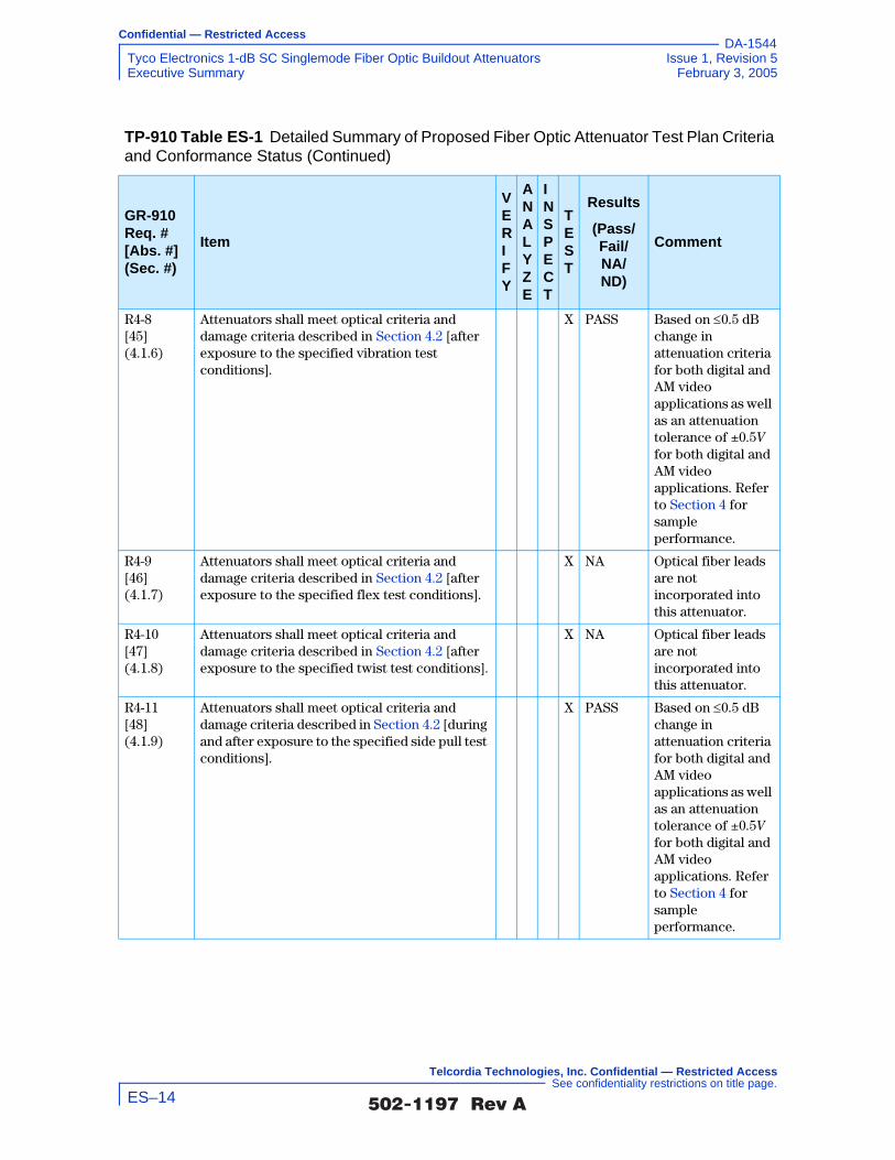
Confidential — Restricted Access
Tyco Electronics 1-dB SC Singlemode Fiber Optic Buildout Attenuators Issue 1, Revision 5Executive Summary February 3, 2005
DA-1544
R4-8 [45] (4.1.6)
Attenuators shall meet optical criteria and damage criteria described in Section 4.2 [after exposure to the specified vibration test conditions].
X PASS Based on ≤0.5 dB change in attenuation criteria for both digital and AM video applications as well as an attenuation tolerance of ±0.5V for both digital and AM video applications. Refer to Section 4 for sample performance.
R4-9 [46] (4.1.7)
Attenuators shall meet optical criteria and damage criteria described in Section 4.2 [after exposure to the specified flex test conditions].
X NA Optical fiber leads are not incorporated into this attenuator.
R4-10 [47] (4.1.8)
Attenuators shall meet optical criteria and damage criteria described in Section 4.2 [after exposure to the specified twist test conditions].
X NA Optical fiber leads are not incorporated into this attenuator.
R4-11 [48] (4.1.9)
Attenuators shall meet optical criteria and damage criteria described in Section 4.2 [during and after exposure to the specified side pull test conditions].
X PASS Based on ≤0.5 dB change in attenuation criteria for both digital and AM video applications as well as an attenuation tolerance of ±0.5V for both digital and AM video applications. Refer to Section 4 for sample performance.
TP-910 Table ES-1 Detailed Summary of Proposed Fiber Optic Attenuator Test Plan Criteria and Conformance Status (Continued)
GR-910 Req. # [Abs. #] (Sec. #)
Item
V E R I F Y
A N A L Y Z E
I N S P E C T
T E S T
Results
(Pass/ Fail/ NA/ND)
Comment
�������� �� ES–14
Telcordia Technologies, Inc. Confidential — Restricted Access See confidentiality restrictions on title page.

Confidential — Restricted Access
Issue 1, Revision 5 Tyco Electronics 1-dB SC Singlemode Fiber Optic Buildout AttenuatorsFebruary 3, 2005 Executive Summary
DA-1544
R4-12 [49] (4.1.10)
Attenuators shall meet optical criteria and damage criteria described in Section 4.2 [after exposure to the specified cable retention test conditions].
X PASS Based on ≤0.5 dB change in attenuation criteria for both digital and AM video applications as well as an attenuation tolerance of ±0.5V for both digital and AM video applications. Refer to Section 4 for sample performance.
R4-13 [50] (4.1.11)
Attenuators shall meet optical criteria and damage criteria described in Section 4.2 [after exposure to the specified durability test conditions].
X PASS Based on ≤0.5 dB change in attenuation criteria for both digital and AM video applications as well as an attenuation tolerance of ±0.5V for both digital and AM video applications. Refer to Section 4 for sample performance.
CR4-14 [51] (4.1.11)
The value of attenuation, as the attenuator setting is varied in either direction (including backlash) over the entire attenuation range, shall be within the attenuation tolerance, with no physical damage.
X NA
CR4-15 [52] (4.1.11)
Adjusting the setting past its endpoint by any amount shall not result in damage to the attenuator. Alternatively, there shall be a “stop” preventing adjustment past the endpoint.
X NA
TP-910 Table ES-1 Detailed Summary of Proposed Fiber Optic Attenuator Test Plan Criteria and Conformance Status (Continued)
GR-910 Req. # [Abs. #] (Sec. #)
Item
V E R I F Y
A N A L Y Z E
I N S P E C T
T E S T
Results
(Pass/ Fail/ NA/ND)
Comment
�������� �� ES–15
Telcordia Technologies, Inc. Confidential — Restricted Access See confidentiality restrictions on title page.

Confidential — Restricted Access
Tyco Electronics 1-dB SC Singlemode Fiber Optic Buildout Attenuators Issue 1, Revision 5Executive Summary February 3, 2005
DA-1544
R4-16 [53] (4.1.12)
Attenuators shall meet optical criteria and damage criteria described in Section 4.2 [after exposure to the specified impact test conditions].
X PASS Based on ≤0.5 dB change in attenuation criteria for both digital and AM video applications as well as an attenuation tolerance of ±0.5V for both digital and AM video applications. Refer to Section 4 for sample performance.
Optical Bandpass
CR4-17 [54] (4.2.1)
For 1310/1550nm attenuators to be used for all digital applications except long-reach SONET, all optical requirements shall be met over the bandpass for both the 1310nm and the 1550nm regions specified in GR-910 Table 4-3, Column 2.
X PASS
CO4-18 [55] (4.2.1)
For 1310/1550nm attenuators to be used for all digital applications, all optical objectives should be met over the bandpass for both the 1310 nm and the 1550nm regions specified in GR-910 Table 4-3, Column 3.
X PASS
CR4-19 [56] (4.2.1)
For 1310/1550nm attenuators to be used for long-reach SONET only, all optical requirements shall be met over the bandpass specified in GR-910 Table 4-3, Column 4.
X PASS
R4-20 [57] (4.2.1)
For all attenuators intended for use in AM-VSB video transmission, all optical requirements shall be met over the bandpass specified in GR-910 Table 4-3, Column 5.
X PASS
Change In Attenuation
CR4-21 [58] (4.2.2)
For all digital applications the maximum or minimum change in attenuation before, during, or after, any or all environmental or mechanical tests shall be ≤ 0.5 dB or ≤ 0.15A, whichever is less.
X PASS Based on ≤0.5 dB change in attenuation criteria.
TP-910 Table ES-1 Detailed Summary of Proposed Fiber Optic Attenuator Test Plan Criteria and Conformance Status (Continued)
GR-910 Req. # [Abs. #] (Sec. #)
Item
V E R I F Y
A N A L Y Z E
I N S P E C T
T E S T
Results
(Pass/ Fail/ NA/ND)
Comment
�������� �� ES–16
Telcordia Technologies, Inc. Confidential — Restricted Access See confidentiality restrictions on title page.

Confidential — Restricted Access
Issue 1, Revision 5 Tyco Electronics 1-dB SC Singlemode Fiber Optic Buildout AttenuatorsFebruary 3, 2005 Executive Summary
DA-1544
CR4-22 [59] (4.2.2)
For all AM video applications the maximum or minimum change in attenuation before, during, or after, any or all environmental or mechanical tests shall be ≤ 0.5 dB or ≤ 0.10A, whichever is less.
X PASS Based on ≤0.5 dB change in attenuation criteria.
Attenuation Tolerance
CR4-23 [60] (4.2.3)
For attenuators intended for use in digital applications the attenuation tolerance shall not exceed 0.15V.
X PASS Based on an attenuation tolerance of ±0.5V.
CR4-24 [61] (4.2.3)
For attenuators intended for use in AM video applications the attenuation tolerance shall not exceed 0.10V.
X PASS Based on an attenuation tolerance of ±0.5V.
Attenuation Increments and Range
R4-25 [62] (4.2.4)
The attenuation range for attenuators shall be at least ≤ 5 to 20 dB.
X PASS
CR4-26 [63] (4.2.4)
For digital applications the attenuation increments for fixed and discretely variable attenuators shall be ≤ 5 dB. This means that fixed and variable attenuators can change in increments of no greater than 5 dB.
X NA
CR4-27 [64] (4.2.4)
For AM video applications the attenuation increments for fixed and discretely variable attenuators shall be ≤ 3 dB.
X NA
CO4-28 [65] (4.2.4)
For AM video applications the attenuation increments for fixed and discretely variable attenuators shall be ≤ 1 dB.
X NA
CO4-29 [66] (4.2.4)
The attenuation range for attenuators should be at least ≤ 1 to 25 dB.
X PASS
Reflectance
R4-30 [67] (4.2.5)
The maximum reflectance for attenuators intended for use in Digital systems as bit rates up to 10 Gb/s shall be ≤ −40 dB over the entire bandpass of GR-910 R4-16 [53] and GR-910 CR4-17 [54] and operating temperature range of −40°C to 75°C (−40°F to 167°F).
X PASS
TP-910 Table ES-1 Detailed Summary of Proposed Fiber Optic Attenuator Test Plan Criteria and Conformance Status (Continued)
GR-910 Req. # [Abs. #] (Sec. #)
Item
V E R I F Y
A N A L Y Z E
I N S P E C T
T E S T
Results
(Pass/ Fail/ NA/ND)
Comment
�������� �� ES–17
Telcordia Technologies, Inc. Confidential — Restricted Access See confidentiality restrictions on title page.

Confidential — Restricted Access
Tyco Electronics 1-dB SC Singlemode Fiber Optic Buildout Attenuators Issue 1, Revision 5Executive Summary February 3, 2005
DA-1544
CR4-31 [68] (4.2.5)
The maximum reflectance for attenuators intended for use in AM-VSB systems shall be ≤ −55 dB over the entire bandpass of GR-910 CR4-19 [56] and operating temperature range of −40°C to +75°C.
X PASS
CO4-32 [69] (4.2.5)
The maximum reflectance for attenuators intended for use in AM-VSB systems should be ≤ −65 dB over the entire bandpass of GR-910 CR4-19 [56] and operating temperature range of−40°C to +75°C.
X FAIL Nonconforming conditions observed for all of the environmental and mechanical tests in all of the samples tested.
Polarization-Dependent Loss
R4-33 [70] (4.2.6)
All optical requirements shall be met for all incident SOPs.
X PASS
CR4-34 [71] (4.2.6)
For digital applications the maximum change in attenuation shall be ≤ 0.5 dB or ≤ 0.15A, whichever is less.
X PASS
CR4-35 [72] (4.2.6)
For AM video applications the maximum change in attenuation shall be ≤ 0.5 dB or ≤ 0.10A, whichever is less.
X PASS
Polarization-Mode Dispersion
CR4-36 [79] (4.2.7)
The maximum value of dispersion (in ps) shall not exceed 0.2 ps for all operating wavelengths.
X PASS
Damage Criteria
R4-37 [73] (4.2.8)
At the completion of all tests there shall be no damage that would impair the performance of the attenuator.
X PASS
Passive Optical Component Code (POCC)
R6-1 [74] (6.1)
The Passive Optical Component Code (POCC) characters as outlined in GR-910 Table 6-1 should be imprinted on the component housing.
X NA
TP-910 Table ES-1 Detailed Summary of Proposed Fiber Optic Attenuator Test Plan Criteria and Conformance Status (Continued)
GR-910 Req. # [Abs. #] (Sec. #)
Item
V E R I F Y
A N A L Y Z E
I N S P E C T
T E S T
Results
(Pass/ Fail/ NA/ND)
Comment
�������� �� ES–18
Telcordia Technologies, Inc. Confidential — Restricted Access See confidentiality restrictions on title page.
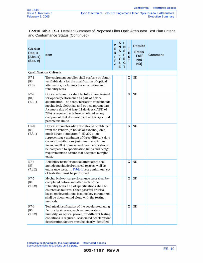
Confidential — Restricted Access
Issue 1, Revision 5 Tyco Electronics 1-dB SC Singlemode Fiber Optic Buildout AttenuatorsFebruary 3, 2005 Executive Summary
DA-1544
Qualification Criteria
R7-1 [80] (7.3)
The equipment supplier shall perform or obtain verifiable data for the qualification of optical attenuators, including characterization and reliability tests.
X ND
R7-2 [81] (7.3.1)
Optical attenuators shall be fully characterized for optical performance as part of device qualification. The characterization must include mechanical, electrical, and optical parameters. A sample size of at least 11 devices (LTPD of 20%) is required. A failure is defined as any component that does not meet all the specified parametric limits.
X ND
O7-3 [82] (7.3.1)
Optical attenuators data also should be obtained from the vendor (in-house or external) on a much larger population (~ 50-200 units representing a minimum of three different date codes). Distributions (minimum, maximum, mean, and 3σ) of measured parameters should be compared to specification limits and design requirements to assure that adequate margins exist.
X ND
R7-4 [83] (7.3.2)
Reliability tests for optical attenuators shall include mechanical/physical tests as well as endurance tests. … Table 1 lists a minimum set of tests that must be performed.
X ND
R7-5 [84] (7.3.2)
Mechanical/optical performance tests shall be completed before and after each of the reliability tests. Out of specifications shall be counted as failures. Other pass/fail criteria, based on degradations in some key parameters, shall be documented along with the testing methods.
X ND
R7-6 [85] (7.3.2)
Technical justification of the accelerated aging factors by stresses, such as temperature, humidity, or optical power, for different testing conditions is required. Associated acceleration/deceleration factors must be clearly identified.
X ND
TP-910 Table ES-1 Detailed Summary of Proposed Fiber Optic Attenuator Test Plan Criteria and Conformance Status (Continued)
GR-910 Req. # [Abs. #] (Sec. #)
Item
V E R I F Y
A N A L Y Z E
I N S P E C T
T E S T
Results
(Pass/ Fail/ NA/ND)
Comment
�������� �� ES–19
Telcordia Technologies, Inc. Confidential — Restricted Access See confidentiality restrictions on title page.

Confidential — Restricted Access
Tyco Electronics 1-dB SC Singlemode Fiber Optic Buildout Attenuators Issue 1, Revision 5Executive Summary February 3, 2005
DA-1544
R7-7 [86] (7.3.2)
For those components with non-hermetic packages, the thermal shock test will not be required, but the damp heat testing duration must be increased to 5000 hours from the 2000 hour test for hermetic components.
X NA
R7-8 [87] (7.3.2)
If technical data are not available in support of other values, an activation energy of 0.3 eV shall be assumed for the dry heat test and an effective activation energy of 0.6 eV shall be assumed for the damp heat test. In the latter case, the higher activation energy accounts for the difference between the test's high humidity and “average” operating conditions, such that a separate term for humidity would not be included in the calculation of the acceleration factor.
Manufacturers may use a different activation energy or a different model for calculating acceleration, if its use can be supported by empirical data. The empirical data must be based on reliability testing or field returns, and shall be available for review by the LECs, service providers or their representative.
X ND
O7-9 [88] (5.4.2.4)
In order of priority, the following life tests should be performed as part of any effort to validate alternative acceleration models or activation energies:
•High temperature damp heat = 75°C, 90% RH (or 85°C, 85% RH)
•High temperature dry heat = 85°C, ~ 16% RH
•Moderate temperature damp heat = 45°C, 85% RH
Minimum sample size is 22 devices for each life test. Results should include estimates of median life or mean-time-to-failure (MTTF), and a “spread” parameter (e.g., standard deviation).
X ND
TP-910 Table ES-1 Detailed Summary of Proposed Fiber Optic Attenuator Test Plan Criteria and Conformance Status (Continued)
GR-910 Req. # [Abs. #] (Sec. #)
Item
V E R I F Y
A N A L Y Z E
I N S P E C T
T E S T
Results
(Pass/ Fail/ NA/ND)
Comment
�������� �� ES–20
Telcordia Technologies, Inc. Confidential — Restricted Access See confidentiality restrictions on title page.

Confidential — Restricted Access
Issue 1, Revision 5 Tyco Electronics 1-dB SC Singlemode Fiber Optic Buildout AttenuatorsFebruary 3, 2005 Executive Summary
DA-1544
R7-10 [89] (7.3.2)
A temperature cycle life test shall be performed in accordance with the procedures of Section 6.2.7 in GR-1221-CORE. The minimum and maximum temperatures shall be at least –40°C and + 75°C. The minimum sample size is 11 devices (LTPD of 20%). Results after 500 cycles shall be used for “passing” or “failing” the test. Failures between 500 cycles and 1000 cycles shall be investigated and corrective actions shall be implemented.
X ND
R7-11 [90] (7.3.2)
Fiber pigtails and optical connectors shall comply with general flammability requirements for materials used in telecommunications systems.
X ND
Failure Rate Prediction
R7-12 [91] (7.3.3)
Equivalent time and temperature requirements shall be calculated using the Arrhenius relationship. Technical justification of the activation energy used for different conditions in temperature-dependent life tests is required.
Acceleration models (for failure mechanisms affected by other stresses, such as optical power or humidity) shall be demonstrated (theoretically if possible and empirically). Associated acceleration/deceleration factors must be clearly identified.
X ND
O7-13 [92] (7.3.3)
The acceleration aging factor from humidity is recommended to be assessed by the equation below. Technical justification of the derivation is required.
where H1 and H2 are the relative humidity levels in %, ML is the median life at a given humidity, and B and n are empirical constants.
X ND
R7-14 [93] (7.3.3)
Wear-out and random failure rates and acceleration aging factors shall be provided. The sources and data shall also be provided.
X X ND
TP-910 Table ES-1 Detailed Summary of Proposed Fiber Optic Attenuator Test Plan Criteria and Conformance Status (Continued)
GR-910 Req. # [Abs. #] (Sec. #)
Item
V E R I F Y
A N A L Y Z E
I N S P E C T
T E S T
Results
(Pass/ Fail/ NA/ND)
Comment
ML H2( )ML H1( )------------------------- BH1
n BH2n
–[ ]exp=
�������� �� ES–21
Telcordia Technologies, Inc. Confidential — Restricted Access See confidentiality restrictions on title page.

Confidential — Restricted Access
Tyco Electronics 1-dB SC Singlemode Fiber Optic Buildout Attenuators Issue 1, Revision 5Executive Summary February 3, 2005
DA-1544
O7-15 [94] (7.3.3)
To simplify review (by customers or their representatives) of failure rate predictions, the format in … Table 2 is recommended for use by device manufacturers and/or equipment suppliers.
X X ND
R7-16 [95] (7.3.3)
The testing data and supporting evidence for … Table 2 shall be documented and available for review at the request of a LEC, service provider or its representative.
X X ND
R7-17 [96] (7.3.3)
Unless otherwise specified, all failures observed in qualification testing must normally be counted and must be reported, regardless of the failure mode. Omission of any failures from test results must be clearly justified and must be reviewed with the LEC, service provider or its representative.
X X ND
O7-18 [97] (7.3.3)
… Table 3 provides the recommended format for reporting the status of all reliability tests.
X X ND
R7-19 [98] (7.3.3)
The testing data and supporting evidence for … Table 3 shall be documented and available for review at the request of a LEC, service provider or its representative.
X ND
Quality Assurance and Lot Controls
R7-20 [99] (7.3.5.1)
Incoming lots of optical attenuators shall be visually inspected on at least a sample basis (to be determined in accordance with a statistical sampling plan established by the equipment supplier).
X ND
O7-21 [100] (7.3.5.1)
Visual inspection (or another step in lot acceptance procedures) should check at least for the following:
•Package condition
•Required documentation
•Product appearance/condition
•Product identification/marking
•Inspection of connectors or fiber-pigtails.
X ND
TP-910 Table ES-1 Detailed Summary of Proposed Fiber Optic Attenuator Test Plan Criteria and Conformance Status (Continued)
GR-910 Req. # [Abs. #] (Sec. #)
Item
V E R I F Y
A N A L Y Z E
I N S P E C T
T E S T
Results
(Pass/ Fail/ NA/ND)
Comment
�������� �� ES–22
Telcordia Technologies, Inc. Confidential — Restricted Access See confidentiality restrictions on title page.

Confidential — Restricted Access
Issue 1, Revision 5 Tyco Electronics 1-dB SC Singlemode Fiber Optic Buildout AttenuatorsFebruary 3, 2005 Executive Summary
DA-1544
R7-22 [101] (7.3.5.2)
Parameters specified in Section 4 form the minimum set of optical parameters which must be guaranteed. If 100% testing for this purpose is not performed, adequate data shall be collected and a statistically justified sampling plan must be established. This sampling test program must be approved in writing from the LEC, service provider or its representative.
X ND
R7-23 [102] (7.3.5.3)
All optical attenuators shall be subjected to a temperature cycle screen. The minimum requirements consist of 10 cycles between temperature limits of at least –40°C and +75°C; if these are outside the component's specifications, the minimum- and maximum-specified storage temperatures shall be used.
X X ND
O7-24 [103] (7.3.5.3)
The demonstration of the effectiveness of alternate temperature cycle conditions for screening should include first characterizing devices after the proposed number of temperature cycles and again after 10 cycles, presumably showing that no significant degradation nor additional failures occurred. The demonstration should be proved on adequate samples over multiple lots.
X X ND
O7-25 [104] (7.3.5.3)
All optical attenuators should be subjected to a temperature humidity screen. The minimum requirement is 72 hours at +75°C and 90% RH.
X X ND
R7-26 [105] (7.3.5.3)
Optical criteria shall be measured before and after screening. Any “major” changes (as defined and documented by the equipment supplier, in addition to pass/fail criteria) shall result in rejection of a device.
X X ND
O7-27 [106] (7.3.5.3)
The pass/fail criteria should be no more than 20% changes on the specified parameters.
X ND
O7-28 [107] (7.3.5.3)
The manufacturer should record the optical criteria before and after screening on a sample of components as a production audit.
X ND
TP-910 Table ES-1 Detailed Summary of Proposed Fiber Optic Attenuator Test Plan Criteria and Conformance Status (Continued)
GR-910 Req. # [Abs. #] (Sec. #)
Item
V E R I F Y
A N A L Y Z E
I N S P E C T
T E S T
Results
(Pass/ Fail/ NA/ND)
Comment
�������� �� ES–23
Telcordia Technologies, Inc. Confidential — Restricted Access See confidentiality restrictions on title page.

Confidential — Restricted Access
Tyco Electronics 1-dB SC Singlemode Fiber Optic Buildout Attenuators Issue 1, Revision 5Executive Summary February 3, 2005
DA-1544
Quality and Reliability Criteria
R7-29 [108] (7.4)
The supplier shall, on request, make documentation available that describes:
•The quality program used in the manufacture of the product. This shall include but not be limited to controls, procedures and standards for component reliability assurance, incoming material inspection procedures, product manufacture, in-process testing, equipment calibration and maintenance, final product inspection and testing, initial and periodic qualification testing, and control of nonconforming materials/product. The component reliability assurance program shall address vendor selection/qualification, component qualification, and lot controls (incoming inspection, source inspection, and where appropriate, ship-to-stock practices).
•The installation, operation and maintenance of the product.
•Support procedures for the product once it is in use. This includes items such as repair, technical assistance, training and a means of notifying the customer of problems and/or changes in the product.
X ND
R7-30 [109] (7.4.1)
The supplier shall allow the performance of a Reliability Audit at the production facilities where the product is manufactured and assembled.
X ND
R7-31 [110] (7.4.1)
The supplier shall have a program in place to monitor both the early-life and long-term reliability of the product. The program shall include documented procedures for analysis, testing, and measurement of reliability. The reliability data shall be made available on request.
X ND
TP-910 Table ES-1 Detailed Summary of Proposed Fiber Optic Attenuator Test Plan Criteria and Conformance Status (Continued)
GR-910 Req. # [Abs. #] (Sec. #)
Item
V E R I F Y
A N A L Y Z E
I N S P E C T
T E S T
Results
(Pass/ Fail/ NA/ND)
Comment
�������� �� ES–24
Telcordia Technologies, Inc. Confidential — Restricted Access See confidentiality restrictions on title page.

Confidential — Restricted Access
Issue 1, Revision 5 Tyco Electronics 1-dB SC Singlemode Fiber Optic Buildout AttenuatorsFebruary 3, 2005 Executive Summary
DA-1544
R7-32 [111] (7.4.2)
The supplier's manufacturing process and associated quality assurance systems, as they relate to products covered by this document, shall be subject to periodic quality process and finished product audits.
X ND
TP-910 Table ES-1 Detailed Summary of Proposed Fiber Optic Attenuator Test Plan Criteria and Conformance Status (Continued)
GR-910 Req. # [Abs. #] (Sec. #)
Item
V E R I F Y
A N A L Y Z E
I N S P E C T
T E S T
Results
(Pass/ Fail/ NA/ND)
Comment
�������� �� ES–25
Telcordia Technologies, Inc. Confidential — Restricted Access See confidentiality restrictions on title page.

Confidential — Restricted Access
Tyco Electronics 1-dB SC Singlemode Fiber Optic Buildout Attenuators Issue 1, Revision 5Executive Summary February 3, 2005
DA-1544
�������� �� ES–26
Telcordia Technologies, Inc. Confidential — Restricted Access See confidentiality restrictions on title page.

Confidential — Restricted Access
Issue 1, Revision 5 Tyco Electronics 1-dB SC Singlemode Fiber Optic Buildout AttenuatorsFebruary 3, 2005 Program Scope
DA-1544
Program Scope
The scope of this program is comprehensive and includes all essential elements required under GR-910-CORE (Issue 2). Telcordia verifies, analyzes, inspects and tests Tyco Electronics Corporation’s 1-dB SC Singlemode Fiber Optic Buildout Attenuators to determine conformance to each essential Requirement (R), Objective (O), Conditional Requirement (CR), and Conditional Objective (CO). A complete list of the criteria to be evaluated is included as TP-910 Table ES-1 located in the Executive Summary section of this Test Report. Any criteria that may not be applicable to a specific product will be denoted as “NA” in TP-910 Table ES-1, and the reason will be stated.
For vendors of Verizon, the requirements specified herein shall be accomplished at either a certified PFOC ITL or at an approved PFOC ITL client site under the surveillance of PFOC ITL.
Test Report Format
It is the intent of this Test Plan for it to be converted to a Test Report for delivery to the client at the completion of the test program. In this way, a uniform correlation will be maintained between the GR-910-CORE Generic Requirements document, the Telcordia Test Plan, and the Test Report. It is an essential requirement of
Verizon for there to be a one-to-one mapping between GR-910-CORE Issue
2 and this document for Section 3 (General and Design Criteria), Section 4
(Performance Criteria) and Section 7 (Reliability and Quality Assurance
Program). Section 1 of GR-910-CORE is administrative in nature and does
not contain criteria or require testing, and therefore it is not required or
included in this document. Section 2 of GR-910-CORE does not include
criteria or require any testing, but it does provide useful background
information on passive optical components. Therefore, it is included in this
document. Section 5 of GR-910-CORE describes the test procedures for the
performance analysis of single-mode fiber optic attenuators which are used
within the content of Section 4. Finally, Section 6 of GR-910-CORE
contains the Telcordia Passive Optical Component Code (POCC)
description format which offers a quick reference to mechanical, electrical,
and optical definitions.
For any case where Telcordia will not be evaluating Reliability criteria, Section 7 of GR-910-CORE may be reduced to a statement to describe why they were not evaluated by Telcordia (if this is a Verizon PFOC ITL, Verizon should be notified in advance).
�������� �� PS–1
Telcordia Technologies, Inc. Confidential — Restricted Access See confidentiality restrictions on title page.

Confidential — Restricted Access
Tyco Electronics 1-dB SC Singlemode Fiber Optic Buildout Attenuators Issue 1, Revision 5Program Scope February 3, 2005
DA-1544
Program Initiation Flowchart
The process for initiation of a program under GR-910-CORE is illustrated in the flow chart shown in TP-910 Figure PS-1 below:
TP-910 Figure PS-1 Program Initiation Flowchart
Receipt of Signed Service
Order
Legal and Technical Review; Processing
by Billing Organization to establish project numbering codes
Project Leader and team assigned
Project Documentation File
Formally Established
Kickoff discussion with client to establish roles, responsibilities
and project action items
Client provides product samples for
test and required documentation
Test Plans Prepared and Proposed Schedule is Established
Test Plans reviewed by client and client
customers if needed (req’d for Verizon
programs)
Test plans comments reflected in updated test plan as required
Testing and Documentation
Review Phase Begins
Process Discussion held at client site to review and verify
documented processes as required
to establish conformance to
general requirements
Samples Selected for
Testing
Perform all required tests for GR-910-CORE Section 4
Analyze supplier documentation and
results of onsite process audit
Record all findings relative
to test and measurement related criteria
Record all findings relative
to general criteria
conformance
Completion of Section 3 and 7
of Analysis Report
Complete Section 4 of
Analysis Report
�������� �� PS–2
Telcordia Technologies, Inc. Confidential — Restricted Access See confidentiality restrictions on title page.

Confidential — Restricted Access
Issue 1, Revision 5 Tyco Electronics 1-dB SC Singlemode Fiber Optic Buildout AttenuatorsFebruary 3, 2005 Program Scope
DA-1544
High-Level Flowchart for Service Life and General Requirements Evaluation/Test Program
The overall flow for the entire GR-910-CORE PFOC program is illustrated in the high-level flow chart shown in TP-910 Figure PS-2. This chart shows each major step required to assess conformance, and is not intended to demonstrate the most efficient or actual path for completion.
�������� �� PS–3
Telcordia Technologies, Inc. Confidential — Restricted Access See confidentiality restrictions on title page.

Confidential — Restricted Access
Tyco Electronics 1-dB SC Singlemode Fiber Optic Buildout Attenuators Issue 1, Revision 5Program Scope February 3, 2005
DA-1544
TP-910 Figure PS-2 High-Level Flowchart for Service Life and General Requirements Evaluation/Test Program
Samples Received, Uniquely Identified and Inspected for
Condition
Section 3 - General and
Design Criteria
Section 3.1 - Documentation
Section 3.2 - Marking,
Packaging and Shipping
Section 3.3 - Physical Design
Criteria
Check Calibration of all test equipment to
be used for measurements
Set Up of the Standard Test Configuration
Perform preparation and warm up of
specific systems in accordance with
manuals/instructions
Section 4 - Performance
Criteria
Section 4.1 - Environmental
and Mechanical Criteria
Section 4.1.1 - Controlled Operating
Environment
Section 4.1.2 - Uncontrolled
Operating Environment
Section 4.1.3 - Non-Operating Environment
Section 4.1.4 - Humidity/
Condensation Cycling
Section 4.1.5 - Water
Immersion
Section 4.1.6 - Vibration
Section 4.1.9 - Side Pull
Section 4.1.10 - Cable Retention
Section 4.1.11 - Durability
Section 4.1.12 - Impact
Section 4.2 - Optical Criteria
Section 4.2.1 - Optical Bandpass
Section 4.2.2 - Change in Attenuation
Section 4.2.3 - Attenuation Tolerance
Section 4.2.5 - Reflectance
Section 4.2.6 - PDL
Section 4.2.7 - PMD
Section 4.2.8 - Damage Criteria
Analyze all results and
complete report preparation
�������� �� PS–4
Telcordia Technologies, Inc. Confidential — Restricted Access See confidentiality restrictions on title page.

Confidential — Restricted Access
Issue 1, Revision 5 Tyco Electronics 1-dB SC Singlemode Fiber Optic Buildout AttenuatorsFebruary 3, 2005 Administrative Data (not from GR-910)
DA-1544
1.0 Administrative Data (not from GR-910)
1.1 Description of Test Item(s) (not from GR-910)
Buildout attenuators are 2 port, bidirectional components without integral optical fiber leads. These attenuators were manufactured to an attenuation tolerance of 1 ±0.5 dB and ≥55 dB return loss.
1.2 Part Number(s) and Serial Number(s) of Test Item(s) (not from GR-910)
Product part number: 209250-1
Serial numbers of tested samples including hot spares are correlated to sample numbers as follows:
1.3 Location(s) of Manufacturing (not from GR-910)
3/F No. 138 He Dan Road Waigaoqiao Free Trade Zone Shanghai 200131, China
TP-910 Table 1-1 Sample Name and Serial Number of Tested Samples, Hot Spares
Test Sample Name
Test Sample Serial Number
Hot Spare Serial Number
i.l.01 6 11
i.l.02 23 12
i.l.03 25 22
i.l.04 26 30
i.l.05 28 41
i.l.06 31 42
i.l.07 33 46
i.l.08 37 48
i.l.09 44 994
i.l.10 52 997
i.l.11 969 1000
�������� �� 1–1
Telcordia Technologies, Inc. Confidential — Restricted Access See confidentiality restrictions on title page.

Confidential — Restricted Access
Tyco Electronics 1-dB SC Singlemode Fiber Optic Buildout Attenuators Issue 1, Revision 5Administrative Data (not from GR-910) February 3, 2005
DA-1544
1.4 Test/Evaluation Location(s) and Dates (not from GR-910)
Telcordia Technologies Raritan River Software Systems Center One Telcordia Drive Piscataway, NJ 08844-4157 Laboratory: RRC-1D169 Laboratory: RRC-1D183
Testing/Evaluation commenced on: April 12, 2004 Testing/Evaluation concluded on: August 3, 2004
1.5 References (not from GR-910)
Telcordia References
• BR 781-826-127, Optical Cross-Connect Planning (A Module of the OXPEG)
• GR-63-CORE, Network Equipment-Building System (NEBS) Generic
Equipment Requirements
• GR-253-CORE, Synchronous Optical Network (SONET) Transport Systems:
Common Generic Criteria, (A Module of TSGR, FR-440)
• TR-NWT-000264, Optical Fiber Cleavers
• GR-326-CORE, Generic Requirements for Single-Mode Optical Connectors and
Jumper Assemblies
• TR-NWT-000357, Generic Requirements for Assuring the Reliability of
Components used in Telecommunications Equipment
• GR-409-CORE, Generic Requirements for Premises Fiber Optic Cable
• GR-765-CORE, Generic Requirements for Single Fiber Optical Splices and
Systems
• TA-NWT-000909, Generic Requirements and Objectives for Fiber In The Loop
Systems
• GR-1209-CORE, Generic Requirements for Passive Optical Components
• GR-1221-CORE, Generic Reliability Assurance Requirements for Fiber Optic
Branching Components
• GR-1252-CORE, Quality System Generic Requirements for Hardware (A Module of RQGR, FR-796).
• SR-NWT-001907, Transport Reliability Analysis Generic Guidelines (TRAGG)
• SR-NWT-002014, Suggested Optical Cable Code (SOCC)
�������� �� 1–2
Telcordia Technologies, Inc. Confidential — Restricted Access See confidentiality restrictions on title page.
Confidential — Restricted Access
Issue 1, Revision 5 Tyco Electronics 1-dB SC Singlemode Fiber Optic Buildout AttenuatorsFebruary 3, 2005 Administrative Data (not from GR-910)
DA-1544
• SR-NWT-2759, A View of Packaging, Packing, Palletization, and Marking
Requirements
Electronic Industries Association (EIA) References
The EIA/TIA-455 documents (the official document numbers) are more commonly known as FOTPs (for Fiber Optic Test Procedures), and are referred to as such in the text of this document.
• EIA/TIA-455-A, Standard Test Procedures for Fiber Optic Fibers, Cables,
Transducers, Sensors, Connecting and Terminating Devices, and Other Fiber
Optic Components
• EIA/TIA-455-1A, FOTP-1: Cable Flexing for Fiber Optic Interconnecting
Devices
• EIA/TIA-455-2B, FOTP-2: Impact Test Measurements for Fiber Optic Devices
• EIA/TIA-455-3A, FOTP-3: Procedure to Measure Temperature Cycling Effects
on Optical Fibers, Optical Cable, and Other Passive Fiber Optic Components
• EIA/TIA-455-5A, FOTP-5: Humidity Test Procedure for Fiber Optic
Connecting Devices
• EIA/TIA-455-6A, FOTP-6: Cable Retention Test Procedure For Fiber Optic
Cable Interconnecting Devices
• EIA/TIA-455-11, FOTP-11: Vibration Test Procedure For Fiber Optic
Connecting Devices
• EIA/TIA-455-12A, FOTP-12: Fluid Immersion Test for Fiber Optic Components
• EIA/TIA-455-13, FOTP-13: Visual and Mechanical Inspection of Fiber Optic
Devices
• EIA/TIA-455-20A, FOTP-20: Measurement of Change In Optical
Transmittance
• EIA/TIA-455-36, FOTP-36: Twist Test For Fiber Optic Connecting Devices
• EIA/TIA-455-57, FOTP-57: Optical Fiber End Preparation and Examination
• EIA/TIA-455-78, FOTP-78: Spectral Attenuation Cutback Measurement for
Single-Mode Optical Fibers
• EIA/TIA-455-107, FOTP-107: Return Loss for Fiber Optic Components
• EIA/TIA-455-127, FOTP-127: Spectral Characterization of Multimode Lasers
Other References
• ASTM B117, Salt Spray (Fog) Testing
�������� �� 1–3
Telcordia Technologies, Inc. Confidential — Restricted Access See confidentiality restrictions on title page.

Confidential — Restricted Access
Tyco Electronics 1-dB SC Singlemode Fiber Optic Buildout Attenuators Issue 1, Revision 5Administrative Data (not from GR-910) February 3, 2005
DA-1544
• ASTM D610, Standard Method of Evaluating Degree of Rusting on Painted
Steel Surfaces
• ASTM D2863, Standard Method for Measuring the Minimum Oxygen
Concentration to Support Candle-Like Combustion of Plastics (Oxygen
Index)
• ASTM G21, Determining Resistance of Polymeric Material to Fungi
• MIL-M-38510J, General Specification for Microcircuits, Military Specification, (November 1991)
• UL 94, Tests for Flammability of Plastic Materials for Parts in Devices and
Appliances
Optical Safety References
• ANSIZ136.2, American National Standard for the Safe Use of Optical Fiber
Communications Systems Utilizing Laser Diode and LED Sources, 1997.
• FDA 79-8035, United States Food and Drug Administration, Bureau of
Radiological Health Laser Product Safety Classifications, 21 CFR 1040, August 20, 1985.
�������� �� 1–4
Telcordia Technologies, Inc. Confidential — Restricted Access See confidentiality restrictions on title page.

Confidential — Restricted Access
Issue 1, Revision 5 Tyco Electronics 1-dB SC Singlemode Fiber Optic Buildout AttenuatorsFebruary 3, 2005 General Information
DA-1544
2.0 General Information
2.1 General Product Description
A fiber optic attenuator is a passive, in-line, optical component that intentionally reduces (attenuates) the optical power propagating in fiber. GR-910 Figure 2-1a) shows a schematic representation of a Fixed Attenuator and GR-910 Figure 2-1b) shows a Variable Attenuator.
Variable attenuators may adjust power continuously or in discrete steps. The ideal attenuator has a stable attenuation over a wide temperature range and mechanical stress. It is independent of wavelength and state of polarization, and causes no reflection or interference of the optical signal. In addition, a variable attenuator should have small attenuation increments, wide attenuation range, and accurate control of attenuation.
2.2 Attenuator Technology
Manufacturing technology is not considered in detail here, other than to describe some of the methods used to produce attenuators. In an all-fiber attenuator1, a Ge-Al co-doped silica core attenuation fiber is cleaved at a specific length and fusion spliced between two standard single-mode fibers. The attenuator is epoxied into ferrules that are polished and packaged appropriately. In fused tapered attenuators a tapered region of a specific length is produced by heating and pulling the fiber. The tapered region is epoxied and packaged in a protective housing, ready for connectorization or fusion splicing.
Several physical phenomena can be utilized to fabricate fixed and variable attenuators, including divergence of light (in an air-gap attenuator), light absorption or scattering through a partially opaque film or filtering material, reflection from, (a bend radius, refractive index discontinuity, or at an angled surface), and optical polarization. Air-gap attenuators inherently have high reflections and can cause systems power penalties in high bit rate systems. Currently there are commercially
GR-910 Figure 2-1 The a) Fixed and b) Variable Attenuator Components
1. Chia, Shin-Lo, Cost-effective Single-Mode wavelength independent all-fiber attenuator, NFOEC June 1992.
�������� �� 2–1
Telcordia Technologies, Inc. Confidential — Restricted Access See confidentiality restrictions on title page.

Confidential — Restricted Access
Tyco Electronics 1-dB SC Singlemode Fiber Optic Buildout Attenuators Issue 1, Revision 5General Information February 3, 2005
DA-1544
available attenuators that attenuate optical power via bend radius that do not increase optical reflectance. These bend radius attenuators are currently designed for the 1310 nm wavelength region. Further study needs to be undertaken to evaluate the long term effects of small bend radii on optical fiber.
Both fixed and variable attenuators for use in fiber optic transmission systems will be considered in this GR. Both types of attenuators can be used for BER characterization of transmission systems by representing system power penalties.
• Fixed Attenuator An attenuator having a constant, non-adjustable value of attenuation. Attenuation can be changed only by removing and replacing or by concatenating fixed attenuators.
• Variable AttenuatorsAn attenuator that has a variable attenuation, varied with an integral adjustment that can be either calibrated or uncalibrated
Attenuators may or may not have attached optical fiber pigtails, but attenuators without fiber pigtails have either integral connector receptacles or optical connector interfaces, for coupling to connectorized fiber cables. There are three basic types of in-line attenuators: connector receptacle, optical pad, and patchcord attenuators. Connector receptacles include bulkhead, barrel build-out, sleeve, adaptor, or coupling. The connector receptacle attenuating element is either an air-gap or filter and is part of the receptacle. Attenuators with male/female connector interfaces attached to the body of the attenuator are referred to as optical pad attenuators and look much like electrical pad attenuators. A patchcord attenuator has one or two permanently attached fiber pigtails, which may or may not be connectorized. The attenuating element in optical pad and patchcord attenuators is a filter, a chemically etched fiber, or a fused tapered fiber. See GR-910 Figure 2-2 for examples of types of attenuators.
GR-910 Figure 2-2 Attenuator Types a) Connector Receptacle, b) Optical Pad, c) Patchcord
�������� �� 2–2
Telcordia Technologies, Inc. Confidential — Restricted Access See confidentiality restrictions on title page.

Confidential — Restricted Access
Issue 1, Revision 5 Tyco Electronics 1-dB SC Singlemode Fiber Optic Buildout AttenuatorsFebruary 3, 2005 General Information
DA-1544
The requirements of this document are intended for attenuators with single-mode input and single-mode or multimode output, at nominal wavelengths of 1310 nm and 1550 nm. An air-gap attenuator, used to couple light from single-mode fiber to multimode fiber, typically has a lower attenuation than it would have for coupling light between single-mode fibers, because multimode fiber is able to capture more diverging light. These attenuators are needed when multimode fiber is used to connect the receiver input from a single-mode transmission link.
The non-mechanical control of attenuation, where an electrical (or magnetic) input signal directly varies the optical attenuation, may be advantageous. For example, liquid crystals rotate the polarization of light depending on an applied voltage. Combined with a polarizing beam-splitter, polarization independent, electrically variable attenuation is possible. Electro-optic attenuators are available that are designed to control power in optical amplifiers used in Wavelength Division
Multiplexer (WDM) systems. However, electrically, magnetically, acoustically, or optically variable attenuators are not be considered in this issue. However, as this technology becomes available it may be necessary to include these technologies in future issues of GR-910-CORE as the technology matures. Attenuators designed for use in test or laboratory instruments (not designed to remain as part of a transmission system) will also not be considered. This document considers only passive optical attenuators that are intended for use in telecommunications systems.
2.3 Attenuator Applications
Attenuators are used in fiber-optic transmission systems to reduce the optical power received by the photodetector to a level that is within the dynamic range of the optical receiver. The light intensity control of laser diodes and LEDs is limited in dynamic range and can result in an undesired change in radiation pattern, modal structure and central wavelength. Light intensity control at the transmitter has the additional disadvantage of requiring either remote power monitoring at the destination central office (CO) receiver or loop-back. Therefore, for interoffice transmission applications, attenuators are normally deployed at the destination CO, immediately in front of the receiver. A fixed value of attenuation is often adequate to adjust the received power level to within the required range.
GR-910 Figure 2-3 shows a fiber optic transmission system with a variable attenuator in front of the receiver. Such attenuators are useful for periodic adjustment of received power should the link loss output power increase or decrease during the life of the transmission system. Increased link loss may be caused by degradation of the fiber, splices, or optical connectors. Variable attenuators are also important for making optical measurements, such as BER as a function of received power, which are important for characterizing the performance of transmission systems.
�������� �� 2–3
Telcordia Technologies, Inc. Confidential — Restricted Access See confidentiality restrictions on title page.

Confidential — Restricted Access
Tyco Electronics 1-dB SC Singlemode Fiber Optic Buildout Attenuators Issue 1, Revision 5General Information February 3, 2005
DA-1544
Fiber-optic attenuators may be used in central offices or in outside enclosures such as cabinets, huts, or underground vaults, and are intended for use in both controlled and uncontrolled environments. Outside plant applications may involve locating attenuators underground in subsurface enclosures which may be subject to flooding, on outdoor walls, or on utility poles. The closures which enclose them may be “free breathing” or they may be hermetic. Free-breathing closures will subject them to temperature and humidity swings, possible condensation, and possible biological action from airborne bacteria, insects, etc. Hermetic closures will subject the attenuators within to temperature swings unless they are breached. Attenuators in the underground plant may be subjected to groundwater immersion if closures containing them are breached or improperly assembled.
A new application for attenuators is controlling gain in Ebrium Doped Fiber
Amplifiers (EDFA) and optical power in Dense WDM (DWDM) systems. These are electro-optic attenuators that operate in the 1550 nm wavelength region. Electro-optic attenuators are not covered in this document, but may be included in future issues.
2.3.1 Environmental Conditions
A central office/node2 has a controlled environment with an ambient temperature from 4°C to 38°C, and short-term ambient temperature for −5°C to 50°C, as stated in Telcordia document GR-63-CORE. Short-term is defined as a period of not more than 72 consecutive hours and a total of not more than 15 days in one year. Remote sites and customer premises can have the same environment as a central office, as in a controlled environment vault (CEV), or an uncontrolled environment, as in an above-ground cabinet. In an uncontrolled environment, transmission systems must operate over a temperature range from −40°C with no solar load to 46°C with maximum solar load and power dissipation and a relative humidity of 5 to 95% for the projected length of service. The worst-case operating temperature range for passive components is defined as -40°C to 75°C with a relative humidity of 90 ± 5% RH (75°C is obtained by assuming the maximum solar load and power dissipation results in a 29°C increase of the component above the maximum ambient temperature of 46°C).
GR-910 Figure 2-3 Optical Transmission Using a Variable Attenuator.
2. Including remote nodes and customer premises.
TX RXdB
�������� �� 2–4
Telcordia Technologies, Inc. Confidential — Restricted Access See confidentiality restrictions on title page.

Confidential — Restricted Access
Issue 1, Revision 5 Tyco Electronics 1-dB SC Singlemode Fiber Optic Buildout AttenuatorsFebruary 3, 2005 General Information
DA-1544
Due to the difficulty of providing electrical power, the optical source at the ONU is unlikely to have temperature control. This means that source wavelength can vary with ambient temperature according to GR-910 Figure 2-4.
The shift in emission wavelength amounts to ~ 0.7°C and is roughly linear with temperature. All optical sources are required to operate within the wavelength range shown in gray. The optical bandpass objective for attenuators is designed to
match this wavelength range. The intent is to make generic attenuator components compatible with all transmission equipment, regardless of environment.
2.4 Recommended Methods and Procedures (not from GR-910)
• CAUTION: Handle all cabling with care. Avoid handling damaged cables
with bare hands.
NOTE: FOR A MULTI-PORT DEVICE, ALL THE PORTS MUST BE
SUBJECTED TO OPTICAL, ENVIRONMENTAL AND MECHANICAL
TESTS.
Sections 3 through 7 of this test plan lists test conditions and outlines of recommended test procedures. These methods and procedures are recommended only. Telcordia recognizes that there are equivalent methods and procedures that can be used to determine conformance or nonconformance. These methods and procedures are used in Telcordia testing facilities and will be used in comparison during witness testing.
GR-910 Figure 2-4 Central Wavelength Variation of Uncontrolled Optical Source
�������� �� 2–5
Telcordia Technologies, Inc. Confidential — Restricted Access See confidentiality restrictions on title page.

Confidential — Restricted Access
Tyco Electronics 1-dB SC Singlemode Fiber Optic Buildout Attenuators Issue 1, Revision 5General Information February 3, 2005
DA-1544
2.5 Test Equipment (not from GR-910)
Equipment that may be used to perform the testing of passive fiber optic components is listed in the Test Apparatus section for each individual test performed. The equipment used may differ from the particular equipment listed, but must be equivalent to that equipment. For operating instructions on any particular test equipment, please refer to the manufacturer’s user manual. Typical test setups and facilities are described in the sections associated with the individual criteria, as needed for the performance of the testing.
2.6 Optical Data Guidelines (not from GR-910)
2.6.1 Acquisition of Optical Data (not from GR-910)
The following guidelines apply to the collection of data:
• A minimum of four reference transmission paths will be monitored during testing to determine the stability of the test system. The transmission paths will consist of splice(s), identical fiber media of the same length spliced to the samples, and adjacent optical switch channels
• A reflectance reference with a value of –60 dB shall be monitored during the testing
• All the optical equipment used for measuring characteristics of the component must be referenced out prior to the actual measurements
• The data is to be collected via software-controlled data acquisition systems, where applicable
• All guidelines mentioned in Section 4 of GR-910-CORE, Issue 2 must be followed for the applicable component type.
2.6.2 Analysis of Optical Data (not from GR-910)
The optical performance data will consist of initial, during, and post values for the applicable characteristic at applicable wavelengths. The average value of the references will be used to normalize the measured values. Each unit tested will be included in the test report.
2.7 Test Sequence and Schedule (not from GR-910)
TP-910 Table 2-1 below lists the test sequences and approximate duration to perform the tests required in a GR-910 analysis. Test durations are based on the estimated test execution time, as test setup and sample preparation time can vary depending on test equipment availability and level of sample preparedness
�������� �� 2–6
Telcordia Technologies, Inc. Confidential — Restricted Access See confidentiality restrictions on title page.

Confidential — Restricted Access
Issue 1, Revision 5 Tyco Electronics 1-dB SC Singlemode Fiber Optic Buildout AttenuatorsFebruary 3, 2005 General Information
DA-1544
performed by the supplier when submitting the samples for test. Analysis of conformance to the General Requirements, which are verification based and do not require specific tests to be performed, will be conducted in parallel to those criteria that are addressed via testing. A draft test report is developed in parallel to all testing, incorporating results as tests are completed, and the full draft report is planned to be completed within two weeks of completion of all testing.
TP-910 Table 2-1 Testing Sequences and Estimated Durations
Test TitleGR-910 Section
Estimated Duration
1 Environmental and Mechanical Criteria
4.1
2 Controlled Operating Environment 4.1.1 8 days
3 Uncontrolled Operating Environment 4.1.2 8 days
4 Non-Operating Environment 4.1.3 15 days
5 Humidity/Condensation Cycling Test 4.1.4 8 days
6 Water Immersion 4.1.5 8 days
7 Vibration 4.1.6 1-2 days
8 Flex Test 4.1.7 1-2 days
9 Twist Test 4.1.8 1-2 days
10 Side Pull Load 4.1.9 2-3 days
11 Cable Retention 4.1.10 3-4 days
12 Durability 4.1.11 5 days
13 Impact Test 4.1.12 1-2 days
14 Optical Criteria 4.2
15 Optical Bandpass 4.2.1 1-2 days
16 Change in Attenuation 4.2.2 NA
17 Attenuation Tolerance 4.2.3 1 day
18 Attenuation Increments and Range 4.2.4 1 day
19 Reflectance 4.2.5 1 day
20 Polarization-Dependent Loss (PDL) 4.2.6 1 day
21 Polarization-Mode Dispersion (PMD) 4.2.7 1 day
22 Damage Criteria 4.2.8 NA
23 Documentation 3.1 1 day
24 Marking, Packaging and Shipping 3.2 1 day
25 Physical Design Criteria 3.3 3 days
26 Qualification Criteria 7.3 1 day
27 Quality and Reliability Criteria 7.4 3 days
�������� �� 2–7
Telcordia Technologies, Inc. Confidential — Restricted Access See confidentiality restrictions on title page.

Confidential — Restricted Access
Tyco Electronics 1-dB SC Singlemode Fiber Optic Buildout Attenuators Issue 1, Revision 5General Information February 3, 2005
DA-1544
2.8 Test Samples
NOTE: All ports must be subjected to the full suite of GR-910 tests
Per Verizon requirements, a minimum of eleven (11) module test samples shall be required for statistical sampling purposes. Suppliers may elect at their option to test a higher number of samples, however eleven samples will be the minimum to remain in accord with Verizon specifications.
The length of individual, unconnectorized fiber leads shall be a minimum of two (2) meters in length to provide adequate slack for splicing. In some intra-office (CO) applications, passive optical components may be needed with leads long enough to span the gap between distributing frames.
For passive optical components intended to serve as interconnects or cross-connects between the Outside Plant (OSP) panel and the network equipment, the length of individual connectorized fiber pigtails should be at least two (2) meters in length.
Customer shall provide twenty five (25) fiber optic attenuator samples. From these 25 samples, Telcordia will choose eleven (11) test samples randomly for optical testing and eleven (11) hot spares, to be used in the event of non-conformance(s).
Per Verizon requirements, the supplier shall provide their recommended chassis/cabinet/housing with the mountable device, if applicable, for vibration and shock testing. If devices need to be spliced, detailed documentation on the mounting procedure shall be provided.
As previously noted, all ports are intended to be tested. Customer shall however provide terminators to be available in the event that any ports are disconnected for any reason in the execution of any of the testing.
Reliability test sample sizes will be confirmed with Verizon prior to any related GR-1221 reliability testing done in concurrence with the GR-910 tests.
�������� �� 2–8
Telcordia Technologies, Inc. Confidential — Restricted Access See confidentiality restrictions on title page.

Confidential — Restricted Access
Issue 1, Revision 5 Tyco Electronics 1-dB SC Singlemode Fiber Optic Buildout AttenuatorsFebruary 3, 2005 General and Design Criteria
DA-1544
3.0 General and Design Criteria
Generic requirements are identified by the word “shall” and denoted by GS-N, where G is an R, O, CR, or CO, S is the section number and N is the number of the criterion within the section. In addition, the criterion is marked with a number in brackets [] that corresponds to the criterion number within the entire document. Refer to Section 1.3 of GR-910-CORE for further explanation of requirements and objectives.
3.1 Documentation
Requirements on product documentation are twofold: general and user-specific.
3.1.1 General Documentation
General documentation includes all information a customer needs to select, order and use a product. This type of information is typically found in product literature such as catalogs, sales brochures, manuals, product data, and instructions sheets.
3.1.1.1 Criteria - General Documentation (heading not from GR-910)
GR-910 R3-1 [1] On request, the supplier shall provide a complete set of documentation that includes:
• Product Description
— General features
— Manufacturer name, model number and date made
— Type of attenuator, fixed or variable
— Attenuator component termination (e. g., pigtail, connector type)
— Fiber-type
— Description of attenuating element (e. g., filter, type of fiber)
— Applications.
• Performance Specifications
— Increments and range of attenuation
— Optical characteristic in Section 4.2 (attenuation tolerance, bandpass, reflectance and polarization)
— Storage environment temperature and humidity range
— Maximum fiber and fiber cable retention, flex, and twist force
�������� �� 3–1
Telcordia Technologies, Inc. Confidential — Restricted Access See confidentiality restrictions on title page.

Confidential — Restricted Access
Tyco Electronics 1-dB SC Singlemode Fiber Optic Buildout Attenuators Issue 1, Revision 5General and Design Criteria February 3, 2005
DA-1544
— Thermal stability
— Humidity resistance
— Vibration stability
— Impact resistance
— Resistance to airborne contaminants.
• Installation Instructions
— Component dimensions
— Tools necessary for installation
— Mounting features, conditions, and location in relation to other system components
— Safety precautions
— Test equipment and testing methods to be used when the item is provisioned.
• Operating Instructions
— Use and handling including optical connector mating and splicing.
• Maintenance
— Cleaning instructions
— Routine maintenance schedule
— Instructions to identify the effects of faults and the methods used to isolate a problem
— Service and service contact information.
• Ordering Information
— Model numbers
— Connector interface options
— Available fiber types, lengths, and mode field diameter
— Mounting options
— Package configuration & package material options
— All other options.
• Testing and troubleshooting procedure
• Repair instructions and contact for repair service
• Storage and transportation instructions.
�������� �� 3–2
Telcordia Technologies, Inc. Confidential — Restricted Access See confidentiality restrictions on title page.

Confidential — Restricted Access
Issue 1, Revision 5 Tyco Electronics 1-dB SC Singlemode Fiber Optic Buildout AttenuatorsFebruary 3, 2005 General and Design Criteria
DA-1544
3.1.1.2 Test Method (not from GR-910)
A. Verify that the Product Description under the terms of this document includes:
1. General features
2. Manufacturer name, model number and date made
3. Type of attenuator, fixed or variable
4. Attenuator component termination (e. g., pigtail, connector type)
5. Fiber-type
6. Description of attenuating element (e. g., filter, type of fiber)
7. Applications.
B. Verify that the Performance Specifications under the terms of this document includes:
1. Increments and range of attenuation
2. Optical characteristic in GR-910-CORE Section 4.2 (attenuation tolerance, bandpass, reflectance and polarization)
3. Storage environment temperature and humidity range
4. Maximum fiber and fiber cable retention, flex, and twist force
5. Thermal stability
6. Humidity resistance
7. Vibration stability
8. Impact resistance
9. Resistance to airborne contaminants.
C. Verify that the Installation Instructions under the terms of this document includes:
1. Component dimensions
2. Tools necessary for installation
3. Mounting features, conditions, and location in relation to other system components
4. Safety precautions
5. Test equipment and testing methods to be used when the item is provisioned.
D. Verify that the Operating Instructions under the terms of this document includes use and handling, including optical connector mating and splicing.
E. Verify that the Maintenance under the terms of this document includes
1. Cleaning instructions
�������� �� 3–3
Telcordia Technologies, Inc. Confidential — Restricted Access See confidentiality restrictions on title page.

Confidential — Restricted Access
Tyco Electronics 1-dB SC Singlemode Fiber Optic Buildout Attenuators Issue 1, Revision 5General and Design Criteria February 3, 2005
DA-1544
2. Routine maintenance schedule
3. Instructions to identify the effects of faults and the methods used to isolate a problem
4. Service and service contact information.
F. Verify that the Ordering Information under the terms of this document includes:
1. Model numbers
2. Connector interface options
3. Available fiber types, lengths, and mode field diameter
4. Mounting options
5. Package configuration & package material options
6. All other options.
G. Verify that the Testing and Troubleshooting procedures are provided.
H. Verify that the Repair Instructions and contact for repair service are provided.
I. Verify that the Storage and Transportation Instructions are provided.
J. Record test results.
K. Any nonconformance shall be documented and reported to the customer authorized representative in accordance with the Quality Assurance Program of Telcordia.
L. Go to the next test group.
�������� �� 3–4
Telcordia Technologies, Inc. Confidential — Restricted Access See confidentiality restrictions on title page.

Confidential — Restricted Access
Issue 1, Revision 5 Tyco Electronics 1-dB SC Singlemode Fiber Optic Buildout AttenuatorsFebruary 3, 2005 General and Design Criteria
DA-1544
3.1.1.3 Test Flowchart (not from GR-910)
3.1.1.4 Test Configuration and Conditions (not from GR-910)
Not applicable
3.1.1.5 Test Apparatus (not from GR-910)
Not applicable
3.1.1.6 Summary of Test Results (not from GR-910)
Conformance/Nonconformance
Conformance to the criteria in Section 3.1.1.1 of this document has been established. Conformance is based on the verification that the Product Description
TP-910 Figure 3-1 Test Flowchart - General Documentation (not from GR-910)
Does thedocumentation cover all
of the topics listed in GR-910 R3-1 [1]?
Document Results and go to next criteria
section
Document nonconformances and
address corrective actions with supplier
Yes
No
Test Product and associated
documentation are provided by supplier
Review product documentation for
inclusion of required information
�������� �� 3–5
Telcordia Technologies, Inc. Confidential — Restricted Access See confidentiality restrictions on title page.

Confidential — Restricted Access
Tyco Electronics 1-dB SC Singlemode Fiber Optic Buildout Attenuators Issue 1, Revision 5General and Design Criteria February 3, 2005
DA-1544
under the terms of this document have been met, verification that the Performance Specifications under the terms of this document have been met, verification that the Installation Instructions under the terms of this document have been met, verification that the Operating Instructions under the terms of this document have been met, verification that the Maintenance under the terms of this document have been met, verification that the Ordering Information under the terms of this document have been met, verification that the Testing and Troubleshooting procedures are provided, verification that the Repair Instructions and contact for repair service are provided, and verification that the Storage and Transportation Instructions are provided.
Failure History
Not applicable.
Disposition of Nonconformance
Not applicable.
Test Data
Not applicable.
3.1.2 Workcenter Information Package
The manufacturer may be requested to prepare instructional material for individual Telcordia clients. Such instructional material could include a Workcenter Information Package (WIP) which may be an audio-visual training presentation. Information regarding the specific requirements for this documentation will be provided by the company making the request.
No specific WIP testing specifications are provided at this time.
3.2 Marking, Packaging and Shipping
The Passive Optical Component Code (POCC) is proposed as a uniform method for identifying and ordering components. The POCC offers a quick reference to optical component characteristics in a minimum number of characters. It is described in Section 6.
3.2.1 Criteria - Marking, Packaging and Shipping (heading not from GR-910)
GR-910 O3-2 [2] Buffering and jacket color for single-mode attenuators should be yellow.
GR-910 O3-3 [3] Buffering and jacket color for multimode attenuators should be orange.
�������� �� 3–6
Telcordia Technologies, Inc. Confidential — Restricted Access See confidentiality restrictions on title page.

Confidential — Restricted Access
Issue 1, Revision 5 Tyco Electronics 1-dB SC Singlemode Fiber Optic Buildout AttenuatorsFebruary 3, 2005 General and Design Criteria
DA-1544
GR-910 O3-4 [4] The POCC should appear on the attenuator housing, including the manufacturer serial number (if applicable).
GR-910 R3-5 [5] Attenuators designed to comply with specific applications (such as those indicated by CR in this document) shall be labeled to clearly distinguish them from other products that they may resemble.
The following requirements apply to the packaging and shipping of attenuators.
GR-910 R3-6 [6] The packaged part(s) shall be clearly labeled, with parts and names consistent with those given in the product instructions, in a manner consistent with the requirements of SR-NWT-2759, A View of Packaging, Packing, Palletization,
and Marking Requirements.
GR-910 R3-7 [7] All required assembly components (e. g., tools, instructions and materials) shall be shipped together.
GR-910 R3-8 [8] The packaging shall be adequate to ensure that the attenuators will not be damaged under normal handling, shipping and storage in reasonably dry, unheated quarters.
GR-910 R3-9 [9] Attenuators shall be packaged and shipped with dust caps or other dust impermeable packaging material.
GR-910 O3-10 [10] The packaging materials should be recyclable.
GR-910 O3-11 [11] The information necessary to identify the product should be bar coded.
3.2.2 Test Method (not from GR-910)
A. Visually inspect and verify that:
1. Loose tube and jacket color for single-mode attenuators are yellow
2. Loose tube and jacket color for multimode attenuators are orange
3. The POCC appears on the attenuator housing, including the manufacturer serial number (if applicable)
4. Components designed to conform with specific applications (such as those indicated by CR in this document) are labeled to clearly distinguish them from other products that they may resemble.
B. Visually inspect that the following requirements involving shipping and packaging of attenuators:
�������� �� 3–7
Telcordia Technologies, Inc. Confidential — Restricted Access See confidentiality restrictions on title page.

Confidential — Restricted Access
Tyco Electronics 1-dB SC Singlemode Fiber Optic Buildout Attenuators Issue 1, Revision 5General and Design Criteria February 3, 2005
DA-1544
1. The packaged part(s) are clearly labeled, with parts and names consistent with those given in the product instructions, in a manner consistent with the requirements of SR-NWT-2759, A View of Packaging, Packing,
Palletization, and Marking Requirements.
2. All required assembly components (e. g., tools, instructions and materials) are shipped together.
3. The packaging shall be adequate to ensure that the attenuators will not be damaged under normal handling, shipping and storage.
4. Attenuators are packaged and shipped with dust caps or other dust impermeable packaging material.
5. The packaging materials should be recyclable.
6. The information necessary to identify the product should be included on the packaging.
C. Record test results.
D. Any nonconformance shall be documented and reported to the customer authorized representative in accordance with the Quality Assurance Program of Telcordia.
E. Go to the next test group.
�������� �� 3–8
Telcordia Technologies, Inc. Confidential — Restricted Access See confidentiality restrictions on title page.

Confidential — Restricted Access
Issue 1, Revision 5 Tyco Electronics 1-dB SC Singlemode Fiber Optic Buildout AttenuatorsFebruary 3, 2005 General and Design Criteria
DA-1544
3.2.3 Test Flowchart (not from GR-910)
TP-910 Figure 3-2 Test Flowchart - Marking, Packaging and Shipping (not from GR-910)
Does theproduct meet
GR-910 O3-2 [2],GR-910 O3-3 [3],
GR-910 O3-4 [4] and GR-910 R3-5 [5]?
Document Results and go to next criteria
section
Yes
No
Test Product isselected
Perform visual inspection for specified markings
Yes
Does theproduct meet
GR-910 R3-6 [6] thru GR-910 R3-9 [9],
GR-910 O3-10 [10] & GR-910 O3-11 [11]?
Perform visual inspection of materials related to
packaging and shipping
No
Document nonconformances and
address corrective actions with supplier
�������� �� 3–9
Telcordia Technologies, Inc. Confidential — Restricted Access See confidentiality restrictions on title page.

Confidential — Restricted Access
Tyco Electronics 1-dB SC Singlemode Fiber Optic Buildout Attenuators Issue 1, Revision 5General and Design Criteria February 3, 2005
DA-1544
3.2.4 Test Configuration and Conditions (not from GR-910)
Not applicable
3.2.5 Test Apparatus (not from GR-910)
Not applicable
3.2.6 Summary of Test Results (not from GR-910)
Conformance/Nonconformance
Conformance to the criteria in Section 3.2.1 of this document has been established. Conformance is based on the verification that visual inspection has been performed to verify that loose tube and jacket color for single-mode attenuators are yellow, loose tube and jacket color for multimode attenuators are orange, the POCC appears on the attenuator housing, and that the components designed to conform with specific applications are labeled. Conformance is also based on the visual inspection of the shipping and packaging of the attenuators.
Failure History
Not applicable.
Disposition of Nonconformance
Not applicable.
Test Data
Not applicable.
3.3 Physical Design Criteria
3.3.1 Optical Fiber
The 250-µm coated fiber leads must be protected from damage. For attenuators in which such leads are user-accessible, handling precautions must be observed, and the attenuators must be mounted in a protective housing such as a splice closure. Handling precautions are intended to prevent fiber breakage when unpackaging, transporting and mounting attenuators.
Buffering and cabling reduce the likelihood of fiber breakage, and make the leads less susceptible to tangling. However, some 900-µm tight buffered fiber is difficult to strip. Therefore, users that plan to splice or connectorize attenuators with leads should specify or ascertain the type of tight buffered fiber used by the supplier for the attenuator leads. Otherwise, attenuator leads consisting of separately strippable or loose buffered fiber1 are normally used. Fiber and fiber cable used in attenuators
�������� �� 3–10
Telcordia Technologies, Inc. Confidential — Restricted Access See confidentiality restrictions on title page.

Confidential — Restricted Access
Issue 1, Revision 5 Tyco Electronics 1-dB SC Singlemode Fiber Optic Buildout AttenuatorsFebruary 3, 2005 General and Design Criteria
DA-1544
must be compatible with fiber used in the Telcordia client networks in order to minimize losses at splices and connectors. Any fiber is expected to be spliced using splices as described in GR-765-CORE.
3.3.1.1 Criteria - Optical Fiber (heading not from GR-910)
GR-910 R3-12 [12] All fiber and fiber cable used in attenuators shall meet the criteria in GR-409-CORE, Generic Requirements for Premises Fiber Cable. Attenuators intended for use in outside side plant environments shall meet the outdoor requirements in GR-409-CORE.
To determine compliance with GR-409-CORE, test samples with ≥ 2 meter length lead may be required.
For leads that are unconnectorized, or otherwise unterminated, a minimum fiber length is necessary for splicing or connectorizing.
GR-910 R3-13 [13] The length of individual, unconnectorized fiber leads shall be ≥ 1 meter to provide sufficient slack for splicing.
In some intraoffice (CO) applications, attenuators may be needed with leads long enough to span the gap between distributing frames.
GR-910 CR3-14 [14] For attenuators intended to serve as interconnects or cross-connects between the outside plant (OSP) panel and the network equipment, the length of individual connectorized fiber pigtails should be ≥ 2 meters.
Rationale: Attenuators with 2 meter long pigtails should permit connections between the interconnect/cross-connect panel and network equipment without the need for additional jumpers.
3.3.1.2 Test Method (not from GR-910)
A. Verify that:
1. all fiber and fiber cable used in attenuators meet the criteria in GR-409-CORE, Generic Requirements for Premises Fiber Cable
2. attenuators intended for use in outside plant environment meet the outdoor requirements in GR-409-CORE
3. the length of individual, unconnectorized fiber leads is ≥ 1 meter
1. Loose buffered fiber has a buffer coating material that is in contact with, but does not adhere strongly to the fiber coating, such that it can be easily removed without damaging the fiber coating.
�������� �� 3–11
Telcordia Technologies, Inc. Confidential — Restricted Access See confidentiality restrictions on title page.

Confidential — Restricted Access
Tyco Electronics 1-dB SC Singlemode Fiber Optic Buildout Attenuators Issue 1, Revision 5General and Design Criteria February 3, 2005
DA-1544
4. the length of individual connectorized fiber pigtails is ≥ 2 meters for attenuators intended to serve as interconnects or cross-connects between the outside plant (OSP) panel and the network equipment.
B. Record test results.
C. Any nonconformance shall be documented and reported to the customer authorized representative in accordance with the Quality Assurance Program of Telcordia.
D. Go to the next test group.
�������� �� 3–12
Telcordia Technologies, Inc. Confidential — Restricted Access See confidentiality restrictions on title page.

Confidential — Restricted Access
Issue 1, Revision 5 Tyco Electronics 1-dB SC Singlemode Fiber Optic Buildout AttenuatorsFebruary 3, 2005 General and Design Criteria
DA-1544
3.3.1.3 Test Flowchart (not from GR-910)
TP-910 Figure 3-3 Test Flowchart - Optical Fiber Physical Design (not from GR-910)
Does theproduct meet the
applicable criteria from GR-409?
Document nonconformances and
address corrective actions with supplier
Yes
No
Test Product and associated conformance documentation
are provided by supplier
Review GR-409 conformance documentation provided by supplier
Do thefiber leads/pigtails meet GR-910 R3-13 [13] and GR-910 CR3-14 [14]?
Document Results and go to next criteria
section
Document nonconformances and
address corrective actions with supplier
No
Yes
�������� �� 3–13
Telcordia Technologies, Inc. Confidential — Restricted Access See confidentiality restrictions on title page.

Confidential — Restricted Access
Tyco Electronics 1-dB SC Singlemode Fiber Optic Buildout Attenuators Issue 1, Revision 5General and Design Criteria February 3, 2005
DA-1544
3.3.1.4 Test Configuration and Conditions (not from GR-910)
Shall be included in conformance documentation provided by supplier.
3.3.1.5 Test Apparatus (not from GR-910)
Shall be included in conformance documentation provided by supplier.
3.3.1.6 Summary of Test Results (not from GR-910)
Conformance/Nonconformance
Conformance to the criteria in Section 3.3.1.1 of this document has been partially established. Results for requirement GR-910 R3-12 [12] were not determined and the criteria for requirement GR-910 R3-13 [13] and GR-910 CR3-14 [14] were not applicable. Conformance is based on the verification that all of the fiber and fiber cable used in the attenuator meet the criteria in GR-409-CORE, verification that attenuators intended for use in an outside plant environment meet the outdoor requirements in GR-409-CORE, verification that the length of individual, unconnectorized fiber leads are ≥ 1 meter, and verification that the length of individual connectorized fiber pigtails are ≥ 2 meters for attenuators intended to serve as interconnects or cross-connects between the outside plant panel and the network equipment.
Failure History
Not applicable.
Disposition of Nonconformance
Not applicable.
Test Data
Not applicable.
Sample Size
Not applicable.
3.3.2 Optical Connectors
3.3.2.1 Criteria - Optical Connectors (heading not from GR-910)
GR-910 R3-15 [15] Any single-mode optical connectors and/or connector interfaces used in the construction of the attenuator shall meet the criteria in GR-326-CORE, Generic Requirements for Optical Fiber Connectors.
�������� �� 3–14
Telcordia Technologies, Inc. Confidential — Restricted Access See confidentiality restrictions on title page.

Confidential — Restricted Access
Issue 1, Revision 5 Tyco Electronics 1-dB SC Singlemode Fiber Optic Buildout AttenuatorsFebruary 3, 2005 General and Design Criteria
DA-1544
This requirement applies to attenuators with built-in connector receptacles, connector interfaces, and connectorized pigtails.
3.3.2.2 Test Method (not from GR-910)
A. Perform testing or verify conformance for any single mode optical connector used in the construction of the attenuator per GR-326-CORE Generic
Requirements for Single-mode Optical Connectors and Jumper Assemblies.
B. Record test results.
C. Any nonconformance shall be documented and reported to the customer authorized representative.
D. If the criteria are met, then subject the DUT to the next test group.
�������� �� 3–15
Telcordia Technologies, Inc. Confidential — Restricted Access See confidentiality restrictions on title page.
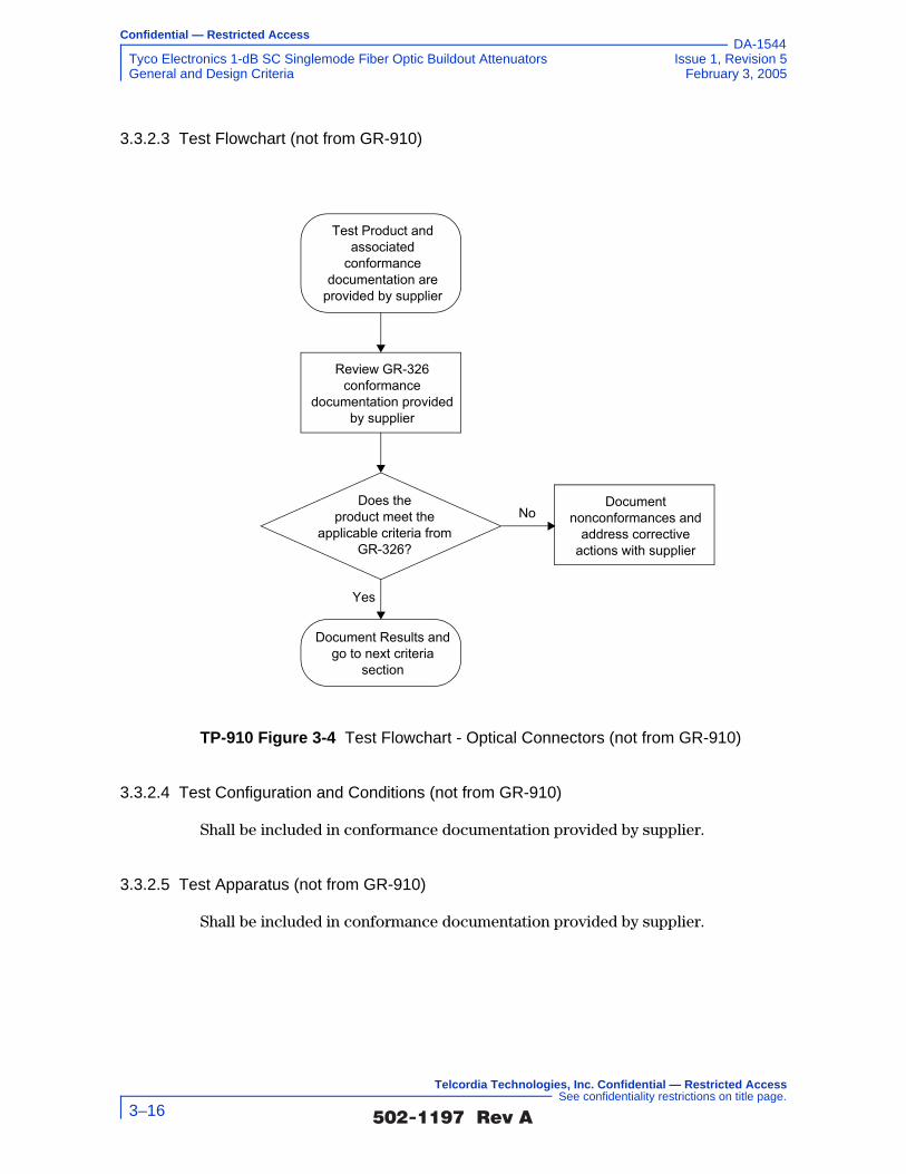
Confidential — Restricted Access
Tyco Electronics 1-dB SC Singlemode Fiber Optic Buildout Attenuators Issue 1, Revision 5General and Design Criteria February 3, 2005
DA-1544
3.3.2.3 Test Flowchart (not from GR-910)
3.3.2.4 Test Configuration and Conditions (not from GR-910)
Shall be included in conformance documentation provided by supplier.
3.3.2.5 Test Apparatus (not from GR-910)
Shall be included in conformance documentation provided by supplier.
TP-910 Figure 3-4 Test Flowchart - Optical Connectors (not from GR-910)
Does theproduct meet the
applicable criteria from GR-326?
Document Results and go to next criteria
section
Document nonconformances and
address corrective actions with supplier
Yes
No
Test Product and associated
conformance documentation are
provided by supplier
Review GR-326 conformance
documentation provided by supplier
�������� �� 3–16
Telcordia Technologies, Inc. Confidential — Restricted Access See confidentiality restrictions on title page.
Confidential — Restricted Access
Issue 1, Revision 5 Tyco Electronics 1-dB SC Singlemode Fiber Optic Buildout AttenuatorsFebruary 3, 2005 General and Design Criteria
DA-1544
3.3.2.6 Summary of Test Results (not from GR-910)
Conformance/Nonconformance
Conformance to the criteria in Section 3.3.2.1 of this document has not been established. Results for requirement GR-910 R3-15 [15] were not determined. Conformance is based on the attenuator’s single-mode optical connectors and/or connector interface used in the construction meeting the criteria in GR-326-CORE.
Failure History
Not applicable.
Disposition of Nonconformance
Not applicable.
Test Data
Not applicable.
3.3.3 Cleanability
3.3.3.1 Criteria - Cleanability (heading not from GR-910)
GR-910 R3-16 [16] Attenuators with accessible attenuation elements shall not be damaged nor change attenuation value when cleaned according to manufacturers’ instructions.
GR-910 R3-17 [17] Suppliers shall specify cleaning instructions and materials for cleaning attenuators.
GR-910 R3-18 [18] Cleaning procedures shall meet all applicable safety requirements.
3.3.3.2 Test Method (not from GR-910)
A. Verify the manufacturer has specified cleaning instructions and cleaning materials for cleaning attenuators.
B. Verify that the manufacturer’s cleaning procedures meet all applicable safety requirements. Also see cleaning safety requirements of Section 3.3.6.
C. Verify that attenuators with accessible attenuation elements are not damaged nor change attenuation value when cleaned according to manufacturers’ instructions.
D. Record test results.
�������� �� 3–17
Telcordia Technologies, Inc. Confidential — Restricted Access See confidentiality restrictions on title page.

Confidential — Restricted Access
Tyco Electronics 1-dB SC Singlemode Fiber Optic Buildout Attenuators Issue 1, Revision 5General and Design Criteria February 3, 2005
DA-1544
E. Any nonconformance shall be documented and reported to the customer authorized representative.
F. If the criteria are met, then subject the DUT to the next test group.
3.3.3.3 Test Flowchart (not from GR-910)
TP-910 Figure 3-5 Test Flowchart - Cleanability (not from GR-910)
Arecleaning procedures
complete and compliant to safety criteria?
Document Results and go to next criteria section
Document nonconformances and
address corrective actions with supplier
Yes
No
Test Product, cleaning instructions, and associated conformance documentation
are provided by supplier
Review cleaning instructions and conformance documentation related to
safety compliance.
Areaccessible attenuation
elements damaged or is attenuation value
changed?
Document nonconformances and
address corrective actions with supplier
No
Yes
Clean attenuators according to manufacture’s instructions.
�������� �� 3–18
Telcordia Technologies, Inc. Confidential — Restricted Access See confidentiality restrictions on title page.

Confidential — Restricted Access
Issue 1, Revision 5 Tyco Electronics 1-dB SC Singlemode Fiber Optic Buildout AttenuatorsFebruary 3, 2005 General and Design Criteria
DA-1544
3.3.3.4 Test Configuration and Conditions (not from GR-910)
Shall be included in the cleaning procedure documentation provided by supplier.
3.3.3.5 Test Apparatus (not from GR-910)
Shall be included in the cleaning procedure documentation provided by supplier.
3.3.3.6 Summary of Test Results (not from GR-910)
Conformance/Nonconformance
Conformance to the criteria in Section 3.3.3.1 of this document has been established. Conformance is based on the verification that the manufacturer has specified cleaning instructions and cleaning materials for cleaning attenuators, verification that the manufacturer’s cleaning procedures meet all applicable safety requirements, and verification that attenuators with accessible attenuation elements are not damaged or that the attenuation value does not change when cleaning.
Failure History
Not applicable.
Disposition of Nonconformance
Not applicable.
Test Data
Not applicable.
Photographs
Not applicable.
3.3.4 Intermateability
Users must be able to purchase attenuators and connectors of a specific design, from a variety of manufacturers, with assurance that the product purchased from one supplier will function satisfactorily when intermated with a product manufactured by another supplier.
Attenuator Intermateability is the ability to integrate different manufacturers’ attenuators and optical connectors, that meet specific performance criteria for attenuator and connector design, even though they may come from different suppliers.
�������� �� 3–19
Telcordia Technologies, Inc. Confidential — Restricted Access See confidentiality restrictions on title page.

Confidential — Restricted Access
Tyco Electronics 1-dB SC Singlemode Fiber Optic Buildout Attenuators Issue 1, Revision 5General and Design Criteria February 3, 2005
DA-1544
3.3.4.1 Criteria - Intermateability (heading not from GR-910)
GR-910 R3-19 [75] Intermateability – Attenuator connectors, connector interfaces, and couplings shall meet the Intermateability requirements describe in GR-326-CORE.
This requirement will help to ensure not only the intermateability of the suppliers’ product to themselves, but also the intermateability of different suppliers’ products to each other.
3.3.4.2 Test Method (not from GR-910)
A. Perform testing or verify conformance of the attenuator to the Intermateability requirements describe in GR-326-CORE, Generic Requirements for Single-
mode Optical Connectors and Jumper Assemblies.
B. Record test results.
C. Any nonconformance shall be documented and reported to the customer authorized representative.
D. If the criteria are met, then subject the DUT to the next test group.
�������� �� 3–20
Telcordia Technologies, Inc. Confidential — Restricted Access See confidentiality restrictions on title page.

Confidential — Restricted Access
Issue 1, Revision 5 Tyco Electronics 1-dB SC Singlemode Fiber Optic Buildout AttenuatorsFebruary 3, 2005 General and Design Criteria
DA-1544
3.3.4.3 Test Flowchart (not from GR-910)
3.3.4.4 Test Configuration and Conditions (not from GR-910)
Shall be included in conformance documentation provided by supplier.
3.3.4.5 Test Apparatus (not from GR-910)
Shall be included in conformance documentation provided by supplier.
3.3.4.6 Summary of Test Results (not from GR-910)
Conformance/Nonconformance
Conformance to the criteria in Section 3.3.4.1 of this document has not been established. Results for requirement GR-910 R3-19 [75] were not determined.
TP-910 Figure 3-6 Test Flowchart - Intermateability (not from GR-910)
Does theproduct meet the
applicable criteria from GR-326?
Document Results and go to next criteria
section
Document nonconformances and
address corrective actions with supplier
Yes
No
Test Product and associated conformance documentation
are provided by supplier
Review GR-326 Intermateability conformance documentation
provided by supplier
�������� �� 3–21
Telcordia Technologies, Inc. Confidential — Restricted Access See confidentiality restrictions on title page.

Confidential — Restricted Access
Tyco Electronics 1-dB SC Singlemode Fiber Optic Buildout Attenuators Issue 1, Revision 5General and Design Criteria February 3, 2005
DA-1544
Conformance is based on the verification that the attenuator connectors, connector interfaces, and couplings meet the Intermateability requirements described in GR-326-CORE.
Failure History
Not applicable.
Disposition of Nonconformance
Not applicable.
Test Data
Not applicable.
3.3.5 Materials
3.3.5.1 Toxicity
GR-910 R3-20 [19] All attenuator materials with which personnel may come in contact shall be non-toxic, and shall not present any environmental hazards as defined by applicable federal or state laws and regulations or current industry standards. Where the suggested use of certain materials by the manufacturer may pose hazardous conditions, the manufacturer shall provide the necessary instructions for the handling and use of such materials.
3.3.5.2 Corrosion Resistance
GR-910 R3-21 [20] Attenuators containing metallic materials shall show no significant signs of corrosion on metallic surfaces or components nor exhibit a malfunction of any mechanical features following a 7- day exposure to a salt fog spray in accordance with ASTM B117. Attenuators shall be placed inside the salt fog chamber during the test. The analysis for the degree of rusting on painted metal surfaces shall be made in accordance with ASTM D610. A rust grade of 9 or better is required, exclusive of any surface scratches or nicks noted prior to testing.
3.3.5.3 Dissimilar Metals
GR-910 R3-22 [21] The attenuator design shall ensure that no galvanic corrosion will occur when dissimilar metals are used in its construction.
�������� �� 3–22
Telcordia Technologies, Inc. Confidential — Restricted Access See confidentiality restrictions on title page.

Confidential — Restricted Access
Issue 1, Revision 5 Tyco Electronics 1-dB SC Singlemode Fiber Optic Buildout AttenuatorsFebruary 3, 2005 General and Design Criteria
DA-1544
3.3.5.4 Fungus Resistance
GR-910 R3-23 [22] Exposed polymeric materials used in the attenuator design shall not support fungus growth per ASTM-G21. A rating of zero (0) is required.
3.3.5.5 Flammability
These flammability requirements apply to attenuators that are intended to be located inside buildings.
GR-910 R3-24 [23] Exposed plastic materials shall have an oxygen index of at least 28% as determined by actual test in accordance with ASTM D-2863 and GR-63-CORE, Section 4.2.3, Use of Fire-Resistant Materials, Components, Wiring and Cable.
GR-910 R3-25 [24] Exposed plastic materials shall not sustain combustion when an open flame source is removed, such that they possess a rating of 94V-1 when tested according to the Vertical Burning Test for Classifying Material, Underwriters Laboratories publication UL94, Tests for Flammability of Plastic Materials for
Parts in Devices and Appliances, or GR-63-CORE, Section 5.2.4, Telcordia Needle
Flame Test. Manufacturers may be requested to provide material samples of appropriate size for testing.
“Exposed plastic materials” refers to the exterior of the final attenuator packaging that would be used for indoor applications.
3.3.5.6 Test Method (not from GR-910)
A. Verify the manufacturer has provided all documentation on all attenuator materials with which personnel may come in contact are non-toxic, and do not present any environmental hazards as defined by applicable federal or state laws and regulations or current industry standards. Where the suggested use of certain materials by the manufacturer may pose hazardous conditions, the manufacturer shall provide the necessary instructions for the handling and use of such materials.
B. Verify that attenuators containing metallic materials show no significant signs of corrosion on metallic surfaces or components nor exhibit a malfunction of any mechanical features following a 7-day exposure to a salt fog spray in accordance with ASTM B117. Attenuators shall be placed inside the salt fog chamber during the test. The analysis for the degree of rusting on painted metal surfaces shall be made in accordance with ASTM D610. A rust grade of 9 or better is required, exclusive of any surface scratches or nicks noted prior to testing.
�������� �� 3–23
Telcordia Technologies, Inc. Confidential — Restricted Access See confidentiality restrictions on title page.

Confidential — Restricted Access
Tyco Electronics 1-dB SC Singlemode Fiber Optic Buildout Attenuators Issue 1, Revision 5General and Design Criteria February 3, 2005
DA-1544
C. Verify that the attenuator design ensures that no galvanic corrosion will occur when dissimilar metals are used in its construction.
D. Verify that exposed polymeric materials used in the attenuator design do not support fungus growth per ASTM-G21. A rating of zero (0) is required.
E. Verify that exposed plastic materials have an oxygen index of at least 28% as determined by actual test in accordance with ASTM D-2863 and GR-63-CORE, Section 4.2.3, Use of Fire-Resistant Materials, Components, Wiring, and
Cable.
F. Verify that exposed plastic materials do not sustain combustion when an open flame source is removed, such that they possess a rating of 94V-l when tested according to the Vertical Burning Test for Classifying Material, Underwriters Laboratories publication UL94, Tests for Flammability of Plastic Materials for
Parts in Devices and Appliances, or GR-63-CORE, Section 5.2.4, Telcordia
Needle Flame Test. Manufacturers may be requested to provide material samples of appropriate size for testing.
�������� �� 3–24
Telcordia Technologies, Inc. Confidential — Restricted Access See confidentiality restrictions on title page.

Confidential — Restricted Access
Issue 1, Revision 5 Tyco Electronics 1-dB SC Singlemode Fiber Optic Buildout AttenuatorsFebruary 3, 2005 General and Design Criteria
DA-1544
3.3.5.7 Test Flowchart (not from GR-910)
3.3.5.8 Test Configuration and Conditions (not from GR-910)
Not applicable
3.3.5.9 Test Apparatus (not from GR-910)
Not applicable
TP-910 Figure 3-7 Test Flowchart - Materials (not from GR-910)
Does theproduct meet the
applicable toxicity, corrosion, fungus and flammability
criteria?
Document Results and go to next criteria
section
Document nonconformances and
address corrective actions with supplier
Yes
No
Test Product and associated conformance documentation
are provided by supplier
Review conformance documentation related to
toxicity, corrosion, fungus and flammability
�������� �� 3–25
Telcordia Technologies, Inc. Confidential — Restricted Access See confidentiality restrictions on title page.

Confidential — Restricted Access
Tyco Electronics 1-dB SC Singlemode Fiber Optic Buildout Attenuators Issue 1, Revision 5General and Design Criteria February 3, 2005
DA-1544
3.3.5.10 Summary of Test Results (not from GR-910)
Conformance/Nonconformance
Conformance to the criteria in Section 3.3.5.1 has been completely established. Conformance to the criteria in Section 3.3.5.2, Section 3.3.5.3, Section 3.3.5.4, and Section 3.3.5.5 of this document has not been established. Results for requirements GR-910 R3-21 [20], GR-910 R3-22 [21], GR-910 R3-23 [22], GR-910 R3-24 [23] and GR-910 R3-25 [24] were not determined. Conformance is based on the verification that the manufacturer has provided all documentation on all attenuator materials indicating the materials personnel may come in contact with are non-toxic and do not present any environmental hazards as defined by applicable federal or state laws and regulations or current industry standards. If the suggested use of certain materials by the manufacturer poses hazardous conditions, the necessary instructions for the handling and use of such materials are provided. Conformance is also based on the verification that attenuators containing metallic materials show no significant signs of corrosion on metallic surfaces or components nor exhibit a malfunction of any mechanical features following a 7-day exposure to a salt fog spray in accordance with ASTM B117, and that the degree of rusting on painted metal surfaces, in accordance with ASTM D610, meet a rust grade of 9 or better, exclusive of any surface scratches or nicks noted prior to testing. Conformance is also based on the verification that the attenuator design shows no galvanic corrosion when dissimilar metals are used in its construction, verification that fungus growth on exposed polymeric materials used in the attenuator design does not exceed a rating of zero (0) as per ASTM-G21, verification that exposed plastic materials have an oxygen index of at least 28% as determined by actual testing in accordance with ASTM D-2863 and GR-63-CORE, Section 4.2.3, and verification that exposed plastic materials do not sustain combustion when an open flame source is removed and posses a rating of 94V-1 when tested according to the vertical Burning Test for Classifying Material, Underwriters Laboratories publication UL94 or GR-63-CORE, Section 5.2.4.
Failure History
Not applicable.
Disposition of Nonconformance
Not applicable.
Test Data
Not applicable.
�������� �� 3–26
Telcordia Technologies, Inc. Confidential — Restricted Access See confidentiality restrictions on title page.

Confidential — Restricted Access
Issue 1, Revision 5 Tyco Electronics 1-dB SC Singlemode Fiber Optic Buildout AttenuatorsFebruary 3, 2005 General and Design Criteria
DA-1544
3.3.6 Safety
3.3.6.1 Criteria - Safety (heading not from GR-910)
GR-910 R3-26 [25] The supplier shall provide written warning of precautions for use of the product.
GR-910 R3-27 [76] Radiation Hazard – The instructions that describe the procedures for cleaning attenuators shall indicate the possible hazard due to the presence of invisible (infrared) radiation when examining connectors with the naked eye or using a microscope. The instruction shall also contain ordering information for an IR indicator card (Edmund Scientific part #53-031 or equivalent) to allow visualization of invisible IR light.
GR-910 R3-28 [77] Cleaning Materials – The instructions that describe the procedures for cleaning the attenuators shall contain the following information regarding any materials that are used for cleaning that may be considered hazardous to health or to the environment:
1. Warning as to the toxicity hazard
2. Instructions for handling and use
3. Instructions for disposal.
3.3.6.2 Test Method (not from GR-910)
A. Verify the supplier has provided written warning of precautions for use of the product.
B. Verify that the attenuator cleaning instructions describe procedures for indicating possible hazard due to the presence of invisible (infrared) radiation when examining connectors with the naked eye or using a microscope. Also verify that the instruction contain ordering information for an IR indicator card (Edmund Scientific part #53-031or equivalent).
C. Verify that attenuator cleaning instructions contain the following information regarding any materials that are used for cleaning that may be considered hazardous to health or to the environment: (1) Warning as to the toxicity hazard, (2) Instructions for handling and use, and (3) Instructions for disposal.
D. Record test results.
E. Any nonconformance shall be documented and reported to the customer authorized representative.
F. If the criteria are met, then subject the DUT to the next test group.
�������� �� 3–27
Telcordia Technologies, Inc. Confidential — Restricted Access See confidentiality restrictions on title page.

Confidential — Restricted Access
Tyco Electronics 1-dB SC Singlemode Fiber Optic Buildout Attenuators Issue 1, Revision 5General and Design Criteria February 3, 2005
DA-1544
3.3.6.3 Test Flowchart (not from GR-910)
TP-910 Figure 3-8 Test Flowchart - Safety (not from GR-910)
Arewritten warning of
precautions for use of the product provided?
Document Results and go to next criteria section
Document nonconformances and
address corrective actions with supplier
Yes
No
Test Product, cleaning instructions, and precaution documentation are
provided by supplier
Review cleaning instructions and conformance documentation related to safety compliance.
Arethe safety instructions
and warnings specified in GR-910 R3-27 [76] and
GR-910 R3-28 [77] provided?
Document nonconformances and
address corrective actions with supplier
Yes
No
Review the instructions that describe the procedures for cleaning the attenuator. Clean
attenuators according to manufacture’s instructions.
�������� �� 3–28
Telcordia Technologies, Inc. Confidential — Restricted Access See confidentiality restrictions on title page.
Confidential — Restricted Access
Issue 1, Revision 5 Tyco Electronics 1-dB SC Singlemode Fiber Optic Buildout AttenuatorsFebruary 3, 2005 General and Design Criteria
DA-1544
3.3.6.4 Test Configuration and Conditions (not from GR-910)
Not applicable
3.3.6.5 Test Apparatus (not from GR-910)
Not applicable
3.3.6.6 Summary of Test Results (not from GR-910)
Conformance/Nonconformance
Conformance to the criteria in Section 3.3.6.1 of this document has been partially established. Results for requirement GR-910 R3-26 [25] and GR-910 R3-27 [76] were not determined. Conformance is based on the verification that the supplier has provided written warning of precautions for use of the product, verification that the attenuator cleaning instructions describe procedures for indicating possible hazard due to the presence of invisible (infrared) radiation when examining connectors with the naked eye or using a microscope and that the instructions contain ordering information for an IR indicator card, and verification that the attenuator cleaning instructions contain the information outlined in GR-910 R3-28 [77] regarding any materials that are used for cleaning that may be considered hazardous to health or to the environment.
Failure History
Not applicable.
Disposition of Nonconformance
Not applicable.
Test Data
Not applicable.
3.3.7 Mounting
Depending on the application and on specific Telcordia client practices, attenuators may be located in Central Offices and in various locations in the Outside Plant, including the underground, buried and aerial plant.2
2. Attenuators may also be located in an Alternate Splice Area (ASA), also referred to as an Optical Cable Rearrangement Facility (OCRF), a splice area within the CO that is not within the Cable Entrance Facility. For more information, see Section 2.5.2 of BR 781-826-127, Optical Cross-Connect Planning.
�������� �� 3–29
Telcordia Technologies, Inc. Confidential — Restricted Access See confidentiality restrictions on title page.

Confidential — Restricted Access
Tyco Electronics 1-dB SC Singlemode Fiber Optic Buildout Attenuators Issue 1, Revision 5General and Design Criteria February 3, 2005
DA-1544
3.3.7.1 Criteria - Mounting (heading not from GR-910)
GR-910 R3-29 [26] Fiber optic attenuators shall be provided with a means to be installed in Central Offices and Remote Sites.
GR-910 O3-30 [27] Attenuators should be capable of being mounted on standard 23-inch relay racks, cabinets, pedestals, splice trays, splice organizers and splice closures or other protective enclosures.
GR-910 R3-31 [28] Variable attenuators shall be mounted in such a way that the adjustment mechanism is easily recognizable and accessible to craft personnel.
The location of the attenuator is important because it determines how accessible the attenuators will be to craftpersons for testing, repair and growth of future services. Attenuators terminated in connectors can be mounted in racks and cabinets, and are more accessible than attenuators mounted in OSP closures, which are usually spliced.
Outside Plant Location
GR-910 R3-32 [29] Attenuators deployed in an uncontrolled environment shall have a protective enclosure to restrict water intrusion into the attenuator housing package.
GR-910 R3-33 [30] Installed attenuators shall be easily accessible for operations and maintenance support.
3.3.7.2 Test Method (not from GR-910)
A. Perform visual inspection on the mounting of the attenuator to determine the following:
1. Verify that the attenuator provides a means to be installed in Central Offices and Remote Sites.
2. Determine if the attenuator is capable of being mounted on standard 23-inch relay racks, cabinets, pedestals, splice trays, splice organizers and splice closures or other protective enclosures.
3. Verify that variable attenuators can be mounted in such a way that the adjustment mechanism is easily recognizable and accessible to craft personnel.
�������� �� 3–30
Telcordia Technologies, Inc. Confidential — Restricted Access See confidentiality restrictions on title page.

Confidential — Restricted Access
Issue 1, Revision 5 Tyco Electronics 1-dB SC Singlemode Fiber Optic Buildout AttenuatorsFebruary 3, 2005 General and Design Criteria
DA-1544
4. Verify that attenuators intended for deployment in an uncontrolled environment have a protective enclosure to restrict water intrusion into the attenuator package.
5. Verify that the installed attenuator can be easily accessible for operations and maintenance support.
B. Record test results.
C. Any nonconformance shall be documented and reported to the customer authorized representative in accordance with the Quality Assurance Program of Telcordia. A determination shall be made regarding possible employment of hot spares or if the testing is to be continued.
D. If the criteria are met, then subject the DUT to the next test group.
3.3.7.3 Test Flowchart (not from GR-910)
TP-910 Figure 3-9 Test Flowchart - Mounting (not from GR-910)
Does theproduct meet the
applicable criteria from Section 3.3.7.1?
Document Results and go to next criteria
section
Document nonconformances and
address corrective actions with supplier
Yes
No
Test Product and associated installation
documentation are provided by supplier
Visually inspect mounting capabilities and review
installation documentation
�������� �� 3–31
Telcordia Technologies, Inc. Confidential — Restricted Access See confidentiality restrictions on title page.
Confidential — Restricted Access
Tyco Electronics 1-dB SC Singlemode Fiber Optic Buildout Attenuators Issue 1, Revision 5General and Design Criteria February 3, 2005
DA-1544
3.3.7.4 Test Configuration and Conditions (not from GR-910)
Not applicable
3.3.7.5 Test Apparatus (not from GR-910)
Not applicable
3.3.7.6 Summary of Test Results (not from GR-910)
Conformance/Nonconformance
Conformance to the criteria in Section 3.3.7.1 of this document has been partially established. The criteria for requirements GR-910 R3-31 [28] and Verizon’s Requirement were not applicable, and results for requirement GR-910 R3-32 [29] were not determined. Conformance is based on the verification that the attenuator provides a means to be installed in Central Offices and Remote Sites and that the attenuator is capable of being mounted on standard 23-inch relay racks, cabinets, pedestals, splice trays, splice organizers and splice closures or other protective enclosures. Conformance is also based on the verification that attenuators intended for deployment in an uncontrolled environment have a protective enclosure to restrict water intrusion into the attenuator package, and verification that the installed attenuator can be easily accessible for operations and maintenance support.
Failure History
Not applicable.
Disposition of Nonconformance
Not applicable.
Test Data
Not applicable.
Sample Size
Not applicable
Photographs
Not applicable
�������� �� 3–32
Telcordia Technologies, Inc. Confidential — Restricted Access See confidentiality restrictions on title page.

Confidential — Restricted Access
Issue 1, Revision 5 Tyco Electronics 1-dB SC Singlemode Fiber Optic Buildout AttenuatorsFebruary 3, 2005 General and Design Criteria
DA-1544
3.3.8 Index Matching
3.3.8.1 Criteria - Index Matching (heading not from GR-910)
GR-910 R3-34 [31] Application of index-matching materials shall not be required for use of the attenuator.
3.3.8.2 Test Method (not from GR-910)
A. Examine the attenuator and the supplier documentation to verify that the application of index-matching materials is not required for use of the attenuator.
B. Record test results.
C. Any nonconformance shall be documented and reported to the customer authorized representative in accordance with the Quality Assurance Program of Telcordia. A determination shall be made regarding possible employment of hot spares or if the testing is to be continued.
D. If the criteria are met, then subject the DUT to the next test group.
�������� �� 3–33
Telcordia Technologies, Inc. Confidential — Restricted Access See confidentiality restrictions on title page.

Confidential — Restricted Access
Tyco Electronics 1-dB SC Singlemode Fiber Optic Buildout Attenuators Issue 1, Revision 5General and Design Criteria February 3, 2005
DA-1544
3.3.8.3 Test Flowchart (not from GR-910)
3.3.8.4 Test Configuration and Conditions (not from GR-910)
Not applicable
3.3.8.5 Test Apparatus (not from GR-910)
Not applicable
TP-910 Figure 3-10 Test Flowchart - Index Matching (not from GR-910)
Does theproduct require the application of index-matching materials?
Document Results and go to next criteria
section
Document nonconformances and
address corrective actions with supplier
No
Yes
Test Product and associated installation
documentation are provided by supplier
Visually inspect attenuator and review
installation documentation
�������� �� 3–34
Telcordia Technologies, Inc. Confidential — Restricted Access See confidentiality restrictions on title page.

Confidential — Restricted Access
Issue 1, Revision 5 Tyco Electronics 1-dB SC Singlemode Fiber Optic Buildout AttenuatorsFebruary 3, 2005 General and Design Criteria
DA-1544
3.3.8.6 Summary of Test Results (not from GR-910)
Conformance/Nonconformance
Conformance to the criteria in Section 3.3.8.1 of this document has been established. Conformance is based on the verification that the attenuator and the supplier documentation does not require the application of index-matching materials for use of the attenuator.
Failure History
Not applicable.
Disposition of Nonconformance
Not applicable.
Test Data
Not applicable.
3.3.9 Change of Attenuation
3.3.9.1 Criteria - Change of Attenuation (heading not from GR-910)
To change the attenuation of a variable attenuator or remove and replace fixed attenuators in an optical transmission system:
GR-910 CR3-35 [32] It shall be possible to vary the attenuation of a variable attenuator after it is installed in a transmission system.
GR-910 R3-36 [33] It shall not be necessary to access both sides of the distributing frame, nor remove screws or other mounting hardware.
GR-910 R3-37 [34] It shall not be necessary to re-splice fibers for attenuators other than those designed to be spliced to a fiber.
3.3.9.2 Test Method (not from GR-910)
A. Verify the following:
1. The attenuation of a variable attenuator can be changed after it is installed in a transmission system.
2. To change the attenuation of a variable attenuator or remove and replace fixed attenuators in an optical transmission system it is not necessary to access both sides of the distributing frame, nor remove screws or other mounting hardware.
�������� �� 3–35
Telcordia Technologies, Inc. Confidential — Restricted Access See confidentiality restrictions on title page.

Confidential — Restricted Access
Tyco Electronics 1-dB SC Singlemode Fiber Optic Buildout Attenuators Issue 1, Revision 5General and Design Criteria February 3, 2005
DA-1544
3. It is not necessary to re-splice fibers for attenuators (other than those designed to be spliced to a fiber) to change the attenuation of a variable attenuator or remove and replace fixed attenuators in an optical transmission system.
B. Record test results.
C. Any nonconformance shall be documented and reported to the customer authorized representative in accordance with the Quality Assurance Program of Telcordia. A determination shall be made regarding possible employment of hot spares or if the testing is to be continued.
D. If the criteria are met, then subject the DUT to the next test group.
�������� �� 3–36
Telcordia Technologies, Inc. Confidential — Restricted Access See confidentiality restrictions on title page.

Confidential — Restricted Access
Issue 1, Revision 5 Tyco Electronics 1-dB SC Singlemode Fiber Optic Buildout AttenuatorsFebruary 3, 2005 General and Design Criteria
DA-1544
3.3.9.3 Test Flowchart (not from GR-910)
TP-910 Figure 3-11 Test Flowchart - Change in Attenuation (not from GR-910)
Can variable attenuator be changed after it
is installed?
Document Results and go to next criteria section
Document nonconformances and
address corrective actions with supplier
Yes
No
Test Product and application documentation are provided by
supplier
Examine the attenuator and review application instructions for
changing attenuation.
Arethe change of
attenuation criteria in R3-36 and R3-37 met?
Document nonconformances and
address corrective actions with supplier
Yes
No
Examine the attenuator and review application instructions for
changing attenuation.
�������� �� 3–37
Telcordia Technologies, Inc. Confidential — Restricted Access See confidentiality restrictions on title page.

Confidential — Restricted Access
Tyco Electronics 1-dB SC Singlemode Fiber Optic Buildout Attenuators Issue 1, Revision 5General and Design Criteria February 3, 2005
DA-1544
3.3.9.4 Test Configuration and Conditions (not from GR-910)
Not applicable
3.3.9.5 Test Apparatus (not from GR-910)
Not applicable
3.3.9.6 Summary of Test Results (not from GR-910)
Conformance/Nonconformance
Conformance to the criteria in Section 3.3.9.1 of this document has been partially established. Results for requirement GR-910 CR3-35 [32] were not applicable. Conformance is based on the verification that it is not necessary to access both sides of the distributing frame, nor remove screws or other mounting hardware when removing and replacing fixed attenuators in an optical transmission system, and verification that it is not necessary to re-splice fibers for attenuators other than those designed to be spliced to a fiber when removing and replacing fixed attenuators in an optical transmission system.
Failure History
Not applicable.
Disposition of Nonconformance
Not applicable.
Test Data
Not applicable.
Sample Size
Not applicable.
Photographs
Not applicable.
�������� �� 3–38
Telcordia Technologies, Inc. Confidential — Restricted Access See confidentiality restrictions on title page.

Confidential — Restricted Access
Issue 1, Revision 5 Tyco Electronics 1-dB SC Singlemode Fiber Optic Buildout AttenuatorsFebruary 3, 2005 Performance Criteria
DA-1544
4.0 Performance Criteria
For the definition of requirements, objectives, and conditional requirements, see the “Requirements Terminology:” section in the Executive Summary. The criteria fall into two categories: Optical Criteria that address unstressed, optical performance characteristics and Environmental and Mechanical Criteria that address compliance with the change in attenuation requirements, ∆A, for either analog transmission, digital transmission, or both, whichever applies, when attenuators are subjected to stress. The change in attenuation criteria in Section 4.2.2 must be met after (and in some cases during) each individual stress test in Section 4.1.
GR-910 Table 4-1 summarizes attenuator performance Requirements and Objectives. The criteria appear in the chronological order intended for testing and in the order of their appearance in this document. Compliance with all criteria is verified according to the test procedures in Section 5. The Optical Criteria are
verified only after the Environmental and Mechanical Tests.
GR-910 Table 4-1 Summary of Attenuator Performance Criteria and Test Sequence
CHARACTERISTIC SECT. CRITERIA
Environmental & Mechanical 4.1 Conditions
Controlled Operating Environment 4.1.1 –5°C to 50°C, 5 to 95% RH
Uncontrolled Operating Environment 4.1.2 –40°C to 75°C, RH 0 to 90% ±5%
Non-operating Environment 4.1.3 –40°C to 70°C, 0 to 95% RH
Humidity/Condensation Cycling Test 4.1.4 –10°C to 65°C, ≥ 90% RH
Water Immersion 4.1.5 43°C, PH 5.5, 7 days
Vibration 4.1.6 10 - 55 Hz, 1.52 mm amplitude, for 2 hrs
Flex Test 4.1.7 0.5, or 2 lb load, 100 cycles
Twist Test 4.1.8 1.1, 1.65 lb, or 3 lb load, 10 cycles
Side Pull 4.1.9 0.55 or 2.75 lb load, 90°angle, active
Cable Retention 4.1.10 1 lb, 1.54 lb, or 4.4 lb load, for 1 min.
Durability 4.1.11 200 cyc., 3 ft, 4.5 ft, 6 ft per GR-326
Impact Test 4.1.12 6 ft. drop, 8 cycles, 3 axes
Optical Criteria 4.2 Digital (CR) AM-Video (CR)
Optical Bandpass (nm) 4.2.1 1260 –>1360 1290 –>1330
" & 1480 –>1580# & (1530 –>1570)†
Change in Attenuation ∆A (dB) 4.2.2 ±0.5 or 0.15A ±0.5 or 0.10A
Attenuation Tolerance (dB) 4.2.3 ±0.15V ±0.10V
Attenuation Increments and Range (dB) 4.2.4 ≥ 5 dB, ≥ 5 to 20 dB
≥ 3 dB, ≥ 3 to 20 dB@
�������� �� 4–1
Telcordia Technologies, Inc. Confidential — Restricted Access See confidentiality restrictions on title page.

Confidential — Restricted Access
Tyco Electronics 1-dB SC Singlemode Fiber Optic Buildout Attenuators Issue 1, Revision 5Performance Criteria February 3, 2005
DA-1544
Notes:
# The conditional objective for digital applications in the upper window is 1430 to 1580nm.
†The conditional requirement for LR-SONET applications is 1280 to 1335 and 1525 to 1575nm. See Section 4.2.1 for more on LR-SONET.
@ The increment conditional objective for attenuators used in AM video applications is ≥ 1 dB. The range objective for attenuators in all applications is ≥ 1 to 25 dB.
4.1 Environmental and Mechanical Criteria
The change in attenuation and reflectance criteria in GR-910 Table 4-1 are used as the pass/fail criteria for environmental and mechanical tests, in which attenuators are subjected to thermal, water-related and mechanical stress. Mechanical stress in attenuators can physically damage attenuators, attenuation elements, optical interfaces, and adjustment mechanisms in variable attenuators, thereby degrading product performance. Elevated temperature and humidity may degrade the performance of adhesives, attenuating fibers, and attenuating elements used to manufacture attenuators.
The thermal and water-related tests are also intended to indicate the performance of attenuators exposed to short-term freezing, heat, high humidity and water immersion, as may exist in a controlled CO, CEV, or uncontrolled loop plant environment. The other tests are intended to ensure the mechanical integrity and ruggedness of attenuators. The Vibration, Cable Retention, Side Pull, and Impact Tests apply to all attenuators. The Flex and Twist tests apply only to attenuators with optical fiber leads and are intended to stress the attenuator-to-fiber interface. The Durability Test applies to variable attenuators and attenuators with connectors or connector interfaces that are an integral part of the attenuation mechanism. Refer to GR-910 R4-37 [73] for a description of what constitutes physical damage.
Tensile loads for the mechanical tests are shown in GR-910 Table 4-2. The applied load depends on the attenuators media type.
Environmental Requirements and Objectives refer to the reflectance, and change in attenuation, ∆A, before, during, and after attenuators are subjected to the Temperature and Humidity Criteria described in Section 4.1 of GR-63-CORE. Mechanical requirements and objectives refer to the reflectance and change in
Reflectance (dB) 4.2.5 –40 –55 (–65)
PDL (dB) 4.2.6 ±0.5 or 0.15A ±0.5 or 0.10A
PMD (dB) 4.2.7 0.2 ps
GR-910 Table 4-1 Summary of Attenuator Performance Criteria and Test Sequence (Continued)
CHARACTERISTIC SECT. CRITERIA
�������� �� 4–2
Telcordia Technologies, Inc. Confidential — Restricted Access See confidentiality restrictions on title page.
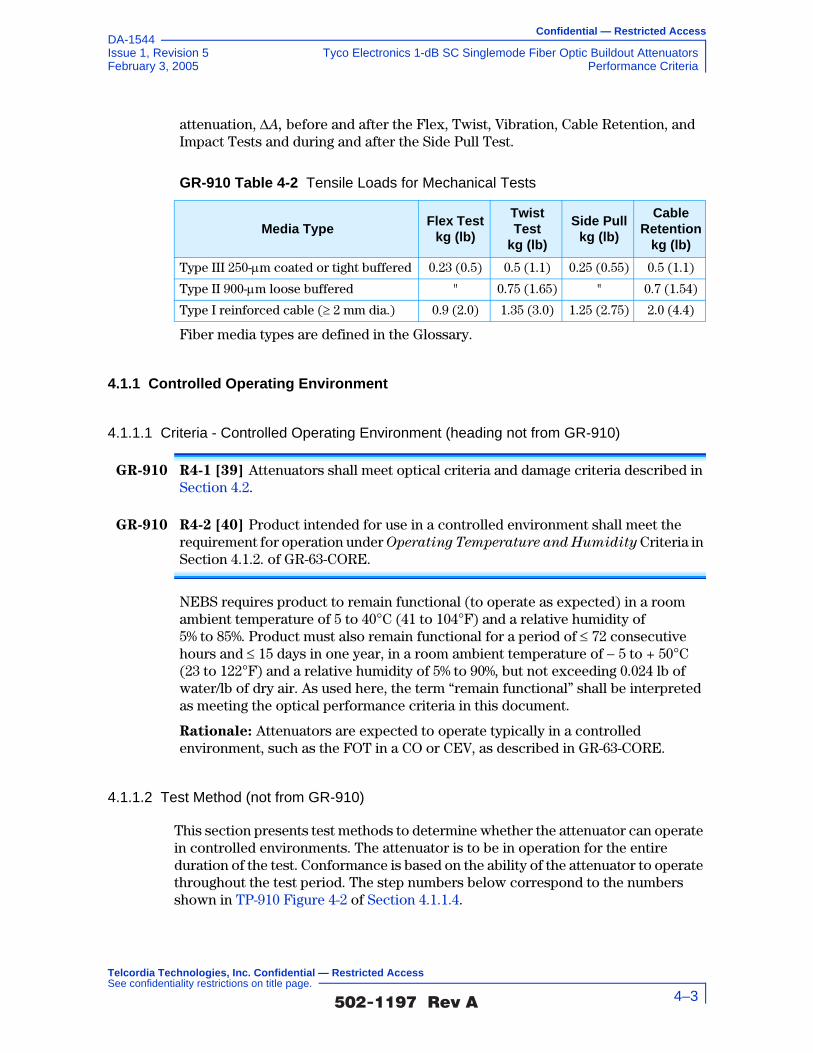
Confidential — Restricted Access
Issue 1, Revision 5 Tyco Electronics 1-dB SC Singlemode Fiber Optic Buildout AttenuatorsFebruary 3, 2005 Performance Criteria
DA-1544
attenuation, ∆A, before and after the Flex, Twist, Vibration, Cable Retention, and Impact Tests and during and after the Side Pull Test.
Fiber media types are defined in the Glossary.
4.1.1 Controlled Operating Environment
4.1.1.1 Criteria - Controlled Operating Environment (heading not from GR-910)
GR-910 R4-1 [39] Attenuators shall meet optical criteria and damage criteria described in Section 4.2.
GR-910 R4-2 [40] Product intended for use in a controlled environment shall meet the requirement for operation under Operating Temperature and Humidity Criteria in Section 4.1.2. of GR-63-CORE.
NEBS requires product to remain functional (to operate as expected) in a room ambient temperature of 5 to 40°C (41 to 104°F) and a relative humidity of 5% to 85%. Product must also remain functional for a period of ≤ 72 consecutive hours and ≤ 15 days in one year, in a room ambient temperature of − 5 to + 50°C (23 to 122°F) and a relative humidity of 5% to 90%, but not exceeding 0.024 lb of water/lb of dry air. As used here, the term “remain functional” shall be interpreted as meeting the optical performance criteria in this document.
Rationale: Attenuators are expected to operate typically in a controlled environment, such as the FOT in a CO or CEV, as described in GR-63-CORE.
4.1.1.2 Test Method (not from GR-910)
This section presents test methods to determine whether the attenuator can operate in controlled environments. The attenuator is to be in operation for the entire duration of the test. Conformance is based on the ability of the attenuator to operate throughout the test period. The step numbers below correspond to the numbers shown in TP-910 Figure 4-2 of Section 4.1.1.4.
GR-910 Table 4-2 Tensile Loads for Mechanical Tests
Media TypeFlex Test
kg (lb)
Twist Test
kg (lb)
Side Pullkg (lb)
Cable Retention
kg (lb)
Type III 250-µm coated or tight buffered 0.23 (0.5) 0.5 (1.1) 0.25 (0.55) 0.5 (1.1)
Type II 900-µm loose buffered " 0.75 (1.65) " 0.7 (1.54)
Type I reinforced cable (≥ 2 mm dia.) 0.9 (2.0) 1.35 (3.0) 1.25 (2.75) 2.0 (4.4)
�������� �� 4–3
Telcordia Technologies, Inc. Confidential — Restricted Access See confidentiality restrictions on title page.

Confidential — Restricted Access
Tyco Electronics 1-dB SC Singlemode Fiber Optic Buildout Attenuators Issue 1, Revision 5Performance Criteria February 3, 2005
DA-1544
Test Sequence - Monitor the chamber's temperature continuously during the test. Verify lab ambient conditions, calibration and appropriate setup of product under test. Inspect product physical conditions and perform initial optical measurements. Optical measurements shall be made throughout the thermal cycle.
1. Operate the attenuator at an ambient temperature of 23°C (73°F) and RH level of 50% for a minimum period of 24 hrs.
2. Decrease the chamber's temperature at a rate of 30°C/ hr (54°F/hr) to –5°C (23°F). RH is not controlled.
3. Maintain a temperature of –5°C (23°F) and any RH for 16 hrs.
4. Increase the chamber's temperature at a rate of 5°C/hr (9°F/hr) to 5°C (41°F). RH is not controlled.
5. Increase the chamber's temperature at a rate of 5°C/hr (9°F/hr) to 28°C (82°F). Increase the RH to attain a 90% level by the time the target temperature is attained.
6. Maintain a temperature of 28°C (82°F) and RH of 90% for 96 hrs.
7. Increase the chamber's temperature at a rate of 5°C/hr (9°F/hr) to 50°C1 (122°F). Decrease the RH to less than 32% (by the time the target temperature is attained).
8. Maintain a temperature of 50°C* (122°F) and less than 32% RH for 12 hrs.
9. Maintain a temperature of 50°C* (122°F) for an additional 4 hrs. During these 4 hrs, reduce the RH to less than 15%.
10. Decrease the chamber's temperature at a rate of about 5°C/hr (9°F/hr) to 5°C (41°F) and maintain the RH to less than 15%.
11. Maintain a temperature of 5°C (41°F) and a RH of less than 15% for 3 hrs.
12. Increase the chamber's temperature at a rate of 30°C/hr (54°F/hr) to 50°C (122°F). RH is not controlled.
13. Maintain a temperature of 50°C (122°F) and any RH for 3 hrs.
14. Decrease the chamber's temperature at a rate of 30°C/hr (54°F/hr) to 23°C (73°F). RH is not controlled.
15. Perform final optical measurements, inspect physical damage and record results.
1. The 50°C temperature is applied to frame-level equipment. For shelves (equipment that occupy less than half a frame), a temperature of 55°C (131°F) and 25% RH shall be used.
�������� �� 4–4
Telcordia Technologies, Inc. Confidential — Restricted Access See confidentiality restrictions on title page.

Confidential — Restricted Access
Issue 1, Revision 5 Tyco Electronics 1-dB SC Singlemode Fiber Optic Buildout AttenuatorsFebruary 3, 2005 Performance Criteria
DA-1544
4.1.1.3 Test Flowchart (not from GR-910)
TP-910 Figure 4-1 Test Flowchart - Controlled Operating Environment Test (not from GR-910)
Were thecomponents
undamaged and the optical measurements
within specs?
Document Results and go to next criteria
section
Yes
No
Clean connection points and perform initial optical
measurements
Prepare/warm-up test equipment per manufacturers’
instructions
Verify test equipment calibration
Verify lab ambient conditions of 23 ±5°C
and 30 to 70% RH
Verify product under test is configured per
supplier’s instructions
Inspect physical condition of product
under test
Stabilize product under test at room temperature with less than 50% RH
for 2 hours
Place all components in environmental chamber
Perform final optical measurements and
inspect for any physical damage
Stabilize components at room temperature for
2 hours
Document nonconformances and
address corrective actions with supplier
Run chamber control program and execute (and record results of)
daily optical measurements at
specified temperatures
Program environmental chamber to perform
temperature and humidity profile shown in
TP-910 Figure 4-2
�������� �� 4–5
Telcordia Technologies, Inc. Confidential — Restricted Access See confidentiality restrictions on title page.

Confidential — Restricted Access
Tyco Electronics 1-dB SC Singlemode Fiber Optic Buildout Attenuators Issue 1, Revision 5Performance Criteria February 3, 2005
DA-1544
4.1.1.4 Test Configuration and Conditions (not from GR-910)
TP-910 Figure 4-2 Operating Temperature and Humidity Test
Tem
pera
ture
°C
Time - Hours
* 55°C, 25% RH for shelves that fill less than 50% the frame length.
6
50
40
30
20
10
0
24 72 120 168 216
14
12
11
10
1398
7
5
1
2
4
3
1. Dwell, 23°C, 50% RH, (24 hrs)
2. Transition, 30°C/hr, any RH (1 hr)
3. Dwell, –5°C, any RH (16 hrs)
4. Transition to +5°C, any RH, 5°C/hr (2 hrs)
5. Transition to 28°C and 90% RH, 5°C/hr (4.6 hrs)
6. Dwell, 28°C, 90% RH (96 hrs)
7. Transition to (50°C*, 32%* RH), 5°C/ hr (5.4 hrs)
8. Dwell, 50°C*, 32% RH (12 hrs)
9. Dwell, 50°C*, 15% RH (4 hrs)
10. Transition to +5°C, <15% RH, 5°C/hr (9 hrs)
11. Dwell, 5°C, <15% RH (3 hrs)
12. Transition to 50°C, 30°C/hr, any RH (1.5 hrs)
13. Dwell, 50°C, any RH (3 hrs)
14. Transition to 23°C, 30°C/hr, any RH (1hr)
�������� �� 4–6
Telcordia Technologies, Inc. Confidential — Restricted Access See confidentiality restrictions on title page.

Confidential — Restricted Access
Issue 1, Revision 5 Tyco Electronics 1-dB SC Singlemode Fiber Optic Buildout AttenuatorsFebruary 3, 2005 Performance Criteria
DA-1544
Optical Measurements
For each test, compliance against the change in attenuation criteria is determined by measuring the attenuation as described in Section 5.2.2, or measure the optical transmittance and calculate the attenuation per FOTP-20, during or after each test. The compliance against the reflectance criteria is determined by measuring reflectance per FOTP-107, during or after each test. Visual and mechanical inspection should follow FOTP-13.
The operating and non-operating environmental criteria require monitoring during
testing. This can be accomplished using a Transmission Measurement Facility shown in TP-910 Figure 4-3, or another comparable system.
In accordance with Verizon requirements, this facility is equipped to make measurements at four wavelengths, 1310 nm, 1490 nm, 1550 nm and 1625 nm, accurate to ±0.05 dB for transmittance and ±1 dB for reflectance down to –60 dB. While this measurement system is recommended, other configurations capable of meeting the relevant measurement requirements are acceptable. For attenuators in which the leads were connectorized by the supplier, the connectors and leads should be inside the test chamber to check for fiber pistoning. This may result in additional measurement uncertainty attributable to variations in connector loss. The measurement facility functions as follows: Switch 3 selects light from one of four laser sources emitting near λ1 = 1310 nm, λ2 = 1490 nm, λ3 = 1550 nm or λ4 = 1625 nm. The Device Under Test (DUT) is fusion spliced between the source switch (Switch 1) and the detector switch (Switch 2). The source switch is used to launch light into any of the devices under test. The detector switch connects any DUT to the power meter, measuring transmitted power and reflected power. The Coupler directs the optical power reflected by the DUT to port (r) on Switch 2 for detection. A reference fiber, located at port (m) of Switch 1 and 2, is used to correct for variations in source power over time. A reflectance reference (suggested value
TP-910 Figure 4-3 Transmission Measurement Facility
Source
�������� �� 4–7
Telcordia Technologies, Inc. Confidential — Restricted Access See confidentiality restrictions on title page.

Confidential — Restricted Access
Tyco Electronics 1-dB SC Singlemode Fiber Optic Buildout Attenuators Issue 1, Revision 5Performance Criteria February 3, 2005
DA-1544
is −60 ±1 dB) is located at port (r) of Switch 1, and is used to calculate reflectance from the measured optical power. Insertion loss is calculated by subtracting the power transmitted through the reference fiber from the power transmitted through the DUT. Reflectance is calculated by subtracting the power reflected by the reflectance reference from the power reflected by the DUT. All other switch ports are dedicated to DUTs. The Switches, Power Meter and Environmental Chambers are computer controlled via GPIB interface.
Laser sources are preferred over LEDs because source coherence affects both the DUT reflectance, and the loss of the switches. Fusion splices are recommended for their low loss and low reflectance. To obtain accurate reflectance measurements, all components in the measurement facility, including the power meter, splices and switches, should have a reflectance of ≤ −65 dB. The Coupler should have a directivity of ≥ 70 dB. Mode filters between the splices and DUT ensure single-mode transmission. A 2-meter length of the jumper cable will be a sufficient mode filter, provided that the cable conforms to the requirements of GR-409-CORE and there are at least two 360° loops in the 2 meter length. Refer to GR-326-CORE for additional details regarding measurement of loss and reflectance using the Transmission Measurement Facility.
4.1.1.5 Test Apparatus (not from GR-910)
Description Supplier ModelCalibration Cycle
Calibration Due Date.
Optical Multimeter Frame
HP 8153A - n.a.
Optical Sensor HP 81532A 12 months -
Laser Source (dual wl)
HP 81554SM 12 months -
90/10% Coupler - -
Reflectance Standard
- -
Optical Switch JDS SC95B5-00NC
n.a.
Optical Switch JDS SC95B5-00NC
n.a.
Optical Switch JDS SW1-25 CS n.a.
Env.Chamber Espec PLA2AP 12 months -
Optical Tunable Light Source
Agilent 8164A 12 months -
Sensor for tunable multimeter
Agilent 81640A 12 months -
�������� �� 4–8
Telcordia Technologies, Inc. Confidential — Restricted Access See confidentiality restrictions on title page.

Confidential — Restricted Access
Issue 1, Revision 5 Tyco Electronics 1-dB SC Singlemode Fiber Optic Buildout AttenuatorsFebruary 3, 2005 Performance Criteria
DA-1544
4.1.1.6 Summary of Test Results (not from GR-910)
Conformance/Nonconformance
All of the eleven test samples conformed to the less stringent criteria in Section 4.1.1.1 of this document.
However, as shown in TP-910 Figure 4-4, the change in attenuation for samples i.l.06 and i.l.09 at the 1310 nm wavelength, and as shown in TP-910 Figure 4-5, the change in attenuation for samples i.l.08, i.l.09 and i.l.10 at the 1490 nm wavelength showed borderline performance to the more stringent criteria of GR-910 CR4-22 [59] which states that for all AM video applications the maximum or minimum change in attenuation before, during, or after, any or all environmental or mechanical tests shall be ≤ 0.5 dB or ≤ 0.10A, whichever is less.
As shown in TP-910 Figure 4-8, the insertion loss of samples i.l.03, i.l.09, i.l.10 and i.l.11 did not conform to, while samples i.l.04 and i.l.08 showed borderline performance to the more stringent criteria of GR-910 CR4-23 [60] which states that for attenuators intended for use in digital applications, the attenuation tolerance shall not exceed ±0.15V. Sample i.l.03 showed a minimum insertion loss of 0.75 ±0.05 dB, sample i.l.09 showed a maximum insertion loss of 1.23 ±0.05 dB, sample i.l.10 showed a maximum insertion loss of 1.21 ±0.05 dB and sample i.l.11 showed a maximum insertion loss of 1.21 ±0.05 dB. The insertion loss of samples i.l.03, i.l.04, i.l.08, i.l.09, i.l.10 and i.l.11 did not conform to, while samples i.l.05, i.l.06 and i.l.07 showed borderline performance to the more stringent criteria of GR-910 CR4-24 [61] which states that for attenuators intended for use in AM video applications, the attenuation tolerance shall not exceed ±0.10V. Sample i.l.03 showed a minimum insertion loss of 0.75 ±0.05 dB, sample i.l.04 showed a minimum insertion loss of 0.83 ±0.05 dB, sample i.l.08 showed a maximum insertion loss of 1.19 ±0.05 dB, sample i.l.09 showed a maximum insertion loss of 1.23 ±0.05 dB, sample i.l.10 showed a maximum insertion loss of 1.21 ±0.05 dB and sample i.l.11 showed a maximum insertion loss of 1.21 ±0.05 dB.
As shown in TP-910 Figure 4-9, the insertion loss of samples i.l.03 and i.l.05 did not conform to, while samples i.l.02, i.l.06, i.l.08, i.l.09 and i.l.11 showed borderline performance to the more stringent criteria of GR-910 CR4-23 [60] which states that for attenuators intended for use in digital applications, the attenuation tolerance shall not exceed ±0.15V. Sample i.l.03 showed a minimum insertion loss of 0.70 ±0.05 dB and sample i.l.05 showed a minimum insertion loss of 0.71 ±0.05 dB. The insertion loss of samples i.l.02, i.l.03, i.l.05, i.l.06, i.l.08, i.l.09 and i.l.11 did not conform to, while samples i.l.04, i.l.07 and i.l.10 showed borderline performance to the more stringent criteria of GR-910 CR4-24 [61] which states that for attenuators intended for use in AM video applications, the attenuation tolerance shall not exceed ±0.10V. Sample i.l.02 showed a minimum insertion loss of 0.80 ±0.05 dB, sample i.l.03 showed a minimum insertion loss of 0.70 ±0.05 dB, sample i.l.05 showed a minimum insertion loss of 0.71 ±0.05 dB, sample i.l.06 showed a minimum insertion loss of 0.83 ±0.05 dB, sample i.l.08 showed a maximum insertion loss of 1.17 ±0.05 dB, sample i.l.09 showed a minimum insertion
�������� �� 4–9
Telcordia Technologies, Inc. Confidential — Restricted Access See confidentiality restrictions on title page.
Confidential — Restricted Access
Tyco Electronics 1-dB SC Singlemode Fiber Optic Buildout Attenuators Issue 1, Revision 5Performance Criteria February 3, 2005
DA-1544
loss of 0.83 ±0.05 dB and sample i.l.11 showed a maximum insertion loss of 1.17 ±0.05 dB.
As shown in TP-910 Figure 4-10, the insertion loss of sample i.l.08 did not conform to, while samples i.l.03, i.l.05 and i.l.11 showed borderline performance to the more stringent criteria of GR-910 CR4-23 [60] which states that for attenuators intended for use in digital applications, the attenuation tolerance shall not exceed ±0.15V. Sample i.l.08 showed a maximum insertion loss of 1.21 ±0.05 dB. The insertion loss of samples i.l.03, i.l.05, i.l.08 and i.l.11 did not conform to, while samples i.l.04, i.l.07, i.l.09 and i.l.10 showed borderline performance to the more stringent criteria of GR-910 CR4-24 [61] which states that for attenuators intended for use in AM video applications, the attenuation tolerance shall not exceed ±0.10V. Sample i.l.03 showed a minimum insertion loss of 0.82 ±0.05 dB, sample i.l.05 showed a minimum insertion loss of 0.80 ±0.05 dB, sample i.l.08 showed a maximum insertion loss of 1.21 ±0.05 dB and sample i.l.11 showed a maximum insertion loss of 1.18 ±0.05 dB.
As shown in TP-910 Figure 4-11, the insertion loss of samples i.l.02, i.l.03, i.l.05 and i.l.11 did not conform to, while samples i.l.07 and i.l.08 showed borderline performance to the more stringent criteria of GR-910 CR4-23 [60] which states that for attenuators intended for use in digital applications, the attenuation tolerance shall not exceed ±0.15V. Sample i.l.02 showed a minimum insertion loss of 0.79 ±0.05 dB, sample i.l.03 showed a minimum insertion loss of 0.75 ±0.05 dB, sample i.l.05 showed a minimum insertion loss of 0.76 ±0.05 dB and sample i.l.11 showed a maximum insertion loss of 1.25 ±0.05 dB. The insertion loss of samples i.l.02, i.l.03, i.l.05, i.l.07, i.l.08 and i.l.11 did not conform to, while sample i.l.06 showed borderline performance to the more stringent criteria of GR-910 CR4-24 [61] which states that for attenuators intended for use in AM video applications, the attenuation tolerance shall not exceed ±0.10V. Sample i.l.02 showed a minimum insertion loss of 0.79 ±0.05 dB, sample i.l.03 showed a minimum insertion loss of 0.75 ±0.05 dB, sample i.l.05 showed a minimum insertion loss of 0.76 ±0.05 dB, sample i.l.07 showed a minimum insertion loss of 0.82 ±0.05 dB, sample i.l.08 showed a maximum insertion loss of 1.17 ±0.05 dB and sample i.l.11 showed a maximum insertion loss of 1.25 ±0.05 dB.
In addition, as shown in TP-910 Figure 4-12, samples i.l.01, i.l.04, i.l.07 and i.l.08 at the 1625 nm wavelength, and i.l.10 at the 1490 nm wavelength showed borderline performance to GR-910 CR4-31 [68] which states that the maximum reflectance for attenuators intended for use in AM-VSB systems shall be ≤ –55 dB over the entire bandpass of GR-910 CR4-20 [57] and operating temperature range of –40°C to +75°C.
Furthermore, as shown in TP-910 Figure 4-12, conformance to GR-910 CO4-32 [69] which states that the maximum reflectance for attenuators intended for use in AM-VSB systems should be ≤ –65 dB over the entire bandpass of GR-910 CR4-20 [57] and operating temperature range of –40°C to +75°C was not met. This is a conditional objective and it is up to the end user to determine the significance of this nonconformance issue. Conformance is based on
�������� �� 4–10
Telcordia Technologies, Inc. Confidential — Restricted Access See confidentiality restrictions on title page.

Confidential — Restricted Access
Issue 1, Revision 5 Tyco Electronics 1-dB SC Singlemode Fiber Optic Buildout AttenuatorsFebruary 3, 2005 Performance Criteria
DA-1544
demonstration of no physical damage to the product under test, as well as the optical criteria described in Section 4.2.
Nonconforming deviations to GR-910 CO4-32 [69] were noted in testing.
Sample Size
Eleven samples, in accordance with 20% LTPD specified in GR-910-CORE, Issue 2, were used in the test program. In addition, eleven samples were added to serve as hot spares for replacing sample(s) with nonconformance identified in the test program.
Failure History
Not applicable.
Disposition of Nonconformance
Not applicable.
Test Data
The following graphs represent the entire set of samples tested. This includes a total of eleven (11) samples of buildout attenuators (BOA). TP-910 Figure 4-4 through TP-910 Figure 4-7 present change-in-attenuation measurements during the Controlled Operating Environment test for all of the eleven test samples at 1310 nm, 1490 nm, 1550 nm and 1625 nm, respectively. TP-910 Figure 4-8 through TP-910 Figure 4-11 present insertion loss measurements (including connection losses of about 0.5 dB) during the Controlled Operating Environment test for all of the eleven test samples at 1310 nm, 1490 nm, 1550 nm and 1625 nm, respectively. TP-910 Figure 4-12 presents the reflectance measurements during the Controlled Operating Environment test for all of the eleven test samples at 1310 nm, 1490 nm, 1550 nm and 1625 nm.
�������� �� 4–11
Telcordia Technologies, Inc. Confidential — Restricted Access See confidentiality restrictions on title page.

Confidential — Restricted Access
Tyco Electronics 1-dB SC Singlemode Fiber Optic Buildout Attenuators Issue 1, Revision 5Performance Criteria February 3, 2005
DA-1544
TP-910 Figure 4-4 Change in Attenuation at 1310 nm during Controlled Operating Environment test
TP-910 Figure 4-5 Change in Attenuation at 1490 nm during Controlled Operating Environment test
Tyco Electronics, 1-dB Attenuators, 1310 nm., Controlled Operating Temperature
-0.6
-0.4
-0.2
0.0
0.2
0.4
0.6
0 24 48 72 96 120 144 168 192Time (h)
Chan
ge in
Atte
nuat
ion
(dB)
i.l.01i.l.02i.l.03i.l.04i.l.05i.l.06i.l.07i.l.08i.l.09i.l.10i.l.11AM Video
Digital
+/- 0.5 dB
Tyco Electronics, 1-dB Attenuators, 1490 nm., Controlled Operating Temperature
-0.6
-0.4
-0.2
0.0
0.2
0.4
0.6
0 24 48 72 96 120 144 168 192Time (h)
Chan
ge in
Atte
nuat
ion
(dB)
i.l.01i.l.02i.l.03i.l.04i.l.05i.l.06i.l.07i.l.08i.l.09i.l.10i.l.11AM Video
Digital
+/- 0.5 dB
�������� �� 4–12
Telcordia Technologies, Inc. Confidential — Restricted Access See confidentiality restrictions on title page.

Confidential — Restricted Access
Issue 1, Revision 5 Tyco Electronics 1-dB SC Singlemode Fiber Optic Buildout AttenuatorsFebruary 3, 2005 Performance Criteria
DA-1544
TP-910 Figure 4-6 Change in Attenuation at 1550 nm during Controlled Operating Environment test
TP-910 Figure 4-7 Change in Attenuation at 1625 nm during Controlled Operating Environment test
Tyco Electronics, 1-dB Attenuators, 1550 nm., Controlled Operating Temperature
-0.6
-0.4
-0.2
0.0
0.2
0.4
0.6
0 24 48 72 96 120 144 168 192Time (h)
Chan
ge in
Atte
nuat
ion
(dB)
i.l.01i.l.02i.l.03i.l.04i.l.05i.l.06i.l.07i.l.08i.l.09i.l.10i.l.11AM Video
Digital
+/- 0.5 dB
Tyco Electronics, 1-dB Attenuators, 1625 nm., Controlled Operating Temperature
-0.6
-0.4
-0.2
0.0
0.2
0.4
0.6
0 24 48 72 96 120 144 168 192Time (h)
Chan
ge in
Atte
nuat
ion
(dB)
i.l.01i.l.02i.l.03i.l.04i.l.05i.l.06i.l.07i.l.08i.l.09i.l.10i.l.11AM Video
Digital
+/- 0.5 dB
�������� �� 4–13
Telcordia Technologies, Inc. Confidential — Restricted Access See confidentiality restrictions on title page.

Confidential — Restricted Access
Tyco Electronics 1-dB SC Singlemode Fiber Optic Buildout Attenuators Issue 1, Revision 5Performance Criteria February 3, 2005
DA-1544
TP-910 Figure 4-8 Insertion Loss at 1310 nm during Controlled Operating Environment test
TP-910 Figure 4-9 Insertion Loss at 1490 nm during Controlled Operating Environment test
Tyco Electronics, 1-dB Attenuators, 1310 nm., Controlled Operating Temperature
0.4
0.6
0.8
1.0
1.2
1.4
1.6
0 24 48 72 96 120 144 168 192Time (h)
Inse
rtion
Los
s (d
B)i.l.01i.l.02i.l.03i.l.04i.l.05i.l.06i.l.07i.l.08i.l.09i.l.10i.l.11AM Video
Digital
+/- 0.5 dB
Tyco Electronics, 1-dB Attenuators, 1490 nm., Controlled Operating Temperature
0.4
0.6
0.8
1.0
1.2
1.4
1.6
0 24 48 72 96 120 144 168 192Time (h)
Inse
rtion
Los
s (d
B)
i.l.01i.l.02i.l.03i.l.04i.l.05i.l.06i.l.07i.l.08i.l.09i.l.10i.l.11AM Video
Digital
+/- 0.5 dB
�������� �� 4–14
Telcordia Technologies, Inc. Confidential — Restricted Access See confidentiality restrictions on title page.

Confidential — Restricted Access
Issue 1, Revision 5 Tyco Electronics 1-dB SC Singlemode Fiber Optic Buildout AttenuatorsFebruary 3, 2005 Performance Criteria
DA-1544
TP-910 Figure 4-10 Insertion Loss at 1550 nm during Controlled Operating Environment test
TP-910 Figure 4-11 Insertion Loss at 1625 nm during Controlled Operating Environment test
Tyco Electronics, 1-dB Attenuators, 1550 nm., Controlled Operating Temperature
0.4
0.6
0.8
1.0
1.2
1.4
1.6
0 24 48 72 96 120 144 168 192Time (h)
Inse
rtion
Los
s (d
B)i.l.01i.l.02i.l.03i.l.04i.l.05i.l.06i.l.07i.l.08i.l.09i.l.10i.l.11AM Video
Digital
+/- 0.5 dB
Tyco Electronics, 1-dB Attenuators, 1625 nm., Controlled Operating Temperature
0.4
0.6
0.8
1.0
1.2
1.4
1.6
0 24 48 72 96 120 144 168 192Time (h)
Inse
rtion
Los
s (d
B)
i.l.01i.l.02i.l.03i.l.04i.l.05i.l.06i.l.07i.l.08i.l.09i.l.10i.l.11AM Video
Digital
+/- 0.5 dB
�������� �� 4–15
Telcordia Technologies, Inc. Confidential — Restricted Access See confidentiality restrictions on title page.

Confidential — Restricted Access
Tyco Electronics 1-dB SC Singlemode Fiber Optic Buildout Attenuators Issue 1, Revision 5Performance Criteria February 3, 2005
DA-1544
4.1.2 Uncontrolled Operating Environment
4.1.2.1 Criteria - Uncontrolled Operating Environment (heading not from GR-910)
GR-910 CR4-3 [41] Product intended for use in an uncontrolled environment shall remain functional (operate as expected) at all temperatures from –40°C (–40°F) (uncontrolled humidity) to 75°C (167°F) (relative humidity of 90 ±5% non-condensing).
Rationale: The conditional requirement is intended for attenuators that are designed to operate in an OSP (uncontrolled environment).
4.1.2.2 Test Method (not from GR-910)
1. Verify that the lab ambient conditions are in the range of 23 ±5°C, and 30 to 70% relative humidity
TP-910 Figure 4-12 Reflectance at 1310 nm, 1490 nm, 1550 nm and 1625 nm during Controlled Operating Environment test
Tyco Electronics, 1-dB Attenuators,Controlled Operating Temperature, Reflectance
-70.0
-65.0
-60.0
-55.0
-50.0
-45.0
-40.0
-35.0
-30.0i.l.01 i.l.02 i.l.03 i.l.04 i.l.05 i.l.06 i.l.07 i.l.08 i.l.09 i.l.10 i.l.11
Sample
Refle
ctan
ce (d
B)
1310 nm 1490 nm1550 nm 1625 nmReq (D) Req (A)CR (A)
`
�������� �� 4–16
Telcordia Technologies, Inc. Confidential — Restricted Access See confidentiality restrictions on title page.

Confidential — Restricted Access
Issue 1, Revision 5 Tyco Electronics 1-dB SC Singlemode Fiber Optic Buildout AttenuatorsFebruary 3, 2005 Performance Criteria
DA-1544
2. Prepare/warm up and stabilize test equipment per manufacturers instructions, up to 1 hour
3. Verify that the test equipment to be used meets calibration requirements
4. Review manufacturer instructions/procedures for product under test, to assure product usage/configuration is appropriate
5. Allow product under test to stabilize at room temperature with relative humidity less than 50%, for two hours prior to initial optical power reading
6. Program thermal chamber to test cycle shown in GR-910 Figure 5-3 (and shown below in Section 4.1.2.4).
7. Perform initial optical measurements and record data
8. Subject product under test to temperature cycling with maximum temperature of 75°C and minimum temperature of –40°C with temperature rate of change of approximately 1°C per minute, with the test beginning at the high temperature. Twenty-one cycles must be performed and the chamber shall be programmed to assure minimum one half hour dwells at the extremes of each cycle to assure thermal equilibrium.
9. Optical power measurements shall be made daily at each temperature plateau (23°C, 75°C and –40°C) with measurements being taken no less than 30 minutes after the temperature has been reached
10. At conclusion of all cycles, allow product under test to stabilize at room conditions for at least 2 hours
11. Perform final optical power readings and record data
12. Inspect product under test for any physical damage and record observations
13. Record conformance status. If non-conforming, notify supplier.
�������� �� 4–17
Telcordia Technologies, Inc. Confidential — Restricted Access See confidentiality restrictions on title page.

Confidential — Restricted Access
Tyco Electronics 1-dB SC Singlemode Fiber Optic Buildout Attenuators Issue 1, Revision 5Performance Criteria February 3, 2005
DA-1544
4.1.2.3 Test Flowchart (not from GR-910)
TP-910 Figure 4-13 Test Flowchart - Uncontrolled Operating Environment Test (not from GR-910)
Were thecomponents
undamaged and the optical measurements
within specs?
Document Results and go to next criteria
section
Yes
No
Clean connection points and perform initial optical
measurements
Prepare/warm-up test equipment per manufacturers’
instructions
Verify test equipment calibration
Verify lab ambient conditions of 23 ±5°C
and 30 to 70% RH
Verify product under test is configured per
supplier’s instructions
Inspect physical condition of product
under test
Stabilize product under test at room temperature with less than 50% RH
for 2 hours
Place all components in environmental chamber
Perform final optical measurements and
inspect for any physical damage
Stabilize components at room temperature for
2 hours
Document nonconformances and
address corrective actions with supplier
Run chamber control program and execute (and record results of)
daily optical measurements at
specified temperatures
Program environmental chamber to perform
temperature and humidity profile shown in
GR-910 Figure 5-3
�������� �� 4–18
Telcordia Technologies, Inc. Confidential — Restricted Access See confidentiality restrictions on title page.

Confidential — Restricted Access
Issue 1, Revision 5 Tyco Electronics 1-dB SC Singlemode Fiber Optic Buildout AttenuatorsFebruary 3, 2005 Performance Criteria
DA-1544
4.1.2.4 Test Configuration and Conditions (not from GR-910)
Attenuators intended for use in an uncontrolled environment (outside plant) shall be subjected to the temperature cycling profile in TP-910 Figure 4-14 per FOTP 3A, for 21 cycles, 168 hours. The relative humidity is uncontrolled. Measurements should be taken at each temperature plateau once per day. Upon reaching a temperature measurement point the test samples should be allowed to stabilize for a one-half hour minimum before measuring attenuation and reflectance. The final measurement shall be made after the test samples have stabilized at 23°C for a minimum or 2 hours. The requirements in Section 4.1.2 apply before during and after the test.
Optical Measurements
For each test, compliance against the change in attenuation criteria is determined by measuring the attenuation as described in Section 5.2.2, or by measuring the optical transmittance and calculating the attenuation per FOTP-20, during or after each test. The compliance against the reflectance criteria is determined by measuring reflectance per FOTP-107, during or after each test. Visual and mechanical inspection should follow FOTP-13.
The operating and non-operating environmental criteria require monitoring during
testing. This can be accomplished using a Transmission Measurement Facility shown in TP-910 Figure 4-15, or another comparable system.
TP-910 Figure 4-14 Uncontrolled Environment Temperature Profile
-50-40-30-20-10
01020304050607080
0 1 2 3 4 5 6 7 8 9
Time - Hours
Tem
pera
ture
°C
�������� �� 4–19
Telcordia Technologies, Inc. Confidential — Restricted Access See confidentiality restrictions on title page.

Confidential — Restricted Access
Tyco Electronics 1-dB SC Singlemode Fiber Optic Buildout Attenuators Issue 1, Revision 5Performance Criteria February 3, 2005
DA-1544
In accordance with Verizon requirements, this facility is equipped to make measurements at four wavelengths, 1310 nm, 1490 nm, 1550 nm and 1625 nm, accurate to ±0.05 dB for transmittance and ±1 dB for reflectance down to –60 dB. While this measurement system is recommended, other configurations capable of meeting the relevant measurement requirements are acceptable. For attenuators in which the leads were connectorized by the supplier, the connectors and leads should be inside the test chamber to check for fiber pistoning. This may result in additional measurement uncertainty attributable to variations in connector loss. The measurement facility functions as follows: Switch 3 selects light from one of four laser sources emitting near λ1 = 1310 nm, λ2 = 1490 nm, λ3 = 1550 nm or λ4 = 1625 nm. The Device Under Test (DUT) is fusion spliced between the source switch (Switch 1) and the detector switch (Switch 2). The source switch is used to launch light into any of the devices under test. The detector switch connects any DUT to the power meter, measuring transmitted power and reflected power. The Coupler directs the optical power reflected by the DUT to port (r) on Switch 2 for detection. A reference fiber, located at port (m) of Switch 1 and 2, is used to correct for variations in source power over time. A reflectance reference (suggested value is −60 ±1 dB) is located at port (r) of Switch 1, and is used to calculate reflectance from the measured optical power. Insertion loss is calculated by subtracting the power transmitted through the reference fiber from the power transmitted through the DUT. Reflectance is calculated by subtracting the power reflected by the reflectance reference from the power reflected by the DUT. All other switch ports are dedicated to DUTs. The Switches, Power Meter and Environmental Chambers are computer controlled via GPIB interface.
Laser sources are preferred over LEDs because source coherence affects both the DUT reflectance, and the loss of the switches. Fusion splices are recommended for their low loss and low reflectance. To obtain accurate reflectance measurements, all components in the measurement facility, including the power meter, splices and
TP-910 Figure 4-15 Transmission Measurement Facility
Source
�������� �� 4–20
Telcordia Technologies, Inc. Confidential — Restricted Access See confidentiality restrictions on title page.

Confidential — Restricted Access
Issue 1, Revision 5 Tyco Electronics 1-dB SC Singlemode Fiber Optic Buildout AttenuatorsFebruary 3, 2005 Performance Criteria
DA-1544
switches, should have a reflectance of ≤ −65 dB. The Coupler should have a directivity of ≥ 70 dB. Mode filters between the splices and DUT ensure single-mode transmission. A 2-meter length of the jumper cable will be a sufficient mode filter, provided that the cable conforms to the requirements of GR-409-CORE and there are at least two 360° loops in the 2 meter length. Refer to GR-326-CORE for additional details regarding measurement of loss and reflectance using the Transmission Measurement Facility.
4.1.2.5 Test Apparatus (not from GR-910)
4.1.2.6 Summary of Test Results (not from GR-910)
Conformance/Nonconformance
All of the eleven test samples conformed to the less stringent criteria in Section 4.1.2.1 of this document.
However, as shown in TP-910 Figure 4-16, the change in attenuation of samples i.l.03 and i.l.11 did not conform to, while sample i.l.07 showed borderline performance to the more stringent criteria of GR-910 CR4-21 [58] which states that for all digital applications the maximum or minimum change in attenuation before, during, or after, any or all environmental or mechanical tests shall be
Description Supplier ModelCalibration Cycle
Calibration Due Date.
Optical Multimeter Frame
HP 8153A - n.a.
Optical Sensor HP 81532A 12 months -
Laser Source (dual wl)
HP 81554SM 12 months -
90/10% Coupler - -
Reflectance Standard
- -
Optical Switch JDS SC95B5-00NC
n.a.
Optical Switch JDS SC95B5-00NC
n.a.
Optical Switch JDS SW1-25 CS n.a.
Env.Chamber Espec PLA2AP 12 months -
Optical Tunable Light Source
Agilent 8164A 12 months -
Sensor for tunable multimeter
Agilent 81640A 12 months -
�������� �� 4–21
Telcordia Technologies, Inc. Confidential — Restricted Access See confidentiality restrictions on title page.

Confidential — Restricted Access
Tyco Electronics 1-dB SC Singlemode Fiber Optic Buildout Attenuators Issue 1, Revision 5Performance Criteria February 3, 2005
DA-1544
≤ 0.5 dB or ≤ 0.15A, whichever is less. Sample i.l.03 showed a change in attenuation of 0.21 ±0.05 dB and sample i.l.11 showed a change in attenuation of 0.26 ±0.05 dB. The change in attenuation of samples i.l.03, i.l.07 and i.l.11 did not conform to, while samples i.l.01, i.l.02 and i.l.05 showed borderline performance to the more stringent criteria of GR-910 CR4-22 [59] which states that for all AM video applications the maximum or minimum change in attenuation before, during, or after, any or all environmental or mechanical tests shall be ≤ 0.5 dB or ≤ 0.10A, whichever is less. Sample i.l.03 showed a change in attenuation of 0.21 ±0.05 dB, sample i.l.07 showed a change in attenuation of 0.20 ±0.05 dB and sample i.l.11 showed a change in attenuation of 0.26 ±0.05 dB.
As shown in TP-910 Figure 4-17, the change in attenuation of samples i.l.01, i.l.06, i.l.07, i.l.08, i.l.10 and i.l.11 did not conform to the more stringent criteria of GR-910 CR4-21 [58] which states that for all digital applications the maximum or minimum change in attenuation before, during, or after, any or all environmental or mechanical tests shall be ≤ 0.5 dB or ≤ 0.15A, whichever is less. Sample i.l.01 showed a change in attenuation of 0.27 ±0.05 dB, sample i.l.06 showed a change in attenuation of 0.27 ±0.05 dB, sample i.l.07 showed a change in attenuation of 0.38 ±0.05 dB, sample i.l.08 showed a change in attenuation of 0.36 ±0.05 dB, sample i.l.10 showed a change in attenuation of 0.22 ±0.05 dB and sample i.l.11 showed a change in attenuation of 0.22 ±0.05 dB. The change in attenuation of samples i.l.01, i.l.06, i.l.07, i.l.08, i.l.10 and i.l.11 did not conform to, while samples i.l.03, i.l.04 and i.l.09 showed borderline performance to the more stringent criteria of GR-910 CR4-22 [59] which states that for all AM video applications the maximum or minimum change in attenuation before, during, or after, any or all environmental or mechanical tests shall be ≤ 0.5 dB or ≤ 0.10A, whichever is less. Sample i.l.01 showed a change in attenuation of 0.27 ±0.05 dB, sample i.l.06 showed a change in attenuation of 0.27 ±0.05 dB, sample i.l.07 showed a change in attenuation of 0.38 ±0.05 dB, sample i.l.08 showed a change in attenuation of 0.36 ±0.05 dB, sample i.l.10 showed a change in attenuation of 0.22 ±0.05 dB and sample i.l.11 showed a change in attenuation of 0.22 ±0.05 dB.
As shown in TP-910 Figure 4-18, the change in attenuation of samples i.l.06 and i.l.07 did not conform to, while samples i.l.08 and i.l.10 showed borderline performance to the more stringent criteria of GR-910 CR4-21 [58] which states that for all digital applications the maximum or minimum change in attenuation before, during, or after, any or all environmental or mechanical tests shall be ≤ 0.5 dB or ≤ 0.15A, whichever is less. Sample i.l.06 showed a change in attenuation of 0.21 ±0.05 dB and sample i.l.07 showed a change in attenuation of 0.32 ±0.05 dB. The change in attenuation of samples i.l.01, i.l.06, i.l.07, i.l.08 and i.l.10 did not conform to, while samples i.l.03, i.l.04, i.l.09 and i.l.11 showed borderline performance to the more stringent criteria of GR-910 CR4-22 [59] which states that for all AM video applications the maximum or minimum change in attenuation before, during, or after, any or all environmental or mechanical tests shall be ≤ 0.5 dB or ≤ 0.10A, whichever is less. Sample i.l.01 showed a change in attenuation of 0.19 ±0.05 dB, sample i.l.06 showed a change in attenuation of 0.21 ±0.05 dB, sample i.l.07 showed a change in attenuation of 0.32 ±0.05 dB, sample i.l.08 showed a change in
�������� �� 4–22
Telcordia Technologies, Inc. Confidential — Restricted Access See confidentiality restrictions on title page.

Confidential — Restricted Access
Issue 1, Revision 5 Tyco Electronics 1-dB SC Singlemode Fiber Optic Buildout AttenuatorsFebruary 3, 2005 Performance Criteria
DA-1544
attenuation of 0.20 ±0.05 dB and sample i.l.10 showed a change in attenuation of 0.18 ±0.05 dB.
As shown in TP-910 Figure 4-19, the change in attenuation of samples i.l.07 and i.l.11 did not conform to, while samples i.l.01, i.l.06 and i.l.08 showed borderline performance to the more stringent criteria of GR-910 CR4-21 [58] which states that for all digital applications the maximum or minimum change in attenuation before, during, or after, any or all environmental or mechanical tests shall be ≤ 0.5 dB or ≤ 0.15A, whichever is less. Sample i.l.07 showed a change in attenuation of 0.29 ±0.05 dB and sample i.l.11 showed a change in attenuation of 0.23 ±0.05 dB. The change in attenuation of samples i.l.01, i.l.06, i.l.07, i.l.08 and i.l.11 did not conform to, while samples i.l.03, i.l.04 and i.l.10 showed borderline performance to the more stringent criteria of GR-910 CR4-22 [59] which states that for all AM video applications the maximum or minimum change in attenuation before, during, or after, any or all environmental or mechanical tests shall be ≤ 0.5 dB or ≤ 0.10A, whichever is less. Sample i.l.01 showed a change in attenuation of 0.17 ±0.05 dB, sample i.l.06 showed a change in attenuation of 0.16 ±0.05 dB, sample i.l.07 showed a change in attenuation of 0.29 ±0.05 dB, sample i.l.08 showed a change in attenuation of 0.16 ±0.05 dB and sample i.l.11 showed a change in attenuation of 0.23 ±0.05 dB.
As shown in TP-910 Figure 4-20, the insertion loss of samples i.l.07 and i.l.11 did not conform to, while samples i.l.08 and i.l.10 showed borderline performance to the more stringent criteria of GR-910 CR4-23 [60] which states that for attenuators intended for use in digital applications, the attenuation tolerance shall not exceed ±0.15V. Sample i.l.07 showed a maximum insertion loss of 1.28 ±0.05 dB and sample i.l.11 showed a maximum insertion loss of 1.31 ±0.05 dB. The insertion loss of samples i.l.01, i.l.07, i.l.08, i.l.10 and i.l.11 did not conform to, while samples i.l.03, i.l.05 and i.l.09 showed borderline performance to the more stringent criteria of GR-910 CR4-24 [61] which states that for attenuators intended for use in AM video applications, the attenuation tolerance shall not exceed ±0.10V. Sample i.l.01 showed a maximum insertion loss of 1.18 ±0.05 dB, sample i.l.07 showed a maximum insertion loss of 1.28 ±0.05 dB, sample i.l.08 showed a maximum insertion loss of 1.16 ±0.05 dB, sample i.l.10 showed a maximum insertion loss of 1.17 ±0.05 dB and sample i.l.11 showed a maximum insertion loss of 1.31 ±0.05 dB.
As shown in TP-910 Figure 4-21, the insertion loss of samples i.l.07, i.l.08, i.l.10 and i.l.11 did not conform to, while samples i.l.01, i.l.04 and i.l.06 showed borderline performance to the more stringent criteria of GR-910 CR4-23 [60] which states that for attenuators intended for use in digital applications, the attenuation tolerance shall not exceed ±0.15V. Sample i.l.07 showed a maximum insertion loss of 1.40 ±0.05 dB, sample i.l.08 showed a maximum insertion loss of 1.38 ±0.05 dB, sample i.l.10 showed a maximum insertion loss of 1.23 ±0.05 dB and sample i.l.11 showed a maximum insertion loss of 1.25 ±0.05 dB. The insertion loss of samples i.l.01, i.l.04, i.l.06, i.l.07, i.l.08, i.l.10 and i.l.11 did not conform to, while samples i.l.02 and i.l.09 showed borderline performance to the more stringent criteria of GR-910 CR4-24 [61] which states that for attenuators intended for use in AM video applications, the attenuation tolerance shall not exceed ±0.10V. Sample i.l.01
�������� �� 4–23
Telcordia Technologies, Inc. Confidential — Restricted Access See confidentiality restrictions on title page.

Confidential — Restricted Access
Tyco Electronics 1-dB SC Singlemode Fiber Optic Buildout Attenuators Issue 1, Revision 5Performance Criteria February 3, 2005
DA-1544
showed a maximum insertion loss of 1.27 ±0.05 dB, sample i.l.04 showed a maximum insertion loss of 1.17 ±0.05 dB, sample i.l.06 showed a maximum insertion loss of 1.20 ±0.05 dB, sample i.l.07 showed a maximum insertion loss of 1.40 ±0.05 dB, sample i.l.08 showed a maximum insertion loss of 1.38 ±0.05 dB, sample i.l.10 showed a maximum insertion loss of 1.23 ±0.05 dB and sample i.l.11 showed a maximum insertion loss of 1.25 ±0.05 dB.
As shown in TP-910 Figure 4-22, the insertion loss of samples i.l.07, i.l.08, i.l.09 and i.l.11 did not conform to, while samples i.l.04 and i.l.10 showed borderline performance to the more stringent criteria of GR-910 CR4-23 [60] which states that for attenuators intended for use in digital applications, the attenuation tolerance shall not exceed ±0.15V. Sample i.l.07 showed a maximum insertion loss of 1.43 ±0.05 dB, sample i.l.08 showed a maximum insertion loss of 1.33 ±0.05 dB, sample i.l.09 showed a maximum insertion loss of 1.25 ±0.05 dB and sample i.l.11 showed a maximum insertion loss of 1.34 ±0.05 dB. The insertion loss of samples i.l.04, i.l.07, i.l.08, i.l.09, i.l.10 and i.l.11 did not conform to, while sample i.l.06 showed borderline performance to the more stringent criteria of GR-910 CR4-24 [61] which states that for attenuators intended for use in AM video applications, the attenuation tolerance shall not exceed ±0.10V. Sample i.l.04 showed a maximum insertion loss of 1.19 ±0.05 dB, sample i.l.07 showed a maximum insertion loss of 1.43 ±0.05 dB, sample i.l.08 showed a maximum insertion loss of 1.33 ±0.05 dB, sample i.l.09 showed a maximum insertion loss of 1.25 ±0.05 dB, sample i.l.10 showed a maximum insertion loss of 1.16 ±0.05 dB and sample i.l.11 showed a maximum insertion loss of 1.34 ±0.05 dB.
As shown in TP-910 Figure 4-23, the insertion loss of samples i.l.07 and i.l.08 did not conform to, while samples i.l.01, i.l.04 and i.l.11 showed borderline performance to the more stringent criteria of GR-910 CR4-23 [60] which states that for attenuators intended for use in digital applications, the attenuation tolerance shall not exceed ±0.15V. Sample i.l.07 showed a maximum insertion loss of 1.32 ±0.05 dB and sample i.l.08 showed a maximum insertion loss of 1.23 ±0.05 dB. The insertion loss of samples i.l.01, i.l.04, i.l.07, i.l.08 and i.l.11 did not conform to, while sample i.l.05, i.l.10 and i.l.11 showed borderline performance to the more stringent criteria of GR-910 CR4-24 [61] which states that for attenuators intended for use in AM video applications, the attenuation tolerance shall not exceed ±0.10V. Sample i.l.01 showed a maximum insertion loss of 1.18 ±0.05 dB, sample i.l.04 showed a maximum insertion loss of 1.16 ±0.05 dB, sample i.l.07 showed a maximum insertion loss of 1.32 ±0.05 dB, sample i.l.08 showed a maximum insertion loss of 1.23 ±0.05 dB and sample i.l.11 showed a maximum insertion loss of 1.16 ±0.05 dB.
In addition, as shown in TP-910 Figure 4-24, samples i.l.07 at the 1625 nm wavelength and i.l.10 at the 1490 nm wavelength showed borderline performance to GR-910 CR4-31 [68] which states that the maximum reflectance for attenuators intended for use in AM-VSB systems shall be ≤ –55 dB over the entire bandpass of GR-910 CR4-20 [57] and operating temperature range of –40°C to +75°C.
Furthermore, as shown in TP-910 Figure 4-24, conformance to GR-910 CO4-32 [69] which states that the maximum reflectance for attenuators intended for use in AM-VSB systems should be ≤ –65 dB over the entire bandpass of
�������� �� 4–24
Telcordia Technologies, Inc. Confidential — Restricted Access See confidentiality restrictions on title page.

Confidential — Restricted Access
Issue 1, Revision 5 Tyco Electronics 1-dB SC Singlemode Fiber Optic Buildout AttenuatorsFebruary 3, 2005 Performance Criteria
DA-1544
GR-910 CR4-20 [57] and operating temperature range of –40°C to +75°C was not met. This is a conditional objective and it is up to the end user to determine the significance of this nonconformance issue. Conformance is based on demonstration of no physical damage to the product under test, as well as the optical criteria described in Section 4.2.
Nonconforming deviations to GR-910 CO4-32 [69] were noted in testing.
Sample Size
Eleven samples, in accordance with 20% LTPD specified in GR-910-CORE, Issue 2, were used in the test program. In addition, eleven samples were added to serve as hot spares for replacing sample(s) with nonconformance identified in the test program.
Failure History
Not applicable.
Disposition of Nonconformance
Not applicable.
Test Data
The following graphs represent the entire set of samples tested. This includes a total of eleven (11) samples of buildout attenuators (BOA). TP-910 Figure 4-16 through TP-910 Figure 4-19 present change-in-attenuation measurements during the Uncontrolled Operating Environment test for all of the eleven test samples at 1310 nm, 1490 nm, 1550 nm and 1625 nm, respectively. TP-910 Figure 4-20 through TP-910 Figure 4-23 present insertion loss measurements (including connection losses of about 0.5 dB) during the Uncontrolled Operating Environment test for all of the eleven test samples at 1310 nm, 1490 nm, 1550 nm and 1625 nm, respectively. TP-910 Figure 4-24 presents the reflectance measurements during the Uncontrolled Operating Environment test for all of the eleven test samples at 1310 nm, 1490 nm, 1550 nm and 1625 nm.
�������� �� 4–25
Telcordia Technologies, Inc. Confidential — Restricted Access See confidentiality restrictions on title page.

Confidential — Restricted Access
Tyco Electronics 1-dB SC Singlemode Fiber Optic Buildout Attenuators Issue 1, Revision 5Performance Criteria February 3, 2005
DA-1544
TP-910 Figure 4-16 Change in Attenuation at 1310 nm during Uncontrolled Operating Environment test
TP-910 Figure 4-17 Change in Attenuation at 1490 nm during Uncontrolled Operating Environment test
Tyco Electronics, 1-dB Attenuators, 1310 nm., Uncontrolled Operating Temperature
-0.60
-0.40
-0.20
0.00
0.20
0.40
0.60
0 24 48 72 96 120 144 168Time (h)
Chan
ge in
Atte
nuat
ion
(dB)
i.l.01i.l.02i.l.03i.l.04i.l.05i.l.06i.l.07i.l.08i.l.09i.l.10i.l.11AM Video
Digital
+/- 0.5 dB
Tyco Electronics, 1-dB Attenuators, 1490 nm., Uncontrolled Operating Temperature
-0.60
-0.40
-0.20
0.00
0.20
0.40
0.60
0 24 48 72 96 120 144 168Time (h)
Chan
ge in
Atte
nuat
ion
(dB)
i.l.01i.l.02i.l.03i.l.04i.l.05i.l.06i.l.07i.l.08i.l.09i.l.10i.l.11AM Video
Digital
+/- 0.5 dB
�������� �� 4–26
Telcordia Technologies, Inc. Confidential — Restricted Access See confidentiality restrictions on title page.

Confidential — Restricted Access
Issue 1, Revision 5 Tyco Electronics 1-dB SC Singlemode Fiber Optic Buildout AttenuatorsFebruary 3, 2005 Performance Criteria
DA-1544
TP-910 Figure 4-18 Change in Attenuation at 1550 nm during Uncontrolled Operating Environment test
TP-910 Figure 4-19 Change in Attenuation at 1625 nm during Uncontrolled Operating Environment test
Tyco Electronics, 1-dB Attenuators, 1550 nm., Uncontrolled Operating Temperature
-0.60
-0.40
-0.20
0.00
0.20
0.40
0.60
0 24 48 72 96 120 144 168Time (h)
Chan
ge in
Atte
nuat
ion
(dB)
i.l.01i.l.02i.l.03i.l.04i.l.05i.l.06i.l.07i.l.08i.l.09i.l.10i.l.11AM Video
Digital
+/- 0.5 dB
Tyco Electronics, 1-dB Attenuators, 1625 nm., Uncontrolled Operating Temperature
-0.60
-0.40
-0.20
0.00
0.20
0.40
0.60
0 24 48 72 96 120 144 168Time (h)
Chan
ge in
Atte
nuat
ion
(dB)
i.l.01i.l.02i.l.03i.l.04i.l.05i.l.06i.l.07i.l.08i.l.09i.l.10i.l.11AM Video
Digital
+/- 0.5 dB
�������� �� 4–27
Telcordia Technologies, Inc. Confidential — Restricted Access See confidentiality restrictions on title page.

Confidential — Restricted Access
Tyco Electronics 1-dB SC Singlemode Fiber Optic Buildout Attenuators Issue 1, Revision 5Performance Criteria February 3, 2005
DA-1544
TP-910 Figure 4-20 Insertion Loss at 1310 nm during Uncontrolled Operating Environment test
TP-910 Figure 4-21 Insertion Loss at 1490 nm during Uncontrolled Operating Environment test
Tyco Electronics, 1-dB Attenuators, 1310 nm., Uncontrolled Operating Temperature
0.40
0.60
0.80
1.00
1.20
1.40
1.60
0 24 48 72 96 120 144 168
Time (h)
Inse
rtion
Los
s (d
B)
i.l.01i.l.02i.l.03i.l.04i.l.05i.l.06i.l.07i.l.08i.l.09i.l.10i.l.11AM Video
Digital
+/- 0.5 dB
Tyco Electronics, 1-dB Attenuators, 1490 nm., Uncontrolled Operating Temperature
0.40
0.60
0.80
1.00
1.20
1.40
1.60
0 24 48 72 96 120 144 168
Time (h)
Inse
rtion
Los
s (d
B)
i.l.01i.l.02i.l.03i.l.04i.l.05i.l.06i.l.07i.l.08i.l.09i.l.10i.l.11AM Video
Digital
+/- 0.5 dB
�������� �� 4–28
Telcordia Technologies, Inc. Confidential — Restricted Access See confidentiality restrictions on title page.

Confidential — Restricted Access
Issue 1, Revision 5 Tyco Electronics 1-dB SC Singlemode Fiber Optic Buildout AttenuatorsFebruary 3, 2005 Performance Criteria
DA-1544
TP-910 Figure 4-22 Insertion Loss at 1550 nm during Uncontrolled Operating Environment test
TP-910 Figure 4-23 Insertion Loss at 1625 nm during Uncontrolled Operating Environment test
Tyco Electronics, 1-dB Attenuators, 1550 nm., Uncontrolled Operating Temperature
0.40
0.60
0.80
1.00
1.20
1.40
1.60
0 24 48 72 96 120 144 168
Time (h)
Inse
rtion
Los
s (d
B)
i.l.01i.l.02i.l.03i.l.04i.l.05i.l.06i.l.07i.l.08i.l.09i.l.10i.l.11AM Video
Digital
+/- 0.5 dB
Tyco Electronics, 1-dB Attenuators, 1625 nm., Uncontrolled Operating Temperature
0.40
0.60
0.80
1.00
1.20
1.40
1.60
0 24 48 72 96 120 144 168
Time (h)
Inse
rtion
Los
s (d
B)
i.l.01i.l.02i.l.03i.l.04i.l.05i.l.06i.l.07i.l.08i.l.09i.l.10i.l.11AM Video
Digital
+/- 0.5 dB
�������� �� 4–29
Telcordia Technologies, Inc. Confidential — Restricted Access See confidentiality restrictions on title page.

Confidential — Restricted Access
Tyco Electronics 1-dB SC Singlemode Fiber Optic Buildout Attenuators Issue 1, Revision 5Performance Criteria February 3, 2005
DA-1544
4.1.3 Non-Operating Environment
During transportation or in storage, the product may be exposed to extremes in ambient temperature and humidity. Attenuators are not expected to deteriorate in functional performance after being exposed to periodic high and low temperature extremes and high humidity during transportation and storage.
4.1.3.1 Criteria - Non-Operating Environment (heading not from GR-910)
GR-910 R4-4 [42] Attenuators shall meet the optical criteria and damage criteria described in Section 4.2.
GR-910 R4-5 [43] All product shall meet the requirements for transportation and storage under Transportation and Storage Environmental Criteria in Sections 4.1.1.1 to 4.1.1.3 of GR-63-CORE. These include requirement [69], low-temperature exposure and thermal shock, [70], high-temperature exposure and thermal shock, and [71] high relative humidity exposure.
NEBS requires product to remain functional (to operate as expected) after being subjected to cyclic variations in temperature and thermal shocks within a
TP-910 Figure 4-24 Reflectance at 1310 nm, 1490 nm, 1550 nm and 1625 nm during Uncontrolled Operating Environment test
Tyco Electronics, 1-dB Attenuators,Uncontrolled Operating Temperature, Reflectance
-70.0
-65.0
-60.0
-55.0
-50.0
-45.0
-40.0
-35.0
-30.0i.l.01 i.l.02 i.l.03 i.l.04 i.l.05 i.l.06 i.l.07 i.l.08 i.l.09 i.l.10 i.l.11
Sample
Refle
ctan
ce (d
B)
1310 nm 1490 nm1550 nm 1625 nmReq (D) Req (A)CR (A)
`
�������� �� 4–30
Telcordia Technologies, Inc. Confidential — Restricted Access See confidentiality restrictions on title page.

Confidential — Restricted Access
Issue 1, Revision 5 Tyco Electronics 1-dB SC Singlemode Fiber Optic Buildout AttenuatorsFebruary 3, 2005 Performance Criteria
DA-1544
temperature range of –40°C to +70°C (–40 to +158°F) and a relative humidity of 0% to 95%.
4.1.3.2 Test Method (not from GR-910)
This section presents test methods for determining whether the attenuator can withstand the temperature and humidity environments encountered during transportation and storage as specified in Section 4.1.3.1. The attenuator does not operate during these tests, but appropriate functionality measurements should be made on the attenuator before and after each test. The packaged attenuator should be used in these tests. If, for some reason, this is not possible (e.g., the packaging is not available), these tests may be conducted on the unpackaged attenuator.
Note — If the likelihood of nonconformance at a given environment is small, several tests may be performed before the operational test of the attenuator is performed. However, if nonconformance occurs, the tests will have to be repeated to determine which environments caused the nonconformance.
4.1.3.2.1 Low-Temperature Exposure and Thermal Shock
1. Make initial attenuator functionality test at ambient temperature and humidity level. (Do not operate the attenuator during the test.)
2. Repackage the attenuator, if applicable, and place it into the test chamber
3. Monitor the chamber temperature continuously during the test
4. Decrease the chamber temperature, at a rate of about 30°C/ hr (54°F/hr) to –40°C (–40°F)
5. Maintain a temperature of –40°C (–40°F) for 72 hrs
6. Administer the thermal shock by increasing the chamber temperature (or removing the attenuator from the chamber) from –40°C (–40°F) to ambient in less than 5 minutes. (Use insulated gloves when handling the packaged attenuator.)
7. Perform post-test attenuator’s functionality test after the attenuator has stabilized at ambient temperature
�������� �� 4–31
Telcordia Technologies, Inc. Confidential — Restricted Access See confidentiality restrictions on title page.

Confidential — Restricted Access
Tyco Electronics 1-dB SC Singlemode Fiber Optic Buildout Attenuators Issue 1, Revision 5Performance Criteria February 3, 2005
DA-1544
4.1.3.2.2 High-Temperature Exposure and Thermal Shock
1. Make initial attenuator functionality test at ambient temperature and humidity level. (Do not operate the attenuator during the test.)
2. Repackage the attenuator, if applicable, and place it into the test chamber
3. Monitor the chamber temperature continuously during the test
4. Increase the chamber temperature, at a rate of 30°C/hr (54°F/hr) to 70°C (158°F)
5. Maintain a temperature of 70°C (158°F) for 72 hrs
6. Administer the thermal shock by decreasing the chamber temperature (or removing the attenuator from the chamber) from 70°C (158°F) to ambient in less than 5 minutes. (Use insulated gloves when handling the packaged attenuator.)
7. Perform post-test attenuator’s functionality test after the attenuator has been stabilized at ambient temperature
TP-910 Figure 4-25 Low-Temperature Exposure and Thermal Shock
Transition, <5° Min.
Transition, 30°C/Hr
–40°C, Any RH, 72 Hours
74 2Time - Hours
30
20
10
0
–10
–20
–30
–40
Tem
per a
tur e
°C
�������� �� 4–32
Telcordia Technologies, Inc. Confidential — Restricted Access See confidentiality restrictions on title page.

Confidential — Restricted Access
Issue 1, Revision 5 Tyco Electronics 1-dB SC Singlemode Fiber Optic Buildout AttenuatorsFebruary 3, 2005 Performance Criteria
DA-1544
4.1.3.2.3 High Relative Humidity Exposure
1. Make initial attenuator functionality test at ambient temperature and humidity level. (Do not operate the attenuator during the test.)
2. Repackage the attenuator, if applicable, and place it into the test chamber
3. Monitor the chamber temperature and RH continuously during the test
4. Increase the chamber temperature, at a rate of 30°C/ hr (54°F/hr) to 40°C (104°F)
5. While holding the chamber at 40°C (104°F), transition the chamber's RH to 95%. This RH shall be achieved in < 4 hrs
6. Maintain a temperature of 40°C (104°F) and a RH of 90% to 95% for 96 hrs
7. Transition the chamber to ambient temperature at a rate of 30°C/hr (54°F/hr)
8. Perform post-test attenuator’s functionality test after the attenuator has stabilized at ambient temperature and humidity
TP-910 Figure 4-26 High-Temperature Exposure and Thermal Shock
Transition, <5° Min.
Transition, 30°C/Hr
70°C, Any RH, 72 Hours
Time - Hours
2 72 74
0
10
20
30
40
50
60
70
Tem
pera
t ure
°C
�������� �� 4–33
Telcordia Technologies, Inc. Confidential — Restricted Access See confidentiality restrictions on title page.
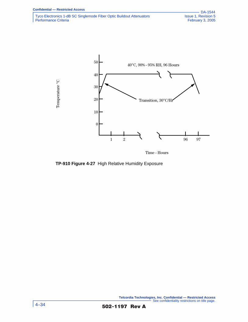
Confidential — Restricted Access
Tyco Electronics 1-dB SC Singlemode Fiber Optic Buildout Attenuators Issue 1, Revision 5Performance Criteria February 3, 2005
DA-1544
TP-910 Figure 4-27 High Relative Humidity Exposure
Transition, 30°C/Hr
Time - Hours
979621
40°C, 90% - 95% RH, 96 Hours50
40
30
20
10
0
Tem
pera
t ure
°C
�������� �� 4–34
Telcordia Technologies, Inc. Confidential — Restricted Access See confidentiality restrictions on title page.

Confidential — Restricted Access
Issue 1, Revision 5 Tyco Electronics 1-dB SC Singlemode Fiber Optic Buildout AttenuatorsFebruary 3, 2005 Performance Criteria
DA-1544
4.1.3.3 Test Flowchart (not from GR-910)
TP-910 Figure 4-28 Test Flowchart - Non-Operating Environment Test (not from GR-910)
Were thecomponents
undamaged and the optical measurements
within specs?
Document Results and go to next criteria
section
Yes
No
Clean connection points and perform initial optical
measurements
Prepare/warm-up test equipment per manufacturers’
instructions
Verify test equipment calibration
Verify lab ambient conditions of 23 ±5°C
and 30 to 70% RH
Verify product under test is configured per
supplier’s instructions
Inspect physical condition of product
under test
Stabilize product under test at room temperature with less than 50% RH
for 2 hours
Place all components in environmental chamber
Perform final optical measurements and
inspect for any physical damage
Stabilize components at room temperature for
2 hours
Document nonconformances and
address corrective actions with supplier
Run chamber control program and execute (and record results of)
daily optical measurements at
specified temperatures
Program environmental chamber to perform low
temp, high temp and high humidity tests in series
�������� �� 4–35
Telcordia Technologies, Inc. Confidential — Restricted Access See confidentiality restrictions on title page.

Confidential — Restricted Access
Tyco Electronics 1-dB SC Singlemode Fiber Optic Buildout Attenuators Issue 1, Revision 5Performance Criteria February 3, 2005
DA-1544
4.1.3.4 Test Configuration and Conditions (not from GR-910)
4.1.3.4.1 Low-Temperature Exposure and Thermal Shock
TP-910 Figure 4-29 Low-Temperature Exposure and Thermal Shock
Transition, <5° Min.
Transition, 30°C/Hr
–40°C, Any RH, 72 Hours
74 2Time - Hours
30
20
10
0
–10
–20
–30
–40
Tem
pera
ture
°C
�������� �� 4–36
Telcordia Technologies, Inc. Confidential — Restricted Access See confidentiality restrictions on title page.
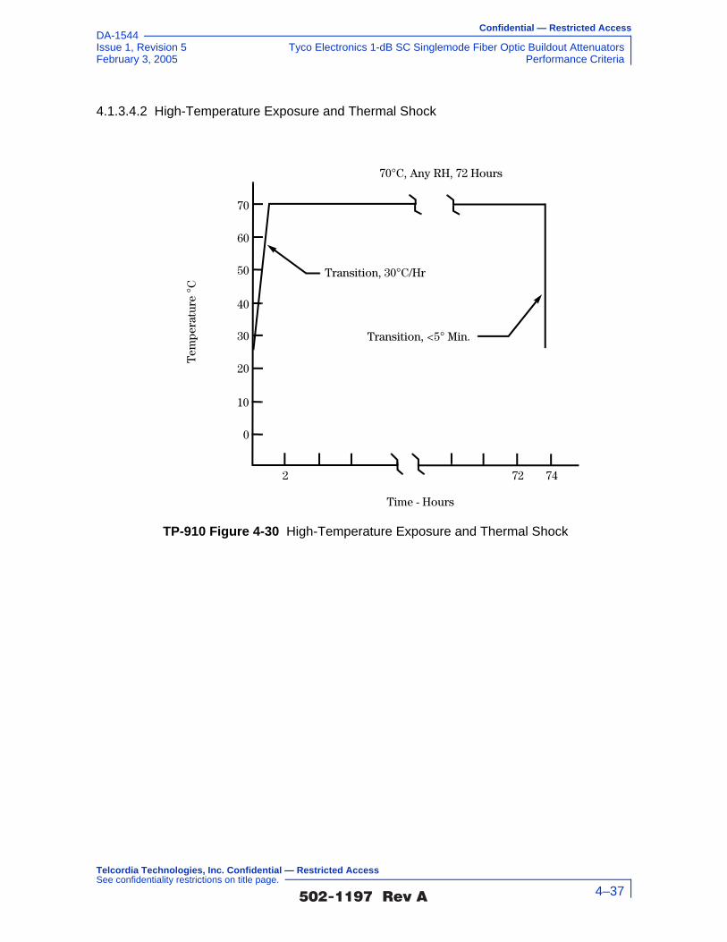
Confidential — Restricted Access
Issue 1, Revision 5 Tyco Electronics 1-dB SC Singlemode Fiber Optic Buildout AttenuatorsFebruary 3, 2005 Performance Criteria
DA-1544
4.1.3.4.2 High-Temperature Exposure and Thermal Shock
TP-910 Figure 4-30 High-Temperature Exposure and Thermal Shock
Transition, <5° Min.
Transition, 30°C/Hr
70°C, Any RH, 72 Hours
Time - Hours
2 72 74
0
10
20
30
40
50
60
70T
empe
ratu
re °
C
�������� �� 4–37
Telcordia Technologies, Inc. Confidential — Restricted Access See confidentiality restrictions on title page.

Confidential — Restricted Access
Tyco Electronics 1-dB SC Singlemode Fiber Optic Buildout Attenuators Issue 1, Revision 5Performance Criteria February 3, 2005
DA-1544
4.1.3.4.3 High Relative Humidity Exposure
Optical Measurements
For each test, compliance against the change in attenuation criteria is determined by measuring the attenuation as described in Section 5.2.2, or measure the optical transmittance and calculate the attenuation per FOTP-20, during or after each test. The compliance against the reflectance criteria is determined by measuring reflectance per FOTP-107, during or after each test. Visual and mechanical inspection should follow FOTP-13.
The operating and non-operating environmental criteria require monitoring during
testing. This can be accomplished using a Transmission Measurement Facility shown in TP-910 Figure 4-32, or another comparable system.
TP-910 Figure 4-31 High Relative Humidity Exposure
Transition, 30°C/Hr
Time - Hours
979621
40°C, 90% - 95% RH, 96 Hours50
40
30
20
10
0
Tem
pera
ture
°C
�������� �� 4–38
Telcordia Technologies, Inc. Confidential — Restricted Access See confidentiality restrictions on title page.

Confidential — Restricted Access
Issue 1, Revision 5 Tyco Electronics 1-dB SC Singlemode Fiber Optic Buildout AttenuatorsFebruary 3, 2005 Performance Criteria
DA-1544
In accordance with Verizon requirements, this facility is equipped to make measurements at four wavelengths, 1310 nm, 1490 nm, 1550 nm and 1625 nm, accurate to ±0.05 dB for transmittance and ±1 dB for reflectance down to –60 dB. While this measurement system is recommended, other configurations capable of meeting the relevant measurement requirements are acceptable. For attenuators in which the leads were connectorized by the supplier, the connectors and leads should be inside the test chamber to check for fiber pistoning. This may result in additional measurement uncertainty attributable to variations in connector loss. The measurement facility functions as follows: Switch 3 selects light from one of four laser sources emitting near λ1 = 1310 nm, λ2 = 1490 nm, λ3 = 1550 nm or λ4 = 1625 nm. The Device Under Test (DUT) is fusion spliced between the source switch (Switch 1) and the detector switch (Switch 2). The source switch is used to launch light into any of the devices under test. The detector switch connects any DUT to the power meter, measuring transmitted power and reflected power. The Coupler directs the optical power reflected by the DUT to port (r) on Switch 2 for detection. A reference fiber, located at port (m) of Switch 1 and 2, is used to correct for variations in source power over time. A reflectance reference (suggested value is −60 ±1 dB) is located at port (r) of Switch 1, and is used to calculate reflectance from the measured optical power. Insertion loss is calculated by subtracting the power transmitted through the reference fiber from the power transmitted through the DUT. Reflectance is calculated by subtracting the power reflected by the reflectance reference from the power reflected by the DUT. All other switch ports are dedicated to DUTs. The Switches, Power Meter and Environmental Chambers are computer controlled via GPIB interface.
Laser sources are preferred over LEDs because source coherence affects both the DUT reflectance, and the loss of the switches. Fusion splices are recommended for their low loss and low reflectance. To obtain accurate reflectance measurements, all components in the measurement facility, including the power meter, splices and
TP-910 Figure 4-32 Transmission Measurement Facility
Source
�������� �� 4–39
Telcordia Technologies, Inc. Confidential — Restricted Access See confidentiality restrictions on title page.

Confidential — Restricted Access
Tyco Electronics 1-dB SC Singlemode Fiber Optic Buildout Attenuators Issue 1, Revision 5Performance Criteria February 3, 2005
DA-1544
switches, should have a reflectance of ≤ −65 dB. The Coupler should have a directivity of ≥ 70 dB. Mode filters between the splices and DUT ensure single-mode transmission. A 2-meter length of the jumper cable will be a sufficient mode filter, provided that the cable conforms to the requirements of GR-409-CORE and there are at least two 360° loops in the 2 meter length. Refer to GR-326-CORE for additional details regarding measurement of loss and reflectance using the Transmission Measurement Facility.
4.1.3.5 Test Apparatus (not from GR-910)
4.1.3.6 Summary of Test Results (not from GR-910)
Conformance/Nonconformance
All of the eleven test samples conformed to the less stringent criteria in Section 4.1.3.1 of this document.
However, as shown in TP-910 Figure 4-34, the insertion loss of samples i.l.08, i.l.09 and i.l.11 showed borderline performance to the more stringent criteria of GR-910 CR4-23 [60] which states that for attenuators intended for use in digital applications, the attenuation tolerance shall not exceed ±0.15V. The insertion loss of samples i.l.08, i.l.09 and i.l.11 did not conform to, while samples i.l.01, i.l.04, i.l.07
Description Supplier ModelCalibration Cycle
Calibration Due Date.
Optical Multimeter Frame
HP 8153A - n.a.
Optical Sensor HP 81532A 12 months -
Laser Source (dual wl)
HP 81554SM 12 months -
90/10% Coupler - -
Reflectance Standard
- -
Optical Switch JDS SC95B5-00NC
n.a.
Optical Switch JDS SC95B5-00NC
n.a.
Optical Switch JDS SW1-25 CS n.a.
Env.Chamber Espec PLA2AP 12 months -
Optical Tunable Light Source
Agilent 8164A 12 months -
Sensor for tunable multimeter
Agilent 81640A 12 months -
�������� �� 4–40
Telcordia Technologies, Inc. Confidential — Restricted Access See confidentiality restrictions on title page.

Confidential — Restricted Access
Issue 1, Revision 5 Tyco Electronics 1-dB SC Singlemode Fiber Optic Buildout AttenuatorsFebruary 3, 2005 Performance Criteria
DA-1544
and i.l.10 showed borderline performance to the more stringent criteria of GR-910 CR4-24 [61] which states that for attenuators intended for use in AM video applications, the attenuation tolerance shall not exceed ±0.10V. Sample i.l.08 showed a maximum insertion loss of 1.17 ±0.05 dB, sample i.l.09 showed a maximum insertion loss of 1.18 ±0.05 dB and sample i.l.11 showed a maximum insertion loss of 1.18 ±0.05 dB.
In addition, as shown in TP-910 Figure 4-35, samples i.l.07 and i.l.08 at the 1625 nm wavelength, and i.l.10 at the 1490 nm wavelength showed borderline performance to GR-910 CR4-31 [68] which states that the maximum reflectance for attenuators intended for use in AM-VSB systems shall be ≤ –55 dB over the entire bandpass of GR-910 CR4-20 [57] and operating temperature range of –40°C to +75°C.
Furthermore, as shown in TP-910 Figure 4-35, conformance to GR-910 CO4-32 [69] which states that the maximum reflectance for attenuators intended for use in AM-VSB systems should be ≤ –65 dB over the entire bandpass of GR-910 CR4-20 [57] and operating temperature range of –40°C to +75°C was not met. This is a conditional objective and it is up to the end user to determine the significance of this nonconformance issue. Conformance is based on demonstration of no physical damage to the product under test, as well as the optical criteria described in Section 4.2.
Nonconforming deviations to GR-910 CO4-32 [69] were noted in testing.
Sample Size
Eleven samples, in accordance with 20% LTPD specified in GR-910-CORE, Issue 2, were used in the test program. In addition, eleven samples were added to serve as hot spares for replacing sample(s) with nonconformance identified in the test program.
Failure History
Not applicable.
Disposition of Nonconformance
Not applicable.
Test Data
The following charts represent the entire set of samples tested. This includes a total of eleven (11) samples of buildout attenuators (BOA). TP-910 Figure 4-33 presents change-in-attenuation measurements for each wavelength after the Low Temperature Exposure and Thermal Shock test for all of the eleven test samples at 1310 nm, 1490 nm, 1550 nm and 1625 nm. TP-910 Figure 4-34 presents insertion loss measurements (including connection losses of about 0.5 dB) for each wavelength after the Low Temperature Exposure and Thermal Shock test for all of the eleven test samples at 1310 nm, 1490 nm, 1550 nm and 1625 nm. TP-910 Figure 4-35 presents the reflectance measurements after the Low Temperature Exposure test for all of the eleven test samples at 1310 nm, 1490 nm, 1550 nm and 1625 nm.
�������� �� 4–41
Telcordia Technologies, Inc. Confidential — Restricted Access See confidentiality restrictions on title page.

Confidential — Restricted Access
Tyco Electronics 1-dB SC Singlemode Fiber Optic Buildout Attenuators Issue 1, Revision 5Performance Criteria February 3, 2005
DA-1544
TP-910 Figure 4-33 Change in Attenuation at 1310 nm, 1490 nm, 1550 nm and 1625 nm after Low Temperature Exposure and Thermal Shock test
TP-910 Figure 4-34 Insertion Loss at 1310 nm, 1490 nm, 1550 nm and 1625 nm after Low Temperature Exposure and Thermal Shock test
Tyco Electronics, 1-dB Attenuators, Non-Operating Environment,Low Temperature Exposure Test
i.l.11i.l.10i.l.09i.l.08i.l.07i.l.06i.l.05i.l.04i.l.03i.l.02i.l.01-0.6
-0.4
-0.2
0
0.2
0.4
0.6
i.l.0 1 i.l.0 2 i.l.0 3 i.l.0 4 i.l.0 5 i.l.0 6 i.l.0 7 i.l.0 8 i.l.0 9 i.l.1 0 i.l.1 1
Sample #
Chan
ge in
Atte
nuat
ion
(dB)
1310 nm1490 nm1550 nm1625 nm
AM Video
Digital
+/- 0.5 dB
Tyco Electronics, 1-dB Attenuators, Non-Operating Environment,Low Temperature Exposure Test
0.40
0.60
0.80
1.00
1.20
1.40
1.60
i.l.01 i.l.02 i.l.03 i.l.04 i.l.05 i.l.06 i.l.07 i.l.08 i.l.09 i.l.10 i.l.11Sample #
Inse
rtion
Los
s (d
B)
1310 nm1490 nm1550 nm1625 nm
AM Video
Digital
+/- 0.5 dB
�������� �� 4–42
Telcordia Technologies, Inc. Confidential — Restricted Access See confidentiality restrictions on title page.

Confidential — Restricted Access
Issue 1, Revision 5 Tyco Electronics 1-dB SC Singlemode Fiber Optic Buildout AttenuatorsFebruary 3, 2005 Performance Criteria
DA-1544
Conformance/Nonconformance
All of the eleven test samples conformed to the less stringent criteria in Section 4.1.3.1 of this document.
However, as shown in TP-910 Figure 4-36, the change in attenuation of sample i.l.11 at the 1625 nm wavelength showed borderline performance to the more stringent criteria of GR-910 CR4-22 [59] which states that for all AM video applications the maximum or minimum change in attenuation before, during, or after, any or all environmental or mechanical tests shall be ≤ 0.5 dB or ≤ 0.10A, whichever is less.
As shown in TP-910 Figure 4-37, the insertion loss of samples i.l.08 and i.l.11 at the 1550 nm wavelength did not conform to, while sample i.l.09 at the 1550 nm wavelength showed borderline performance to the more stringent criteria of GR-910 CR4-23 [60] which states that for attenuators intended for use in digital applications, the attenuation tolerance shall not exceed ±0.15V. Sample i.l.08 showed a maximum insertion loss of 1.21 ±0.05 dB at the 1550 nm wavelength. Sample i.l.11 showed a maximum insertion loss of 1.27 ±0.05 dB at the 1550 nm wavelength. The insertion loss of samples i.l.08, i.l.09 and i.l.11 at the 1550 nm wavelength did not conform to, while samples i.l.01 at the 1310 nm wavelength, i.l.04 at the 1550 nm wavelength and i.l.07 at both the 1310 nm and 1550 nm wavelengths showed borderline performance to the more stringent criteria of GR-910 CR4-24 [61] which states that for attenuators intended for use in AM
TP-910 Figure 4-35 Reflectance at 1310 nm, 1490 nm, 1550 nm and 1625 nm after Low Temperature Exposure and Thermal Shock test
Tyco Electronics, 1-dB Attenuators, Non-Operating Environment,Low Temperature Exposure Test, Reflectance
-70.0
-65.0
-60.0
-55.0
-50.0
-45.0
-40.0
-35.0
-30.0i.l.01 i.l.02 i.l.03 i.l.04 i.l.05 i.l.06 i.l.07 i.l.08 i.l.09 i.l.10 i.l.11
Sample
Refle
ctan
ce (d
B)
1310 nm 1490 nm1550 nm 1625 nmReq (D) Req (A)CR (A)
`
�������� �� 4–43
Telcordia Technologies, Inc. Confidential — Restricted Access See confidentiality restrictions on title page.
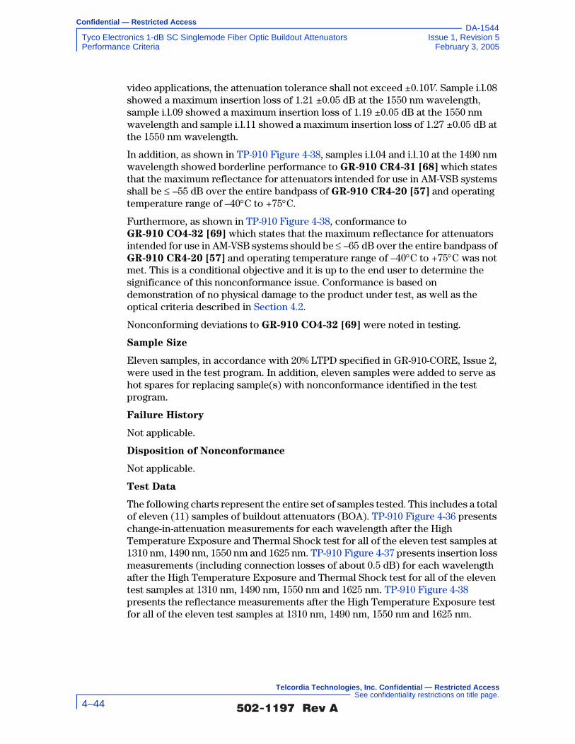
Confidential — Restricted Access
Tyco Electronics 1-dB SC Singlemode Fiber Optic Buildout Attenuators Issue 1, Revision 5Performance Criteria February 3, 2005
DA-1544
video applications, the attenuation tolerance shall not exceed ±0.10V. Sample i.l.08 showed a maximum insertion loss of 1.21 ±0.05 dB at the 1550 nm wavelength, sample i.l.09 showed a maximum insertion loss of 1.19 ±0.05 dB at the 1550 nm wavelength and sample i.l.11 showed a maximum insertion loss of 1.27 ±0.05 dB at the 1550 nm wavelength.
In addition, as shown in TP-910 Figure 4-38, samples i.l.04 and i.l.10 at the 1490 nm wavelength showed borderline performance to GR-910 CR4-31 [68] which states that the maximum reflectance for attenuators intended for use in AM-VSB systems shall be ≤ –55 dB over the entire bandpass of GR-910 CR4-20 [57] and operating temperature range of –40°C to +75°C.
Furthermore, as shown in TP-910 Figure 4-38, conformance to GR-910 CO4-32 [69] which states that the maximum reflectance for attenuators intended for use in AM-VSB systems should be ≤ –65 dB over the entire bandpass of GR-910 CR4-20 [57] and operating temperature range of –40°C to +75°C was not met. This is a conditional objective and it is up to the end user to determine the significance of this nonconformance issue. Conformance is based on demonstration of no physical damage to the product under test, as well as the optical criteria described in Section 4.2.
Nonconforming deviations to GR-910 CO4-32 [69] were noted in testing.
Sample Size
Eleven samples, in accordance with 20% LTPD specified in GR-910-CORE, Issue 2, were used in the test program. In addition, eleven samples were added to serve as hot spares for replacing sample(s) with nonconformance identified in the test program.
Failure History
Not applicable.
Disposition of Nonconformance
Not applicable.
Test Data
The following charts represent the entire set of samples tested. This includes a total of eleven (11) samples of buildout attenuators (BOA). TP-910 Figure 4-36 presents change-in-attenuation measurements for each wavelength after the High Temperature Exposure and Thermal Shock test for all of the eleven test samples at 1310 nm, 1490 nm, 1550 nm and 1625 nm. TP-910 Figure 4-37 presents insertion loss measurements (including connection losses of about 0.5 dB) for each wavelength after the High Temperature Exposure and Thermal Shock test for all of the eleven test samples at 1310 nm, 1490 nm, 1550 nm and 1625 nm. TP-910 Figure 4-38 presents the reflectance measurements after the High Temperature Exposure test for all of the eleven test samples at 1310 nm, 1490 nm, 1550 nm and 1625 nm.
�������� �� 4–44
Telcordia Technologies, Inc. Confidential — Restricted Access See confidentiality restrictions on title page.

Confidential — Restricted Access
Issue 1, Revision 5 Tyco Electronics 1-dB SC Singlemode Fiber Optic Buildout AttenuatorsFebruary 3, 2005 Performance Criteria
DA-1544
TP-910 Figure 4-36 Change in Attenuation at 1310 nm, 1490 nm, 1550 nm and 1625 nm after High Temperature Exposure and Thermal Shock test
TP-910 Figure 4-37 Insertion Loss at 1310 nm, 1490 nm, 1550 nm and 1625 nm after High Temperature Exposure and Thermal Shock test
Tyco Electronics, 1-dB Attenuators, Non-Operating Environment,High Temperature Exposure Test
i.l.01 i.l.02 i.l.03 i.l.04 i.l.05 i.l.06 i.l.07 i.l.08 i.l.09 i.l.10 i.l.11-0.60
-0.40
-0.20
0.00
0.20
0.40
0.60
i.l.0 1 i.l.0 2 i.l.0 3 i.l.0 4 i.l.0 5 i.l.0 6 i.l.0 7 i.l.0 8 i.l.0 9 i.l.1 0 i.l.1 1
Sample #
Chan
ge in
Atte
nuat
ion
(dB)
1310 nm1490 nm1550 nm1625 nm
AM Video
Digital
+/- 0.5 dB
Tyco Electronics, 1-dB Attenuators, Non-Operating Environment,High Temperature Exposure Test
0.40
0.60
0.80
1.00
1.20
1.40
1.60
i.l.01 i.l.02 i.l.03 i.l.04 i.l.05 i.l.06 i.l.07 i.l.08 i.l.09 i.l.10 i.l.11Sample #
Inse
rtion
Los
s (d
B)
1310 nm1490 nm1550 nm1625 nm
AM Video
Digital
+/- 0.5 dB
�������� �� 4–45
Telcordia Technologies, Inc. Confidential — Restricted Access See confidentiality restrictions on title page.

Confidential — Restricted Access
Tyco Electronics 1-dB SC Singlemode Fiber Optic Buildout Attenuators Issue 1, Revision 5Performance Criteria February 3, 2005
DA-1544
Conformance/Nonconformance
All of the eleven test samples conformed to the less stringent criteria in Section 4.1.3.1 of this document.
However, as shown in TP-910 Figure 4-39, the change in attenuation of sample i.l.02 at the 1550 nm wavelength showed borderline performance to the more stringent criteria of GR-910 CR4-22 [59] which states that for all AM video applications the maximum or minimum change in attenuation before, during, or after, any or all environmental or mechanical tests shall be ≤ 0.5 dB or ≤ 0.10A, whichever is less.
As shown in TP-910 Figure 4-40, the insertion loss of samples i.l.02 at the 1490 nm and 1625 nm wavelengths, i.l.05 at the 1625 nm wavelength, i.l.07 at the 1550 nm wavelength, i.l.08 at the 1550 nm wavelength, i.l.09 at the 1550 nm wavelength and i.l.11 at the 1550 nm wavelength showed borderline performance to the more stringent criteria of GR-910 CR4-23 [60] which states that for attenuators intended for use in digital applications, the attenuation tolerance shall not exceed ±0.15V. The insertion loss of samples i.l.02 at the 1490 nm and the 1625 nm wavelengths, i.l.05 at the 1625 nm wavelength, i.l.07 at the 1550 nm wavelength, i.l.08 at the 1550 nm wavelength, i.l.09 at the 1550 nm wavelength and i.l.11 at the 1550 nm wavelength did not conform to, while samples i.l.01 at the 1550 nm wavelength, i.l.02 at the 1550 nm wavelength and i.l.07 at the 1325 nm wavelength showed borderline performance to the more stringent criteria of
TP-910 Figure 4-38 Reflectance at 1310 nm, 1490 nm, 1550 nm and 1625 nm after High Temperature Exposure and Thermal Shock test
Tyco Electronics, 1-dB Attenuators, Non-Operating Environment,High Temperature Exposure Test, Reflectance
-70.0
-65.0
-60.0
-55.0
-50.0
-45.0
-40.0
-35.0
-30.0i.l.01 i.l.02 i.l.03 i.l.04 i.l.05 i.l.06 i.l.07 i.l.08 i.l.09 i.l.10 i.l.11
Sample
Refle
ctan
ce (d
B)
1310 nm 1490 nm1550 nm 1625 nmReq (D) Req (A)CR (A)
`
�������� �� 4–46
Telcordia Technologies, Inc. Confidential — Restricted Access See confidentiality restrictions on title page.

Confidential — Restricted Access
Issue 1, Revision 5 Tyco Electronics 1-dB SC Singlemode Fiber Optic Buildout AttenuatorsFebruary 3, 2005 Performance Criteria
DA-1544
GR-910 CR4-24 [61] which states that for attenuators intended for use in AM video applications, the attenuation tolerance shall not exceed ±0.10V. Sample i.l.02 showed a minimum insertion loss of 0.84 ±0.05 dB at the 1490 nm wavelength and 0.84 ±0.05 dB at the 1625 nm wavelength, sample i.l.05 showed a minimum insertion loss of 0.82 ±0.05 dB at the 1625 nm wavelength, sample i.l.07 showed a maximum insertion loss of 1.16 ±0.05 dB at the 1550 nm wavelength, sample i.l.08 showed a maximum insertion loss of 1.16 ±0.05 dB at the 1550 nm wavelength, sample i.l.09 showed a maximum insertion loss of 1.20 ±0.05 dB at the 1550 nm wavelength and sample i.l.11 showed a maximum insertion loss of 1.18 ±0.05 dB at the 1550 nm wavelength.
In addition, as shown in TP-910 Figure 4-41, samples i.l.01 and i.l.07 at the 1625 nm wavelength and i.l.11 at the 1490 nm wavelength showed borderline performance to GR-910 CR4-31 [68] which states that the maximum reflectance for attenuators intended for use in AM-VSB systems shall be ≤ –55 dB over the entire bandpass of GR-910 CR4-20 [57] and operating temperature range of –40°C to +75°C.
Furthermore, as shown in TP-910 Figure 4-41, conformance to GR-910 CO4-32 [69] which states that the maximum reflectance for attenuators intended for use in AM-VSB systems should be ≤ –65 dB over the entire bandpass of GR-910 CR4-20 [57] and operating temperature range of –40°C to +75°C was not met. This is a conditional objective and it is up to the end user to determine the significance of this nonconformance issue. Conformance is based on demonstration of no physical damage to the product under test, as well as the optical criteria described in Section 4.2.
Nonconforming deviations to GR-910 CO4-32 [69] were noted in testing.
Sample Size
Eleven samples, in accordance with 20% LTPD specified in GR-910-CORE, Issue 2, were used in the test program. In addition, eleven samples were added to serve as hot spares for replacing sample(s) with nonconformance identified in the test program.
Failure History
Not applicable.
Disposition of Nonconformance
Not applicable.
Test Data
The following charts represent the entire set of samples tested. This includes a total of eleven (11) samples of buildout attenuators (BOA). TP-910 Figure 4-39 presents change-in-attenuation measurements for each wavelength after the High Relative Humidity test for all of the eleven test samples at 1310 nm, 1490 nm, 1550 nm and 1625 nm. TP-910 Figure 4-40 presents insertion loss measurements (including connection losses of about 0.5 dB) for each wavelength after the High Relative Humidity test for all of the eleven test samples at 1310 nm, 1490 nm, 1550 nm and 1625 nm. TP-910 Figure 4-41 presents the reflectance measurements after the High
�������� �� 4–47
Telcordia Technologies, Inc. Confidential — Restricted Access See confidentiality restrictions on title page.

Confidential — Restricted Access
Tyco Electronics 1-dB SC Singlemode Fiber Optic Buildout Attenuators Issue 1, Revision 5Performance Criteria February 3, 2005
DA-1544
Relative Humidity Exposure test for all of the eleven test samples at 1310 nm, 1490 nm, 1550 nm and 1625 nm.
TP-910 Figure 4-39 Change in Attenuation at 1310 nm, 1490 nm, 1550 nm and 1625 nm after High Relative Humidity Exposure test
Tyco Electronics, 1-dB Attenuators, Non-Operating Environment,High Relative Humidity Exposure Test
i.l.11i.l.10i.l.09i.l.08i.l.07i.l.06i.l.05i.l.04i.l.03i.l.02i.l.01-0.60
-0.40
-0.20
0.00
0.20
0.40
0.60
i.l.0 1 i.l.0 2 i.l.0 3 i.l.0 4 i.l.0 5 i.l.0 6 i.l.0 7 i.l.0 8 i.l.0 9 i.l.1 0 i.l.1 1
Sample #
Chan
ge in
Atte
nuat
ion
(dB)
1310 nm1490 nm1550 nm1625 nm
AM Video
Digital
+/- 0.5 dB
�������� �� 4–48
Telcordia Technologies, Inc. Confidential — Restricted Access See confidentiality restrictions on title page.
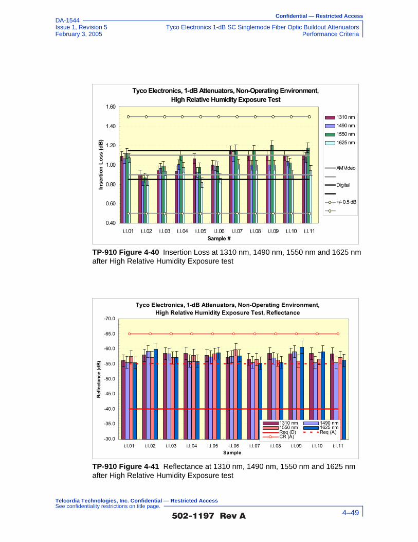
Confidential — Restricted Access
Issue 1, Revision 5 Tyco Electronics 1-dB SC Singlemode Fiber Optic Buildout AttenuatorsFebruary 3, 2005 Performance Criteria
DA-1544
TP-910 Figure 4-40 Insertion Loss at 1310 nm, 1490 nm, 1550 nm and 1625 nm after High Relative Humidity Exposure test
TP-910 Figure 4-41 Reflectance at 1310 nm, 1490 nm, 1550 nm and 1625 nm after High Relative Humidity Exposure test
Tyco Electronics, 1-dB Attenuators, Non-Operating Environment,High Relative Humidity Exposure Test
0.40
0.60
0.80
1.00
1.20
1.40
1.60
i.l.01 i.l.02 i.l.03 i.l.04 i.l.05 i.l.06 i.l.07 i.l.08 i.l.09 i.l.10 i.l.11Sample #
Inse
rtion
Los
s (d
B)
1310 nm1490 nm1550 nm1625 nm
AM Video
Digital
+/- 0.5 dB
Tyco Electronics, 1-dB Attenuators, Non-Operating Environment,High Relative Humidity Exposure Test, Reflectance
-70.0
-65.0
-60.0
-55.0
-50.0
-45.0
-40.0
-35.0
-30.0i.l.01 i.l.02 i.l.03 i.l.04 i.l.05 i.l.06 i.l.07 i.l.08 i.l.09 i.l.10 i.l.11
Sample
Refle
ctan
ce (d
B)
1310 nm 1490 nm1550 nm 1625 nmReq (D) Req (A)CR (A)
`
�������� �� 4–49
Telcordia Technologies, Inc. Confidential — Restricted Access See confidentiality restrictions on title page.

Confidential — Restricted Access
Tyco Electronics 1-dB SC Singlemode Fiber Optic Buildout Attenuators Issue 1, Revision 5Performance Criteria February 3, 2005
DA-1544
4.1.4 Humidity/Condensation Cycling Test
4.1.4.1 Criteria - Humidity/Condensation Cycling (heading not from GR-910)
GR-910 R4-6 [78] Attenuators shall meet the optical criteria and damage criteria described in Section 4.2.
Attenuator test samples are to be subjected to the Humidity/Condensation Cycling Test according to FOTP-3, per the modified temperature profile shown in Section 5.1.4. The maximum and minimum temperatures are –10°C to +65°C at 90% to 100% relative humidity at the temperatures indicated for 168 hours, (7 days).
4.1.4.2 Test Method (not from GR-910)
1. Verify that the lab ambient conditions are in the range of 23 ±5°C, and 30 to 70% relative humidity
2. Warm up/prepare and stabilize test equipment per manufacturers instructions, up to 1 hour
3. Verify that the test equipment to be used meets calibration requirements
4. Review manufacturer instructions/procedures for product under test, to assure product usage/configuration is appropriate
5. Allow product under test to stabilize at room temperature with relative humidity less than 50%, for two hours prior to initial optical power reading
6. Program thermal chamber to test cycle per FOTP-3
7. Perform initial optical power reading and record data
8. Subject product under test to temperature cycling per FOTP-3 with maximum temperature of 65°C and minimum temperature of –10°C with temperature rate of change of approximately 1°C per minute. 14 cycles must be performed and the chamber shall be programmed to assure minimum 30 minute dwells at the extremes of each cycle to assure thermal equilibrium.
9. At conclusion of ten cycles, allow product under test to stabilize at room conditions for at least 2 hours
10. Perform final optical power readings and record data
11. Inspect product under test for any physical damage and record observations
12. Record conformance status. If non-conforming, notify supplier.
�������� �� 4–50
Telcordia Technologies, Inc. Confidential — Restricted Access See confidentiality restrictions on title page.

Confidential — Restricted Access
Issue 1, Revision 5 Tyco Electronics 1-dB SC Singlemode Fiber Optic Buildout AttenuatorsFebruary 3, 2005 Performance Criteria
DA-1544
4.1.4.3 Test Flowchart (not from GR-910)
TP-910 Figure 4-42 Test Flowchart - Humidity/Condensation Cycling Test (not from GR-910)
Verify lab ambients of23C +/-5 and 30-
70%RH
Prepare/Warm-up testequipment permanufacturers
instructions
Verify test equipmentcalibration
Verify product undertest configured per
manufacturerinstructions
Stabilize product undertest at room temp withless than 50% RH for 2
hours
Place all componentsin chamber and
execute test with 10cycles of +70C to -40 C
at 1C/min change
Verify chambersettings
No MechanicalDamage and opticalreadings in spec?
Recordfindings andfollow non-conforming
process
Recordfindings and
completereport section
Test Complete
Yes
No
Stabilize componentsat room temp for 2
hours
Inspect product undertest physical condition
Clean connectionpoints and perform
initial opticalmeasurements
Perform final opticalmeasurements and
inspect for any physicaldamage
Place components in chamber and execute test with 14 cycles of
+65°C to -10°C at 1°C/min change
�������� �� 4–51
Telcordia Technologies, Inc. Confidential — Restricted Access See confidentiality restrictions on title page.

Confidential — Restricted Access
Tyco Electronics 1-dB SC Singlemode Fiber Optic Buildout Attenuators Issue 1, Revision 5Performance Criteria February 3, 2005
DA-1544
4.1.4.4 Test Configuration and Conditions (not from GR-910)
Attenuators are subjected to a temperature cycle as described in FOTP-3 with a maximum temperature of 65 ±2°C (149 ±4°F) and a minimum temperature of –10 ±2°C (14 ±4°F). The rate of temperature change is approximately 1°C per minute and dwell times at the extremes should be ≥ 30 minutes. Thermal equilibrium must be reached at the extreme temperatures. Test samples shall be subjected to 14 cycles of testing. The temperature cycle is to initiate at an ambient temperature of 23 ±5°C with a relative humidity of 30 to 70%. Within the first interval, the temperature is to decrease to –10 ±2°C and then be held for two intervals. During the fourth interval, the temperature is to increase to a maximum level of 65 ±2°C with a relative humidity ≥ 90% and be held constant for two intervals. During the seventh interval, the temperature is to decrease to a minimum level of –10 ±2°C and then be held for two intervals. During the tenth interval, the temperature is to increase back to the initial ambient temperature of 23 ±5°C with a relative humidity ≥ 90% and be held for two intervals.
Optical Measurements
For each test, compliance against the change in attenuation criteria is determined by measuring the attenuation as described in Section 5.2.2, or measure the optical transmittance and calculate the attenuation per FOTP-20, during or after each test. The compliance against the reflectance criteria is determined by measuring reflectance per FOTP-107, during or after each test. Visual and mechanical inspection should follow FOTP-13.
The operating and non-operating environmental criteria require monitoring during
testing. This can be accomplished using a Transmission Measurement Facility shown in TP-910 Figure 4-43, or another comparable system.
TP-910 Figure 4-43 Transmission Measurement Facility
Source
�������� �� 4–52
Telcordia Technologies, Inc. Confidential — Restricted Access See confidentiality restrictions on title page.

Confidential — Restricted Access
Issue 1, Revision 5 Tyco Electronics 1-dB SC Singlemode Fiber Optic Buildout AttenuatorsFebruary 3, 2005 Performance Criteria
DA-1544
In accordance with Verizon requirements, this facility is equipped to make measurements at four wavelengths, 1310 nm, 1490 nm, 1550 nm and 1625 nm, accurate to ±0.05 dB for transmittance and ±1 dB for reflectance down to –60 dB. While this measurement system is recommended, other configurations capable of meeting the relevant measurement requirements are acceptable. For attenuators in which the leads were connectorized by the supplier, the connectors and leads should be inside the test chamber to check for fiber pistoning. This may result in additional measurement uncertainty attributable to variations in connector loss. The measurement facility functions as follows: Switch 3 selects light from one of four laser sources emitting near λ1 = 1310 nm, λ2 = 1490 nm, λ3 = 1550 nm or λ4 = 1625 nm. The Device Under Test (DUT) is fusion spliced between the source switch (Switch 1) and the detector switch (Switch 2). The source switch is used to launch light into any of the devices under test. The detector switch connects any DUT to the power meter, measuring transmitted power and reflected power. The Coupler directs the optical power reflected by the DUT to port (r) on Switch 2 for detection. A reference fiber, located at port (m) of Switch 1 and 2, is used to correct for variations in source power over time. A reflectance reference (suggested value is −60 ±1 dB) is located at port (r) of Switch 1, and is used to calculate reflectance from the measured optical power. Insertion loss is calculated by subtracting the power transmitted through the reference fiber from the power transmitted through the DUT. Reflectance is calculated by subtracting the power reflected by the reflectance reference from the power reflected by the DUT. All other switch ports are dedicated to DUTs. The Switches, Power Meter and Environmental Chambers are computer controlled via GPIB interface.
Laser sources are preferred over LEDs because source coherence affects both the DUT reflectance, and the loss of the switches. Fusion splices are recommended for their low loss and low reflectance. To obtain accurate reflectance measurements, all components in the measurement facility, including the power meter, splices and switches, should have a reflectance of ≤ −65 dB. The Coupler should have a directivity of ≥ 70 dB. Mode filters between the splices and DUT ensure single-mode transmission. A 2-meter length of the jumper cable will be a sufficient mode filter, provided that the cable conforms to the requirements of GR-409-CORE and there are at least two 360° loops in the 2 meter length. Refer to GR-326-CORE for additional details regarding measurement of loss and reflectance using the Transmission Measurement Facility.
4.1.4.5 Test Apparatus (not from GR-910)
Description Supplier ModelCalibration Cycle
Calibration Due Date.
Optical Multimeter Frame
HP 8153A - n.a.
Optical Sensor HP 81532A 12 months -
�������� �� 4–53
Telcordia Technologies, Inc. Confidential — Restricted Access See confidentiality restrictions on title page.

Confidential — Restricted Access
Tyco Electronics 1-dB SC Singlemode Fiber Optic Buildout Attenuators Issue 1, Revision 5Performance Criteria February 3, 2005
DA-1544
4.1.4.6 Summary of Test Results (not from GR-910)
Conformance/Nonconformance
All of the eleven test samples conformed to the less stringent criteria in Section 4.1.4.1 of this document.
However, as shown in TP-910 Figure 4-48, the insertion loss of samples i.l.05, i.l.07, i.l.10 and i.l.11 did not conform to the more stringent criteria of GR-910 CR4-23 [60] which states that for attenuators intended for use in digital applications, the attenuation tolerance shall not exceed ±0.15V. Sample i.l.05 showed a maximum insertion loss of 1.25 ±0.05 dB, sample i.l.07 showed a maximum insertion loss of 1.25 ±0.05 dB, sample i.l.10 showed a maximum insertion loss of 1.26 ±0.05 dB and sample i.l.11 showed a maximum insertion loss of 1.21 ±0.05 dB. The insertion loss of samples i.l.05, i.l.07, i.l.10 and i.l.11 did not conform to, while samples i.l.02, i.l.08 and i.l.09 showed borderline performance to the more stringent criteria of GR-910 CR4-24 [61] which states that for attenuators intended for use in AM video applications, the attenuation tolerance shall not exceed ±0.10V. Sample i.l.05 showed a maximum insertion loss of 1.25 ±0.05 dB, sample i.l.07 showed a maximum insertion loss of 1.25 ±0.05 dB, sample i.l.10 showed a maximum insertion loss of 1.26 ±0.05 dB and sample i.l.11 showed a maximum insertion loss of 1.21 ±0.05 dB.
As shown in TP-910 Figure 4-49, the insertion loss of samples i.l.03, i.l.05, i.l.06, i.l.10 and i.l.11 did not conform to, while samples i.l.01 and i.l.04 showed borderline performance to the more stringent criteria of GR-910 CR4-23 [60] which states that for attenuators intended for use in digital applications, the attenuation
Laser Source (dual wl)
HP 81554SM 12 months -
90/10% Coupler - -
Reflectance Standard
- -
Optical Switch JDS SC95B5-00NC
n.a.
Optical Switch JDS SC95B5-00NC
n.a.
Optical Switch JDS SW1-25 CS n.a.
Env.Chamber Espec PLA2AP 12 months -
Optical Tunable Light Source
Agilent 8164A 12 months -
Sensor for tunable multimeter
Agilent 81640A 12 months -
Description Supplier ModelCalibration Cycle
Calibration Due Date.
�������� �� 4–54
Telcordia Technologies, Inc. Confidential — Restricted Access See confidentiality restrictions on title page.

Confidential — Restricted Access
Issue 1, Revision 5 Tyco Electronics 1-dB SC Singlemode Fiber Optic Buildout AttenuatorsFebruary 3, 2005 Performance Criteria
DA-1544
tolerance shall not exceed ±0.15V. Sample i.l.03 showed a maximum insertion loss of 1.20 ±0.05 dB, sample i.l.05 showed a maximum insertion loss of 1.20 ±0.05 dB, sample i.l.06 showed a maximum insertion loss of 1.22 ±0.05 dB, sample i.l.10 showed a maximum insertion loss of 1.22 ±0.05 dB and sample i.l.11 showed a maximum insertion loss of 1.25 ±0.05 dB. The insertion loss of samples i.l.01, i.l.03, i.l.05, i.l.06, i.l.09, i.l.10 and i.l.11 did not conform to, while samples i.l.04 and i.l.08 showed borderline performance to the more stringent criteria of GR-910 CR4-24 [61] which states that for attenuators intended for use in AM video applications, the attenuation tolerance shall not exceed ±0.10V. Sample i.l.01 showed a maximum insertion loss of 1.16 ±0.05 dB, sample i.l.03 showed a maximum insertion loss of 1.20 ±0.05 dB, sample i.l.05 showed a maximum insertion loss of 1.20 ±0.05 dB, sample i.l.06 showed a maximum insertion loss of 1.22 ±0.05 dB, sample i.l.09 showed a maximum insertion loss of 1.16 ±0.05 dB, sample i.l.10 showed a maximum insertion loss of 1.22 ±0.05 dB and sample i.l.11 showed a maximum insertion loss of 1.25 ±0.05 dB.
As shown in TP-910 Figure 4-50, the insertion loss of samples i.l.07, i.l.08, i.l.09 and i.l.11 did not conform to, while samples i.l.01 and i.l.04 showed borderline performance to the more stringent criteria of GR-910 CR4-23 [60] which states that for attenuators intended for use in digital applications, the attenuation tolerance shall not exceed ±0.15V. Sample i.l.07 showed a maximum insertion loss of 1.22 ±0.05 dB, sample i.l.08 showed a maximum insertion loss of 1.22 ±0.05 dB, sample i.l.09 showed a maximum insertion loss of 1.22 ±0.05 dB and sample i.l.11 showed a maximum insertion loss of 1.24 ±0.05 dB. The insertion loss of samples i.l.01, i.l.07, i.l.08, i.l.09 and i.l.11 did not conform to, while samples i.l.02, i.l.04 and i.l.09 showed borderline performance to the more stringent criteria of GR-910 CR4-24 [61] which states that for attenuators intended for use in AM video applications, the attenuation tolerance shall not exceed ±0.10V. Sample i.l.01 showed a maximum insertion loss of 1.17 ±0.05 dB, sample i.l.07 showed a maximum insertion loss of 1.22 ±0.05 dB, sample i.l.08 showed a maximum insertion loss of 1.22 ±0.05 dB, sample i.l.09 showed a maximum insertion loss of 1.22 ±0.05 dB and sample i.l.11 showed a maximum insertion loss of 1.24 ±0.05 dB.
As shown in TP-910 Figure 4-51, the insertion loss of sample i.l.05 did not conform to, while samples i.l.02 and i.l.06 showed borderline performance to the more stringent criteria of GR-910 CR4-23 [60] which states that for attenuators intended for use in digital applications, the attenuation tolerance shall not exceed ±0.15V. Sample i.l.05 showed a minimum insertion loss of 0.79 ±0.05 dB. The insertion loss of samples i.l.02, i.l.05 and i.l.06 did not conform to, while sample i.l.01 and i.l.10 showed borderline performance to the more stringent criteria of GR-910 CR4-24 [61] which states that for attenuators intended for use in AM video applications, the attenuation tolerance shall not exceed ±0.10V. Sample i.l.02 showed a minimum insertion loss of 0.83 ±0.05 dB, sample i.l.05 showed a minimum insertion loss of 0.79 ±0.05 dB and sample i.l.06 showed a minimum insertion loss of 0.83 ±0.05 dB.
In addition, as shown in TP-910 Figure 4-52, conformance to GR-910 CO4-32 [69] which states that the maximum reflectance for attenuators
�������� �� 4–55
Telcordia Technologies, Inc. Confidential — Restricted Access See confidentiality restrictions on title page.

Confidential — Restricted Access
Tyco Electronics 1-dB SC Singlemode Fiber Optic Buildout Attenuators Issue 1, Revision 5Performance Criteria February 3, 2005
DA-1544
intended for use in AM-VSB systems should be ≤ –65 dB over the entire bandpass of GR-910 CR4-20 [57] and operating temperature range of –40°C to +75°C was not met. This is a conditional objective and it is up to the end user to determine the significance of this nonconformance issue. Conformance is based on demonstration of no physical damage to the product under test, as well as the optical criteria described in Section 4.2.
Nonconforming deviations to GR-910 CO4-32 [69] were noted in testing.
Sample Size
Eleven samples, in accordance with 20% LTPD specified in GR-910-CORE, Issue 2, were used in the test program. In addition, eleven samples were added to serve as hot spares for replacing sample(s)) with nonconformance identified in the test program.
Failure History
Not applicable.
Disposition of Nonconformance
Not applicable.
Test Data
The following graphs represent the entire set of samples tested. This includes a total of eleven (11) samples of buildout attenuators (BOA). TP-910 Figure 4-44 through TP-910 Figure 4-47 present change-in-attenuation measurements during the Humidity/Condensation Cycling test for all of the eleven test samples at 1310 nm, 1490 nm, 1550 nm and 1625 nm, respectively. TP-910 Figure 4-48 through TP-910 Figure 4-51 present insertion loss measurements (including connection losses of about 0.5 dB) during the Humidity/Condensation Cycling test for all of the eleven test samples at 1310 nm, 1490 nm, 1550 nm and 1625 nm, respectively. TP-910 Figure 4-52 presents the reflectance measurements during the Humidity/Condensation Cycling test for all of the eleven test samples at 1310 nm, 1490 nm, 1550 nm and 1625 nm. It must be noted that TP-910 Figure 4-47 and TP-910 Figure 4-51 show a loss of data between 50.33 hours and 55.00 hours. This loss of data was due to a malfunction of the 1625 nm wavelength laser source used during the Humidity/Condensation Cycling test. The malfunction was discovered and corrected within a five hour period as the test continued.
�������� �� 4–56
Telcordia Technologies, Inc. Confidential — Restricted Access See confidentiality restrictions on title page.

Confidential — Restricted Access
Issue 1, Revision 5 Tyco Electronics 1-dB SC Singlemode Fiber Optic Buildout AttenuatorsFebruary 3, 2005 Performance Criteria
DA-1544
TP-910 Figure 4-44 Change in Attenuation at 1310 nm during Humidity/Condensation Cycling test
TP-910 Figure 4-45 Change in Attenuation at 1490 nm during Humidity/Condensation Cycling test
Tyco Electronics, 1-dB Attenuators, 1310 nm., Humidity/Condensation Cycling
-0.60
-0.40
-0.20
0.00
0.20
0.40
0.60
0 24 48 72 96 120 144 168Time (h)
Chan
ge in
Atte
nuat
ion
(dB)
i.l.01i.l.02i.l.03i.l.04i.l.05i.l.06i.l.07i.l.08i.l.09i.l.10i.l.11AM Video
Digital
+/- 0.5 dB
Tyco Electronics, 1-dB Attenuators, 1490 nm., Humidity/Condensation Cycling
-0.60
-0.40
-0.20
0.00
0.20
0.40
0.60
0 24 48 72 96 120 144 168Time (h)
Chan
ge in
Atte
nuat
ion
(dB)
i.l.01i.l.02i.l.03i.l.04i.l.05i.l.06i.l.07i.l.08i.l.09i.l.10i.l.11AM Video
Digital
+/- 0.5 dB
�������� �� 4–57
Telcordia Technologies, Inc. Confidential — Restricted Access See confidentiality restrictions on title page.

Confidential — Restricted Access
Tyco Electronics 1-dB SC Singlemode Fiber Optic Buildout Attenuators Issue 1, Revision 5Performance Criteria February 3, 2005
DA-1544
TP-910 Figure 4-46 Change in Attenuation at 1550 nm during Humidity/Condensation Cycling test
TP-910 Figure 4-47 Change in Attenuation at 1625 nm during Humidity/Condensation Cycling test
Tyco Electronics, 1-dB Attenuators, 1550 nm., Humidity/Condensation Cycling
-0.60
-0.40
-0.20
0.00
0.20
0.40
0.60
0 24 48 72 96 120 144 168
Time (h)
Chan
ge in
Atte
nuat
ion
(dB)
i.l.01i.l.02i.l.03i.l.04i.l.05i.l.06i.l.07i.l.08i.l.09i.l.10i.l.11AM Video
Digital
+/- 0.5 dB
Tyco Electronics, 1-dB Attenuators, 1625 nm., Humidity/Condensation Cycling
-0.60
-0.40
-0.20
0.00
0.20
0.40
0.60
0 24 48 72 96 120 144 168
Time (h)
Chan
ge in
Atte
nuat
ion
(dB)
i.l.01i.l.02i.l.03i.l.04i.l.05i.l.06i.l.07i.l.08i.l.09i.l.10i.l.11AM Video
Digital
+/- 0.5 dB
�������� �� 4–58
Telcordia Technologies, Inc. Confidential — Restricted Access See confidentiality restrictions on title page.

Confidential — Restricted Access
Issue 1, Revision 5 Tyco Electronics 1-dB SC Singlemode Fiber Optic Buildout AttenuatorsFebruary 3, 2005 Performance Criteria
DA-1544
TP-910 Figure 4-48 Insertion Loss at 1310 nm during Humidity/Condensation Cycling test
TP-910 Figure 4-49 Insertion Loss at 1490 nm during Humidity/Condensation Cycling test
Tyco Electronics, 1-dB Attenuators, 1310 nm., Humidity/Condensation Cycling
0.40
0.60
0.80
1.00
1.20
1.40
1.60
0 24 48 72 96 120 144 168
Time (h)
Inse
rtion
Los
s (d
B)
i.l.01i.l.02i.l.03i.l.04i.l.05i.l.06i.l.07i.l.08i.l.09i.l.10i.l.11AM Video
Digital
+/- 0.5 dB
Tyco Electronics, 1-dB Attenuators, 1490 nm., Humidity/Condensation Cycling
0.40
0.60
0.80
1.00
1.20
1.40
1.60
0 24 48 72 96 120 144 168
Time (h)
Inse
rtion
Los
s (d
B)
i.l.01i.l.02i.l.03i.l.04i.l.05i.l.06i.l.07i.l.08i.l.09i.l.10i.l.11AM Video
Digital
+/- 0.5 dB
�������� �� 4–59
Telcordia Technologies, Inc. Confidential — Restricted Access See confidentiality restrictions on title page.

Confidential — Restricted Access
Tyco Electronics 1-dB SC Singlemode Fiber Optic Buildout Attenuators Issue 1, Revision 5Performance Criteria February 3, 2005
DA-1544
TP-910 Figure 4-50 Insertion Loss at 1550 nm during Humidity/Condensation Cycling test
TP-910 Figure 4-51 Insertion Loss at 1625 nm during Humidity/Condensation Cycling test
Tyco Electronics, 1-dB Attenuators, 1550 nm., Humidity/Condensation Cycling
0.40
0.60
0.80
1.00
1.20
1.40
1.60
0 24 48 72 96 120 144 168
Time (h)
Inse
rtion
Los
s (d
B)
i.l.01i.l.02i.l.03i.l.04i.l.05i.l.06i.l.07i.l.08i.l.09i.l.10i.l.11AM Video
Digital
+/- 0.5 dB
Tyco Electronics, 1-dB Attenuators, 1625 nm., Humidity/Condensation Cycling
0.40
0.60
0.80
1.00
1.20
1.40
1.60
0 24 48 72 96 120 144 168
Time (h)
Inse
rtion
Los
s (d
B)
i.l.01i.l.02i.l.03i.l.04i.l.05i.l.06i.l.07i.l.08i.l.09i.l.10i.l.11AM Video
Digital
+/- 0.5 dB
�������� �� 4–60
Telcordia Technologies, Inc. Confidential — Restricted Access See confidentiality restrictions on title page.

Confidential — Restricted Access
Issue 1, Revision 5 Tyco Electronics 1-dB SC Singlemode Fiber Optic Buildout AttenuatorsFebruary 3, 2005 Performance Criteria
DA-1544
4.1.5 Water Immersion
Attenuator test samples are to be subjected to the Water Immersion Test, Section 6.2.10, of GR-1221-CORE. Test samples are to be immersed in a water (pH 5.5 ±0.5) bath at a temperature of 43° ±2°C (109 ±4°F), for 168 hours (7 days).
4.1.5.1 Criteria - Water Immersion (heading not from GR-910)
GR-910 R4-7 [44] Attenuators shall meet optical criteria and damage criteria described in Section 4.2.
The requirement and objective apply before, during and after the test.
Water found in the OSP typically has a pH between 5 and 6. The above test method is based on FOTP-12A, which may be used as an alternative to the method described in GR-1221-CORE.
TP-910 Figure 4-52 Reflectance at 1310 nm, 1490 nm, 1550 nm and 1625 nm during Humidity/Condensation Cycling test
Tyco Electronics, 1-dB Attenuators, Humidity-Condensation Cycling Test, Reflectance
-70.0
-65.0
-60.0
-55.0
-50.0
-45.0
-40.0
-35.0
-30.0i.l.01 i.l.02 i.l.03 i.l.04 i.l.05 i.l.06 i.l.07 i.l.08 i.l.09 i.l.10 i.l.11
Sample
Refle
ctan
ce (d
B)
1310 nm 1490 nm1550 nm 1625 nmReq (D) Req (A)CR (A)
`
�������� �� 4–61
Telcordia Technologies, Inc. Confidential — Restricted Access See confidentiality restrictions on title page.

Confidential — Restricted Access
Tyco Electronics 1-dB SC Singlemode Fiber Optic Buildout Attenuators Issue 1, Revision 5Performance Criteria February 3, 2005
DA-1544
4.1.5.2 Test Method (not from GR-910)
1. Verify that the lab ambient conditions are in the range of 23 ±5°C, and 30 to 70% relative humidity
2. Prepare/warm up and stabilize test equipment per manufacturers instructions, up to 1 hour
3. Verify that the test equipment to be used meets calibration requirements
4. Review manufacturer instructions/procedures for product under test, to assure product usage/configuration is appropriate
5. Allow product under test to stabilize at room temperature with relative humidity less than 50%, for two hours prior to initial optical power reading
6. Prepare water bath per FOTP-12 maintaining water temperature of 43 ± 2°C (109 ± 4°F), and adjust pH of water to be 5.5 ±0.5
7. Perform initial optical power reading and record data
8. Maintain product under test immersed in water bath for seven days
9. Optical power measurements shall be made once every day throughout the duration of the test
10. At conclusion of the seven days, allow product under test to stabilize at room conditions
11. Perform final optical power readings within 24 hours of test conclusion and record data
12. Inspect product under test for any physical damage and record observations
13. Record conformance status. If non-conforming, notify supplier.
�������� �� 4–62
Telcordia Technologies, Inc. Confidential — Restricted Access See confidentiality restrictions on title page.

Confidential — Restricted Access
Issue 1, Revision 5 Tyco Electronics 1-dB SC Singlemode Fiber Optic Buildout AttenuatorsFebruary 3, 2005 Performance Criteria
DA-1544
4.1.5.3 Test Flowchart (not from GR-910)
TP-910 Figure 4-53 Test Flowchart - Water Immersion Test (not from GR-910)
Were thecomponents
undamaged and the optical measurements
within specs?
No
Clean connection points and perform initial optical
measurementsPrepare/warm-up test
equipment per manufacturers’
instructions
Verify test equipment calibration
Verify lab ambient conditions of 23 ±5°C
and 30 to 70% RH
Verify product under test is configured per
supplier’s instructions
Inspect physical condition of product
under test
Stabilize product under test at room temperature with less than 50% RH
for 2 hours
Prepare water bath per FOTP-12 (43°C, pH=5.5)
Perform final optical measurements and
inspect for any physical damage
Stabilize components at room temperature for
24 hours
Document nonconformances and
address corrective actions with supplier
Document Results and go to next criteria
section
Yes
Immerse product under test in bath for 7 days, and make (and record
results of) optical measurements once per
day
�������� �� 4–63
Telcordia Technologies, Inc. Confidential — Restricted Access See confidentiality restrictions on title page.

Confidential — Restricted Access
Tyco Electronics 1-dB SC Singlemode Fiber Optic Buildout Attenuators Issue 1, Revision 5Performance Criteria February 3, 2005
DA-1544
4.1.5.4 Test Configuration and Conditions (not from GR-910)
This test is to be performed according to GR-1221-CORE, Section 6.2.10, Water
Immersion Test, which is based on FOTP-12. Attenuator test samples are to be subjected to immersion in water (pH 5.5 ±0.5) at 43 ±2°C (109 ±4°F) for 7 days. The pH level can be set by mixing a standard buffer solution containing sodium hydroxide and acetic acid. The pH level should be checked periodically throughout the test and compensated if it drifts. Optical transmittance and reflectance are to be monitored once/day for 7 consecutive days and 24 hours after the test samples are removed from the bath. The samples are washed and allowed to drain for 24 hours at room temperature following removal from the water bath. The final optical transmittance and reflectance is to be measured at 23°C, 24 hours following removal from the water bath. The change in attenuation and reflectance at any measurement point during or at the end of the test is to be compared against the requirements and objectives specified in GR-910 Table 4-1.
Optical Measurements
For each test, compliance against the change in attenuation criteria is determined by measuring the attenuation as described in Section 5.2.2, or measure the optical transmittance and calculate the attenuation per FOTP-20, during or after each test. The compliance against the reflectance criteria is determined by measuring reflectance per FOTP-107, during or after each test. Visual and mechanical inspection should follow FOTP-13.
The operating and non-operating environmental criteria require monitoring during
testing. This can be accomplished using a Transmission Measurement Facility shown in TP-910 Figure 4-54, or another comparable system.
In accordance with Verizon requirements, this facility is equipped to make measurements at four wavelengths, 1310 nm, 1490 nm, 1550 nm and 1625 nm,
TP-910 Figure 4-54 Transmission Measurement Facility
Source
�������� �� 4–64
Telcordia Technologies, Inc. Confidential — Restricted Access See confidentiality restrictions on title page.

Confidential — Restricted Access
Issue 1, Revision 5 Tyco Electronics 1-dB SC Singlemode Fiber Optic Buildout AttenuatorsFebruary 3, 2005 Performance Criteria
DA-1544
accurate to ±0.05 dB for transmittance and ±1 dB for reflectance down to –60 dB. While this measurement system is recommended, other configurations capable of meeting the relevant measurement requirements are acceptable. For attenuators in which the leads were connectorized by the supplier, the connectors and leads should be inside the test chamber to check for fiber pistoning. This may result in additional measurement uncertainty attributable to variations in connector loss. The measurement facility functions as follows: Switch 3 selects light from one of four laser sources emitting near λ1 = 1310 nm, λ2 = 1490 nm, λ3 = 1550 nm or λ4 = 1625 nm. The Device Under Test (DUT) is fusion spliced between the source switch (Switch 1) and the detector switch (Switch 2). The source switch is used to launch light into any of the devices under test. The detector switch connects any DUT to the power meter, measuring transmitted power and reflected power. The Coupler directs the optical power reflected by the DUT to port (r) on Switch 2 for detection. A reference fiber, located at port (m) of Switch 1 and 2, is used to correct for variations in source power over time. A reflectance reference (suggested value is −60 ±1 dB) is located at port (r) of Switch 1, and is used to calculate reflectance from the measured optical power. Insertion loss is calculated by subtracting the power transmitted through the reference fiber from the power transmitted through the DUT. Reflectance is calculated by subtracting the power reflected by the reflectance reference from the power reflected by the DUT. All other switch ports are dedicated to DUTs. The Switches, Power Meter and Environmental Chambers are computer controlled via GPIB interface.
Laser sources are preferred over LEDs because source coherence affects both the DUT reflectance, and the loss of the switches. Fusion splices are recommended for their low loss and low reflectance. To obtain accurate reflectance measurements, all components in the measurement facility, including the power meter, splices and switches, should have a reflectance of ≤ −65 dB. The Coupler should have a directivity of ≥ 70 dB. Mode filters between the splices and DUT ensure single-mode transmission. A 2-meter length of the jumper cable will be a sufficient mode filter, provided that the cable conforms to the requirements of GR-409-CORE and there are at least two 360° loops in the 2 meter length. Refer to GR-326-CORE for additional details regarding measurement of loss and reflectance using the Transmission Measurement Facility.
4.1.5.5 Test Apparatus (not from GR-910)
Description Supplier ModelCalibration Cycle
Calibration Due Date.
Optical Multimeter Frame
HP 8153A - n.a.
Optical Sensor HP 81532A 12 months -
Laser Source (dual wl)
HP 81554SM 12 months -
�������� �� 4–65
Telcordia Technologies, Inc. Confidential — Restricted Access See confidentiality restrictions on title page.

Confidential — Restricted Access
Tyco Electronics 1-dB SC Singlemode Fiber Optic Buildout Attenuators Issue 1, Revision 5Performance Criteria February 3, 2005
DA-1544
4.1.5.6 Summary of Test Results (not from GR-910)
Conformance/Nonconformance
All of the eleven test samples conformed to the less stringent criteria in Section 4.1.5.1 of this document.
However, as shown in TP-910 Figure 4-56, the change in attenuation of sample i.l.03 showed borderline performance to the more stringent criteria of GR-910 CR4-22 [59] which states that for all AM video applications the maximum or minimum change in attenuation before, during, or after, any or all environmental or mechanical tests shall be ≤ 0.5 dB or ≤ 0.10A, whichever is less.
As shown in TP-910 Figure 4-59, the insertion loss of samples i.l.05 and i.l.07 did not conform to, while sample i.l.10 showed borderline performance to the more stringent criteria of GR-910 CR4-23 [60] which states that for attenuators intended for use in digital applications, the attenuation tolerance shall not exceed ±0.15V. Sample i.l.05 showed a maximum insertion loss of 1.23 ±0.05 dB and sample i.l.07 showed a maximum insertion loss of 1.21 ±0.05 dB. The insertion loss of samples i.l.05, i.l.07 and i.l.10 did not conform to, while samples i.l.01, i.l.08, i.l.09 and i.l.11 showed borderline performance to the more stringent criteria of GR-910 CR4-24 [61] which states that for attenuators intended for use in AM video applications, the attenuation tolerance shall not exceed ±0.10V. Sample i.l.05 showed a maximum insertion loss of 1.23 ±0.05 dB, sample i.l.07 showed a maximum insertion loss of 1.21 ±0.05 dB, and sample i.l.10 showed a maximum insertion loss of 1.17 ±0.05 dB.
As shown in TP-910 Figure 4-60, the insertion loss of samples i.l.03, i.l.06, i.l.10 and i.l.11 did not conform to, while samples i.l.05 and i.l.09 showed borderline
90/10% Coupler - -
Reflectance Standard
- -
Optical Switch JDS SC95B5-00NC
n.a.
Optical Switch JDS SC95B5-00NC
n.a.
Optical Switch JDS SW1-25 CS n.a.
Water Tub with Temperature Sensor
In-house 12 months -
Optical Tunable Light Source
Agilent 8164A 12 months -
Sensor for tunable multimeter
Agilent 81640A 12 months -
Description Supplier ModelCalibration Cycle
Calibration Due Date.
�������� �� 4–66
Telcordia Technologies, Inc. Confidential — Restricted Access See confidentiality restrictions on title page.

Confidential — Restricted Access
Issue 1, Revision 5 Tyco Electronics 1-dB SC Singlemode Fiber Optic Buildout AttenuatorsFebruary 3, 2005 Performance Criteria
DA-1544
performance to the more stringent criteria of GR-910 CR4-23 [60] which states that for attenuators intended for use in digital applications, the attenuation tolerance shall not exceed ±0.15V. Sample i.l.03 showed a maximum insertion loss of 1.26 ±0.05 dB, sample i.l.06 showed a maximum insertion loss of 1.24 ±0.05 dB, sample i.l.10 showed a maximum insertion loss of 1.29 ±0.05 dB and sample i.l.11 showed a maximum insertion loss of 1.27 ±0.05 dB. The insertion loss of samples i.l.03, i.l.05, i.l.06, i.l.09, i.l.10 and i.l.11 did not conform to, while samples i.l.01 and i.l.04 showed borderline performance to the more stringent criteria of GR-910 CR4-24 [61] which states that for attenuators intended for use in AM video applications, the attenuation tolerance shall not exceed ±0.10V. Sample i.l.03 showed a maximum insertion loss of 1.26 ±0.05 dB, sample i.l.05 showed a maximum insertion loss of 1.19 ±0.05 dB, sample i.l.06 showed a maximum insertion loss of 1.24 ±0.05 dB, sample i.l.09 showed a maximum insertion loss of 1.18 ±0.05 dB, sample i.l.10 showed a maximum insertion loss of 1.29 ±0.05 dB and sample i.l.11 showed a maximum insertion loss of 1.27 ±0.05 dB.
As shown in TP-910 Figure 4-61, the insertion loss of sample i.l.11 did not conform to, while samples i.l.01, i.l.04, i.l.08 and i.l.09 showed borderline performance to the more stringent criteria of GR-910 CR4-23 [60] which states that for attenuators intended for use in digital applications, the attenuation tolerance shall not exceed ±0.15V. Sample i.l.11 showed a maximum insertion loss of 1.24 ±0.05 dB. The insertion loss of samples i.l.01, i.l.04, i.l.08, i.l.09 and i.l.11 did not conform to, while sample i.l.02 showed borderline performance to the more stringent criteria of GR-910 CR4-24 [61] which states that for attenuators intended for use in AM video applications, the attenuation tolerance shall not exceed ±0.10V. Sample i.l.01 showed a maximum insertion loss of 1.18 ±0.05 dB, sample i.l.04 showed a maximum insertion loss of 1.16 ±0.05 dB, sample i.l.08 showed a maximum insertion loss of 1.17 ±0.05 dB, sample i.l.09 showed a maximum insertion loss of 1.16 ±0.05 dB and sample i.l.11 showed a maximum insertion loss of 1.24 ±0.05 dB.
As shown in TP-910 Figure 4-62, the insertion loss of sample i.l.05 did not conform to the more stringent criteria of GR-910 CR4-23 [60] which states that for attenuators intended for use in digital applications, the attenuation tolerance shall not exceed ±0.15V. Sample i.l.05 showed a minimum insertion loss of 0.78 ±0.05 dB. The insertion loss of sample i.l.05 did not conform to, while sample i.l.01 and i.l.06 showed borderline performance to the more stringent criteria of GR-910 CR4-24 [61] which states that for attenuators intended for use in AM video applications, the attenuation tolerance shall not exceed ±0.10V. Sample i.l.05 showed a minimum insertion loss of 0.78 ±0.05 dB.
In addition, as shown in TP-910 Figure 4-63, samples i.l.01, i.l.07 and i.l.08 at the 1625 nm wavelength showed borderline performance to GR-910 CR4-31 [68] which states that the maximum reflectance for attenuators intended for use in AM-VSB systems shall be ≤ –55 dB over the entire bandpass of GR-910 CR4-20 [57] and operating temperature range of –40°C to +75°C.
Furthermore, as shown in TP-910 Figure 4-63, conformance to GR-910 CO4-32 [69] which states that the maximum reflectance for attenuators intended for use in AM-VSB systems should be ≤ –65 dB over the entire bandpass of
�������� �� 4–67
Telcordia Technologies, Inc. Confidential — Restricted Access See confidentiality restrictions on title page.

Confidential — Restricted Access
Tyco Electronics 1-dB SC Singlemode Fiber Optic Buildout Attenuators Issue 1, Revision 5Performance Criteria February 3, 2005
DA-1544
GR-910 CR4-20 [57] and operating temperature range of –40°C to +75°C was not met. This is a conditional objective and it is up to the end user to determine the significance of this nonconformance issue. Conformance is based on demonstration of no physical damage to the product under test, as well as the optical criteria described in Section 4.2.
Nonconforming deviations to GR-910 CO4-32 [69] were noted in testing.
Sample Size
Eleven samples, in accordance with 20% LTPD specified in GR-910-CORE, Issue 2, were used in the test program. In addition, eleven samples were added to serve as hot spares for replacing sample(s) with nonconformance identified in the test program.
Failure History
Not applicable.
Disposition of Nonconformance
Not applicable.
Test Data
The following graphs represent the entire set of samples tested. This includes a total of eleven (11) samples of buildout attenuators (BOA). TP-910 Figure 4-55 through TP-910 Figure 4-58 present change-in-attenuation measurements during the Water Immersion test for all of the eleven test samples at 1310 nm, 1490 nm, 1550 nm and 1625 nm, respectively. TP-910 Figure 4-59 through TP-910 Figure 4-62 present insertion loss measurements (including connection losses of about 0.5 dB) during the Water Immersion test for all of the eleven test samples at 1310 nm, 1490 nm, 1550 nm and 1625 nm, respectively. TP-910 Figure 4-63 presents the reflectance measurements during the water immersion test for all of the eleven test samples at 1310 nm, 1490 nm, 1550 nm and 1625 nm.
�������� �� 4–68
Telcordia Technologies, Inc. Confidential — Restricted Access See confidentiality restrictions on title page.
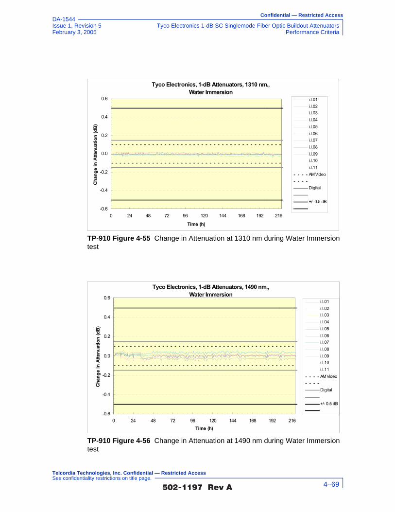
Confidential — Restricted Access
Issue 1, Revision 5 Tyco Electronics 1-dB SC Singlemode Fiber Optic Buildout AttenuatorsFebruary 3, 2005 Performance Criteria
DA-1544
TP-910 Figure 4-55 Change in Attenuation at 1310 nm during Water Immersion test
TP-910 Figure 4-56 Change in Attenuation at 1490 nm during Water Immersion test
Tyco Electronics, 1-dB Attenuators, 1310 nm., Water Immersion
-0.6
-0.4
-0.2
0.0
0.2
0.4
0.6
0 24 48 72 96 120 144 168 192 216
Time (h)
Chan
ge in
Atte
nuat
ion
(dB)
i.l.01i.l.02i.l.03i.l.04i.l.05i.l.06i.l.07i.l.08i.l.09i.l.10i.l.11AM Video
Digital
+/- 0.5 dB
Tyco Electronics, 1-dB Attenuators, 1490 nm., Water Immersion
-0.6
-0.4
-0.2
0.0
0.2
0.4
0.6
0 24 48 72 96 120 144 168 192 216Time (h)
Chan
ge in
Atte
nuat
ion
(dB)
i.l.01i.l.02i.l.03i.l.04i.l.05i.l.06i.l.07i.l.08i.l.09i.l.10i.l.11AM Video
Digital
+/- 0.5 dB
�������� �� 4–69
Telcordia Technologies, Inc. Confidential — Restricted Access See confidentiality restrictions on title page.

Confidential — Restricted Access
Tyco Electronics 1-dB SC Singlemode Fiber Optic Buildout Attenuators Issue 1, Revision 5Performance Criteria February 3, 2005
DA-1544
TP-910 Figure 4-57 Change in Attenuation at 1550 nm during Water Immersion test
TP-910 Figure 4-58 Change in Attenuation at 1625 nm during Water Immersion test
Tyco Electronics, 1-dB Attenuators, 1550 nm., Water Immersion
-0.6
-0.4
-0.2
0.0
0.2
0.4
0.6
0 24 48 72 96 120 144 168 192 216Time (h)
Chan
ge in
Atte
nuat
ion
(dB)
i.l.01i.l.02i.l.03i.l.04i.l.05i.l.06i.l.07i.l.08i.l.09i.l.10i.l.11AM Video
Digital
+/- 0.5 dB
Tyco Electronics, 1-dB Attenuators, 1625 nm., Water Immersion
-0.6
-0.4
-0.2
0.0
0.2
0.4
0.6
0 24 48 72 96 120 144 168 192 216Time (h)
Chan
ge in
Atte
nuat
ion
(dB)
i.l.01i.l.02i.l.03i.l.04i.l.05i.l.06i.l.07i.l.08i.l.09i.l.10i.l.11AM Video
Digital
+/- 0.5 dB
�������� �� 4–70
Telcordia Technologies, Inc. Confidential — Restricted Access See confidentiality restrictions on title page.

Confidential — Restricted Access
Issue 1, Revision 5 Tyco Electronics 1-dB SC Singlemode Fiber Optic Buildout AttenuatorsFebruary 3, 2005 Performance Criteria
DA-1544
TP-910 Figure 4-59 Insertion Loss at 1310 nm during Water Immersion test
TP-910 Figure 4-60 Insertion Loss at 1490 nm during Water Immersion test
Tyco Electronics, 1-dB Attenuators, 1310 nm., Water Immersion
0.40
0.60
0.80
1.00
1.20
1.40
1.60
0 24 48 72 96 120 144 168 192 216Time (h)
Inse
rtion
Los
s (d
B)i.l.01i.l.02i.l.03i.l.04i.l.05i.l.06i.l.07i.l.08i.l.09i.l.10i.l.11AM Video
Digital
+/- 0.5 dB
Tyco Electronics, 1-dB Attenuators, 1490 nm., Water Immersion
0.40
0.60
0.80
1.00
1.20
1.40
1.60
0 24 48 72 96 120 144 168 192 216Time (h)
Inse
rtion
Los
s (d
B)
i.l.01i.l.02i.l.03i.l.04i.l.05i.l.06i.l.07i.l.08i.l.09i.l.10i.l.11AM Video
Digital
+/- 0.5 dB
�������� �� 4–71
Telcordia Technologies, Inc. Confidential — Restricted Access See confidentiality restrictions on title page.

Confidential — Restricted Access
Tyco Electronics 1-dB SC Singlemode Fiber Optic Buildout Attenuators Issue 1, Revision 5Performance Criteria February 3, 2005
DA-1544
TP-910 Figure 4-61 Insertion Loss at 1550 nm during Water Immersion test
TP-910 Figure 4-62 Insertion Loss at 1625 nm during Water Immersion test
Tyco Electronics, 1-dB Attenuators, 1550 nm., Water Immersion
0.40
0.60
0.80
1.00
1.20
1.40
1.60
0 24 48 72 96 120 144 168 192 216Time (h)
Inse
rtion
Los
s (d
B)i.l.01i.l.02i.l.03i.l.04i.l.05i.l.06i.l.07i.l.08i.l.09i.l.10i.l.11AM Video
Digital
+/- 0.5 dB
Tyco Electronics, 1-dB Attenuators, 1625 nm., Water Immersion
0.40
0.60
0.80
1.00
1.20
1.40
1.60
0 24 48 72 96 120 144 168 192 216Time (h)
Inse
rtion
Los
s (d
B)
i.l .01i.l .02i.l .03i.l .04i.l .05i.l .06i.l .07i.l .08i.l .09i.l .10i.l .11AM Video
Digital
+/- 0.5 dB
�������� �� 4–72
Telcordia Technologies, Inc. Confidential — Restricted Access See confidentiality restrictions on title page.

Confidential — Restricted Access
Issue 1, Revision 5 Tyco Electronics 1-dB SC Singlemode Fiber Optic Buildout AttenuatorsFebruary 3, 2005 Performance Criteria
DA-1544
4.1.6 Vibration
Attenuator test samples are to be subjected to the Variable Frequency Vibration
Test, Section 6.2.2, of GR-1221-CORE, except that test samples are to withstand vibrations from 10 Hz to 55 Hz.
4.1.6.1 Criteria - Vibration (heading not from GR-910)
GR-910 R4-8 [45] Attenuators shall meet optical criteria and damage criteria described in Section 4.2.
The requirements and objectives apply before and after, but not during, the test.
The above test method is based on FOTP-11, which may be used as an alternative to the method described in GR-1221-CORE. During vibration testing, time variations in attenuation may be observed with an oscilloscope.
TP-910 Figure 4-63 Reflectance at 1310 nm, 1490 nm, 1550 nm and 1625 nm during Water Immersion test
Tyco Electronics, 1-dB Attenuators, Water Immersion Test, Reflectance-70.0
-65.0
-60.0
-55.0
-50.0
-45.0
-40.0
-35.0
-30.0i.l.01 i.l.02 i.l.03 i.l.04 i.l.05 i.l.06 i.l.07 i.l.08 i.l.09 i.l.10 i.l.11
Sample
Refle
ctan
ce (d
B)
1310 nm 1490 nm1550 nm 1625 nmReq (D) Req (A)CR (A)
`
�������� �� 4–73
Telcordia Technologies, Inc. Confidential — Restricted Access See confidentiality restrictions on title page.

Confidential — Restricted Access
Tyco Electronics 1-dB SC Singlemode Fiber Optic Buildout Attenuators Issue 1, Revision 5Performance Criteria February 3, 2005
DA-1544
4.1.6.2 Test Method (not from GR-910)
1. Verify that the lab ambient conditions are in the range of 23 ±5°C, and 30 to 70% relative humidity
2. Warm up/prepare and stabilize test equipment per manufacturers instructions, up to 1 hour
3. Verify that the test equipment to be used meets calibration requirements
4. Review manufacturer instructions/procedures for product under test, to assure product usage/configuration is appropriate
5. Perform initial optical power reading and record data
6. Program vibration table for modified FOTP-11, Condition 1 test (modification limits sweep range between 10 Hz to 55 Hz
7. Mount test samples to vibration table for X-axis test
8. Subject product to five sweeps of 10 Hz to 55 Hz and back to 10 Hz (each sweep should take approximately four minutes and the total test time should be 20 minutes
9. Perform final optical power readings and record data
10. Inspect product under test for any physical damage and record observations
11. Record conformance status. If non-conforming, notify supplier.
12. Repeat Step 5 to Step 11 for Y-Axis
13. Repeat Step 5 to Step 11 for Z-Axis
�������� �� 4–74
Telcordia Technologies, Inc. Confidential — Restricted Access See confidentiality restrictions on title page.

Confidential — Restricted Access
Issue 1, Revision 5 Tyco Electronics 1-dB SC Singlemode Fiber Optic Buildout AttenuatorsFebruary 3, 2005 Performance Criteria
DA-1544
4.1.6.3 Test Flowchart (not from GR-910)
TP-910 Figure 4-64 Test Flowchart - Vibration Test (not from GR-910)
Verify lab ambients of23C +/-5 and 30-
70%RH
Prepare/Warm-up testequipment permanufacturers
instructions
Verify test equipmentcalibration
Verify product undertest configured per
manufacturerinstructions
Mount test samples tovibration table for X-axis test orientation
Program vibration tablefor modified FOTP-11
test from 10 Hz to55 hz
No MechanicalDamage and opticalreadings in spec?
Recordfindings andfollow non-conforming
process
Recordfindings and
completereport section
Test Complete
Yes
No
Execute test - 5sweeps of 10 Hz to 55
Hz to 10 HzInspect product undertest physical condition
Clean connectionpoints and perform
initial opticalmeasurements
Perform final opticalmeasurements and
inspect for any physicaldamage
Repeat tests for Y-Axisand Z-Axis
�������� �� 4–75
Telcordia Technologies, Inc. Confidential — Restricted Access See confidentiality restrictions on title page.

Confidential — Restricted Access
Tyco Electronics 1-dB SC Singlemode Fiber Optic Buildout Attenuators Issue 1, Revision 5Performance Criteria February 3, 2005
DA-1544
4.1.6.4 Test Configuration and Conditions (not from GR-910)
This test is to be performed according to GR-1221-CORE, Section 6.2.2, Variable
Frequency Vibration Test, which is based on FOTP-11, Condition I, except that test samples are to withstand vibrations from 10 Hz to 55 Hz. This test subjects the samples to a simple harmonic motion having an amplitude of 1.52 mm (0.060") maximum total excursion. The frequency is to vary uniformly between 10 Hz and 55 Hz and return to 10 Hz in approximately 4 minutes. The attenuators are to be tested for 2 hours in each of three mutually perpendicular planes. Optical transmittance and reflectance are to be measured before and after the test. The change in attenuation and reflectance is the difference in measurements taken before and after the test and is to be compared against the requirements and objectives specified in GR-910 Table 4-1.
Optical Measurements
For each test, compliance against the change in attenuation criteria is determined by measuring the attenuation as described in Section 5.2.2, or measure the optical transmittance and calculate the attenuation per FOTP-20, during or after each test. The compliance against the reflectance criteria is determined by measuring reflectance per FOTP-107, during or after each test. Visual and mechanical inspection should follow FOTP-13.
The operating and non-operating environmental criteria require monitoring during
testing. This can be accomplished using a Transmission Measurement Facility shown in TP-910 Figure 4-65, or another comparable system.
In accordance with Verizon requirements, this facility is equipped to make measurements at four wavelengths, 1310 nm, 1490 nm, 1550 nm and 1625 nm, accurate to ±0.05 dB for transmittance and ±1 dB for reflectance down to –60 dB. While this measurement system is recommended, other configurations capable of
TP-910 Figure 4-65 Transmission Measurement Facility
Source
�������� �� 4–76
Telcordia Technologies, Inc. Confidential — Restricted Access See confidentiality restrictions on title page.

Confidential — Restricted Access
Issue 1, Revision 5 Tyco Electronics 1-dB SC Singlemode Fiber Optic Buildout AttenuatorsFebruary 3, 2005 Performance Criteria
DA-1544
meeting the relevant measurement requirements are acceptable. For attenuators in which the leads were connectorized by the supplier, the connectors and leads should be inside the test chamber to check for fiber pistoning. This may result in additional measurement uncertainty attributable to variations in connector loss. The measurement facility functions as follows: Switch 3 selects light from one of four laser sources emitting near λ1 = 1310 nm, λ2 = 1490 nm, λ3 = 1550 nm or λ4 = 1625 nm. The Device Under Test (DUT) is fusion spliced between the source switch (Switch 1) and the detector switch (Switch 2). The source switch is used to launch light into any of the devices under test. The detector switch connects any DUT to the power meter, measuring transmitted power and reflected power. The Coupler directs the optical power reflected by the DUT to port (r) on Switch 2 for detection. A reference fiber, located at port (m) of Switch 1 and 2, is used to correct for variations in source power over time. A reflectance reference (suggested value is −60 ±1 dB) is located at port (r) of Switch 1, and is used to calculate reflectance from the measured optical power. Insertion loss is calculated by subtracting the power transmitted through the reference fiber from the power transmitted through the DUT. Reflectance is calculated by subtracting the power reflected by the reflectance reference from the power reflected by the DUT. All other switch ports are dedicated to DUTs. The Switches, Power Meter and Environmental Chambers are computer controlled via GPIB interface.
Laser sources are preferred over LEDs because source coherence affects both the DUT reflectance, and the loss of the switches. Fusion splices are recommended for their low loss and low reflectance. To obtain accurate reflectance measurements, all components in the measurement facility, including the power meter, splices and switches, should have a reflectance of ≤ −65 dB. The Coupler should have a directivity of ≥ 70 dB. Mode filters between the splices and DUT ensure single-mode transmission. A 2-meter length of the jumper cable will be a sufficient mode filter, provided that the cable conforms to the requirements of GR-409-CORE and there are at least two 360° loops in the 2 meter length. Refer to GR-326-CORE for additional details regarding measurement of loss and reflectance using the Transmission Measurement Facility.
4.1.6.5 Test Apparatus (not from GR-910)
Description Supplier ModelCalibration Cycle
Calibration Due Date.
Optical Multimeter Frame
HP 8153A - n.a.
Optical Sensor HP 81532A 12 months -
Laser Source (dual wl)
HP 81554SM 12 months -
90/10% Coupler - -
�������� �� 4–77
Telcordia Technologies, Inc. Confidential — Restricted Access See confidentiality restrictions on title page.
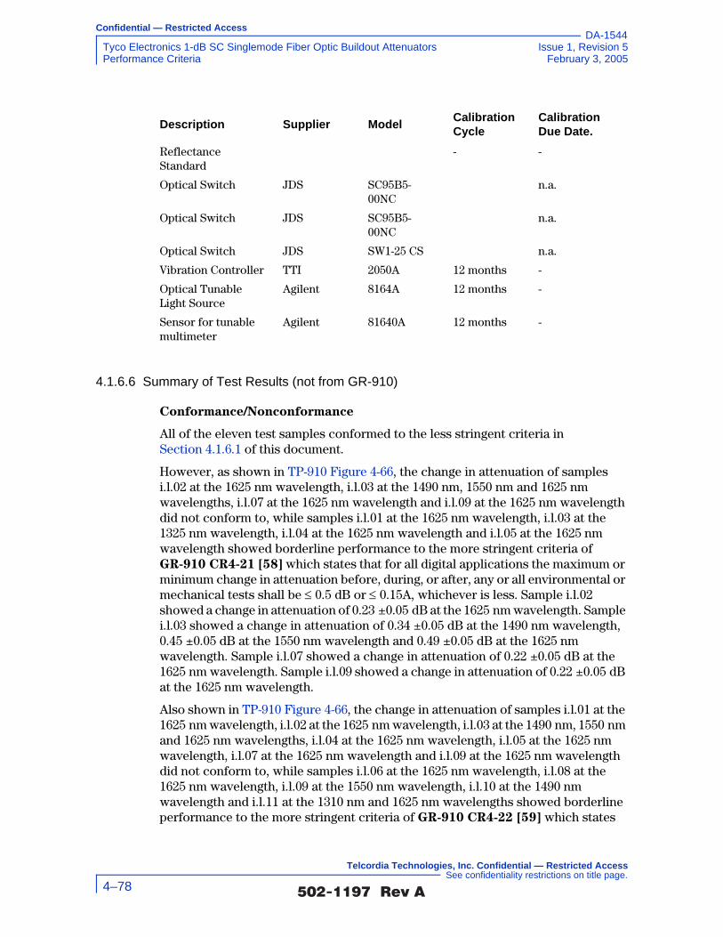
Confidential — Restricted Access
Tyco Electronics 1-dB SC Singlemode Fiber Optic Buildout Attenuators Issue 1, Revision 5Performance Criteria February 3, 2005
DA-1544
4.1.6.6 Summary of Test Results (not from GR-910)
Conformance/Nonconformance
All of the eleven test samples conformed to the less stringent criteria in Section 4.1.6.1 of this document.
However, as shown in TP-910 Figure 4-66, the change in attenuation of samples i.l.02 at the 1625 nm wavelength, i.l.03 at the 1490 nm, 1550 nm and 1625 nm wavelengths, i.l.07 at the 1625 nm wavelength and i.l.09 at the 1625 nm wavelength did not conform to, while samples i.l.01 at the 1625 nm wavelength, i.l.03 at the 1325 nm wavelength, i.l.04 at the 1625 nm wavelength and i.l.05 at the 1625 nm wavelength showed borderline performance to the more stringent criteria of GR-910 CR4-21 [58] which states that for all digital applications the maximum or minimum change in attenuation before, during, or after, any or all environmental or mechanical tests shall be ≤ 0.5 dB or ≤ 0.15A, whichever is less. Sample i.l.02 showed a change in attenuation of 0.23 ±0.05 dB at the 1625 nm wavelength. Sample i.l.03 showed a change in attenuation of 0.34 ±0.05 dB at the 1490 nm wavelength, 0.45 ±0.05 dB at the 1550 nm wavelength and 0.49 ±0.05 dB at the 1625 nm wavelength. Sample i.l.07 showed a change in attenuation of 0.22 ±0.05 dB at the 1625 nm wavelength. Sample i.l.09 showed a change in attenuation of 0.22 ±0.05 dB at the 1625 nm wavelength.
Also shown in TP-910 Figure 4-66, the change in attenuation of samples i.l.01 at the 1625 nm wavelength, i.l.02 at the 1625 nm wavelength, i.l.03 at the 1490 nm, 1550 nm and 1625 nm wavelengths, i.l.04 at the 1625 nm wavelength, i.l.05 at the 1625 nm wavelength, i.l.07 at the 1625 nm wavelength and i.l.09 at the 1625 nm wavelength did not conform to, while samples i.l.06 at the 1625 nm wavelength, i.l.08 at the 1625 nm wavelength, i.l.09 at the 1550 nm wavelength, i.l.10 at the 1490 nm wavelength and i.l.11 at the 1310 nm and 1625 nm wavelengths showed borderline performance to the more stringent criteria of GR-910 CR4-22 [59] which states
Reflectance Standard
- -
Optical Switch JDS SC95B5-00NC
n.a.
Optical Switch JDS SC95B5-00NC
n.a.
Optical Switch JDS SW1-25 CS n.a.
Vibration Controller TTI 2050A 12 months -
Optical Tunable Light Source
Agilent 8164A 12 months -
Sensor for tunable multimeter
Agilent 81640A 12 months -
Description Supplier ModelCalibration Cycle
Calibration Due Date.
�������� �� 4–78
Telcordia Technologies, Inc. Confidential — Restricted Access See confidentiality restrictions on title page.

Confidential — Restricted Access
Issue 1, Revision 5 Tyco Electronics 1-dB SC Singlemode Fiber Optic Buildout AttenuatorsFebruary 3, 2005 Performance Criteria
DA-1544
that for all AM video applications the maximum or minimum change in attenuation before, during, or after, any or all environmental or mechanical tests shall be ≤ 0.5 dB or ≤ 0.10A, whichever is less. Sample i.l.01 showed a change in attenuation of 0.19 ±0.05 dB at the 1625 nm wavelength. Sample i.l.02 showed a change in attenuation of 0.23 ±0.05 dB at the 1625 nm wavelength. Sample i.l.03 showed a change in attenuation of 0.34 ±0.05 dB at the 1490 nm wavelength, 0.45 ±0.05 dB at the 1550 nm wavelength and 0.49 ±0.05 dB at the 1625 nm wavelength. Sample i.l.04 showed a change in attenuation of 0.18 ±0.05 dB at the 1625 nm wavelength. Sample i.l.05 showed a change in attenuation of 0.18 ±0.05 dB at the 1625 nm wavelength. Sample i.l.07 showed a change in attenuation of 0.22 ±0.05 dB at the 1625 nm wavelength. Sample i.l.09 showed a change in attenuation of 0.22 ±0.05 dB at the 1625 nm wavelength.
As shown in TP-910 Figure 4-67, the insertion loss of samples i.l.01 at the 1625 nm wavelength, i.l.02 at the 1625 nm wavelength, i.l.03 at the 1310 nm, 1550 nm and 1625 nm wavelengths, i.l.04 at the 1625 nm wavelength, i.l.07 at the 1310 nm and 1625 nm wavelengths, i.l.09 at the 1550 nm and 1625 nm wavelengths, i.l.10 at the 1490 nm wavelength and i.l.11 at the 1490 nm wavelength did not conform to, while samples i.l.01 at the 1550 nm wavelength, i.l.03 at the 1490 nm wavelength, i.l.04 at the 1550 nm wavelength, i.l.05 at the 1310 nm wavelength, i.l.08 at the 1550 nm wavelength and i.l.11 at the 1550 nm wavelength showed borderline performance to the more stringent criteria of GR-910 CR4-23 [60] which states that for attenuators intended for use in digital applications, the attenuation tolerance shall not exceed ±0.15V. Sample i.l.01 showed a maximum insertion loss of 1.31 ±0.05 dB at the 1625 nm wavelength. Sample i.l.02 showed a maximum insertion loss of 1.39 ±0.05 dB at the 1625 nm wavelength. Sample i.l.03 showed a maximum insertion loss of 1.26 ±0.05 dB at the 1310 nm wavelength, 1.32 ±0.05 dB at the 1550 nm wavelength and 1.39 ±0.05 dB at the 1625 nm wavelength. Sample i.l.04 showed a maximum insertion loss of 1.26 ±0.05 dB at the 1625 nm wavelength. Sample i.l.07 showed a maximum insertion loss of 1.22 ±0.05 dB at the 1310 nm wavelength and 1.26 ±0.05 dB at the 1625 nm wavelength. Sample i.l.09 showed a maximum insertion loss of 1.27 ±0.05 dB at the 1550 nm wavelength and 1.28 ±0.05 dB at the 1625 nm wavelength. Sample i.l.10 showed a maximum insertion loss of 1.27 ±0.05 dB at the 1490 nm wavelength. Sample i.l.11 showed a maximum insertion loss of 1.24 ±0.05 dB at the 1490 nm wavelength.
Also shown in TP-910 Figure 4-67, the insertion loss of samples i.l.01 at the 1550 nm and 1625 nm wavelengths, i.l.02 at the 1625 nm wavelength, i.l.03 at the 1310 nm, 1490 nm, 1550 nm and 1625 nm wavelengths, i.l.04 at the 1550 nm and 1625 nm wavelengths, i.l.07 at the 1310 nm and 1625 nm wavelengths, i.l.08 at the 1550 nm wavelength, i.l.09 at the 1550 nm and 1625 nm wavelengths, i.l.10 at the 1490 nm wavelength and i.l.11 at the 1490 nm and 1550 nm wavelengths did not conform to, while samples i.l.01 at the 1490 nm wavelength, i.l.06 at the 1490 nm wavelength, i.l.08 at the 1310 nm and 1625 nm wavelengths and i.l.09 at the 1310 nm wavelength showed borderline performance to the more stringent criteria of GR-910 CR4-24 [61] which states that for attenuators intended for use in AM video applications, the attenuation tolerance shall not exceed ±0.10V.
�������� �� 4–79
Telcordia Technologies, Inc. Confidential — Restricted Access See confidentiality restrictions on title page.

Confidential — Restricted Access
Tyco Electronics 1-dB SC Singlemode Fiber Optic Buildout Attenuators Issue 1, Revision 5Performance Criteria February 3, 2005
DA-1544
Sample i.l.01 showed a maximum insertion loss of 1.20 ±0.05 dB at the 1550 nm wavelength and 1.31 ±0.05 dB at the 1625 nm wavelength. Sample i.l.02 showed a maximum insertion loss of 1.39 ±0.05 dB at the 1625 nm wavelength. Sample i.l.03 showed a maximum insertion loss of 1.26 ±0.05 dB at the 1310 nm wavelength, 1.20 ±0.05 dB at the 1490 nm wavelength, 1.32 ±0.05 dB at the 1550 nm wavelength and 1.39 ±0.05 dB at the 1625 nm wavelength. Sample i.l.04 showed a maximum insertion loss of 1.16 ±0.05 dB at the 1550 nm wavelength and 1.26 ±0.05 dB at the 1625 nm wavelength. Sample i.l.07 showed a maximum insertion loss of 1.22 ±0.05 dB at the 1310 nm wavelength and 1.26 ±0.05 dB at the 1625 nm wavelength. Sample i.l.08 showed a maximum insertion loss of 1.18 ±0.05 dB at the 1550 nm wavelength. Sample i.l.09 showed a maximum insertion loss of 1.27 ±0.05 dB at the 1550 nm wavelength and 1.28 ±0.05 dB at the 1625 nm wavelength. Sample i.l.10 showed a maximum insertion loss of 1.27 ±0.05 dB at the 1490 nm wavelength. Sample i.l.11 showed a maximum insertion loss of 1.24 ±0.05 dB at the 1490 nm wavelength and 1.20 ±0.05 dB at the 1550 nm wavelength.
In addition, as shown in TP-910 Figure 4-68, samples i.l.01 and i.l.08 at the 1625 nm wavelength showed borderline performance to GR-910 CR4-31 [68] which states that the maximum reflectance for attenuators intended for use in AM-VSB systems shall be ≤ –55 dB over the entire bandpass of GR-910 CR4-20 [57] and operating temperature range of –40°C to +75°C.
Furthermore, as shown in TP-910 Figure 4-68, conformance to GR-910 CO4-32 [69] which states that the maximum reflectance for attenuators intended for use in AM-VSB systems should be ≤ –65 dB over the entire bandpass of GR-910 CR4-20 [57] and operating temperature range of –40°C to +75°C was not met. This is a conditional objective and it is up to the end user to determine the significance of this nonconformance issue. Conformance is based on demonstration of no physical damage to the product under test, as well as the optical criteria described in Section 4.2.
Nonconforming deviations to GR-910 CO4-32 [69] were noted in testing.
Sample Size
Eleven samples, in accordance with 20% LTPD specified in GR-910-CORE, Issue 2, were used in the test program. In addition, eleven samples were added to serve as hot spares for replacing sample(s) with nonconformance identified in the test program.
Failure History
Not applicable.
Disposition of Nonconformance
Not applicable.
Test Data
The following charts represent the entire set of samples tested. This includes a total of eleven (11) samples of buildout attenuators (BOA). TP-910 Figure 4-66 presents
�������� �� 4–80
Telcordia Technologies, Inc. Confidential — Restricted Access See confidentiality restrictions on title page.

Confidential — Restricted Access
Issue 1, Revision 5 Tyco Electronics 1-dB SC Singlemode Fiber Optic Buildout AttenuatorsFebruary 3, 2005 Performance Criteria
DA-1544
change-in-attenuation measurements after the Vibration test for all of the eleven test samples at 1310 nm, 1490 nm, 1550 nm and 1625 nm. TP-910 Figure 4-67 presents insertion loss measurements (including connection losses of about 0.5 dB) after the Vibration test for all of the eleven test samples at 1310 nm, 1490 nm, 1550 nm and 1625 nm. TP-910 Figure 4-68 presents the reflectance measurements after the Vibration test for all of the eleven test samples at 1310 nm, 1490 nm, 1550 nm and 1625 nm.
TP-910 Figure 4-66 Change in Attenuation at 1310 nm, 1490 nm, 1550 nm and 1625 nm after Vibration test
Tyco Electronics, 1-dB Attenuators, Vibration Test
i.l.11i.l.10i.l.09i.l.08i.l.07i.l.06i.l.05i.l.04i.l.03i.l.02i.l.01-1.00
-0.80
-0.60
-0.40
-0.20
0.00
0.20
0.40
0.60
0.80
1.00
i.l.0 1 i.l.0 2 i.l.0 3 i.l.0 4 i.l.0 5 i.l.0 6 i.l.0 7 i.l.0 8 i.l.0 9 i.l.1 0 i.l.1 1
Sample #
Chan
ge in
Atte
nuat
ion
(dB)
1310 nm1490 nm1550 nm1625 nm
AM Video
Digital
+/- 0.5 dB
�������� �� 4–81
Telcordia Technologies, Inc. Confidential — Restricted Access See confidentiality restrictions on title page.

Confidential — Restricted Access
Tyco Electronics 1-dB SC Singlemode Fiber Optic Buildout Attenuators Issue 1, Revision 5Performance Criteria February 3, 2005
DA-1544
TP-910 Figure 4-67 Insertion Loss at 1310 nm, 1490 nm, 1550 nm and 1625 nm after Vibration test
TP-910 Figure 4-68 Reflectance at 1310 nm, 1490 nm, 1550 nm and 1625 nm after Vibration test
Tyco Electronics, 1-dB Attenuators, Vibration Test
0.40
0.60
0.80
1.00
1.20
1.40
1.60
i.l.01 i.l.02 i.l.03 i.l.04 i.l.05 i.l.06 i.l.07 i.l.08 i.l.09 i.l.10 i.l.11Sample #
Inse
rtion
Los
s (d
B)
1310 nm1490 nm1550 nm1625 nm
AM Video
Digital
+/- 0.5 dB
Tyco Electronics, 1-dB Attenuators, Vibration Test, Reflectance-70.0
-65.0
-60.0
-55.0
-50.0
-45.0
-40.0
-35.0
-30.0i.l.01 i.l.02 i.l.03 i.l.04 i.l.05 i.l.06 i.l.07 i.l.08 i.l.09 i.l.10 i.l.11
Sample
Refle
ctan
ce (d
B)
1310 nm 1490 nm1550 nm 1625 nmReq (D) Req (A)CR (A)
`
�������� �� 4–82
Telcordia Technologies, Inc. Confidential — Restricted Access See confidentiality restrictions on title page.

Confidential — Restricted Access
Issue 1, Revision 5 Tyco Electronics 1-dB SC Singlemode Fiber Optic Buildout AttenuatorsFebruary 3, 2005 Performance Criteria
DA-1544
4.1.7 Flex Test
Attenuator test samples are to be subjected to 100 cable flex cycles with the load specified in GR-910 Table 4-2, per FOTP-1.
4.1.7.1 Criteria - Flex (heading not from GR-910)
GR-910 R4-9 [46] Attenuators shall meet optical criteria and damage criteria described in Section 4.2.
The Flex test applies only to attenuators with optical fiber leads. The requirements and objectives apply before and after, but not during, the test.
�������� �� 4–83
Telcordia Technologies, Inc. Confidential — Restricted Access See confidentiality restrictions on title page.

Confidential — Restricted Access
Tyco Electronics 1-dB SC Singlemode Fiber Optic Buildout Attenuators Issue 1, Revision 5Performance Criteria February 3, 2005
DA-1544
4.1.7.2 Test Method (not from GR-910)
1. Verify that the lab ambient conditions are in the range of 23 ±5°C, and 30 to 70% relative humidity
2. Prepare/warm up and stabilize test equipment per manufacturers instructions, up to 1 hour
3. Verify that the test equipment to be used meets calibration requirements
4. Review manufacturer instructions/procedures for product under test, to assure product usage/configuration is appropriate
5. Perform initial optical power reading and record data
F. Prepare flex test apparatus per FOTP-1 with load based on attenuator type (Table 4-2). Rotate the angle of the test fixture arm through the following cycle: 0°, 90°, 0°, –90°, 0°, and repeat for 100 cycles.
G. Remove load
8. Perform final optical power readings and record data for each fiber after each set of 100 cycles
9. Inspect product under test for any physical damage and record observations
10. Record conformance status. If non-conforming, notify supplier.
�������� �� 4–84
Telcordia Technologies, Inc. Confidential — Restricted Access See confidentiality restrictions on title page.
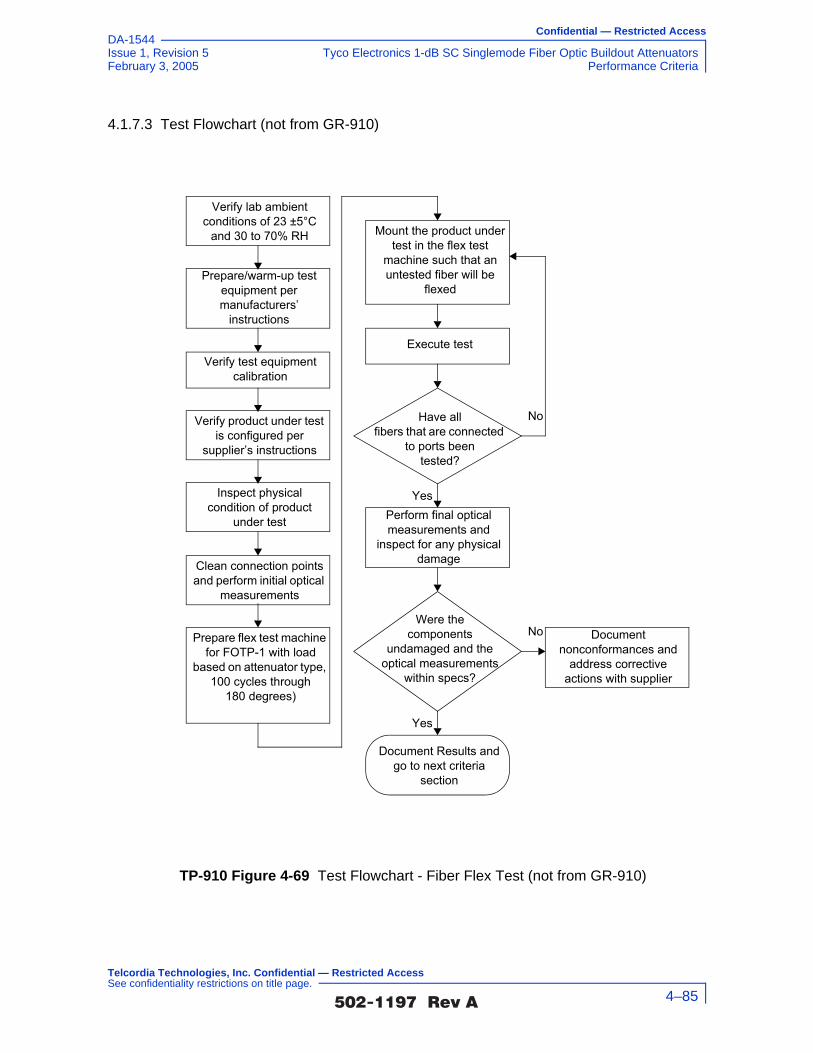
Confidential — Restricted Access
Issue 1, Revision 5 Tyco Electronics 1-dB SC Singlemode Fiber Optic Buildout AttenuatorsFebruary 3, 2005 Performance Criteria
DA-1544
4.1.7.3 Test Flowchart (not from GR-910)
TP-910 Figure 4-69 Test Flowchart - Fiber Flex Test (not from GR-910)
Clean connection points and perform initial optical
measurements
Prepare/warm-up test equipment per manufacturers’
instructions
Verify test equipment calibration
Verify lab ambient conditions of 23 ±5°C
and 30 to 70% RH
Verify product under test is configured per
supplier’s instructions
Inspect physical condition of product
under test Perform final optical measurements and
inspect for any physical damage
Prepare flex test machine for FOTP-1 with load
based on attenuator type, 100 cycles through
180 degrees)
Were thecomponents
undamaged and the optical measurements
within specs?
Yes
No Document nonconformances and
address corrective actions with supplier
Have allfibers that are connected
to ports beentested?
No
Yes
Mount the product under test in the flex test
machine such that an untested fiber will be
flexed
Document Results and go to next criteria
section
Execute test
�������� �� 4–85
Telcordia Technologies, Inc. Confidential — Restricted Access See confidentiality restrictions on title page.
Confidential — Restricted Access
Tyco Electronics 1-dB SC Singlemode Fiber Optic Buildout Attenuators Issue 1, Revision 5Performance Criteria February 3, 2005
DA-1544
4.1.7.4 Test Configuration and Conditions (not from GR-910)
Attenuator test samples are to be subjected to a modified flex test per Section 4.4.3.1 of GR-326-CORE. The flex test may be performed according to FOTP-1. The optical fiber lead(s) of the test sample shall be flexed through 180° for 100 cycles with the required load specified in GR-910 Table 4-2. The maximum change in attenuation and reflectance is the difference in measurements taken before and after the test and is to be compared against the requirements and objectives specified in Section 4.2.2 and Section 4.2.5.
This test applies only to attenuators with optical fiber leads.
A. Measure attenuation and reflectance
B. Apply load: Media Type I, 0.9 kg (2.0 lb.) Media Type II, 0.23 kg (0.5 lb.) Media Type III, 0.23 kg (0.5 lb.)
C. Rotate the angle of the test fixture arm (see TP-910 Figure 4-70) through the following cycle: 0°, 90°, 0°, –90°, 0°, and repeat for 100 cycles
D. Remove load
E. Measure attenuation and reflectance
�������� �� 4–86
Telcordia Technologies, Inc. Confidential — Restricted Access See confidentiality restrictions on title page.

Confidential — Restricted Access
Issue 1, Revision 5 Tyco Electronics 1-dB SC Singlemode Fiber Optic Buildout AttenuatorsFebruary 3, 2005 Performance Criteria
DA-1544
TP-910 Figure 4-70 Mechanical Test Facility for Flex, Twist, Side Pull and Cable Retention Tests
WEIGHTS
GUIDES
CAPSTAN7.5 Cm DIA.
ATTENUATOR
TEST ARM
22-28 Cm
CABLE OR
FIBER
90+ 90_
�������� �� 4–87
Telcordia Technologies, Inc. Confidential — Restricted Access See confidentiality restrictions on title page.

Confidential — Restricted Access
Tyco Electronics 1-dB SC Singlemode Fiber Optic Buildout Attenuators Issue 1, Revision 5Performance Criteria February 3, 2005
DA-1544
Optical Measurements
For each test, compliance against the change in attenuation criteria is determined by measuring the attenuation as described in Section 5.2.2, or measure the optical transmittance and calculate the attenuation per FOTP-20, during or after each test. The compliance against the reflectance criteria is determined by measuring reflectance per FOTP-107, during or after each test. Visual and mechanical inspection should follow FOTP-13.
The operating and non-operating environmental criteria require monitoring during
testing. This can be accomplished using a Transmission Measurement Facility shown in TP-910 Figure 4-71, or another comparable system.
In accordance with Verizon requirements, this facility is equipped to make measurements at four wavelengths, 1310 nm, 1490 nm, 1550 nm and 1625 nm, accurate to ±0.05 dB for transmittance and ±1 dB for reflectance down to –60 dB. While this measurement system is recommended, other configurations capable of meeting the relevant measurement requirements are acceptable. For attenuators in which the leads were connectorized by the supplier, the connectors and leads should be inside the test chamber to check for fiber pistoning. This may result in additional measurement uncertainty attributable to variations in connector loss. The measurement facility functions as follows: Switch 3 selects light from one of four laser sources emitting near λ1 = 1310 nm, λ1 = 1490 nm, λ1 = 1550 nm or λ2 = 1625 nm. The Device Under Test (DUT) is fusion spliced between the source switch (Switch 1) and the detector switch (Switch 2). The source switch is used to launch light into any of the devices under test. The detector switch connects any DUT to the power meter, measuring transmitted power and reflected power. The Coupler directs the optical power reflected by the DUT to port (r) on Switch 2 for detection. A reference fiber, located at port (m) of Switch 1 and 2, is used to correct for variations in source power over time. A reflectance reference (suggested value
TP-910 Figure 4-71 Transmission Measurement Facility
Source
�������� �� 4–88
Telcordia Technologies, Inc. Confidential — Restricted Access See confidentiality restrictions on title page.

Confidential — Restricted Access
Issue 1, Revision 5 Tyco Electronics 1-dB SC Singlemode Fiber Optic Buildout AttenuatorsFebruary 3, 2005 Performance Criteria
DA-1544
is −60 ±1 dB) is located at port (r) of Switch 1, and is used to calculate reflectance from the measured optical power. Insertion loss is calculated by subtracting the power transmitted through the reference fiber from the power transmitted through the DUT. Reflectance is calculated by subtracting the power reflected by the reflectance reference from the power reflected by the DUT. All other switch ports are dedicated to DUTs. The Switches, Power Meter and Environmental Chambers are computer controlled via GPIB interface.
Laser sources are preferred over LEDs because source coherence affects both the DUT reflectance, and the loss of the switches. Fusion splices are recommended for their low loss and low reflectance. To obtain accurate reflectance measurements, all components in the measurement facility, including the power meter, splices and switches, should have a reflectance of ≤ −65 dB. The Coupler should have a directivity of ≥ 70 dB. Mode filters between the splices and DUT ensure single-mode transmission. A 2-meter length of the jumper cable will be a sufficient mode filter, provided that the cable conforms to the requirements of GR-409-CORE and there are at least two 360° loops in the 2 meter length. Refer to GR-326-CORE for additional details regarding measurement of loss and reflectance using the Transmission Measurement Facility.
4.1.7.5 Test Apparatus (not from GR-910)
Description Supplier ModelCalibration Cycle
Calibration Due Date.
Optical Multimeter Frame
HP 8153A - n.a.
Optical Sensor HP 81532A 12 months -
Laser Source (dual wl)
HP 81554SM 12 months -
90/10% Coupler - -
Reflectance Standard
- -
Optical Switch JDS SC95B5-00NC
n.a.
Optical Switch JDS SC95B5-00NC
n.a.
Optical Switch JDS SW1-25 CS n.a.
Jumper Test Apparatus
In-house 12 months -
Optical Tunable Light Source
Agilent 8164A 12 months -
Sensor for tunable multimeter
Agilent 81640A 12 months -
�������� �� 4–89
Telcordia Technologies, Inc. Confidential — Restricted Access See confidentiality restrictions on title page.

Confidential — Restricted Access
Tyco Electronics 1-dB SC Singlemode Fiber Optic Buildout Attenuators Issue 1, Revision 5Performance Criteria February 3, 2005
DA-1544
4.1.7.6 Summary of Test Results (not from GR-910)
Conformance/Nonconformance
Not applicable.
Sample Size
Not applicable.
Failure History
Not applicable.
Disposition of Nonconformance
Not applicable.
Test Data
Not applicable
4.1.8 Twist Test
Attenuator test samples are to be subjected to 10 twisting cycles (in a non-operating mode) under the load specified in GR-910 Table 4-2, per FOTP-36.
4.1.8.1 Criteria - Twist (heading not from GR-910)
GR-910 R4-10 [47] Attenuators shall meet optical criteria and damage criteria described in Section 4.2.
The Twist test applies only to attenuators with optical fiber leads. The requirements and objectives apply before and after, but not during, the test.
4.1.8.2 Test Method (not from GR-910)
1. Verify that the lab ambient conditions are in the range of 23 ±5°C, and 30 to 70% relative humidity
2. Prepare/warm up and stabilize test equipment per manufacturers instructions, up to 1 hour
3. Verify that the test equipment to be used meets calibration requirements
4. Review manufacturer instructions/procedures for product under test, to assure product usage/configuration is appropriate
5. Perform initial optical power reading and record data
6. Prepare twist test apparatus per FOTP-36 and parameters: 0.45 kg, 10 cycles
�������� �� 4–90
Telcordia Technologies, Inc. Confidential — Restricted Access See confidentiality restrictions on title page.

Confidential — Restricted Access
Issue 1, Revision 5 Tyco Electronics 1-dB SC Singlemode Fiber Optic Buildout AttenuatorsFebruary 3, 2005 Performance Criteria
DA-1544
7. Apply load based on Media Type Media Type I, 1.35 kgf (3.0 lbf.) Media Type II, 0.75 kgf (1.65 lbf.) Media Type III, 0.5 kgf (1.1 lbf.)
8. Rotate the capstan (see figure below) X revolutions about the axis of the fiber, where X=2.5 for Media Type 1 and X=1.5 for Media Types II and III
9. Reverse direction and rotate Y revolutions, where Y=5 for Media Type 1 and Y=3 for Media Types II and III. Reverse direction again, and rotate Y revolutions.
10. Perform final optical power readings and record data for each fiber after each set of 10 cycles
11. Inspect product under test for any physical damage and record observations
12. Record conformance status. If non-conforming, notify supplier.
�������� �� 4–91
Telcordia Technologies, Inc. Confidential — Restricted Access See confidentiality restrictions on title page.

Confidential — Restricted Access
Tyco Electronics 1-dB SC Singlemode Fiber Optic Buildout Attenuators Issue 1, Revision 5Performance Criteria February 3, 2005
DA-1544
4.1.8.3 Test Flowchart (not from GR-910)
TP-910 Figure 4-72 Test Flowchart - Fiber Twist Test (not from GR-910)
Clean connection points and perform initial optical
measurements
Prepare/warm-up test equipment per manufacturers’
instructions
Verify test equipment calibration
Verify lab ambient conditions of 23 ±5°C
and 30 to 70% RH
Verify product under test is configured per
supplier’s instructions
Inspect physical condition of product
under test Perform final optical measurements and
inspect for any physical damage
Prepare twist test apparatus for FOTP-36
with load based on attenuator type;10 cycles
Were thecomponents
undamaged and the optical measurements
within specs?
Yes
No Document nonconformances and
address corrective actions with supplier
Have allfibers that are connected
to ports beentested?
No
Yes
Mount the product under test in the twist test
apparatus such that an untested fiber will be
twisted
Document Results and go to next criteria
section
Execute test
�������� �� 4–92
Telcordia Technologies, Inc. Confidential — Restricted Access See confidentiality restrictions on title page.

Confidential — Restricted Access
Issue 1, Revision 5 Tyco Electronics 1-dB SC Singlemode Fiber Optic Buildout AttenuatorsFebruary 3, 2005 Performance Criteria
DA-1544
4.1.8.4 Test Configuration and Conditions (not from GR-910)
Attenuator test samples are to be subjected to a modified twist test per Section 4.4.2.3 of GR-326-CORE. The twist test may be performed according to FOTP-36. The optical fiber lead(s) of the test sample shall be twisted for 10 cycles with the required load specified in GR-910 Table 4-2. The maximum change in attenuation and reflectance is the difference in measurements taken before and after the test and is to be compared against the requirements and objectives specified in Section 4.2.2 and Section 4.2.5.
A. Mount the test sample in the test facility; see TP-910 Figure 4-73
B. Measure attenuation and reflectance
C. Apply load: Media Type I, 1.35 kg (3.0 lb.) Media Type II, 0.75 kg (1.65 lb.) Media Type III, 0.5 kg (1.1 lb.)
D. Rotate the capstan (see TP-910 Figure 4-73) X revolutions about the axis of the fiber. (See the following table.)
E. Reverse direction and rotate Y revolutions. Reverse direction again, and rotate Y revolutions. See TP-910 Table 4-1.
F. Repeat step “E.” nine times
G. Remove load, and measure attenuation and reflectance.
The test may be conducted with a fixture as illustrated in TP-910 Figure 4-73.
TP-910 Table 4-1 Number of Turns for Twist Test
Media Types X Y
Type I 2.5 5
Types II & III 1.5 3
�������� �� 4–93
Telcordia Technologies, Inc. Confidential — Restricted Access See confidentiality restrictions on title page.

Confidential — Restricted Access
Tyco Electronics 1-dB SC Singlemode Fiber Optic Buildout Attenuators Issue 1, Revision 5Performance Criteria February 3, 2005
DA-1544
TP-910 Figure 4-73 Mechanical Test Facility for Flex, Twist, Side Pull and Cable Retention Tests
WEIGHTS
GUIDES
CAPSTAN7.5 Cm DIA.
ATTENUATOR
TEST ARM
22-28 Cm
CABLE OR
FIBER
90+ 90_
�������� �� 4–94
Telcordia Technologies, Inc. Confidential — Restricted Access See confidentiality restrictions on title page.

Confidential — Restricted Access
Issue 1, Revision 5 Tyco Electronics 1-dB SC Singlemode Fiber Optic Buildout AttenuatorsFebruary 3, 2005 Performance Criteria
DA-1544
Optical Measurements
For each test, compliance against the change in attenuation criteria is determined by measuring the attenuation as described in Section 5.2.2, or measure the optical transmittance and calculate the attenuation per FOTP-20, during or after each test. The compliance against the reflectance criteria is determined by measuring reflectance per FOTP-107, during or after each test. Visual and mechanical inspection should follow FOTP-13.
The operating and non-operating environmental criteria require monitoring during
testing. This can be accomplished using a Transmission Measurement Facility shown in TP-910 Figure 4-74, or another comparable system.
In accordance with Verizon requirements, this facility is equipped to make measurements at four wavelengths, 1310 nm, 1490 nm, 1550 nm and 1625 nm, accurate to ±0.05 dB for transmittance and ±1 dB for reflectance down to –60 dB. While this measurement system is recommended, other configurations capable of meeting the relevant measurement requirements are acceptable. For attenuators in which the leads were connectorized by the supplier, the connectors and leads should be inside the test chamber to check for fiber pistoning. This may result in additional measurement uncertainty attributable to variations in connector loss. The measurement facility functions as follows: Switch 3 selects light from one of four laser sources emitting near λ1 = 1310 nm, λ2 = 1490 nm, λ3 = 1550 nm or λ4 = 1625 nm. The Device Under Test (DUT) is fusion spliced between the source switch (Switch 1) and the detector switch (Switch 2). The source switch is used to launch light into any of the devices under test. The detector switch connects any DUT to the power meter, measuring transmitted power and reflected power. The Coupler directs the optical power reflected by the DUT to port (r) on Switch 2 for detection. A reference fiber, located at port (m) of Switch 1 and 2, is used to correct for variations in source power over time. A reflectance reference (suggested value
TP-910 Figure 4-74 Transmission Measurement Facility
Source
�������� �� 4–95
Telcordia Technologies, Inc. Confidential — Restricted Access See confidentiality restrictions on title page.
Confidential — Restricted Access
Tyco Electronics 1-dB SC Singlemode Fiber Optic Buildout Attenuators Issue 1, Revision 5Performance Criteria February 3, 2005
DA-1544
is −60 ±1 dB) is located at port (r) of Switch 1, and is used to calculate reflectance from the measured optical power. Insertion loss is calculated by subtracting the power transmitted through the reference fiber from the power transmitted through the DUT. Reflectance is calculated by subtracting the power reflected by the reflectance reference from the power reflected by the DUT. All other switch ports are dedicated to DUTs. The Switches, Power Meter and Environmental Chambers are computer controlled via GPIB interface.
Laser sources are preferred over LEDs because source coherence affects both the DUT reflectance, and the loss of the switches. Fusion splices are recommended for their low loss and low reflectance. To obtain accurate reflectance measurements, all components in the measurement facility, including the power meter, splices and switches, should have a reflectance of ≤ −65 dB. The Coupler should have a directivity of ≥ 70 dB. Mode filters between the splices and DUT ensure single-mode transmission. A 2-meter length of the jumper cable will be a sufficient mode filter, provided that the cable conforms to the requirements of GR-409-CORE and there are at least two 360° loops in the 2 meter length. Refer to GR-326-CORE for additional details regarding measurement of loss and reflectance using the Transmission Measurement Facility.
4.1.8.5 Test Apparatus (not from GR-910)
Description Supplier ModelCalibration Cycle
Calibration Due Date.
Optical Multimeter Frame
HP 8153A - n.a.
Optical Sensor HP 81532A 12 months -
Laser Source (dual wl)
HP 81554SM 12 months -
90/10% Coupler - -
Reflectance Standard
- -
Optical Switch JDS SC95B5-00NC
n.a.
Optical Switch JDS SC95B5-00NC
n.a.
Optical Switch JDS SW1-25 CS n.a.
Jumper Test Apparatus
In-house 12 months -
Optical Tunable Light Source
Agilent 8164A 12 months -
Sensor for tunable multimeter
Agilent 81640A 12 months -
�������� �� 4–96
Telcordia Technologies, Inc. Confidential — Restricted Access See confidentiality restrictions on title page.
Confidential — Restricted Access
Issue 1, Revision 5 Tyco Electronics 1-dB SC Singlemode Fiber Optic Buildout AttenuatorsFebruary 3, 2005 Performance Criteria
DA-1544
4.1.8.6 Summary of Test Results (not from GR-910)
Conformance/Nonconformance
Not applicable.
Sample Size
Not applicable.
Failure History
Not applicable.
Disposition of Nonconformance
Not applicable.
Test Data
Not applicable
4.1.9 Side Pull Load
Attenuator test samples are to be subjected to the tensile load specified in GR-910 Table 4-2, with the load applied at a angle of 90°. The Side Pull test applies to all attenuators. Refer to GR-326-CORE for more details on this test.
4.1.9.1 Criteria - Side Pull Load (heading not from GR-910)
GR-910 R4-11 [48] Attenuators shall meet optical criteria and damage criteria described in Section 4.2.
The requirements and objectives apply before, during and after the test.
4.1.9.2 Test Method (not from GR-910)
1. Verify that the lab ambient conditions are in the range of 23 ±5°C, and 30 to 70% relative humidity
2. Prepare/warm up and stabilize test equipment per manufacturers instructions, up to 1 hour
3. Verify that the test equipment to be used meets calibration requirements
4. Review manufacturer instructions/procedures for product under test, to assure product usage/configuration is appropriate
5. Perform initial optical power reading and record data
6. Mount the test sample in the test facility as shown in TP-910 Figure 4-76
�������� �� 4–97
Telcordia Technologies, Inc. Confidential — Restricted Access See confidentiality restrictions on title page.

Confidential — Restricted Access
Tyco Electronics 1-dB SC Singlemode Fiber Optic Buildout Attenuators Issue 1, Revision 5Performance Criteria February 3, 2005
DA-1544
7. Apply 1.25 kgf (2.75 lbf) at 90° for at least 5 seconds
8. Remove the load, and after at least 20 seconds, measure loss and reflectance
9. Inspect product under test for any physical damage and record observations
10. Record conformance status. If non-conforming, notify supplier.
�������� �� 4–98
Telcordia Technologies, Inc. Confidential — Restricted Access See confidentiality restrictions on title page.

Confidential — Restricted Access
Issue 1, Revision 5 Tyco Electronics 1-dB SC Singlemode Fiber Optic Buildout AttenuatorsFebruary 3, 2005 Performance Criteria
DA-1544
4.1.9.3 Test Flowchart (not from GR-910)
TP-910 Figure 4-75 Test Flowchart - Fiber Side Pull Test (not from GR-910)
Clean connection points and perform initial optical
measurements
Execute tests side pulls of 2.75 lbfVerify test equipment
calibration
Verify lab ambient conditions of 23 ±5°C
and 30 to 70% RH
Verify product under test is configured per
supplier’s instructions
Inspect physical condition of product
under testPerform final optical measurements and
inspect for any physical damage
Prepare tensile load test apparatus in accordance
with the specified parameters
Were thecomponents
undamaged and the optical measurements
within specs?
Yes
No Document nonconformances and
address corrective actions with supplier
Have allfibers that are connected
to ports beentested?
No
Yes
Mount the product under test in the tensile load test
apparatus such that an untested fiber will be
stressed
Document Results and go to next criteria
section
Prepare/warm-up test equipment per manufacturers’
instructions
�������� �� 4–99
Telcordia Technologies, Inc. Confidential — Restricted Access See confidentiality restrictions on title page.

Confidential — Restricted Access
Tyco Electronics 1-dB SC Singlemode Fiber Optic Buildout Attenuators Issue 1, Revision 5Performance Criteria February 3, 2005
DA-1544
4.1.9.4 Test Configuration and Conditions (Not from GR-910)
Attenuator test samples are to be subjected to the required tensile side load in an operating mode. The optical fiber lead(s) of the test sample shall be tested with the required load, specified in TP-910 Table 4-2, applied at an angle of 90°. The maximum change in attenuation and reflectance is the difference in measurements taken before, during and after the test and is to be compared against the requirements and objectives specified in Section 4.2.2 and Section 4.2.5.
The Side Pull test is based on the Equilibrium Tensile Loading Test in Section 4.4.3.5 of GR-326-CORE.
Mount the test sample in the test facility of TP-910 Figure 4-76.
The test is conducted as follows:
A. Measure both loss and reflectance
B. Apply the load listed in TP-910 Table 4-2 at an angle of 90°
C. Measure both loss and reflectance after 5 seconds
D. Remove the load and measure attenuation and reflectance after 10 seconds
The test may be conducted with a fixture as illustrated in TP-910 Figure 4-76 below.
TP-910 Table 4-2 Side Pull Tensile Loading
Media Type Load
Media I 1.25 kg (2.75 lb)
Media II 0.25 kg (0.55 lb)
Media III 0.25 kg (0.55 lb)
�������� �� 4–100
Telcordia Technologies, Inc. Confidential — Restricted Access See confidentiality restrictions on title page.

Confidential — Restricted Access
Issue 1, Revision 5 Tyco Electronics 1-dB SC Singlemode Fiber Optic Buildout AttenuatorsFebruary 3, 2005 Performance Criteria
DA-1544
TP-910 Figure 4-76 Mechanical Test Facility for Flex, Twist, Side Pull and Cable Retention Tests
WEIGHTS
GUIDES
CAPSTAN7.5 Cm DIA.
ATTENUATOR
TEST ARM
22-28 Cm
CABLE OR
FIBER
90+ 90_
�������� �� 4–101
Telcordia Technologies, Inc. Confidential — Restricted Access See confidentiality restrictions on title page.
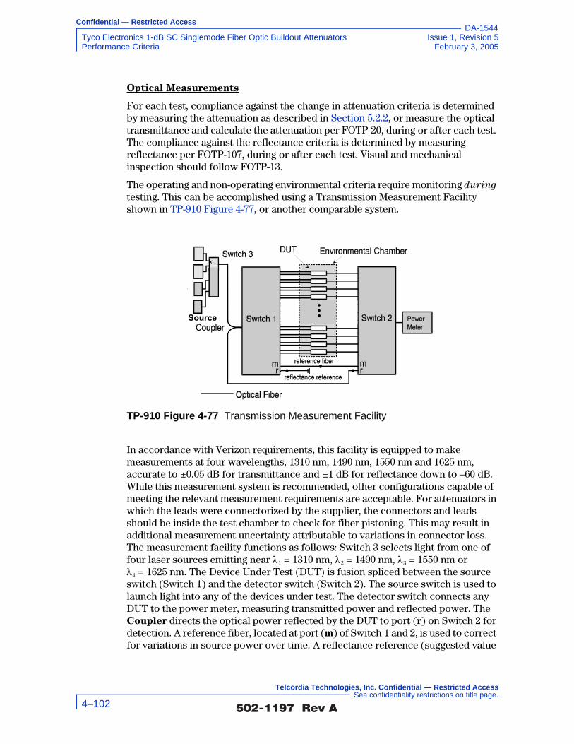
Confidential — Restricted Access
Tyco Electronics 1-dB SC Singlemode Fiber Optic Buildout Attenuators Issue 1, Revision 5Performance Criteria February 3, 2005
DA-1544
Optical Measurements
For each test, compliance against the change in attenuation criteria is determined by measuring the attenuation as described in Section 5.2.2, or measure the optical transmittance and calculate the attenuation per FOTP-20, during or after each test. The compliance against the reflectance criteria is determined by measuring reflectance per FOTP-107, during or after each test. Visual and mechanical inspection should follow FOTP-13.
The operating and non-operating environmental criteria require monitoring during
testing. This can be accomplished using a Transmission Measurement Facility shown in TP-910 Figure 4-77, or another comparable system.
In accordance with Verizon requirements, this facility is equipped to make measurements at four wavelengths, 1310 nm, 1490 nm, 1550 nm and 1625 nm, accurate to ±0.05 dB for transmittance and ±1 dB for reflectance down to –60 dB. While this measurement system is recommended, other configurations capable of meeting the relevant measurement requirements are acceptable. For attenuators in which the leads were connectorized by the supplier, the connectors and leads should be inside the test chamber to check for fiber pistoning. This may result in additional measurement uncertainty attributable to variations in connector loss. The measurement facility functions as follows: Switch 3 selects light from one of four laser sources emitting near λ1 = 1310 nm, λ2 = 1490 nm, λ3 = 1550 nm or λ4 = 1625 nm. The Device Under Test (DUT) is fusion spliced between the source switch (Switch 1) and the detector switch (Switch 2). The source switch is used to launch light into any of the devices under test. The detector switch connects any DUT to the power meter, measuring transmitted power and reflected power. The Coupler directs the optical power reflected by the DUT to port (r) on Switch 2 for detection. A reference fiber, located at port (m) of Switch 1 and 2, is used to correct for variations in source power over time. A reflectance reference (suggested value
TP-910 Figure 4-77 Transmission Measurement Facility
Source
�������� �� 4–102
Telcordia Technologies, Inc. Confidential — Restricted Access See confidentiality restrictions on title page.

Confidential — Restricted Access
Issue 1, Revision 5 Tyco Electronics 1-dB SC Singlemode Fiber Optic Buildout AttenuatorsFebruary 3, 2005 Performance Criteria
DA-1544
is −60 ±1 dB) is located at port (r) of Switch 1, and is used to calculate reflectance from the measured optical power. Insertion loss is calculated by subtracting the power transmitted through the reference fiber from the power transmitted through the DUT. Reflectance is calculated by subtracting the power reflected by the reflectance reference from the power reflected by the DUT. All other switch ports are dedicated to DUTs. The Switches, Power Meter and Environmental Chambers are computer controlled via GPIB interface.
Laser sources are preferred over LEDs because source coherence affects both the DUT reflectance, and the loss of the switches. Fusion splices are recommended for their low loss and low reflectance. To obtain accurate reflectance measurements, all components in the measurement facility, including the power meter, splices and switches, should have a reflectance of ≤ −65 dB. The Coupler should have a directivity of ≥ 70 dB. Mode filters between the splices and DUT ensure single-mode transmission. A 2-meter length of the jumper cable will be a sufficient mode filter, provided that the cable conforms to the requirements of GR-409-CORE and there are at least two 360° loops in the 2 meter length. Refer to GR-326-CORE for additional details regarding measurement of loss and reflectance using the Transmission Measurement Facility.
4.1.9.5 Test Apparatus (not from GR-910)
Description Supplier ModelCalibration Cycle
Calibration Due Date.
Optical Multimeter Frame
HP 8153A - n.a.
Optical Sensor HP 81532A 12 months -
Laser Source (dual wl)
HP 81554SM 12 months -
90/10% Coupler - -
Reflectance Standard
- -
Optical Switch JDS SC95B5-00NC
n.a.
Optical Switch JDS SC95B5-00NC
n.a.
Optical Switch JDS SW1-25 CS n.a.
Jumper Test Apparatus
In-house 12 months -
Optical Tunable Light Source
Agilent 8164A 12 months -
Sensor for tunable multimeter
Agilent 81640A 12 months -
�������� �� 4–103
Telcordia Technologies, Inc. Confidential — Restricted Access See confidentiality restrictions on title page.

Confidential — Restricted Access
Tyco Electronics 1-dB SC Singlemode Fiber Optic Buildout Attenuators Issue 1, Revision 5Performance Criteria February 3, 2005
DA-1544
4.1.9.6 Summary of Test Results (not from GR-910)
Conformance/Nonconformance
All of the eleven test samples conformed to the less stringent criteria in Section 4.1.9.1 of this document.
However, as shown in TP-910 Figure 4-79, the insertion loss of samples i.l.01 at the 1625 nm wavelength, i.l.10 at the 1310 nm and 1490 nm wavelengths and i.l.11 at the 1550 nm wavelength showed borderline performance to the less stringent criteria of GR-910 CR4-23 [60] which states that for attenuators intended for use in digital applications, the attenuation tolerance shall not exceed ±0.15V, modified to ±0.5 dB, and to the less stringent criteria of GR-910 CR4-24 [61] which states that for attenuators intended for use in AM video applications, the attenuation tolerance shall not exceed ±0.10V, modified to ±0.5 dB.
As shown in TP-910 Figure 4-78, the change in attenuation of samples i.l.01 at the 1625 nm wavelength, i.l.02 at the 1310 nm and 1550 nm wavelengths, i.l.10 at the 1310 nm, 1490 nm, 1550 nm and 1625 nm wavelengths, and i.l.11 at the 1310 nm, 1490 nm, 1550 nm and 1625 nm wavelengths did not conform to, while samples i.l.01 at the 1490 nm and 1550 nm wavelengths and i.l.02 at the 1490 nm wavelength showed borderline performance to the more stringent criteria of GR-910 CR4-21 [58] which states that for all digital applications the maximum or minimum change in attenuation before, during, or after, any or all environmental or mechanical tests shall be ≤ 0.5 dB or ≤ 0.15A, whichever is less. Sample i.l.01 showed a change in attenuation of 0.26 ±0.05 dB at the 1625 nm wavelength. Sample i.l.02 showed a change in attenuation of 0.30 ±0.05 dB at the 1310 nm wavelength and 0.22 ±0.05 dB at the 1550 nm wavelength. Sample i.l.10 showed a change in attenuation of 0.39 ±0.05 dB at the 1310 nm wavelength, 0.22 ±0.05 dB at the 1490 nm wavelength, 0.32 ±0.05 dB at the 1550 nm wavelength and 0.22 ±0.05 dB at the 1625 nm wavelength. Sample i.l.11 showed a change in attenuation of 0.38 ±0.05 dB at the 1310 nm wavelength, 0.38 ±0.05 dB at the 1490 nm wavelength, 0.30 ±0.05 dB at the 1550 nm wavelength and 0.35 ±0.05 dB at the 1625 nm wavelength.
Also shown in TP-910 Figure 4-78, the change in attenuation of samples i.l.01 at the 1490 nm, 1550 nm and 1625 nm wavelengths, i.l.02 at the 1310 nm, 1490 nm and 1550 nm wavelengths, i.l.10 at the 1310 nm, 1490 nm, 1550 nm and 1625 nm wavelengths, and i.l.11 at the 1310 nm, 1490 nm, 1550 nm and 1625 nm wavelengths did not conform to, while samples i.l.01 at the 1490 nm and 1550 nm wavelengths and i.l.02 at the 1490 nm wavelength showed borderline performance to the more stringent criteria of GR-910 CR4-22 [59] which states that for all AM video applications the maximum or minimum change in attenuation before, during, or after, any or all environmental or mechanical tests shall be ≤ 0.5 dB or ≤ 0.10A, whichever is less. Sample i.l.01 showed a change in attenuation of 0.16 ±0.05 dB at the 1490 nm wavelength, 0.20 ±0.05 dB at the 1550 nm wavelength and 0.26 ±0.05 dB at the 1625 nm wavelength. Sample i.l.02 showed a change in attenuation of 0.30 ±0.05 dB at the 1310 nm wavelength, 0.17 ±0.05 dB at the
�������� �� 4–104
Telcordia Technologies, Inc. Confidential — Restricted Access See confidentiality restrictions on title page.

Confidential — Restricted Access
Issue 1, Revision 5 Tyco Electronics 1-dB SC Singlemode Fiber Optic Buildout AttenuatorsFebruary 3, 2005 Performance Criteria
DA-1544
1490 nm wavelength and 0.22 ±0.05 dB at the 1550 nm wavelength. Sample i.l.10 showed a change in attenuation of 0.39 ±0.05 dB at the 1310 nm wavelength, 0.22 ±0.05 dB at the 1490 nm wavelength, 0.32 ±0.05 dB at the 1550 nm wavelength and 0.22 ±0.05 dB at the 1625 nm wavelength. Sample i.l.11 showed a change in attenuation of 0.38 ±0.05 dB at the 1310 nm wavelength, 0.38 ±0.05 dB at the 1490 nm wavelength, 0.30 ±0.05 dB at the 1550 nm wavelength and 0.35 ±0.05 dB at the 1625 nm wavelength.
As shown in TP-910 Figure 4-79, the insertion loss of samples i.l.01 at the 1310 nm, 1490 nm, 1550 nm and 1625 nm wavelengths, i.l.02 at the 1310 nm and 1625 nm wavelengths, i.l.03 at the 1310 nm, 1550 nm and 1625 nm wavelengths, i.l.04 at the 1625 nm wavelength, i.l.07 at the 1310 nm and 1625 nm wavelengths, i.l.09 at the 1550 nm and 1625 nm wavelengths, i.l.10 at the 1310 nm, 1490 nm, 1550 nm and 1625 nm wavelengths and i.l.11 at the 1310 nm, 1490 nm, 1550 nm and 1625 nm wavelengths did not conform to, while samples i.l.02 at the 1550 nm wavelength, i.l.05 at the 1310 nm wavelength, i.l.08 at the 1310 nm and 1550 nm wavelengths and i.l.09 at the 1310 nm wavelength showed borderline performance to the more stringent criteria of GR-910 CR4-23 [60] which states that for attenuators intended for use in digital applications, the attenuation tolerance shall not exceed ±0.15V. Sample i.l.01 showed a maximum insertion loss of 1.21 ±0.05 dB at the 1310 nm wavelength, 1.28 ±0.05 dB at the 1490 nm wavelength, 1.40 ±0.05 dB at the 1550 nm wavelength and 1.52 ±0.05 dB at the 1625 nm wavelength. Sample i.l.02 showed a maximum insertion loss of 1.22 ±0.05 dB at the 1310 nm wavelength and 1.37 ±0.05 dB at the 1625 nm wavelength. Sample i.l.03 showed a maximum insertion loss of 1.27 ±0.05 dB at the 1310 nm wavelength, 1.24 ±0.05 dB at the 1550 nm wavelength and 1.42 ±0.05 dB at the 1625 nm wavelength. Sample i.l.04 showed a maximum insertion loss of 1.31 ±0.05 dB at the 1625 nm wavelength. Sample i.l.07 showed a maximum insertion loss of 1.24 ±0.05 dB at the 1310 nm wavelength and 1.28 ±0.05 dB at the 1625 nm wavelength. Sample i.l.09 showed a maximum insertion loss of 1.23 ±0.05 dB at the 1550 nm wavelength and 1.32 ±0.05 dB at the 1625 nm wavelength. Sample i.l.10 showed a maximum insertion loss of 1.49 ±0.05 dB at the 1310 nm wavelength, 1.49 ±0.05 dB at the 1490 nm wavelength, 1.37 ±0.05 dB at the 1550 nm wavelength and 1.26 ±0.05 dB at the 1625 nm wavelength. Sample i.l.11 showed a maximum insertion loss of 1.40 ±0.05 dB at the 1310 nm wavelength, 1.44 ±0.05 dB at the 1490 nm wavelength, 1.48 ±0.05 dB at the 1550 nm wavelength and 1.40 ±0.05 dB at the 1625 nm wavelength.
Also shown in TP-910 Figure 4-79, the insertion loss of samples i.l.01 at the 1310 nm, 1490 nm, 1550 nm and 1625 nm wavelengths, i.l.02 at the 1310 nm, 1550 nm and 1625 nm wavelengths, i.l.03 at the 1310 nm, 1550 nm and 1625 nm wavelengths, i.l.04 at the 1625 nm wavelength, i.l.05 at the 1310 nm wavelength, i.l.07 at the 1310 nm and 1625 nm wavelengths, i.l.08 at the 1310 nm and 1550 nm wavelengths, i.l.09 at the 1310 nm, 1550 nm and 1625 nm wavelengths, i.l.10 at the 1310 nm, 1490 nm, 1550 nm and 1625 nm wavelengths and i.l.11 at the 1310 nm, 1490 nm, 1550 nm and 1625 nm wavelengths did not conform to, while samples i.l.02 at the 1490 nm wavelength, i.l.03 at the 1490 nm wavelength, i.l.04 at the 1550 nm wavelength, i.l.06 at the 1310 nm wavelength and i.l.07 at the 1490 nm wavelength showed borderline
�������� �� 4–105
Telcordia Technologies, Inc. Confidential — Restricted Access See confidentiality restrictions on title page.

Confidential — Restricted Access
Tyco Electronics 1-dB SC Singlemode Fiber Optic Buildout Attenuators Issue 1, Revision 5Performance Criteria February 3, 2005
DA-1544
performance to the more stringent criteria of GR-910 CR4-24 [61] which states that for attenuators intended for use in AM video applications, the attenuation tolerance shall not exceed ±0.10V. Sample i.l.01 showed a maximum insertion loss of 1.21 ±0.05 dB at the 1310 nm wavelength, 1.28 ±0.05 dB at the 1490 nm wavelength, 1.40 ±0.05 dB at the 1550 nm wavelength and 1.52 ±0.05 dB at the 1625 nm wavelength. Sample i.l.02 showed a maximum insertion loss of 1.22 ±0.05 dB at the 1310 nm wavelength, 1.16 ±0.05 dB at the 1550 nm wavelength and 1.37 ±0.05 dB at the 1625 nm wavelength. Sample i.l.03 showed a maximum insertion loss of 1.27 ±0.05 dB at the 1310 nm wavelength, 1.24 ±0.05 dB at the 1550 nm wavelength and 1.42 ±0.05 dB at the 1625 nm wavelength. Sample i.l.04 showed a maximum insertion loss of 1.31 ±0.05 dB at the 1625 nm wavelength. Sample i.l.07 showed a maximum insertion loss of 1.24 ±0.05 dB at the 1310 nm wavelength and 1.28 ±0.05 dB at the 1625 nm wavelength. Sample i.l.08 showed a maximum insertion loss of 1.19 ±0.05 dB at the 1310 nm wavelength and 1.17 ±0.05 dB at the 1550 nm wavelength. Sample i.l.09 showed a maximum insertion loss of 1.20 ±0.05 dB at the 1310 nm wavelength, 1.23 ±0.05 dB at the 1550 nm wavelength and 1.32 ±0.05 dB at the 1625 nm wavelength. Sample i.l.10 showed a maximum insertion loss of 1.49 ±0.05 dB at the 1310 nm wavelength, 1.49 ±0.05 dB at the 1490 nm wavelength, 1.37 ±0.05 dB at the 1550 nm wavelength and 1.26 ±0.05 dB at the 1625 nm wavelength. Sample i.l.11 showed a maximum insertion loss of 1.40 ±0.05 dB at the 1310 nm wavelength, 1.44 ±0.05 dB at the 1490 nm wavelength, 1.48 ±0.05 dB at the 1550 nm wavelength and 1.40 ±0.05 dB at the 1625 nm wavelength.
In addition, as shown in TP-910 Figure 4-80, conformance to GR-910 CO4-32 [69] which states that the maximum reflectance for attenuators intended for use in AM-VSB systems should be ≤ –65 dB over the entire bandpass of GR-910 CR4-20 [57] and operating temperature range of –40°C to +75°C was not met. This is a conditional objective and it is up to the end user to determine the significance of this nonconformance issue. Conformance is based on demonstration of no physical damage to the product under test, as well as the optical criteria described in Section 4.2.
Nonconforming deviations to GR-910 CO4-32 [69] were noted in testing.
Sample Size
Eleven samples, in accordance with 20% LTPD specified in GR-910-CORE, Issue 2, were used in the test program. In addition, eleven samples were added to serve as hot spares for replacing sample(s) with nonconformance identified in the test program.
Failure History
Not applicable.
Disposition of Nonconformance
Not applicable.
�������� �� 4–106
Telcordia Technologies, Inc. Confidential — Restricted Access See confidentiality restrictions on title page.

Confidential — Restricted Access
Issue 1, Revision 5 Tyco Electronics 1-dB SC Singlemode Fiber Optic Buildout AttenuatorsFebruary 3, 2005 Performance Criteria
DA-1544
Test Data
The following charts represent the entire set of samples tested. This includes a total of eleven (11) samples of buildout attenuators (BOA). TP-910 Figure 4-78 presents change-in-attenuation measurements during the Side Pull Load test for all of the eleven test samples at 1310 nm, 1490 nm, 1550 nm and 1625 nm. TP-910 Figure 4-79 presents insertion loss measurements (including connection losses of about 0.5 dB) during the Side Pull Load test for all of the eleven test samples at 1310 nm, 1490 nm, 1550 nm and 1625 nm. TP-910 Figure 4-80 presents the reflectance measurements during the Side Pull Load test for all of the eleven test samples at 1310 nm, 1490 nm, 1550 nm and 1625 nm.
TP-910 Figure 4-78 Change in Attenuation at 1310 nm, 1490 nm, 1550 nm and 1625 nm during Side Pull test
Tyco Electronics, 1-dB Attenuators, Side Pull Test, During
i.l.11i.l.10i.l.09i.l.08i.l.07i.l.06i.l.05i.l.04i.l.03i.l.02i.l.01-0.6
-0.4
-0.2
0.0
0.2
0.4
0.6
i.l.0 1 i.l.0 2 i.l.0 3 i.l.0 4 i.l.0 5 i.l.0 6 i.l.0 7 i.l.0 8 i.l.0 9 i.l.1 0 i.l.1 1
Sample #
Chan
ge in
Atte
nuat
ion
(dB)
1310 nm1490 nm1550 nm1625 nm
AM Video
Digital
+/- 0.5 dB
�������� �� 4–107
Telcordia Technologies, Inc. Confidential — Restricted Access See confidentiality restrictions on title page.

Confidential — Restricted Access
Tyco Electronics 1-dB SC Singlemode Fiber Optic Buildout Attenuators Issue 1, Revision 5Performance Criteria February 3, 2005
DA-1544
TP-910 Figure 4-79 Insertion Loss at 1310 nm, 1490 nm, 1550 nm and 1625 nm during Side Pull test
TP-910 Figure 4-80 Reflectance at 1310 nm, 1490 nm, 1550 nm and 1625 nm during Side Pull test
Tyco Electronics, 1-dB Attenuators, Side Pull Test, During
0.40
0.60
0.80
1.00
1.20
1.40
1.60
i.l.01 i.l.02 i.l.03 i.l.04 i.l.05 i.l.06 i.l.07 i.l.08 i.l.09 i.l.10 i.l.11Sample #
Inse
rtion
Los
s (d
B)
1310 nm1490 nm1550 nm1625 nm
AM Video
Digital
+/- 0.5 dB
Tyco Electronics, 1-dB Attenuators, During Side Pull, Reflectance-70.0
-65.0
-60.0
-55.0
-50.0
-45.0
-40.0
-35.0
-30.0i.l.01 i.l.02 i.l.03 i.l.04 i.l.05 i.l.06 i.l.07 i.l.08 i.l.09 i.l.10 i.l.11
Sample
Refle
ctan
ce (d
B)
1310 nm 1490 nm1550 nm 1625 nmReq (D) Req (A)CR (A)
`
�������� �� 4–108
Telcordia Technologies, Inc. Confidential — Restricted Access See confidentiality restrictions on title page.

Confidential — Restricted Access
Issue 1, Revision 5 Tyco Electronics 1-dB SC Singlemode Fiber Optic Buildout AttenuatorsFebruary 3, 2005 Performance Criteria
DA-1544
Conformance/Nonconformance
All of the eleven test samples conformed to the less stringent criteria in Section 4.1.9.1 of this document.
However, as shown in TP-910 Figure 4-81, the change in attenuation of samples i.l.07 at the 1490 nm wavelength and i.l.11 at the 1310 nm wavelength showed borderline performance to the more stringent criteria of GR-910 CR4-21 [58] which states that for all digital applications the maximum or minimum change in attenuation before, during, or after, any or all environmental or mechanical tests shall be ≤ 0.5 dB or ≤ 0.15A, whichever is less.
As shown in TP-910 Figure 4-82, the insertion loss of samples i.l.01 at the 1550 nm and 1625 nm wavelengths, i.l.03 at the 1310 nm, 1550 nm and 1625 nm wavelengths, i.l.04 at the 1625 nm wavelength, i.l.07 at the 1625 nm wavelength, i.l.09 at the 1550 nm and 1625 nm wavelengths and i.l.10 at the 1490 nm wavelength did not conform to, while samples i.l.01 at the 1310 nm wavelength, i.l.03 at the 1490 nm wavelength, i.l.05 at the 1310 nm wavelength, i.l.08 at the 1310 nm and 1550 nm wavelengths and i.l.09 at the 1310 nm wavelength, i.l.10 at the 1310 nm wavelength and i.l.11 at the 1490 nm wavelength showed borderline performance to the more stringent criteria of GR-910 CR4-23 [60] which states that for attenuators intended for use in digital applications, the attenuation tolerance shall not exceed ±0.15V. Sample i.l.01 showed a maximum insertion loss of 1.24 ±0.05 dB at the 1550 nm wavelength and 1.39 ±0.05 dB at the 1625 nm wavelength. Sample i.l.03 showed a maximum insertion loss of 1.26 ±0.05 dB at the 1310 nm wavelength, 1.29 ±0.05 dB at the 1550 nm wavelength and 1.40 ±0.05 dB at the 1625 nm wavelength. Sample i.l.04 showed a maximum insertion loss of 1.29 ±0.05 dB at the 1625 nm wavelength. Sample i.l.07 showed a maximum insertion loss of 1.24 ±0.05 dB at the 1625 nm wavelength. Sample i.l.09 showed a maximum insertion loss of 1.23 ±0.05 dB at the 1550 nm wavelength and 1.32 ±0.05 dB at the 1625 nm wavelength. Sample i.l.10 showed a maximum insertion loss of 1.22 ±0.05 dB at the 1490 nm wavelength.
Also shown in TP-910 Figure 4-82, the insertion loss of samples i.l.01 at the 1490 nm, 1550 nm and 1625 nm wavelengths, i.l.03 at the 1310 nm, 1490 nm, 1550 nm and 1625 nm wavelengths, i.l.04 at the 1625 nm wavelength, i.l.05 at the 1310 nm wavelength, i.l.07 at the 1310 nm, 1490 nm and 1625 nm wavelengths, i.l.08 at the 1310 nm and 1550 nm wavelengths, i.l.09 at the 1310 nm, 1550 nm and 1625 nm wavelengths, i.l.10 at the 1310 nm and 1490 nm wavelengths and i.l.11 at the 1490 nm wavelength did not conform to, while samples i.l.01 at the 1310 nm wavelength, i.l.04 at the 1550 nm wavelength, i.l.06 at the 1490 nm wavelength, i.l.08 at the 1490 nm and 1625 nm wavelengths, i.l.09 at the 1490 nm wavelength, i.l.10 at the 1550 nm wavelength and i.l.11 at the 1310 nm and 1550 nm wavelengths showed borderline performance to the more stringent criteria of GR-910 CR4-24 [61] which states that for attenuators intended for use in AM video applications, the attenuation tolerance shall not exceed ±0.10V. Sample i.l.01 showed a maximum insertion loss of 1.18 ±0.05 dB at the 1490 nm wavelength, 1.24 ±0.05 dB at the
�������� �� 4–109
Telcordia Technologies, Inc. Confidential — Restricted Access See confidentiality restrictions on title page.

Confidential — Restricted Access
Tyco Electronics 1-dB SC Singlemode Fiber Optic Buildout Attenuators Issue 1, Revision 5Performance Criteria February 3, 2005
DA-1544
1550 nm wavelength and 1.39 ±0.05 dB at the 1625 nm wavelength. Sample i.l.03 showed a maximum insertion loss of 1.26 ±0.05 dB at the 1310 nm wavelength, 1.19 ±0.05 dB at the 1490 nm wavelength, 1.29 ±0.05 dB at the 1550 nm wavelength and 1.40 ±0.05 dB at the 1625 nm wavelength. Sample i.l.04 showed a maximum insertion loss of 1.29 ±0.05 dB at the 1625 nm wavelength. Sample i.l.05 showed a maximum insertion loss of 1.17 ±0.05 dB at the 1310 nm wavelength. Sample i.l.07 showed a maximum insertion loss of 1.19 ±0.05 dB at the 1310 nm wavelength, 0.83 ±0.05 dB at the 1490 nm wavelength and 1.24 ±0.05 dB at the 1625 nm wavelength. Sample i.l.08 showed a maximum insertion loss of 1.19 ±0.05 dB at the 1310 nm wavelength and 1.17 ±0.05 dB at the 1550 nm wavelength. Sample i.l.09 showed a maximum insertion loss of 1.20 ±0.05 dB at the 1310 nm wavelength, 1.23 ±0.05 dB at the 1550 nm wavelength and 1.32 ±0.05 dB at the 1625 nm wavelength. Sample i.l.10 showed a maximum insertion loss of 1.19 ±0.05 dB at the 1310 nm wavelength and 1.22 ±0.05 dB at the 1490 nm wavelength. Sample i.l.11 showed a maximum insertion loss of 1.19 ±0.05 dB at the 1490 nm wavelength.
In addition, as shown in TP-910 Figure 4-83, conformance to GR-910 CO4-32 [69] which states that the maximum reflectance for attenuators intended for use in AM-VSB systems should be ≤ –65 dB over the entire bandpass of GR-910 CR4-20 [57] and operating temperature range of –40°C to +75°C was not met. This is a conditional objective and it is up to the end user to determine the significance of this nonconformance issue. Conformance is based on demonstration of no physical damage to the product under test, as well as the optical criteria described in Section 4.2.
Nonconforming deviations to GR-910 CO4-32 [69] were noted in testing.
Sample Size
Eleven samples, in accordance with 20% LTPD specified in GR-910-CORE, Issue 2, were used in the test program. In addition, eleven samples were added to serve as hot spares for replacing sample(s) with nonconformance identified in the test program.
Failure History
Not applicable.
Disposition of Nonconformance
Not applicable.
Test Data
The following charts represent the entire set of samples tested. This includes a total of eleven (11) samples of buildout attenuators (BOA). TP-910 Figure 4-81 presents change-in-attenuation measurements after the Side Pull Load test for all of the eleven test samples at 1310 nm, 1490 nm, 1550 nm and 1625 nm. TP-910 Figure 4-82 presents insertion loss measurements (including connection losses of about 0.5 dB) after the Side Pull Load test for all of the eleven test samples at 1310 nm, 1490 nm, 1550 nm and 1625 nm.TP-910 Figure 4-83 presents the reflectance measurements
�������� �� 4–110
Telcordia Technologies, Inc. Confidential — Restricted Access See confidentiality restrictions on title page.

Confidential — Restricted Access
Issue 1, Revision 5 Tyco Electronics 1-dB SC Singlemode Fiber Optic Buildout AttenuatorsFebruary 3, 2005 Performance Criteria
DA-1544
after the Side Pull Load test for all of the eleven test samples at 1310 nm, 1490 nm, 1550 nm and 1625 nm.
TP-910 Figure 4-81 Change in Attenuation at 1310 nm, 1490 nm, 1550 nm and 1625 nm after Side Pull test
Tyco Electronics, 1-dB Attenuators, Side Pull Test, After
i.l.11i.l.10i.l.09i.l.08i.l.07i.l.06i.l.05i.l.04i.l.03i.l.02i.l.01-0.6
-0.4
-0.2
0.0
0.2
0.4
0.6
i.l.0 1 i.l.0 2 i.l.0 3 i.l.0 4 i.l.0 5 i.l.0 6 i.l.0 7 i.l.0 8 i.l.0 9 i.l.1 0 i.l.1 1
Sample #
Chan
ge in
Atte
nuat
ion
(dB)
1310 nm1490 nm1550 nm1625 nm
AM Video
Digital
+/- 0.5 dB
�������� �� 4–111
Telcordia Technologies, Inc. Confidential — Restricted Access See confidentiality restrictions on title page.

Confidential — Restricted Access
Tyco Electronics 1-dB SC Singlemode Fiber Optic Buildout Attenuators Issue 1, Revision 5Performance Criteria February 3, 2005
DA-1544
TP-910 Figure 4-82 Insertion Loss at 1310 nm, 1490 nm, 1550 nm and 1625 nm after Side Pull test
TP-910 Figure 4-83 Reflectance at 1310 nm, 1490 nm, 1550 nm and 1625 nm after Side Pull test
Tyco Electronics, 1-dB Attenuators, Side Pull Test, After
0.40
0.60
0.80
1.00
1.20
1.40
1.60
i.l.01 i.l.02 i.l.03 i.l.04 i.l.05 i.l.06 i.l.07 i.l.08 i.l.09 i.l.10 i.l.11Sample #
Inse
rtion
Los
s (d
B)
1310 nm1490 nm1550 nm1625 nm
AM Video
Digital
+/- 0.5 dB
Tyco Electronics, 1-dB Attenuators, After Side Pull, Reflectance-70.0
-65.0
-60.0
-55.0
-50.0
-45.0
-40.0
-35.0
-30.0i.l.01 i.l.02 i.l.03 i.l.04 i.l.05 i.l.06 i.l.07 i.l.08 i.l.09 i.l.10 i.l.11
Sample
Refle
ctan
ce (d
B)
1310 nm 1490 nm1550 nm 1625 nmReq (D) Req (A)CR (A)
`
�������� �� 4–112
Telcordia Technologies, Inc. Confidential — Restricted Access See confidentiality restrictions on title page.

Confidential — Restricted Access
Issue 1, Revision 5 Tyco Electronics 1-dB SC Singlemode Fiber Optic Buildout AttenuatorsFebruary 3, 2005 Performance Criteria
DA-1544
4.1.10 Cable Retention
Attenuator test samples are to be subjected to the tensile load specified in GR-910 Table 4-2, per FOTP-6. The Cable Retention test applies to all attenuators.
4.1.10.1 Criteria - Cable Retention (heading not from GR-910)
GR-910 R4-12 [49] Attenuators shall meet optical criteria and damage criteria described in Section 4.2.
The requirements and objectives apply after, but not during, the test.
4.1.10.2 Test Method (not from GR-910)
1. Verify that the lab ambient conditions are in the range of 23 ±5°C, and 30 to 70% relative humidity
2. Prepare/warm up and stabilize test equipment per manufacturers instructions, up to 1 hour
3. Verify that the test equipment to be used meets calibration requirements
4. Review manufacturer instructions/procedures for product under test, to assure product usage/configuration is appropriate
5. Perform initial optical power reading and record data
6. Mount the test sample in the test facility as shown in TP-910 Figure 4-85
7. Apply 2.3 kgf (5.0 lbf) at 90° for at least 5 seconds.
8. Remove the load, and after at least 20 seconds, measure loss and reflectance
9. Apply 3.4 kgf (7.5 lbf) at 90° for 5 seconds
10. Remove the load, and after at least 20 seconds measure loss and reflectance
11. Inspect product under test for any physical damage and record observations
12. Record conformance status. If non-conforming, notify supplier.
�������� �� 4–113
Telcordia Technologies, Inc. Confidential — Restricted Access See confidentiality restrictions on title page.

Confidential — Restricted Access
Tyco Electronics 1-dB SC Singlemode Fiber Optic Buildout Attenuators Issue 1, Revision 5Performance Criteria February 3, 2005
DA-1544
4.1.10.3 Test Flowchart (not from GR-910)
TP-910 Figure 4-84 Test Flowchart - Cable Retention Test (not from GR-910)
Clean connection points and perform initial optical
measurements
Execute tensile test pulls of 5 lbf and 7.5 lbfVerify test equipment
calibration
Verify lab ambient conditions of 23 ±5°C
and 30 to 70% RH
Verify product under test is configured per
supplier’s instructions
Inspect physical condition of product
under testPerform final optical measurements and
inspect for any physical damage
Prepare tensile load test apparatus in accordance
with the specified parameters
Were thecomponents
undamaged and the optical measurements
within specs?
Yes
No Document nonconformances and
address corrective actions with supplier
Have allfibers that are connected
to ports beentested?
No
Yes
Mount the product under test in the tensile load test
apparatus such that an untested fiber will be
stressed
Document Results and go to next criteria
section
Prepare/warm-up test equipment per manufacturers’
instructions
�������� �� 4–114
Telcordia Technologies, Inc. Confidential — Restricted Access See confidentiality restrictions on title page.

Confidential — Restricted Access
Issue 1, Revision 5 Tyco Electronics 1-dB SC Singlemode Fiber Optic Buildout AttenuatorsFebruary 3, 2005 Performance Criteria
DA-1544
4.1.10.4 Test Configuration and Conditions (not from GR-910)
Attenuator test samples are to be subjected to the required tensile load in GR-910 Table 4-2. The load is to be applied to the secured cable at a minimum distance of 10 cm (4 inches) from the end of the fiber. Apply the load at a rate of 400 micrometers (0.016 in.) per second until attaining the maximum load, which is to be maintained for 1 minute. The maximum change in attenuation and reflectance is the difference in measurements taken before and after the test and is to be compared against the requirements and objectives specified in Section 4.2.2 and Section 4.2.5.
The Cable Retention test is based on the Transmission with Applied Tensile Load Test in Section 4.4.3.4 of GR-326-CORE.
Mount the test sample in the test facility shown in TP-910 Figure 4-85.
The test is conducted as follows:
A. Measure both loss and reflectance
B. Apply the load specified in GR-910 Table 4-2 at a rate of 400 micrometers (0.016 in) per second
C. Remove the load after 1 minute
D. Measure both loss and reflectance
�������� �� 4–115
Telcordia Technologies, Inc. Confidential — Restricted Access See confidentiality restrictions on title page.

Confidential — Restricted Access
Tyco Electronics 1-dB SC Singlemode Fiber Optic Buildout Attenuators Issue 1, Revision 5Performance Criteria February 3, 2005
DA-1544
TP-910 Figure 4-85 Mechanical Test Facility for Flex, Twist, Side Pull and Cable Retention Tests
WEIGHTS
GUIDES
CAPSTAN7.5 Cm DIA.
ATTENUATOR
TEST ARM
22-28 Cm
CABLE OR
FIBER
90+ 90_
�������� �� 4–116
Telcordia Technologies, Inc. Confidential — Restricted Access See confidentiality restrictions on title page.

Confidential — Restricted Access
Issue 1, Revision 5 Tyco Electronics 1-dB SC Singlemode Fiber Optic Buildout AttenuatorsFebruary 3, 2005 Performance Criteria
DA-1544
Optical Measurements
For each test, compliance against the change in attenuation criteria is determined by measuring the attenuation as described in Section 5.2.2, or measure the optical transmittance and calculate the attenuation per FOTP-20, during or after each test. The compliance against the reflectance criteria is determined by measuring reflectance per FOTP-107, during or after each test. Visual and mechanical inspection should follow FOTP-13.
The operating and non-operating environmental criteria require monitoring during
testing. This can be accomplished using a Transmission Measurement Facility shown in TP-910 Figure 4-86, or another comparable system.
In accordance with Verizon requirements, this facility is equipped to make measurements at four wavelengths, 1310 nm, 1490 nm, 1550 nm and 1625 nm, accurate to ±0.05 dB for transmittance and ±1 dB for reflectance down to –60 dB. While this measurement system is recommended, other configurations capable of meeting the relevant measurement requirements are acceptable. For attenuators in which the leads were connectorized by the supplier, the connectors and leads should be inside the test chamber to check for fiber pistoning. This may result in additional measurement uncertainty attributable to variations in connector loss. The measurement facility functions as follows: Switch 3 selects light from one of four laser sources emitting near λ1 = 1310 nm, λ2 = 1490 nm, λ3 = 1550 nm or λ4 = 1625 nm. The Device Under Test (DUT) is fusion spliced between the source switch (Switch 1) and the detector switch (Switch 2). The source switch is used to launch light into any of the devices under test. The detector switch connects any DUT to the power meter, measuring transmitted power and reflected power. The Coupler directs the optical power reflected by the DUT to port (r) on Switch 2 for detection. A reference fiber, located at port (m) of Switch 1 and 2, is used to correct for variations in source power over time. A reflectance reference (suggested value
TP-910 Figure 4-86 Transmission Measurement Facility
Source
�������� �� 4–117
Telcordia Technologies, Inc. Confidential — Restricted Access See confidentiality restrictions on title page.

Confidential — Restricted Access
Tyco Electronics 1-dB SC Singlemode Fiber Optic Buildout Attenuators Issue 1, Revision 5Performance Criteria February 3, 2005
DA-1544
is −60 ±1 dB) is located at port (r) of Switch 1, and is used to calculate reflectance from the measured optical power. Insertion loss is calculated by subtracting the power transmitted through the reference fiber from the power transmitted through the DUT. Reflectance is calculated by subtracting the power reflected by the reflectance reference from the power reflected by the DUT. All other switch ports are dedicated to DUTs. The Switches, Power Meter and Environmental Chambers are computer controlled via GPIB interface.
Laser sources are preferred over LEDs because source coherence affects both the DUT reflectance, and the loss of the switches. Fusion splices are recommended for their low loss and low reflectance. To obtain accurate reflectance measurements, all components in the measurement facility, including the power meter, splices and switches, should have a reflectance of ≤ −65 dB. The Coupler should have a directivity of ≥ 70 dB. Mode filters between the splices and DUT ensure single-mode transmission. A 2-meter length of the jumper cable will be a sufficient mode filter, provided that the cable conforms to the requirements of GR-409-CORE and there are at least two 360° loops in the 2 meter length. Refer to GR-326-CORE for additional details regarding measurement of loss and reflectance using the Transmission Measurement Facility.
4.1.10.5 Test Apparatus (not from GR-910)
Description Supplier ModelCalibration Cycle
Calibration Due Date.
Optical Multimeter Frame
HP 8153A - n.a.
Optical Sensor HP 81532A 12 months -
Laser Source (dual wl)
HP 81554SM 12 months -
90/10% Coupler - -
Reflectance Standard
- -
Optical Switch JDS SC95B5-00NC
n.a.
Optical Switch JDS SC95B5-00NC
n.a.
Optical Switch JDS SW1-25 CS n.a.
Jumper Test Apparatus
In-house 12 months -
Optical Tunable Light Source
Agilent 8164A 12 months -
Sensor for tunable multimeter
Agilent 81640A 12 months -
�������� �� 4–118
Telcordia Technologies, Inc. Confidential — Restricted Access See confidentiality restrictions on title page.

Confidential — Restricted Access
Issue 1, Revision 5 Tyco Electronics 1-dB SC Singlemode Fiber Optic Buildout AttenuatorsFebruary 3, 2005 Performance Criteria
DA-1544
4.1.10.6 Summary of Test Results (not from GR-910)
Conformance/Nonconformance
All of the eleven test samples conformed to the less stringent criteria in Section 4.1.10.1 of this document. However, as shown in TP-910 Figure 4-88, the insertion loss of sample i.l.09 at the 1550 nm and 1625 nm wavelengths showed borderline performance to the less stringent criteria of GR-910 CR4-23 [60] which states that for attenuators intended for use in digital applications, the attenuation tolerance shall not exceed ±0.15V, modified to ±0.5 dB, and to the less stringent criteria of GR-910 CR4-24 [61] which states that for attenuators intended for use in AM video applications, the attenuation tolerance shall not exceed ±0.10V, modified to ±0.5 dB.
As shown in TP-910 Figure 4-87, the change in attenuation of sample i.l.09 at the 1310 nm, 1490 nm, 1550 nm and 1625 nm wavelength did not conform to, while sample i.l.05 at the 1310 nm wavelength showed borderline performance to the more stringent criteria of GR-910 CR4-21 [58] which states that for all digital applications the maximum or minimum change in attenuation before, during, or after, any or all environmental or mechanical tests shall be ≤ 0.5 dB or ≤ 0.15A, whichever is less. Sample i.l.09 showed a change in attenuation of 0.30 ±0.05 dB at the 1310 nm wavelength, 0.25 ±0.05 dB at the 1490 nm wavelength, 0.25 ±0.05 dB at the 1550 nm wavelength and 0.21 ±0.05 dB at the 1625 nm wavelength.
Also shown in TP-910 Figure 4-87, the change in attenuation of samples i.l.05 at the 1310 nm wavelength and i.l.09 at the 1310 nm, 1490 nm, 1550 nm and 1625 nm wavelength did not conform to, while samples i.l.02 at the 1310 nm wavelength, i.l.04 at the 1310 nm, 1490 nm, 1550 nm and 1625 nm wavelengths and i.l.07 at the 1310 nm wavelength showed borderline performance to the more stringent criteria of GR-910 CR4-22 [59] which states that for all AM video applications the maximum or minimum change in attenuation before, during, or after, any or all environmental or mechanical tests shall be ≤ 0.5 dB or ≤ 0.10A, whichever is less. Sample i.l.05 showed a change in attenuation of 0.18 ±0.05 dB at the 1310 nm wavelength. Sample i.l.09 showed a change in attenuation of 0.30 ±0.05 dB at the 1310 nm wavelength, 0.25 ±0.05 dB at the 1490 nm wavelength, 0.25 ±0.05 dB at the 1550 nm wavelength and 0.21 ±0.05 dB at the 1625 nm wavelength.
As shown in TP-910 Figure 4-88, the insertion loss of samples i.l.01 at the 1490 nm, 1550 nm and 1625 nm wavelengths, i.l.03 at the 1310 nm, 1490 nm, 1550 nm and 1625 nm wavelengths, i.l.04 at the 1550 nm and 1625 nm wavelengths, i.l.07 at the 1310 nm and 1625 nm wavelengths, i.l.08 at the 1310 nm wavelength, i.l.09 at the 1310 nm, 1490 nm, 1550 nm and 1625 nm wavelengths and i.l.11 at the 1490 nm and 1550 nm wavelengths did not conform to, while samples i.l.02 at the 1625 nm wavelength, i.l.04 at the 1490 nm wavelength, i.l.08 at the 1550 nm wavelength and i.l.10 at the 1490 nm wavelength showed borderline performance to the more stringent criteria of GR-910 CR4-23 [60] which states that for attenuators intended for use in digital applications, the attenuation tolerance shall not exceed ±0.15V. Sample i.l.01 showed a maximum insertion loss of 1.20 ±0.05 dB at the 1490 nm wavelength, 1.24 ±0.05 dB at the 1550 nm wavelength and 1.33 ±0.05 dB at
�������� �� 4–119
Telcordia Technologies, Inc. Confidential — Restricted Access See confidentiality restrictions on title page.

Confidential — Restricted Access
Tyco Electronics 1-dB SC Singlemode Fiber Optic Buildout Attenuators Issue 1, Revision 5Performance Criteria February 3, 2005
DA-1544
the 1625 nm wavelength. Sample i.l.03 showed a maximum insertion loss of 1.31 ±0.05 dB at the 1310 nm wavelength, 1.22 ±0.05 dB at the 1490 nm wavelength, 1.35 ±0.05 dB at the 1550 nm wavelength and 1.41 ±0.05 dB at the 1625 nm wavelength. Sample i.l.04 showed a maximum insertion loss of 1.27 ±0.05 dB at the 1550 nm wavelength and 1.37 ±0.05 dB at the 1625 nm wavelength. Sample i.l.07 showed a maximum insertion loss of 1.36 ±0.05 dB at the 1310 nm wavelength and 1.30 ±0.05 dB at the 1625 nm wavelength. Sample i.l.08 showed a maximum insertion loss of 1.21 ±0.05 dB at the 1310 nm wavelength. Sample i.l.09 showed a maximum insertion loss of 1.45 ±0.05 dB at the 1310 nm wavelength, 1.31 ±0.05 dB at the 1490 nm wavelength, 1.52 ±0.05 dB at the 1550 nm wavelength and 1.49 ±0.05 dB at the 1625 nm wavelength. Sample i.l.11 showed a maximum insertion loss of 1.29 ±0.05 dB at the 1490 nm wavelength and 1.26 ±0.05 dB at the 1550 nm wavelength.
Also shown in TP-910 Figure 4-88, the insertion loss of samples i.l.01 at the 1490 nm, 1550 nm and 1625 nm wavelengths, i.l.02 at the 1625 nm wavelength, i.l.03 at the 1310 nm, 1490 nm, 1550 nm and 1625 nm wavelengths, i.l.04 at the 1490 nm, 1550 nm and 1625 nm wavelengths, i.l.07 at the 1310 nm and 1625 nm wavelengths, i.l.08 at the 1310 nm and 1550 nm wavelengths, i.l.09 at the 1310 nm, 1490 nm, 1550 nm and 1625 nm wavelengths, i.l.10 at the 1490 nm wavelength and i.l.11 at the 1490 nm and 1550 nm wavelengths did not conform to, while samples i.l.01 at the 1310 nm wavelength, i.l.06 at the 1490 nm wavelength, i.l.08 at the 1625 nm wavelength and i.l.11 at the 1310 nm and 1625 nm wavelengths showed borderline performance to the more stringent criteria of GR-910 CR4-24 [61] which states that for attenuators intended for use in AM video applications, the attenuation tolerance shall not exceed ±0.10V. Sample i.l.01 showed a maximum insertion loss of 1.20 ±0.05 dB at the 1490 nm wavelength, 1.24 ±0.05 dB at the 1550 nm wavelength and 1.33 ±0.05 dB at the 1625 nm wavelength. Sample i.l.02 showed a maximum insertion loss of 1.19 ±0.05 dB at the 1310 nm wavelength.
Sample i.l.03 showed a maximum insertion loss of 1.31 ±0.05 dB at the 1310 nm wavelength, 1.22 ±0.05 dB at the 1490 nm wavelength, 1.35 ±0.05 dB at the 1550 nm wavelength and 1.41 ±0.05 dB at the 1625 nm wavelength. Sample i.l.04 showed a maximum insertion loss of 1.16 ±0.05 dB at the 1490 nm wavelength, 1.27 ±0.05 dB at the 1550 nm wavelength and 1.37 ±0.05 dB at the 1625 nm wavelength. Sample i.l.07 showed a maximum insertion loss of 1.36 ±0.05 dB at the 1310 nm wavelength and 1.30 ±0.05 dB at the 1625 nm wavelength. Sample i.l.08 showed a maximum insertion loss of 1.21 ±0.05 dB at the 1310 nm wavelength and 1.16 ±0.05 dB at the 1550 nm wavelength. Sample i.l.09 showed a maximum insertion loss of 1.45 ±0.05 dB at the 1310 nm wavelength, 1.31 ±0.05 dB at the 1490 nm wavelength, 1.52 ±0.05 dB at the 1550 nm wavelength and 1.49 ±0.05 dB at the 1625 nm wavelength. Sample i.l.10 showed a maximum insertion loss of 1.17 ±0.05 dB at the 1490 nm wavelength. Sample i.l.11 showed a maximum insertion loss of 1.29 ±0.05 dB at the 1490 nm wavelength and 1.26 ±0.05 dB at the 1550 nm wavelength.
In addition, as shown in TP-910 Figure 4-89, conformance to GR-910 CO4-32 [69] which states that the maximum reflectance for attenuators
�������� �� 4–120
Telcordia Technologies, Inc. Confidential — Restricted Access See confidentiality restrictions on title page.

Confidential — Restricted Access
Issue 1, Revision 5 Tyco Electronics 1-dB SC Singlemode Fiber Optic Buildout AttenuatorsFebruary 3, 2005 Performance Criteria
DA-1544
intended for use in AM-VSB systems should be ≤ –65 dB over the entire bandpass of GR-910 CR4-20 [57] and operating temperature range of –40°C to +75°C was not met. This is a conditional objective and it is up to the end user to determine the significance of this nonconformance issue. Conformance is based on demonstration of no physical damage to the product under test, as well as the optical criteria described in Section 4.2. Nonconforming deviations to GR-910 CO4-32 [69] were noted in testing.
Sample Size
Eleven samples, in accordance with 20% LTPD specified in GR-910-CORE, Issue 2, were used in the test program. In addition, eleven samples were added to serve as hot spares for replacing sample(s) with nonconformance identified in the test program.
Failure History
Not applicable.
Disposition of Nonconformance
Not applicable.
Test Data
The following charts represent the entire set of samples tested. This includes a total of eleven (11) samples of buildout attenuators (BOA). TP-910 Figure 4-87 presents change-in-attenuation measurements after the Cable Retention test for all of the eleven test samples at 1310 nm, 1490 nm, 1550 nm and 1625 nm. TP-910 Figure 4-88 presents insertion loss measurements (including connection losses of about 0.5 dB) after the Cable Retention test for all of the eleven test samples at 1310 nm, 1490 nm, 1550 nm and 1625 nm. TP-910 Figure 4-89 presents the reflectance measurements
�������� �� 4–121
Telcordia Technologies, Inc. Confidential — Restricted Access See confidentiality restrictions on title page.

Confidential — Restricted Access
Tyco Electronics 1-dB SC Singlemode Fiber Optic Buildout Attenuators Issue 1, Revision 5Performance Criteria February 3, 2005
DA-1544
after the Cable Retention test for all of the eleven test samples at 1310 nm, 1490 nm, 1550 nm and 1625 nm.
TP-910 Figure 4-87 Change in Attenuation at 1310 nm, 1490 nm, 1550 nm and 1625 nm after Cable Retention test
Tyco Electronics, 1-dB Attenuators, Cable Retention Test
i.l.11i.l.10i.l.09i.l.08i.l.07i.l.06i.l.05i.l.04i.l.03i.l.02i.l.01-0.6
-0.4
-0.2
0.0
0.2
0.4
0.6
i.l.0 1 i.l.0 2 i.l.0 3 i.l.0 4 i.l.0 5 i.l.0 6 i.l.0 7 i.l.0 8 i.l.0 9 i.l.1 0 i.l.1 1
Sample #
Chan
ge in
Atte
nuat
ion
(dB)
1310 nm1490 nm1550 nm1625 nm
AM Video
Digital
+/- 0.5 dB
�������� �� 4–122
Telcordia Technologies, Inc. Confidential — Restricted Access See confidentiality restrictions on title page.

Confidential — Restricted Access
Issue 1, Revision 5 Tyco Electronics 1-dB SC Singlemode Fiber Optic Buildout AttenuatorsFebruary 3, 2005 Performance Criteria
DA-1544
TP-910 Figure 4-88 Insertion Loss at 1310 nm, 1490 nm, 1550 nm and 1625 nm after Cable Retention test
TP-910 Figure 4-89 Reflectance at 1310 nm, 1490 nm, 1550 nm and 1625 nm after Cable Retention test
Tyco Electronics, 1-dB Attenuators, Cable Retention Test
0.40
0.60
0.80
1.00
1.20
1.40
1.60
i.l.01 i.l.02 i.l.03 i.l.04 i.l.05 i.l.06 i.l.07 i.l.08 i.l.09 i.l.10 i.l.11Sample #
Inse
rtion
Los
s (d
B)
1310 nm1490 nm1550 nm1625 nm
AM Video
Digital
+/- 0.5 dB
Tyco Electronics, 1-dB Attenuators, Cable Retention, Reflectance-70.0
-65.0
-60.0
-55.0
-50.0
-45.0
-40.0
-35.0
-30.0i.l.01 i.l.02 i.l.03 i.l.04 i.l.05 i.l.06 i.l.07 i.l.08 i.l.09 i.l.10 i.l.11
Sample
Refle
ctan
ce (d
B)
1310 nm 1490 nm1550 nm 1625 nmReq (D) Req (A)CR (A)
`
�������� �� 4–123
Telcordia Technologies, Inc. Confidential — Restricted Access See confidentiality restrictions on title page.

Confidential — Restricted Access
Tyco Electronics 1-dB SC Singlemode Fiber Optic Buildout Attenuators Issue 1, Revision 5Performance Criteria February 3, 2005
DA-1544
4.1.11 Durability
Attenuators with connector receptacles, connector interfaces, or connectorized pigtails are to be subjected to 200 connector mating cycles, as specified in Section 4.4.3.86. of GR-326-CORE.
4.1.11.1 Criteria - Durability (heading not from GR-910)
GR-910 R4-13 [50] Attenuators shall meet optical criteria and damage criteria described in Section 4.2.
Variable attenuators are to have their attenuation setting changed from the minimum dB setting to their maximum setting and back for a minimum of 200 excursions.
The requirements and objectives apply before, during and after the test.
GR-910 CR4-14 [51] The value of attenuation, as the attenuator setting is varied in either direction (including backlash) over the entire attenuation range, shall be within the attenuation tolerance, with no physical damage.
GR-910 CR4-15 [52] Adjusting the setting past its endpoint by any amount shall not result in damage to the attenuator. Alternatively, there shall be a “stop” preventing adjustment past the endpoint.
4.1.11.2 Test Method (not from GR-910)
NOTE: This test is applicable only for attenuator products with connector receptacles, connector interfaces, or connectorized pigtails.
Test procedure reference: FOTP-21. An initial cleaning is performed and baseline optical measurements taken. Re-cleaning is permitted if necessary to bring a connector into conformance. Each of the connector assemblies is reconnected a total of 200 insertions during the course of this test. The operator must stand on the floor for all cleaning and reconnections. The following sequence is used in making successive insertions:
A. Disconnect and reconnect 1 connector assembly at the 6 ft. height
B. Disconnect and reconnect 1 connector assembly at the 4.5 ft. height
C. Disconnect and reconnect 1 connector assembly at the 3 ft. height
D. Disconnect and reconnect 1 connector assembly at the 3 ft. height
�������� �� 4–124
Telcordia Technologies, Inc. Confidential — Restricted Access See confidentiality restrictions on title page.

Confidential — Restricted Access
Issue 1, Revision 5 Tyco Electronics 1-dB SC Singlemode Fiber Optic Buildout AttenuatorsFebruary 3, 2005 Performance Criteria
DA-1544
E. Disconnect and reconnect 1 connector assembly at the 4.5 ft. height
F. Disconnect and reconnect 1 connector assembly at the 6 ft. height
G. Repeat Steps A through F until all 15 connector assemblies have been disconnected and reconnected
H. This sequence counts as a single insertion
The following scheme is used during the course of the 200 insertions.
A. Measurements are taken at insertions 24, 49, 74, 99, 124, 149, 174, and 199, without cleaning
B. Readings are taken at insertions 25, 75, 125 and 175 after one-sided cleaning. No re-cleaning is performed at this point.
NOTE: The cleaning method used is Cleaning Method A (GR-326, Section 4.3.1) or Cleaning Method B (GR-326, Section 4.3.2), at the supplier’s option. Also, cleaning may be omitted at the request of the supplier, if the product purports to be one which does not require cleaning.
C. Readings are taken at insertions 50, 100, 150 and 200 after two-sided cleaning. No re-cleaning is performed at this point (except for insertion 200, if required). The Note above applies to this step also.
D. If at the end of 200 insertions some connectors do not meet the optical criteria, and after cleaning they still do not meet optical criteria, then up to two re-cleanings are performed
�������� �� 4–125
Telcordia Technologies, Inc. Confidential — Restricted Access See confidentiality restrictions on title page.
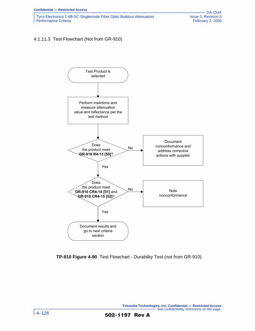
Confidential — Restricted Access
Tyco Electronics 1-dB SC Singlemode Fiber Optic Buildout Attenuators Issue 1, Revision 5Performance Criteria February 3, 2005
DA-1544
4.1.11.3 Test Flowchart (Not from GR-910)
TP-910 Figure 4-90 Test Flowchart - Durability Test (not from GR-910)
Document results andgo to next criteria
section
Test Product isselected
Perform insertions andmeasure attenuation
value and reflectance per the test method
Documentnonconformance and
address correctiveactions with supplier
No
Yes
Notenonconformance
No
Does the product meet
GR-910 R4-13 [50]?
Yes
Doesthe product meet
GR-910 CR4-14 [51] and GR-910 CR4-15 [52]?
�������� �� 4–126
Telcordia Technologies, Inc. Confidential — Restricted Access See confidentiality restrictions on title page.

Confidential — Restricted Access
Issue 1, Revision 5 Tyco Electronics 1-dB SC Singlemode Fiber Optic Buildout AttenuatorsFebruary 3, 2005 Performance Criteria
DA-1544
4.1.11.4 Test Configuration and Conditions (not from GR-910)
This test shall apply to connector receptacles, optical pad type attenuators, and patchcord type attenuators with connectorized pigtails. Attenuator test samples are to be subjected to the durability test procedure per Section 4.4.3.7 of GR-326-CORE.
Both connector interfaces of a connector receptacle or optical pad type attenuator are reconnected for 200 cycles. The attenuator shall be cleaned according to the supplier’s instructions. Connectors are to be cleaned in accordance with the procedure in Section 4.4.3.7 of GR-326-CORE.
Variable attenuators are to have their attenuation setting changed from the zero dB setting to their maximum setting and back, for a minimum of 200 times.
For fixed attenuators the attenuation value and reflectance are to be measured for each reconnection. The criteria in Section 4.2.2 and Section 4.2.5 are applied only to measurements made immediately after the cleaning operation. The results of all measurements will be reported.
For variable attenuators the attenuation value and reflectance are measured and reported after each excursion at their minimum and maximum attenuation setting. The criteria in Section 4.2.2 and Section 4.2.5 apply to each measurement.
Optical Measurements
For each test, compliance against the change in attenuation criteria is determined by measuring the attenuation as described in Section 5.2.2, or measure the optical transmittance and calculate the attenuation per FOTP-20, during or after each test. The compliance against the reflectance criteria is determined by measuring reflectance per FOTP-107, during or after each test. Visual and mechanical inspection should follow FOTP-13.
The operating and non-operating environmental criteria require monitoring during
testing. This can be accomplished using a Transmission Measurement Facility shown in TP-910 Figure 4-91, or another comparable system.
�������� �� 4–127
Telcordia Technologies, Inc. Confidential — Restricted Access See confidentiality restrictions on title page.

Confidential — Restricted Access
Tyco Electronics 1-dB SC Singlemode Fiber Optic Buildout Attenuators Issue 1, Revision 5Performance Criteria February 3, 2005
DA-1544
In accordance with Verizon requirements, this facility is equipped to make measurements at four wavelengths, 1310 nm, 1490 nm, 1550 nm and 1625 nm, accurate to ±0.05 dB for transmittance and ±1 dB for reflectance down to –60 dB. While this measurement system is recommended, other configurations capable of meeting the relevant measurement requirements are acceptable. For attenuators in which the leads were connectorized by the supplier, the connectors and leads should be inside the test chamber to check for fiber pistoning. This may result in additional measurement uncertainty attributable to variations in connector loss. The measurement facility functions as follows: Switch 3 selects light from one of four laser sources emitting near λ1 = 1310 nm, λ2 = 1490 nm, λ3 = 1550 nm or λ4 = 1625 nm. The Device Under Test (DUT) is fusion spliced between the source switch (Switch 1) and the detector switch (Switch 2). The source switch is used to launch light into any of the devices under test. The detector switch connects any DUT to the power meter, measuring transmitted power and reflected power. The Coupler directs the optical power reflected by the DUT to port (r) on Switch 2 for detection. A reference fiber, located at port (m) of Switch 1 and 2, is used to correct for variations in source power over time. A reflectance reference (suggested value is −60 ±1 dB) is located at port (r) of Switch 1, and is used to calculate reflectance from the measured optical power. Insertion loss is calculated by subtracting the power transmitted through the reference fiber from the power transmitted through the DUT. Reflectance is calculated by subtracting the power reflected by the reflectance reference from the power reflected by the DUT. All other switch ports are dedicated to DUTs. The Switches, Power Meter and Environmental Chambers are computer controlled via GPIB interface.
Laser sources are preferred over LEDs because source coherence affects both the DUT reflectance, and the loss of the switches. Fusion splices are recommended for their low loss and low reflectance. To obtain accurate reflectance measurements, all components in the measurement facility, including the power meter, splices and
TP-910 Figure 4-91 Transmission Measurement Facility
Source
�������� �� 4–128
Telcordia Technologies, Inc. Confidential — Restricted Access See confidentiality restrictions on title page.

Confidential — Restricted Access
Issue 1, Revision 5 Tyco Electronics 1-dB SC Singlemode Fiber Optic Buildout AttenuatorsFebruary 3, 2005 Performance Criteria
DA-1544
switches, should have a reflectance of ≤ −65 dB. The Coupler should have a directivity of ≥ 70 dB. Mode filters between the splices and DUT ensure single-mode transmission. A 2-meter length of the jumper cable will be a sufficient mode filter, provided that the cable conforms to the requirements of GR-409-CORE and there are at least two 360° loops in the 2 meter length. Refer to GR-326-CORE for additional details regarding measurement of loss and reflectance using the Transmission Measurement Facility.
4.1.11.5 Test Apparatus (not from GR-910)
4.1.11.6 Summary of Test Results (not from GR-910)
Conformance/Nonconformance
All of the eleven test samples conformed to the less stringent criteria in Section 4.1.11.1 of this document.
However, as shown in TP-910 Figure 4-92, the change in attenuation of sample i.l.05 at the 1490 nm wavelength did not conform to while i.l.04 at the 1310 nm and 1550 nm wavelengths, i.l.05 at the 1310 nm and 1550 nm wavelengths, i.l.08 at the 1550 nm wavelength and i.l.10 at the 1310 nm wavelength showed borderline performance to the more stringent criteria of GR-910 CR4-21 [58] which states
Description Supplier ModelCalibration Cycle
Calibration Due Date.
Optical Multimeter Frame
HP 8153A - n.a.
Optical Sensor HP 81532A 12 months -
Laser Source (dual wl)
HP 81554SM 12 months -
90/10% Coupler - -
Reflectance Standard
- -
Optical Switch JDS SC95B5-00NC
n.a.
Optical Switch JDS SC95B5-00NC
n.a.
Optical Switch JDS SW1-25 CS n.a.
Connector Panel ADC NA 12 months -
Optical Tunable Light Source
Agilent 8164A 12 months -
Sensor for tunable multimeter
Agilent 81640A 12 months -
�������� �� 4–129
Telcordia Technologies, Inc. Confidential — Restricted Access See confidentiality restrictions on title page.

Confidential — Restricted Access
Tyco Electronics 1-dB SC Singlemode Fiber Optic Buildout Attenuators Issue 1, Revision 5Performance Criteria February 3, 2005
DA-1544
that for all digital applications the maximum or minimum change in attenuation before, during, or after, any or all environmental or mechanical tests shall be ≤ 0.5 dB or ≤ 0.15A, whichever is less. Sample i.l.05 showed a change in attenuation of 0.23 ±0.05 dB at the 1490 nm wavelength.
Also shown in TP-910 Figure 4-92, the change in attenuation of samples i.l.04 at the 1310 nm and 1550 nm wavelengths, i.l.05 at the 1310 nm, 1490 nm and 1550 nm wavelengths, i.l.08 at the 1550 nm wavelength and i.l.10 at the 1310 nm wavelength did not conform to, while samples i.l.04 at the 1490 nm wavelength, i.l.06 at the 1310 nm and 1490 nm wavelengths, i.l.07 at the 1625 nm wavelength, i.l.08 at the 1490 nm wavelength, i.l.09 at the 1310 nm wavelength, i.l.10 at the 1625 nm wavelength and i.l.11 at the 1490 nm wavelength showed borderline performance to the more stringent criteria of GR-910 CR4-22 [59] which states that for all AM video applications the maximum or minimum change in attenuation before, during, or after, any or all environmental or mechanical tests shall be ≤ 0.5 dB or ≤ 0.10A, whichever is less. Sample i.l.04 showed a change in attenuation of 0.17 ±0.05 dB at the 1310 nm wavelength and 0.18 ±0.05 dB at the 1550 nm wavelength. Sample i.l.05 showed a change in attenuation of 0.17 ±0.05 dB at the 1310 nm wavelength, 0.23 ±0.05 dB at the 1490 nm wavelength and 0.16 ±0.05 dB at the 1550 nm wavelength. Sample i.l.08 showed a change in attenuation of 0.17 ±0.05 dB at the 1550 nm wavelength. Sample i.l.10 showed a change in attenuation of 0.18 ±0.05 dB at the 1310 nm wavelength.
As shown in TP-910 Figure 4-93, the insertion loss of samples i.l.01 at the 1490 nm, 1550 nm and 1625 nm wavelengths, i.l.03 at the 1310 nm, 1490 nm, 1550 nm and 1625 nm wavelengths, i.l.04 at the 1310 nm, 1490 nm, 1550 nm and 1625 nm wavelength, i.l.05 at the 1490 nm wavelength, i.l.06 at the 1490 nm wavelength, i.l.07 at the 1310 nm wavelength, i.l.08 at the 1310 nm, 1490 nm and 1550 nm wavelengths, i.l.09 at the 1310 nm, 1490 nm, 1550 nm and 1625 nm wavelengths and i.l.11 at the 1490 nm wavelength did not conform to, while samples i.l.05 at the 1310 nm wavelength, i.l.07 at the 1625 nm wavelength, i.l.08 at the 1625 nm wavelength, i.l.10 at the 1310 nm wavelength and i.l.11 at the 1550 nm wavelength showed borderline performance to the more stringent criteria of GR-910 CR4-23 [60] which states that for attenuators intended for use in digital applications, the attenuation tolerance shall not exceed ±0.15V. Sample i.l.01 showed a maximum insertion loss of 1.29 ±0.05 dB at the 1490 nm wavelength, 1.26 ±0.05 dB at the 1550 nm wavelength and 1.33 ±0.05 dB at the 1625 nm wavelength. Sample i.l.03 showed a maximum insertion loss of 1.31 ±0.05 dB at the 1310 nm wavelength, 1.23 ±0.05 dB at the 1490 nm wavelength, 1.32 ±0.05 dB at the 1550 nm wavelength and 1.33 ±0.05 dB at the 1625 nm wavelength. Sample i.l.04 showed a maximum insertion loss of 1.24 ±0.05 dB at the 1310 nm wavelength, 1.31 ±0.05 dB at the 1490 nm wavelength, 1.42 ±0.05 dB at the 1550 nm wavelength and 1.43 ±0.05 dB at the 1625 nm wavelength. Sample i.l.05 showed a maximum insertion loss of 1.30 ±0.05 dB at the 1490 nm wavelength. Sample i.l.06 showed a maximum insertion loss of 1.28 ±0.05 dB at the 1490 nm wavelength. Sample i.l.07 showed a maximum insertion loss of 1.21 ±0.05 dB at the 1310 nm wavelength.
�������� �� 4–130
Telcordia Technologies, Inc. Confidential — Restricted Access See confidentiality restrictions on title page.

Confidential — Restricted Access
Issue 1, Revision 5 Tyco Electronics 1-dB SC Singlemode Fiber Optic Buildout AttenuatorsFebruary 3, 2005 Performance Criteria
DA-1544
Sample i.l.08 showed a maximum insertion loss of 1.28 ±0.05 dB at the 1310 nm wavelength, 1.24 ±0.05 dB at the 1490 nm wavelength and 1.33 ±0.05 dB at the 1550 nm wavelength. Sample i.l.09 showed a maximum insertion loss of 1.36 ±0.05 dB at the 1310 nm wavelength, 1.27 ±0.05 dB at the 1490 nm wavelength, 1.39 ±0.05 dB at the 1550 nm wavelength and 1.35 ±0.05 dB at the 1625 nm wavelength. Sample i.l.11 showed a maximum insertion loss of 1.31 ±0.05 dB at the 1490 nm wavelength.
Also shown in TP-910 Figure 4-93, the insertion loss of samples i.l.01 at the 1490 nm, 1550 nm and 1625 nm wavelengths, i.l.03 at the 1310 nm, 1490 nm, 1550 nm and 1625 nm wavelengths, i.l.04 at the 1310 nm, 1490 nm, 1550 nm and 1625 nm wavelength, i.l.05 at the 1310 nm and 1490 nm wavelengths, i.l.06 at the 1490 nm wavelength, i.l.07 at the 1310 nm and 1625 nm wavelengths, i.l.08 at the 1310 nm, 1490 nm, 1550 nm and 1625 nm wavelengths, i.l.09 at the 1310 nm, 1490 nm, 1550 nm and 1625 nm wavelengths and i.l.11 at the 1490 nm and 1550 nm wavelengths did not conform to, while samples i.l.01 at the 1310 nm wavelength, i.l.02 at the 1310 nm and 1625 nm wavelengths, i.l.05 at the 1550 nm wavelength, i.l.06 at the 1625 nm wavelength, i.l.10 at the 1310 nm wavelength and i.l.11 at the 1625 nm wavelength showed borderline performance to the more stringent criteria of GR-910 CR4-24 [61] which states that for attenuators intended for use in AM video applications, the attenuation tolerance shall not exceed ±0.10V. Sample i.l.01 showed a maximum insertion loss of 1.29 ±0.05 dB at the 1490 nm wavelength, 1.26 ±0.05 dB at the 1550 nm wavelength and 1.33 ±0.05 dB at the 1625 nm wavelength. Sample i.l.03 showed a maximum insertion loss of 1.31 ±0.05 dB at the 1310 nm wavelength, 1.23 ±0.05 dB at the 1490 nm wavelength, 1.32 ±0.05 dB at the 1550 nm wavelength and 1.33 ±0.05 dB at the 1625 nm wavelength. Sample i.l.04 showed a maximum insertion loss of 1.24 ±0.05 dB at the 1310 nm wavelength, 1.31 ±0.05 dB at the 1490 nm wavelength, 1.42 ±0.05 dB at the 1550 nm wavelength and 1.43 ±0.05 dB at the 1625 nm wavelength. Sample i.l.05 showed a maximum insertion loss of 1.16 ±0.05 dB at the 1310 nm wavelength and 1.30 ±0.05 dB at the 1490 nm wavelength. Sample i.l.06 showed a maximum insertion loss of 1.28 ±0.05 dB at the 1490 nm wavelength. Sample i.l.07 showed a maximum insertion loss of 1.21 ±0.05 dB at the 1310 nm wavelength and 1.16 ±0.05 dB at the 1625 nm wavelength. Sample i.l.08 showed a maximum insertion loss of 1.28 ±0.05 dB at the 1310 nm wavelength, 1.24 ±0.05 dB at the 1490 nm, 1.33 ±0.05 dB at the 1550 nm wavelength and 1.16 ±0.05 dB at the 1625 nm wavelength. Sample i.l.09 showed a maximum insertion loss of 1.36 ±0.05 dB at the 1310 nm wavelength, 1.27 ±0.05 dB at the 1490 nm wavelength, 1.39 ±0.05 dB at the 1550 nm wavelength and 1.35 ±0.05 dB at the 1625 nm wavelength. Sample i.l.11 showed a maximum insertion loss of 1.31 ±0.05 dB at the 1490 nm wavelength and 1.19 ±0.05 dB at the 1550 nm wavelength.
In addition, as shown in TP-910 Figure 4-94, conformance to GR-910 CO4-32 [69] which states that the maximum reflectance for attenuators intended for use in AM-VSB systems should be ≤ –65 dB over the entire bandpass of GR-910 CR4-20 [57] and operating temperature range of –40°C to +75°C was not met. This is a conditional objective and it is up to the end user to determine the significance of this nonconformance issue. Conformance is based on
�������� �� 4–131
Telcordia Technologies, Inc. Confidential — Restricted Access See confidentiality restrictions on title page.

Confidential — Restricted Access
Tyco Electronics 1-dB SC Singlemode Fiber Optic Buildout Attenuators Issue 1, Revision 5Performance Criteria February 3, 2005
DA-1544
demonstration of no physical damage to the product under test, as well as the optical criteria described in Section 4.2.
Nonconforming deviations to GR-910 CO4-32 [69] were noted in testing.
Sample Size
Eleven samples, in accordance with 20% LTPD specified in GR-910-CORE, Issue 2, were used in the test program. In addition, eleven samples were added to serve as hot spares for replacing sample(s) with nonconformance identified in the test program.
Failure History
Not applicable.
Disposition of Nonconformance
Not applicable.
Test Data
The following charts represent the entire set of samples tested. This includes a total of eleven (11) samples of buildout attenuators (BOA). TP-910 Figure 4-92 presents change-in-attenuation measurements after the Durability test for all of the eleven test samples at 1310 nm, 1490 nm, 1550 nm and 1625 nm. TP-910 Figure 4-93 presents insertion loss measurements (including connection losses of about 0.5 dB) after the Durability test for all of the eleven test samples at 1310 nm, 1490 nm, 1550 nm and 1625 nm. TP-910 Figure 4-94 presents the reflectance measurements after the Durability test for all of the eleven test samples at 1310 nm, 1490 nm, 1550 nm and 1625 nm.
�������� �� 4–132
Telcordia Technologies, Inc. Confidential — Restricted Access See confidentiality restrictions on title page.

Confidential — Restricted Access
Issue 1, Revision 5 Tyco Electronics 1-dB SC Singlemode Fiber Optic Buildout AttenuatorsFebruary 3, 2005 Performance Criteria
DA-1544
TP-910 Figure 4-92 Change in Attenuation at 1310 nm, 1490 nm, 1550 nm and 1625 nm after Durability test
TP-910 Figure 4-93 Insertion Loss at 1310 nm, 1490 nm, 1550 nm and 1625 nm after Durability test
Tyco Electronics, 1-dB Attenuators, After Durability Test
i.l.11i.l.10i.l.09i.l.08i.l.07i.l.06i.l.05i.l.04i.l.03i.l.02i.l.01-0.6
-0.4
-0.2
0.0
0.2
0.4
0.6
i.l.0 1 i.l.0 2 i.l.0 3 i.l.0 4 i.l.0 5 i.l.0 6 i.l.0 7 i.l.0 8 i.l.0 9 i.l.1 0 i.l.1 1
Sample #
Chan
ge in
Atte
nuat
ion
(dB)
1310 nm1490 nm1550 nm1625 nm
AM Video
Digital
+/- 0.5 dB
Tyco Electronics, 1-dB Attenuators, After Durability Test
0.40
0.60
0.80
1.00
1.20
1.40
1.60
i.l.01 i.l.02 i.l.03 i.l.04 i.l.05 i.l.06 i.l.07 i.l.08 i.l.09 i.l.10 i.l.11Sample #
Inse
rtion
Los
s (d
B)
1310 nm1490 nm1550 nm1625 nm
AM Video
Digital
+/- 0.5 dB
�������� �� 4–133
Telcordia Technologies, Inc. Confidential — Restricted Access See confidentiality restrictions on title page.
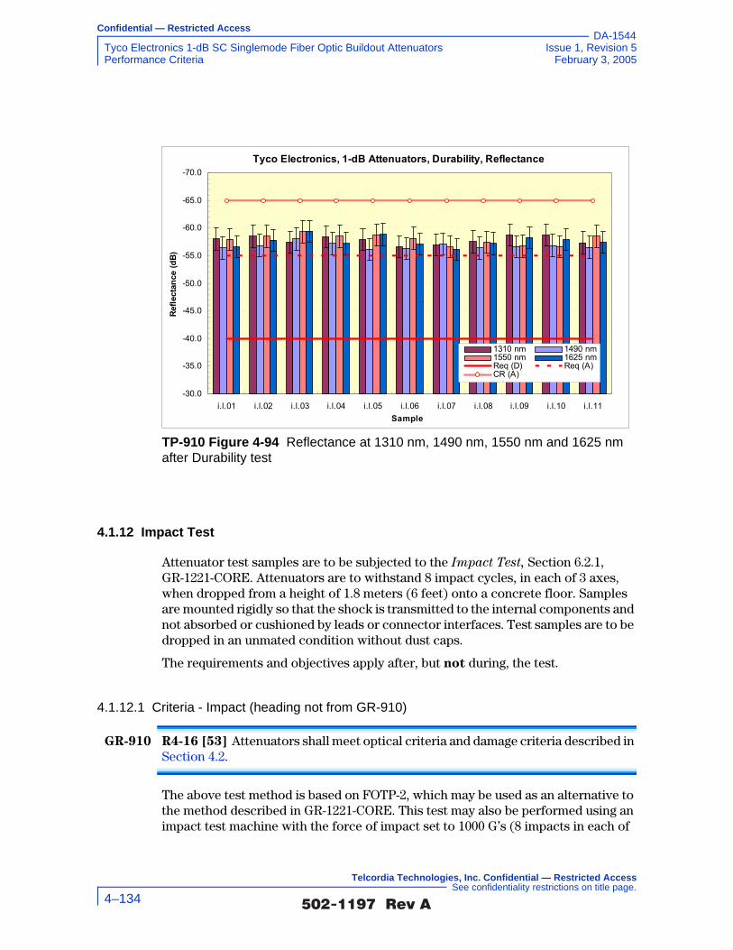
Confidential — Restricted Access
Tyco Electronics 1-dB SC Singlemode Fiber Optic Buildout Attenuators Issue 1, Revision 5Performance Criteria February 3, 2005
DA-1544
4.1.12 Impact Test
Attenuator test samples are to be subjected to the Impact Test, Section 6.2.1, GR-1221-CORE. Attenuators are to withstand 8 impact cycles, in each of 3 axes, when dropped from a height of 1.8 meters (6 feet) onto a concrete floor. Samples are mounted rigidly so that the shock is transmitted to the internal components and not absorbed or cushioned by leads or connector interfaces. Test samples are to be dropped in an unmated condition without dust caps.
The requirements and objectives apply after, but not during, the test.
4.1.12.1 Criteria - Impact (heading not from GR-910)
GR-910 R4-16 [53] Attenuators shall meet optical criteria and damage criteria described in Section 4.2.
The above test method is based on FOTP-2, which may be used as an alternative to the method described in GR-1221-CORE. This test may also be performed using an impact test machine with the force of impact set to 1000 G’s (8 impacts in each of
TP-910 Figure 4-94 Reflectance at 1310 nm, 1490 nm, 1550 nm and 1625 nm after Durability test
Tyco Electronics, 1-dB Attenuators, Durability, Reflectance-70.0
-65.0
-60.0
-55.0
-50.0
-45.0
-40.0
-35.0
-30.0i.l.01 i.l.02 i.l.03 i.l.04 i.l.05 i.l.06 i.l.07 i.l.08 i.l.09 i.l.10 i.l.11
Sample
Refle
ctan
ce (d
B)
1310 nm 1490 nm1550 nm 1625 nmReq (D) Req (A)CR (A)
`
�������� �� 4–134
Telcordia Technologies, Inc. Confidential — Restricted Access See confidentiality restrictions on title page.
Confidential — Restricted Access
Issue 1, Revision 5 Tyco Electronics 1-dB SC Singlemode Fiber Optic Buildout AttenuatorsFebruary 3, 2005 Performance Criteria
DA-1544
3 axes), per MIL 202F, Method 213B- 1/2 sine Shock. Duration is 0.5 ms by definition.
4.1.12.2 Test Method (not from GR-910)
1. Verify that the lab ambient conditions are in the range of 23 ±5°C, and 30 to 70% relative humidity
2. Warm up/prepare and stabilize test equipment per manufacturers instructions, up to 1 hour
3. Verify that the test equipment to be used meets calibration requirements
4. Review manufacturer instructions/procedures for product under test, to assure product usage/configuration is appropriate
5. Inspect physical condition of product under test
6. Clean connection points and perform initial optical measurements
7. Prepare test setup as defined in EIA/TIA-455-2A for light service applications with drop height of six feet
8. Verify that the product under test is rigidly mounted for the X-axis orientation
9. Execute five (5) sets of eight (8) drops for the X-axis orientation
10. Perform final optical power readings and record data
11. Repeat five sets of eight drops each in Y-axis, and then the Z-axis
12. Perform final optical measurements after completion of each axis tests
13. Inspect product under test for any physical damage and record observations
14. Record conformance status. If non-conforming, notify supplier.
�������� �� 4–135
Telcordia Technologies, Inc. Confidential — Restricted Access See confidentiality restrictions on title page.

Confidential — Restricted Access
Tyco Electronics 1-dB SC Singlemode Fiber Optic Buildout Attenuators Issue 1, Revision 5Performance Criteria February 3, 2005
DA-1544
4.1.12.3 Test Flowchart (not from GR-910)
TP-910 Figure 4-95 Test Flowchart - Impact Test (not from GR-910)
Verify lab ambients of23C +/-5 and 30-
70%RH
Prepare/Warm-up testequipment permanufacturers
instructions
Verify test equipmentcalibration
Verify product undertest configured per
manufacturerinstructions
Verify that samples arerigidly mounted for X-
axis impacts
Prepare test setup perEIA/TIA-455-2A using
a drop height of six feet
No MechanicalDamage and opticalreadings in spec?
Recordfindings andfollow non-conforming
process
Recordfindings and
completereport section
Test Complete
Yes
No
Execute test - 8 dropsfor the X-axis per
cycle, 5 cycles totalInspect product undertest physical condition
Clean connectionpoints and perform
initial opticalmeasurements
Perform final opticalmeasurements and
inspect for any physicaldamage
Repeat tests for Y-Axisand Z-Axis
�������� �� 4–136
Telcordia Technologies, Inc. Confidential — Restricted Access See confidentiality restrictions on title page.

Confidential — Restricted Access
Issue 1, Revision 5 Tyco Electronics 1-dB SC Singlemode Fiber Optic Buildout AttenuatorsFebruary 3, 2005 Performance Criteria
DA-1544
4.1.12.4 Test Configuration and Conditions (not from GR-910)
This test is to be performed according to GR-1221-CORE, Section 6.2.1, Impact Test, which is based on FOTP-2 for “Light Service Application.” Attenuators are to withstand 8 impact cycles, from each of three mutually perpendicular axes, when dropped from a height of 1.8 meters (6 feet) onto a concrete floor.
The attenuators shall be dropped in an unmated condition without protective caps. Samples are mounted rigidly so that the shock is transmitted to the internal components and not absorbed or cushioned by the leads. A suggested method for performing this test is to place the test sample inside a container filled with a rigid packing material (such as sand or small glass beads) so that the sample does not shift or bounce around when the container is dropped. In this way, the impact shock is not absorbed by an elastic packing material, but is fully transmitted to the internal components. Samples with leads may be protected from breakage if they are coiled and tied. The connector plug/ferrule may be protected with a cap that does not impede the impact force.
This test may also be performed using an impact test machine with the force of impact set to 1000 G's.
After testing, each attenuator is to be carefully examined for evidence of physical damage as described in Section 4.2.8. The maximum change in attenuation and reflectance is the difference in measurements taken before and after the test and is to be compared against the requirements and objectives specified in Section 4.2.2 and Section 4.2.5.
4.1.12.5 Test Apparatus (not from GR-910)
Description Supplier ModelCalibration Cycle
Calibration Due Date.
Optical Multimeter Frame
HP 8153A - n.a.
Optical Sensor HP 81532A 12 months -
Laser Source (dual wl)
HP 81554SM 12 months -
90/10% Coupler - -
Reflectance Standard
- -
Optical Switch JDS SC95B5-00NC
n.a.
Optical Switch JDS SC95B5-00NC
n.a.
Optical Switch JDS SW1-25 CS n.a.
�������� �� 4–137
Telcordia Technologies, Inc. Confidential — Restricted Access See confidentiality restrictions on title page.

Confidential — Restricted Access
Tyco Electronics 1-dB SC Singlemode Fiber Optic Buildout Attenuators Issue 1, Revision 5Performance Criteria February 3, 2005
DA-1544
4.1.12.6 Summary of Test Results (not from GR-910)
Conformance/Nonconformance
All of the eleven test samples conformed to the less stringent criteria in Section 4.1.12.1 of this document.
However, as shown in TP-910 Figure 4-96, the change in attenuation of samples i.l.01 at the 1625 nm wavelength, i.l.03 at the 1625 nm wavelength, i.l.05 at the 1490 nm wavelength, i.l.07 at the 1625 nm wavelength, i.l.08 at the 1550 nm wavelength, i.l.09 at the 1625 nm wavelength and i.l.10 at the 1625 nm wavelength showed borderline performance to the more stringent criteria of GR-910 CR4-21 [58] which states that for all digital applications the maximum or minimum change in attenuation before, during, or after, any or all environmental or mechanical tests shall be ≤ 0.5 dB or ≤ 0.15A, whichever is less.
Also shown in TP-910 Figure 4-96, the change in attenuation of samples i.l.01 at the 1625 nm wavelength, i.l.03 at the 1625 nm wavelength, i.l.05 at the 1490 nm wavelength, i.l.07 at the 1625 nm wavelength, i.l.08 at the 1550 nm wavelength, i.l.09 at the 1625 nm wavelength and i.l.10 at the 1625 nm wavelength did not conform to, while samples i.l.05 at the 1310 nm and 1550 nm wavelengths and i.l.11 at the 1490 nm wavelength showed borderline performance to the more stringent criteria of GR-910 CR4-22 [59] which states that for all AM video applications the maximum or minimum change in attenuation before, during, or after, any or all environmental or mechanical tests shall be ≤ 0.5 dB or ≤ 0.10A, whichever is less. Sample i.l.01 showed a change in attenuation of 0.18 ±0.05 dB at the 1625 nm wavelength. Sample i.l.03 showed a change in attenuation of 0.19 ±0.05 dB at the 1625 nm wavelength. Sample i.l.05 showed a change in attenuation of 0.18 ±0.05 dB at the 1490 nm wavelength. Sample i.l.07 showed a change in attenuation of 0.17 ±0.05 dB at the 1625 nm wavelength. Sample i.l.08 showed a change in attenuation of 0.16 ±0.05 dB at the 1550 nm wavelength. Sample i.l.09 showed a change in attenuation of 0.16 ±0.05 dB at the 1625 nm wavelength. Sample i.l.10 showed a change in attenuation of 0.20 ±0.05 dB at the 1625 nm wavelength.
As shown in TP-910 Figure 4-97, the insertion loss of samples i.l.01 at the 1490 nm, 1550 nm and 1625 nm wavelengths, i.l.02 at the 1625 nm wavelength, i.l.03 at the 1310 nm, 1490 nm, 1550 nm and 1625 nm wavelengths, i.l.04 at the 1490 nm, 1550 nm and 1625 nm wavelength, i.l.07 at the 1310 nm and 1625 nm wavelengths, i.l.08 at the 1310 nm and 1625 nm wavelengths, i.l.09 at the 1310 nm, 1490 nm, 1550 nm and
Impact Tester In-house NA 12 months -
Optical Tunable Light Source
Agilent 8164A 12 months -
Sensor for tunable multimeter
Agilent 81640A 12 months -
Description Supplier ModelCalibration Cycle
Calibration Due Date.
�������� �� 4–138
Telcordia Technologies, Inc. Confidential — Restricted Access See confidentiality restrictions on title page.

Confidential — Restricted Access
Issue 1, Revision 5 Tyco Electronics 1-dB SC Singlemode Fiber Optic Buildout AttenuatorsFebruary 3, 2005 Performance Criteria
DA-1544
1625 nm wavelengths and i.l.11 at the 1490 nm and 1550 nm wavelengths did not conform to, while samples i.l.01 at the 1310 nm wavelength, i.l.04 at the 1310 nm wavelength, i.l.06 at the 1490 nm and 1625 nm wavelengths, i.l.08 at the 1490 nm and 1550 nm wavelengths, i.l.10 at the 1490 nm wavelength and i.l.11 at the 1625 nm wavelength showed borderline performance to the more stringent criteria of GR-910 CR4-23 [60] which states that for attenuators intended for use in digital applications, the attenuation tolerance shall not exceed ±0.15V. Sample i.l.01 showed a maximum insertion loss of 1.34 ±0.05 dB at the 1490 nm wavelength, 1.28 ±0.05 dB at the 1550 nm wavelength and 1.40 ±0.05 dB at the 1625 nm wavelength. Sample i.l.02 showed a maximum insertion loss of 1.21 ±0.05 dB at the 1625 nm wavelength. Sample i.l.03 showed a maximum insertion loss of 1.36 ±0.05 dB at the 1310 nm wavelength, 1.29 ±0.05 dB at the 1490 nm wavelength, 1.37 ±0.05 dB at the 1550 nm wavelength and 1.42 ±0.05 dB at the 1625 nm wavelength. Sample i.l.04 showed a maximum insertion loss of 1.28 ±0.05 dB at the 1490 nm wavelength, 1.39 ±0.05 dB at the 1550 nm wavelength and 1.46 ±0.05 dB at the 1625 nm wavelength. Sample i.l.07 showed a maximum insertion loss of 1.35 ±0.05 dB at the 1310 nm wavelength and 1.33 ±0.05 dB at the 1625 nm wavelength. Sample i.l.08 showed a maximum insertion loss of 1.27 ±0.05 dB at the 1310 nm wavelength and 1.21 ±0.05 dB at the 1625 nm wavelength. Sample i.l.09 showed a maximum insertion loss of 1.42 ±0.05 dB at the 1310 nm wavelength, 1.29 ±0.05 dB at the 1490 nm wavelength, 1.43 ±0.05 dB at the 1550 nm wavelength and 1.44 ±0.05 dB at the 1625 nm wavelength. Sample i.l.11 showed a maximum insertion loss of 1.29 ±0.05 dB at the 1490 nm wavelength and 1.23 ±0.05 dB at the 1550 nm wavelength.
Also shown in TP-910 Figure 4-97, the insertion loss of samples i.l.01 at the 1310 nm, 1490 nm, 1550 nm and 1625 nm wavelengths, i.l.02 at the 1625 nm wavelength, i.l.03 at the 1310 nm, 1490 nm, 1550 nm and 1625 nm wavelengths, i.l.04 at the 1490 nm, 1550 nm and 1625 nm wavelength, i.l.06 at the 1490 nm and 1625 nm wavelengths, i.l.07 at the 1310 nm and 1625 nm wavelengths, i.l.08 at the 1310 nm, 1490 nm, 1550 nm and 1625 nm wavelengths, i.l.09 at the 1310 nm, 1490 nm, 1550 nm and 1625 nm wavelengths, i.l.10 at the 1490 nm wavelength and i.l.11 at the 1490 nm, 1550 nm and 1625 nm wavelengths did not conform to, while samples i.l.02 at the 1310 nm wavelength, i.l.05 at the 1490 nm wavelength, i.l.07 at the 1550 nm wavelength and i.l.10 at the 1625 nm wavelength showed borderline performance to the more stringent criteria of GR-910 CR4-24 [61] which states that for attenuators intended for use in AM video applications, the attenuation tolerance shall not exceed ±0.10V. Sample i.l.01 showed a maximum insertion loss of 1.16 ±0.05 dB at the 1310 nm wavelength, 1.34 ±0.05 dB at the 1490 nm wavelength, 1.28 ±0.05 dB at the 1550 nm wavelength and 1.40 ±0.05 dB at the 1625 nm wavelength. Sample i.l.02 showed a maximum insertion loss of 1.21 ±0.05 dB at the 1625 nm wavelength. Sample i.l.03 showed a maximum insertion loss of 1.36 ±0.05 dB at the 1310 nm wavelength, 1.29 ±0.05 dB at the 1490 nm wavelength, 1.37 ±0.05 dB at the 1550 nm wavelength and 1.42 ±0.05 dB at the 1625 nm wavelength. Sample i.l.04 showed a maximum insertion loss of 1.28 ±0.05 dB at the 1490 nm wavelength, 1.39 ±0.05 dB at the 1550 nm wavelength and 1.46 ±0.05 dB at the 1625 nm wavelength. Sample i.l.06 showed a maximum insertion loss of
�������� �� 4–139
Telcordia Technologies, Inc. Confidential — Restricted Access See confidentiality restrictions on title page.

Confidential — Restricted Access
Tyco Electronics 1-dB SC Singlemode Fiber Optic Buildout Attenuators Issue 1, Revision 5Performance Criteria February 3, 2005
DA-1544
1.18 ±0.05 dB at the 1490 nm wavelength and 1.20 ±0.05 dB at the 1625 nm wavelength. Sample i.l.07 showed a maximum insertion loss of 1.35 ±0.05 dB at the 1310 nm wavelength and 1.33 ±0.05 dB at the 1625 nm wavelength. Sample i.l.08 showed a maximum insertion loss of 1.27 ±0.05 dB at the 1310 nm wavelength, 1.17 ±0.05 dB at the 1490 nm wavelength, 1.17 ±0.05 dB at the 1550 nm wavelength and 1.21 ±0.05 dB at the 1625 nm wavelength. Sample i.l.09 showed a maximum insertion loss of 1.42 ±0.05 dB at the 1310 nm wavelength, 1.29 ±0.05 dB at the 1490 nm wavelength, 1.43 ±0.05 dB at the 1550 nm wavelength and 1.44 ±0.05 dB at the 1625 nm wavelength. Sample i.l.10 showed a maximum insertion loss of 1.18 ±0.05 dB at the 1490 nm wavelength. Sample i.l.11 showed a maximum insertion loss of 1.29 ±0.05 dB at the 1490 nm wavelength, 1.23 ±0.05 dB at the 1550 nm wavelength and 1.20 ±0.05 dB at the 1625 nm wavelength.
In addition, as shown in TP-910 Figure 4-98, samples i.l.07 at the 1625 nm wavelength and i.l.08 at the 1490 nm wavelength showed borderline performance to GR-910 CR4-31 [68] which states that the maximum reflectance for attenuators intended for use in AM-VSB systems shall be ≤ –55 dB over the entire bandpass of GR-910 CR4-20 [57] and operating temperature range of –40°C to +75°C.
Furthermore, as shown in TP-910 Figure 4-98, conformance to GR-910 CO4-32 [69] which states that the maximum reflectance for attenuators intended for use in AM-VSB systems should be ≤ –65 dB over the entire bandpass of GR-910 CR4-20 [57] and operating temperature range of –40°C to +75°C was not met. This is a conditional objective and it is up to the end user to determine the significance of this nonconformance issue. Conformance is based on demonstration of no physical damage to the product under test, as well as the optical criteria described in Section 4.2.
Nonconforming deviations to GR-910 CO4-32 [69] were noted in testing.
Sample Size
Eleven samples, in accordance with 20% LTPD specified in GR-910-CORE, Issue 2, were used in the test program. In addition, eleven samples were added to serve as hot spares for replacing sample(s) with nonconformance identified in the test program.
Failure History
Not applicable.
Disposition of Nonconformance
Not applicable.
Test Data
The following charts represent the entire set of samples tested. This includes a total of eleven (11) samples of buildout attenuators (BOA). TP-910 Figure 4-96 presents change-in-attenuation measurements after the Impact test for all of the eleven test samples at 1310 nm, 1490 nm, 1550 nm and 1625 nm. TP-910 Figure 4-97 presents insertion loss measurements (including connection losses of about 0.5 dB) after the Impact test for all of the eleven test samples at 1310 nm, 1490 nm, 1550 nm and
�������� �� 4–140
Telcordia Technologies, Inc. Confidential — Restricted Access See confidentiality restrictions on title page.

Confidential — Restricted Access
Issue 1, Revision 5 Tyco Electronics 1-dB SC Singlemode Fiber Optic Buildout AttenuatorsFebruary 3, 2005 Performance Criteria
DA-1544
1625 nm. TP-910 Figure 4-98 presents the reflectance measurements after the Impact test for all of the eleven test samples at 1310 nm, 1490 nm, 1550 nm and 1625 nm.
TP-910 Figure 4-96 Change in Attenuation at 1310 nm, 1490 nm, 1550 nm and 1625 nm after Impact test
Tyco Electronics, 1-dB Attenuators, After Impact Test
i.l.11i.l.10i.l.09i.l.08i.l.07i.l.06i.l.05i.l.04i.l.03i.l.02i.l.01-0.6
-0.4
-0.2
0.0
0.2
0.4
0.6
i.l.0 1 i.l.0 2 i.l.0 3 i.l.0 4 i.l.0 5 i.l.0 6 i.l.0 7 i.l.0 8 i.l.0 9 i.l.1 0 i.l.1 1
Sample #
Chan
ge in
Atte
nuat
ion
(dB)
1310 nm1490 nm1550 nm1625 nm
AM Video
Digital
+/- 0.5 dB
�������� �� 4–141
Telcordia Technologies, Inc. Confidential — Restricted Access See confidentiality restrictions on title page.

Confidential — Restricted Access
Tyco Electronics 1-dB SC Singlemode Fiber Optic Buildout Attenuators Issue 1, Revision 5Performance Criteria February 3, 2005
DA-1544
TP-910 Figure 4-97 Insertion Loss at 1310 nm, 1490 nm, 1550 nm and 1625 nm after Impact test
TP-910 Figure 4-98 Reflectance at 1310 nm, 1490 nm, 1550 nm and 1625 nm after Impact test
Tyco Electronics, 1-dB Attenuators, After Impact Test
0.40
0.60
0.80
1.00
1.20
1.40
1.60
i.l.01 i.l.02 i.l.03 i.l.04 i.l.05 i.l.06 i.l.07 i.l.08 i.l.09 i.l.10 i.l.11Sample #
Inse
rtion
Los
s (d
B)
1310 nm1490 nm1550 nm1625 nm
AM Video
Digital
+/- 0.5 dB
Tyco Electronics, 1-dB Attenuators, Impact, Reflectance-70.0
-65.0
-60.0
-55.0
-50.0
-45.0
-40.0
-35.0
-30.0i.l.01 i.l.02 i.l.03 i.l.04 i.l.05 i.l.06 i.l.07 i.l.08 i.l.09 i.l.10 i.l.11
Sample
Refle
ctan
ce (d
B)
1310 nm 1490 nm1550 nm 1625 nmReq (D) Req (A)CR (A)
`
�������� �� 4–142
Telcordia Technologies, Inc. Confidential — Restricted Access See confidentiality restrictions on title page.

Confidential — Restricted Access
Issue 1, Revision 5 Tyco Electronics 1-dB SC Singlemode Fiber Optic Buildout AttenuatorsFebruary 3, 2005 Performance Criteria
DA-1544
4.2 Optical Criteria
The Optical Criteria addresses the required optical performance characteristics of attenuators. The wavelength ranges over which the attenuator must operate independently are addressed by the optical bandpass requirement. The attenuation tolerance requirement addresses the accuracy of attenuators marked in units of “dB”. The attenuation change requirement addresses the change in attenuation due to environmental or mechanical stress. The attenuation increments and range requirements specify the minimum incremental change of attenuation and the minimum range of fixed and variable attenuators. The optical power reflected back from an attenuator is addressed by the reflectance requirement. Finally, the variation of attenuation with changing incident light polarization orientation is addressed by the polarization-dependent loss criteria. All optical requirements shall be applied for both directions of light propagation (only one direction for single-mode to multimode attenuators that are non-reversible). The attenuation, A, is the ratio of optical power input to the attenuator, Pi, to the optical power output from the attenuator, Po, measured in units of dB.
The criteria is intended for attenuators used for digital transmission at bit-rates up to 10 Gb/s and for analog AM/Digital video transmission. Some of these optical criteria are separated into application specific conditional requirements (CRs) for digital transmission at bit-rates up to 10 Gb/s, and application specific CRs for analog AM/Digital video transmission. It is the responsibility of the user to select
the appropriate CR to invoke, based on the type of service to be supported.
A = 10 log (Pi / Po) (4-3)
4.2.1 Optical Bandpass
The optical bandpass is the wavelength range over which the applicable set of optical requirements are satisfied. An optical bandpass for an attenuator is bounded by two wavelength end points at which its transmission spectrum intercepts the required criteria.
4.2.1.1 Criteria - Optical Bandpass (heading not from GR-910)
GR-910 CR4-17 [54] For 1310/1550nm attenuators to be used for all digital applications except long-reach SONET, all optical requirements shall be met over the bandpass for both the 1310nm and the 1550nm regions specified in GR-910 Table 4-3, Column 2.
GR-910 CO4-18 [55] For 1310/1550nm attenuators to be used for all digital applications, all optical objectives should be met over the bandpass for both the 1310 nm and the 1550nm regions specified in GR-910 Table 4-3, Column 3.
�������� �� 4–143
Telcordia Technologies, Inc. Confidential — Restricted Access See confidentiality restrictions on title page.

Confidential — Restricted Access
Tyco Electronics 1-dB SC Singlemode Fiber Optic Buildout Attenuators Issue 1, Revision 5Performance Criteria February 3, 2005
DA-1544
GR-910 CR4-19 [56] For 1310/1550nm attenuators to be used for long-reach SONET only, all optical requirements shall be met over the bandpass specified in GR-910 Table 4-3, Column 4.
GR-910 CR4-20 [57] For all attenuators intended for use in AM-VSB video transmission, all optical requirements shall be met over the bandpass specified in GR-910 Table 4-3, Column 5.
The bandpasses shown in Columns 2 and 3 apply to attenuators used in all applications, including FITL and SONET short-reach (SR; having interconnect distances of ~ 2 km or more), intermediate-reach (IR; ~ 15 km or more), and long-reach (LR; ~ 40 km or more) systems. For attenuators, (GR-910 CR4-19 [56]) (in Column 4) applies to SONET LR and interoffice systems. For these applications,
the source wavelength must be selected to match this narrower bandpass. (GR-910 CR4-19 [56]) may not work for SONET SR and IR systems, nor for FITL
systems, since these systems may operate outside this narrow bandpass. (GR-910 CR4-20 [57]) (in Column 5) applies to all attenuators intended for use in AM-video applications. For video, the specific optical criteria in the 1310nm and 1550nm windows differ. Should more than one service need to be supported, then several bandpass criteria may apply. The user should select the widest applicable bandpass in either window.
Rationale: All attenuators must be of the wideband type, i.e., capable of
operation in both regions simultaneously, to accommodate future
upgrades. The bandpasses are derived from the attenuation characteristics
of single-mode fiber and the variations in transmitter central wavelength.
The bandpass values in GR-910 Table 4-3 are intended to make attenuators
reasonably transparent in the telecommunications network. The bandpass
requirement is consistent with optical interface requirements for FITL
(TA-NWT-000909) and SONET (GR-253-CORE). The video bandpass
criteria is derived from the standard emission wavelength range of video
laser transmitters and receivers.
GR-910 Table 4-3 Optical Bandpass Criteria
Wavelength DigitalLong Reach
SONETAM Video
1Region
(nm)
2(GR-910 CR4-
17 [54])
(nm)
3(GR-910 CO4-
18 [55])
(nm)
4(GR-910 CR4-19
[56])(nm)
5(GR-910 CR4-
20 [57])(nm)
1310 1260 –>1360 1260 –>1360 1280 –>1335 1290 –>1330
1550 1480 –>1580 1430 –>1580 1525 –>1575 1530 –>1570
�������� �� 4–144
Telcordia Technologies, Inc. Confidential — Restricted Access See confidentiality restrictions on title page.

Confidential — Restricted Access
Issue 1, Revision 5 Tyco Electronics 1-dB SC Singlemode Fiber Optic Buildout AttenuatorsFebruary 3, 2005 Performance Criteria
DA-1544
4.2.1.2 Test Method (not from GR-910)
1. Is the attenuator intended for use in multiple application environments? If so, determine from the product documentation the wavelength bands over which it is specified to operate. If not, go to the next test area.
2. Does the attenuator have connectorized pigtails for all fiber terminations? If it does not, fusion splice connectorized fiber pigtails to all DUT fiber leads. When possible, use fiber fanouts.
3. Clean all optical connectors prior to use following cleaning procedure A or B described in GR-326-CORE, Section 4.3.
The following cleaning procedure (Procedure A) shall be followed, unless the manufacturer of the DUT provides an alternative procedure (Procedure B).
a. If both plugs have been removed from the adapter, blow compressed gas through the adapter. If both plugs are not to be removed, blow compressed gas into the open end of the adapter.
b. Wipe completely around the ferrule of the plug twice with a lint-free wiping material that has been moistened with alcohol. Then wipe across the end of the ferrule.
c. Repeat Step (b) with a dry wipe
d. Blow compressed gas across the end of the ferrule. This is the final step before inserting the plug. Do not wipe the ferrule or allow it to touch anything after completion of this step and before the ferrule is inserted into the sleeve.
e. Insert the plug in the adapter
f. If both plugs have been removed, repeat Steps (b) through (e) with the second plug
4. Determine the output power spectrum launched by the light source being used with the equipment shown in TP-910 Figure 4-100 in Section 4.2.1.4 to perform baseline reference measurements: received power versus wavelength. Sweep the light source or spectrum analyzer through the full range of operational wavelengths that comprise the DUT’s specified bandwidth.
5. Record (e.g., on hard disk) the baseline measurements with their respective wavelengths, λi, as the reference power, Reference Poweri, for each output fiber
6. Insert the DUT into the test setup as shown in TP-910 Figure 4-101 in Section 4.2.1.4. The same test setup format should be used as for the reference measurements
7. Record the transmitted power, DUT Poweri, versus wavelength, λi, for each output fiber. Sweep the light source or spectrum analyzer through the full range of operational wavelengths that comprise the DUT’s specified bandwidth.
�������� �� 4–145
Telcordia Technologies, Inc. Confidential — Restricted Access See confidentiality restrictions on title page.

Confidential — Restricted Access
Tyco Electronics 1-dB SC Singlemode Fiber Optic Buildout Attenuators Issue 1, Revision 5Performance Criteria February 3, 2005
DA-1544
8. For each output fiber, compute the insertion loss of the device versus wavelength by subtracting the reference power level for each wavelength from the power level with the DUT in place for the same wavelength
ILi = Reference Poweri – DUT Poweri
9. Plot the IL versus wavelength curve for each output fiber of the DUT
10. Determine the maximum allowable bandpass IL, n dB, for the DUT from GR-910 Table 4-3
11. Compute the bandpass, Bn, for each fiber of the device using the IL versus wavelength curve and the bandpass IL, n dB
12. Does the bandpass of each output fiber meet the requirements of GR-910?
13. Yes – record the results and go on to the next test
14. No – investigate the nature of the failure using the Telcordia Nonconforming Product Process
�������� �� 4–146
Telcordia Technologies, Inc. Confidential — Restricted Access See confidentiality restrictions on title page.

Confidential — Restricted Access
Issue 1, Revision 5 Tyco Electronics 1-dB SC Singlemode Fiber Optic Buildout AttenuatorsFebruary 3, 2005 Performance Criteria
DA-1544
4.2.1.3 Test Flowchart (not from GR-910)
Setup Equipment as is shown in TP-1209,Figure 4-2.
Insert device under test (DUT) intotest setup, see TP-1209, Figure 4-3.
Plot ILi versus i.
Compute insertion loss (IL) through DUT :ILi = Ref Pwri - DUT Pwri
Does DUT haveconnectorized fiber ends
?
Prepare fiber ends withconnectors
Yes
No
Perform baseline powermeasurements:
Ref Pwri versus i, save.
Perform DUT powermeasurements:
DUT Pwri versus i, save.
Clean all optical connectors, seeGR-326-CORE, Section 4.3,
Method A or B.
Continue
Wipe each plug twice with lint-free clothmoistened with alcohol. Wipe across end
of ferrule.
Blow compressed air through theconnector adapter.
Wipe each plug twice with lint-free cloth.Wipe across end of ferrule.
Blow compressed air through theconnector adapter.
Insert mating connector plugs in adapter.
�������� �� 4–147
Telcordia Technologies, Inc. Confidential — Restricted Access See confidentiality restrictions on title page.

Confidential — Restricted Access
Tyco Electronics 1-dB SC Singlemode Fiber Optic Buildout Attenuators Issue 1, Revision 5Performance Criteria February 3, 2005
DA-1544
4.2.1.4 Test Configuration and Conditions (not from GR-910)
The optical bandpass definition and criteria are given in Section 4.2.1 and can be calculated by using the procedures given below. The attenuator is to be tested in both directions of light propagation, at room temperature, and at the minimum and maximum operating temperatures. The suggested measurement method is outlined below.
1. Measure optical transmission spectrum
A. Light Source: Use a single-mode fiber-coupled, high-powered optical source having central wavelengths covering the required bandpass. Couple the optical source to the attenuator under test with a wavelength-independent coupler or jumper. Alternatively, use a fiber-coupled white light source. Refer to FOTP-20 for stripping higher-order mode and cladding light.
B. Reference Power Spectrum: Connect the source to an optical spectrum analyzer as shown in TP-910 Figure 4-100. Measure and store this signal as the reference spectrum. Best results are typically obtained using 1 nm resolution, 10 nm/division span, and start and stop wavelengths just
TP-910 Figure 4-99 Test Flowchart - General Optical Bandpass Test (not from GR-910)
continue
Determine the bandpass IL, n dB,for the DUT using GR-1209,
Table 4-1.
Determine the bandpass, Bn dB,for the DUT using GR-1209
Figure 4-1.
Bandpass meets GR-1209, CR4-2 [35] ?
Document results, goon to next test.
Investigate nature of failure usingTelcordia Non-Conforming
Product Process.No
Yes
�������� �� 4–148
Telcordia Technologies, Inc. Confidential — Restricted Access See confidentiality restrictions on title page.

Confidential — Restricted Access
Issue 1, Revision 5 Tyco Electronics 1-dB SC Singlemode Fiber Optic Buildout AttenuatorsFebruary 3, 2005 Performance Criteria
DA-1544
enclosing the required bandpass. The resolution of the optical spectrum analyzer should be better than the linewidth of the test source.
C. Attenuator Power Spectrum: If the attenuator under test is connectorized, connect it to the test configuration replacing the jumper; otherwise, cut the jumper in half, and fusion splice in the attenuator. Connect the attenuator under test between the source and the optical spectrum analyzer as shown in TP-910 Figure 4-101.
TP-910 Figure 4-100 Reference Test Configurations for General Optical Bandpass (not from GR-910)
TP-910 Figure 4-101 Through-DUT Test Configurations for General Optical Bandpass (not from GR-910)
Opticalspectrumanalyzer
or
Opticalpowermeter
Tunablelaser
Broadbandstabilized
light source
or
Opticalpowermeter
Tunablelaser
Broadbandstabilized
light source
DUT
Opticalspectrumanalyzer
DUT
�������� �� 4–149
Telcordia Technologies, Inc. Confidential — Restricted Access See confidentiality restrictions on title page.

Confidential — Restricted Access
Tyco Electronics 1-dB SC Singlemode Fiber Optic Buildout Attenuators Issue 1, Revision 5Performance Criteria February 3, 2005
DA-1544
(The remaining steps are most easily completed by using the marker features on most optical spectrum analyzers.)
2. Find the wavelength intercepts; Find the two wavelength intercepts for each required bandpass region. Set the level marker at the value designated on the attenuator. The other optical requirements must also be met across the bandpass defined by these wavelengths. See TP-910 Figure 4-102 for an example of an attenuator optical
spectrum.
3. Compare bandpass against criteria. The pairs of wavelengths found in Step 2 represent the measured optical bandpass of the attenuator under test. Compare the bandpass against the bandpass requirements and objectives in Section 4.2.1. TP-910 Figure 4-102 shows an ideal spectra for a 1 dB attenuator.
4. The solid and dashed boxes represent the bandpass and attenuation tolerance requirement and objective
TP-910 Figure 4-102 1 dB Attenuator Optical Bandpass Spectra
4.00
4.20
4.40
4.60
4.80
5.00
5.20
5.40
5.60
5.80
6.00
1200
1220
1240
1260
1280
1300
1320
1340
1360
1380
1400
1420
1440
1460
1480
1500
1520
1540
1560
1580
1600
Wavelength (nm)
Inse
rtio
n Lo
ss (
dB)
�������� �� 4–150
Telcordia Technologies, Inc. Confidential — Restricted Access See confidentiality restrictions on title page.

Confidential — Restricted Access
Issue 1, Revision 5 Tyco Electronics 1-dB SC Singlemode Fiber Optic Buildout AttenuatorsFebruary 3, 2005 Performance Criteria
DA-1544
4.2.1.5 Test Apparatus (not from GR-910)
4.2.1.6 Summary of Test Results (not from GR-910)
Conformance/Nonconformance
All of the eleven test samples conformed to the criteria in Section 4.2.1.1 of this document. Conformance is based on demonstration of meeting all of the optical requirements over the bandpass specified in GR-910 Table 4-3. No nonconforming deviations were noted in testing.
Sample Size
Eleven samples, in accordance with 20% LTPD specified in GR-910-CORE, Issue 2, were used in the test program. In addition, eleven samples were added to serve as hot spares for replacing sample(s) with nonconformance identified in the test program.
Failure History
Not applicable.
Disposition of Nonconformance
Not applicable.
Test Data
The following graph represents the entire set of samples tested. This includes a total of eleven (11) samples of buildout attenuators (BOA). TP-910 Figure 4-103 presents the spectral attenuation measurements (including connection losses of about 0.5 dB) taken as a baseline for the Optical Bandpass requirements for all of the eleven test samples from 1250 nm through 1650 nm.
Description Supplier ModelCalibration Cycle
Calibration Due Date.
Optical Tunable Light Source Agilent 8164A 12 months –
Sensor for Tunable Multimeter Agilent 81640A 12 months –
Broadband Stabilized Light Source
Anritsu MG 922 A 12 months –
Optical Spectrum Analyzer Anritsu MS 9710 B 12 months –
Fiber cleaning supplies: alcohol, compressed air, lint-free wipes, and lint-free tipped probes
- - - -
�������� �� 4–151
Telcordia Technologies, Inc. Confidential — Restricted Access See confidentiality restrictions on title page.

Confidential — Restricted Access
Tyco Electronics 1-dB SC Singlemode Fiber Optic Buildout Attenuators Issue 1, Revision 5Performance Criteria February 3, 2005
DA-1544
4.2.2 Change in Attenuation
This requirement addresses the change in attenuation (insertion loss) before, during and after environmental and mechanical stress. This requirement applies to the environmental and mechanical criteria in Section 4.1.
4.2.2.1 Criteria - Change in Attenuation (heading not from GR-910)
GR-910 CR4-21 [58] For all digital applications the maximum or minimum change in attenuation before, during, or after, any or all environmental or mechanical tests shall be ≤ 0.5 dB or ≤ 0.15A, whichever is less.
GR-910 CR4-22 [59] For all AM video applications the maximum or minimum change in attenuation before, during, or after, any or all environmental or mechanical tests shall be ≤ 0.5 dB or ≤ 0.10A, whichever is less.
Rationale: If attenuators are used in AM video systems or Digital systems they must be accurate so as not to exceed the system’s power budget. It is not practical
TP-910 Figure 4-103 Spectral Attenuation Measurements from 1250 nm to 1650 nm
Tyco Electronics, 1-dB Attenuators, Spectral Attenuation
0.0
0.2
0.4
0.6
0.8
1.0
1.2
1.4
1.6
1.8
2.0
1250 1300 1350 1400 1450 1500 1550 1600
Wavelength (nm)
Inse
rtion
Los
s (d
B)
i.l.01i.l.02i.l.03i.l.04i.l.05i.l.06i.l.07i.l.08i.l.09i.l.10i.l.11AM VideoDigital+/- 0.5 dB
�������� �� 4–152
Telcordia Technologies, Inc. Confidential — Restricted Access See confidentiality restrictions on title page.

Confidential — Restricted Access
Issue 1, Revision 5 Tyco Electronics 1-dB SC Singlemode Fiber Optic Buildout AttenuatorsFebruary 3, 2005 Performance Criteria
DA-1544
to allow for a greater increase in attenuation, during the service life of the attenuator, due to mechanical and environmental stress.
4.2.2.2 Test Method (not from GR-910)
4.2.2.3 Test Flowchart (not from GR-910)
4.2.2.4 Test Configuration and Conditions (not from GR-910)
This section discusses a method of measuring the attenuation change of a attenuator. It applies to all tests which specify an attenuation change requirement. Variable attenuators are to be assigned settings in increments of not less than 3 or 5 dB, depending on their application, ranging from their minimum to maximum setting. Variable attenuators must not have their attenuation setting adjusted during these tests, except at the end of each test, to check the adjustment mechanism for damage, or when otherwise specified.
Light sources must be within the required optical bandpass from GR-910 Table 4-3, and insertion loss from splices and connectors is excluded. Connector loss can be excluded by cutting them off, or if a non-destructive test is desired, by substituting the DUT with a jumper cable with equivalent connectors. In the latter case, the connector repeatability determines the measurement uncertainty. FOTP-57 gives the procedure for fiber end face preparation. FOTP-127 gives the procedure for measuring the source central wavelength. FOTP-20 gives the procedure for measuring optical transmittance. TP-910 Figure 4-104 diagrams the procedure for measuring the change in attenuation, which consists of the following steps.
1. Fiber End Face Preparation
TP-910 Figure 4-104 Attenuation Loss Measurement
Source Power Meter
Source Power Meter
DUTMF MF
2. Measure the Insertion Loss of the Attenuator
1. Measure the Reference Power
Fusion Splice Pi
Po
�������� �� 4–153
Telcordia Technologies, Inc. Confidential — Restricted Access See confidentiality restrictions on title page.

Confidential — Restricted Access
Tyco Electronics 1-dB SC Singlemode Fiber Optic Buildout Attenuators Issue 1, Revision 5Performance Criteria February 3, 2005
DA-1544
For attenuators with a bare fiber pigtail, the fiber end face should be clean and cleaved well or polished well if it is to be directly attached to a detector using a bare fiber adapter. Otherwise, the fiber may be connectorized or fusion spliced to a connectorized optical pigtail to facilitate light monitoring.
All connectors, connector interfaces, and connector receptacles are to be cleaned in accordance with Section 4.3 of GR-326-CORE. Make sure the
source power is off, for eye safety, and then inspect the connector end face using a microscope.
Mate attenuators with an integral connector receptacle, or connector interfaces to a connectorized fiber jumper and do not disturb the fibers launch condition.
2. Measure the Incident Optical Power, Pi
Use a stable optical power source having a central wavelength which is within the wavelength range of the attenuator under test. Connect the source to an optical power meter using a launch jumper with the same connectors as the attenuator under test. A 2-meter length of the jumper cable will be a sufficient mode filter, provided that the cable conforms to the requirements of GR-409-CORE and there are at least two 360° loops in the 2-meter length. The optical power meter should now display the incident (input) optical power, Pi. For power meters having a REFERENCE feature, press the REF key to enter Pi as the reference. The connection to the source must not be disturbed, and the coupling efficiency of the connection to the detector in Step 3 must be equivalent to the coupling efficiency obtained in Step 2.
3. Determine the Attenuation
If the attenuator under test is connectorized, mate the connector to the detector end of the launch jumper, otherwise, cut the launch jumper in half and fusion splice (with ≤ 0.02 dB loss per splice) the attenuator to both halves. The optical power meter should now display the output optical power, Po. Then the attenuation is:
A = 10 log10 (Pi / Po ) (4-4)
If the optical power meter reference feature has been used, the attenuation, A should be displayed automatically.
4. Determine the Final Attenuation
Repeat Step 3 to determine the final attenuation. Measure the attenuation in both directions of light propagation.
5. Compare Results Against Requirements
Compare the attenuation values against the requirement and objective from Section 4.2.2.
The transmission measurement facility in TP-910 Figure 4-105 or loss spectra (from TP-910 Figure 4-102) can also be used to determine insertion loss within a (typical) measurement uncertainty of ±0.5 dB.
�������� �� 4–154
Telcordia Technologies, Inc. Confidential — Restricted Access See confidentiality restrictions on title page.

Confidential — Restricted Access
Issue 1, Revision 5 Tyco Electronics 1-dB SC Singlemode Fiber Optic Buildout AttenuatorsFebruary 3, 2005 Performance Criteria
DA-1544
In accordance with Verizon requirements, this facility is equipped to make measurements at four wavelengths, 1310 nm, 1490 nm, 1550 nm and 1625 nm, accurate to ±0.05 dB for transmittance and ±1 dB for reflectance down to –60 dB. While this measurement system is recommended, other configurations capable of meeting the relevant measurement requirements are acceptable. For attenuators in which the leads were connectorized by the supplier, the connectors and leads should be inside the test chamber to check for fiber pistoning. This may result in additional measurement uncertainty attributable to variations in connector loss. The measurement facility functions as follows: Switch 3 selects light from one of four laser sources emitting near λ1 = 1310 nm, λ2 = 1490 nm, λ3 = 1550 nm or λ4 = 1625 nm. The Device Under Test (DUT) is fusion spliced between the source switch (Switch 1) and the detector switch (Switch 2). The source switch is used to launch light into any of the devices under test. The detector switch connects any DUT to the power meter, measuring transmitted power and reflected power. The Coupler directs the optical power reflected by the DUT to port (r) on Switch 2 for detection. A reference fiber, located at port (m) of Switch 1 and 2, is used to correct for variations in source power over time. A reflectance reference (suggested value is −60 ±1 dB) is located at port (r) of Switch 1, and is used to calculate reflectance from the measured optical power. Insertion loss is calculated by subtracting the power transmitted through the reference fiber from the power transmitted through the DUT. Reflectance is calculated by subtracting the power reflected by the reflectance reference from the power reflected by the DUT. All other switch ports are dedicated to DUTs. The Switches, Power Meter and Environmental Chambers are computer controlled via GPIB interface.
Laser sources are preferred over LEDs because source coherence affects both the DUT reflectance, and the loss of the switches. Fusion splices are recommended for their low loss and low reflectance. To obtain accurate reflectance measurements,
TP-910 Figure 4-105 Transmission Measurement Facility
Source
�������� �� 4–155
Telcordia Technologies, Inc. Confidential — Restricted Access See confidentiality restrictions on title page.

Confidential — Restricted Access
Tyco Electronics 1-dB SC Singlemode Fiber Optic Buildout Attenuators Issue 1, Revision 5Performance Criteria February 3, 2005
DA-1544
all components in the measurement facility, including the power meter, splices and switches, should have a reflectance of ≤ −65 dB. The Coupler should have a directivity of ≥ 70 dB. Mode filters between the splices and DUT ensure single-mode transmission. A 2-meter length of the jumper cable will be a sufficient mode filter, provided that the cable conforms to the requirements of GR-409-CORE and there are at least two 360° loops in the 2 meter length. Refer to GR-326-CORE for additional details regarding measurement of loss and reflectance using the Transmission Measurement Facility.
4.2.2.5 Test Apparatus (not from GR-910)
4.2.2.6 Summary of Test Results (not from GR-910)
Conformance/Nonconformance
Conformance is based on demonstration of meeting the allocated change in attenuation before, during and after environmental and mechanical stress as applied to in Section 4.1. The status of each environmental and mechanical stress influence as well as the performance of each individual sample is described in the pertinent subsections of section of Section 4.1.
Sample Size
Eleven samples, in accordance with 20% LTPD specified in GR-910-CORE, Issue 2, were used in the test program. In addition, eleven samples were added to serve as hot spares for replacing sample(s) with nonconformance identified in the test program.
Failure History
Not applicable.
Disposition of Nonconformance
Not applicable.
Description Supplier ModelCalibration Cycle
Calibration Due Date.
Optical Tunable Light Source Agilent 8164A 12 months –
Sensor for Tunable Multimeter Agilent 81640A 12 months –
Broadband Stabilized Light Source
Anritsu MG 922 A 12 months –
Optical Spectrum Analyzer Anritsu MS 9710 B 12 months –
Fiber cleaning supplies: alcohol, compressed air, lint-free wipes, and lint-free tipped probes
- - - -
�������� �� 4–156
Telcordia Technologies, Inc. Confidential — Restricted Access See confidentiality restrictions on title page.

Confidential — Restricted Access
Issue 1, Revision 5 Tyco Electronics 1-dB SC Singlemode Fiber Optic Buildout AttenuatorsFebruary 3, 2005 Performance Criteria
DA-1544
Test Data
The following chart represents the entire set of samples tested. This includes a total of eleven (11) samples of buildout attenuators (BOA). TP-910 Figure 4-106 presents the insertion loss measurements (including connection losses of about 0.5 dB) taken as a baseline for the Change in Attenuation requirements for all of the eleven test samples at 1310 nm, 1490 nm, 1550 nm and 1625 nm. Refer to the results presented in Section 4.1 for the during and after test measurements of which these values are compared to.
4.2.3 Attenuation Tolerance
Attenuation tolerance is the difference between the attenuation value V marked on a fixed attenuator or set on a variable attenuator and the measured attenuation of the attenuator. The following tolerance criteria will apply to all attenuators.
4.2.3.1 Criteria - Attenuation Tolerance (heading not from GR-910)
GR-910 CR4-23 [60] For attenuators intended for use in digital applications the attenuation tolerance shall not exceed ±0.15V.
TP-910 Figure 4-106 Baseline Insertion Loss Measurements at 1310 nm, 1490 nm, 1550 nm and 1625 nm
Tyco Electronics, 1-dB Attenuators, Insertion Loss
0.00
0.20
0.40
0.60
0.80
1.00
1.20
1.40
1.60
i.l.01 i.l.02 i.l.03 i.l.04 i.l.05 i.l.06 i.l.07 i.l.08 i.l.09 i.l.10 i.l.11Sample
Inse
rtion
Los
s (d
B)
1310 14901550 1625
AM VideoDigital+/- 0.5 dB
�������� �� 4–157
Telcordia Technologies, Inc. Confidential — Restricted Access See confidentiality restrictions on title page.

Confidential — Restricted Access
Tyco Electronics 1-dB SC Singlemode Fiber Optic Buildout Attenuators Issue 1, Revision 5Performance Criteria February 3, 2005
DA-1544
GR-910 CR4-24 [61] For attenuators intended for use in AM video applications the attenuation tolerance shall not exceed ±0.10V.
Rationale: The attenuation tolerance requirement serves to limit the loss uncertainty when changes in attenuation are made. For example, an attenuator with a marked attenuation of “5 dB” must have an actual attenuation between 4.25 and 5.75 dB. “0 dB attenuators” are considered to be connector sleeves for which requirements are given in GR-326-CORE.
4.2.3.2 Test Method (not from GR-910)
4.2.3.3 Test Flowchart (not from GR-910)
4.2.3.4 Test Configuration and Conditions (not from GR-910)
Light sources must be within the required optical bandpass from GR-910 Table 4-3, and insertion loss from splices and connectors is excluded. Connector loss can be excluded by cutting them off, or if a non-destructive test is desired, by substituting the DUT with a jumper cable with equivalent connectors. In the latter case, the connector repeatability determines the measurement uncertainty. FOTP-57 gives the procedure for fiber end face preparation. FOTP-127 gives the procedure for measuring the source central wavelength. FOTP-20 gives the procedure for measuring optical transmittance. TP-910 Figure 4-107 diagrams the procedure for measuring the change in attenuation, which consists of the following steps.
1. Fiber End Face Preparation
For attenuators with a bare fiber pigtail, the fiber end face should be clean and cleaved well or polished well if it is to be directly attached to a detector using a
TP-910 Figure 4-107 Attenuation Loss Measurement
Source Power Meter
Source Power Meter
DUTMF MF
2. Measure the Insertion Loss of the Attenuator
1. Measure the Reference Power
Fusion Splice Pi
Po
�������� �� 4–158
Telcordia Technologies, Inc. Confidential — Restricted Access See confidentiality restrictions on title page.

Confidential — Restricted Access
Issue 1, Revision 5 Tyco Electronics 1-dB SC Singlemode Fiber Optic Buildout AttenuatorsFebruary 3, 2005 Performance Criteria
DA-1544
bare fiber adapter. Otherwise, the fiber may be connectorized or fusion spliced to a connectorized optical pigtail to facilitate light monitoring.
All connectors, connector interfaces, and connector receptacles are to be cleaned in accordance with Section 4.3 of GR-326-CORE. Make sure the
source power is off, for eye safety, and then inspect the connector end face using a microscope.
Mate attenuators with an integral connector receptacle, or connector interfaces to a connectorized fiber jumper and do not disturb the fibers launch condition.
2. Measure the Incident Optical Power, Pi
Use a stable optical power source having a central wavelength which is within the wavelength range of the attenuator under test. Connect the source to an optical power meter using a launch jumper with the same connectors as the attenuator under test. A 2-meter length of the jumper cable will be a sufficient mode filter, provided that the cable conforms to the requirements of GR-409-CORE and there are at least two 360° loops in the 2-meter length. The optical power meter should now display the incident (input) optical power, Pi. For power meters having a REFERENCE feature, press the REF key to enter Pi as the reference. The connection to the source must not be disturbed, and the coupling efficiency of the connection to the detector in Step 3 must be equivalent to the coupling efficiency obtained in Step 2.
3. Determine the Attenuation
If the attenuator under test is connectorized, mate the connector to the detector end of the launch jumper, otherwise, cut the launch jumper in half and fusion splice (with ≤ 0.02 dB loss per splice) the attenuator to both halves. The optical power meter should now display the output optical power, Po. Then the attenuation is:
A = 10 log10 (Pi / Po ) (4-5)
If the optical power meter reference feature has been used, the attenuation, A should be displayed automatically.
4. Determine the Final Attenuation
Repeat Step 3 to determine the final attenuation. Measure the attenuation in both directions of light propagation.
5. Compare Results Against Requirements
Compare the attenuation values against the requirement and objective from Section 4.2.2.
The transmission measurement facility in TP-910 Figure 4-108 or loss spectra (from TP-910 Figure 4-102) can also be used to determine insertion loss within a (typical) measurement uncertainty of ±0.5 dB.
�������� �� 4–159
Telcordia Technologies, Inc. Confidential — Restricted Access See confidentiality restrictions on title page.

Confidential — Restricted Access
Tyco Electronics 1-dB SC Singlemode Fiber Optic Buildout Attenuators Issue 1, Revision 5Performance Criteria February 3, 2005
DA-1544
In accordance with Verizon requirements, this facility is equipped to make measurements at four wavelengths, 1310 nm, 1490 nm, 1550 nm and 1625 nm, accurate to ±0.05 dB for transmittance and ±1 dB for reflectance down to –60 dB. While this measurement system is recommended, other configurations capable of meeting the relevant measurement requirements are acceptable. For attenuators in which the leads were connectorized by the supplier, the connectors and leads should be inside the test chamber to check for fiber pistoning. This may result in additional measurement uncertainty attributable to variations in connector loss. The measurement facility functions as follows: Switch 3 selects light from one of four laser sources emitting near λ1 = 1310 nm, λ2 = 1490 nm, λ3 = 1550 nm or λ4 = 1625 nm. The Device Under Test (DUT) is fusion spliced between the source switch (Switch 1) and the detector switch (Switch 2). The source switch is used to launch light into any of the devices under test. The detector switch connects any DUT to the power meter, measuring transmitted power and reflected power. The Coupler directs the optical power reflected by the DUT to port (r) on Switch 2 for detection. A reference fiber, located at port (m) of Switch 1 and 2, is used to correct for variations in source power over time. A reflectance reference (suggested value is −60 ±1 dB) is located at port (r) of Switch 1, and is used to calculate reflectance from the measured optical power. Insertion loss is calculated by subtracting the power transmitted through the reference fiber from the power transmitted through the DUT. Reflectance is calculated by subtracting the power reflected by the reflectance reference from the power reflected by the DUT. All other switch ports are dedicated to DUTs. The Switches, Power Meter and Environmental Chambers are computer controlled via GPIB interface.
Laser sources are preferred over LEDs because source coherence affects both the DUT reflectance, and the loss of the switches. Fusion splices are recommended for their low loss and low reflectance. To obtain accurate reflectance measurements,
TP-910 Figure 4-108 Transmission Measurement Facility
Source
�������� �� 4–160
Telcordia Technologies, Inc. Confidential — Restricted Access See confidentiality restrictions on title page.

Confidential — Restricted Access
Issue 1, Revision 5 Tyco Electronics 1-dB SC Singlemode Fiber Optic Buildout AttenuatorsFebruary 3, 2005 Performance Criteria
DA-1544
all components in the measurement facility, including the power meter, splices and switches, should have a reflectance of ≤ −65 dB. The Coupler should have a directivity of ≥ 70 dB. Mode filters between the splices and DUT ensure single-mode transmission. A 2-meter length of the jumper cable will be a sufficient mode filter, provided that the cable conforms to the requirements of GR-409-CORE and there are at least two 360° loops in the 2 meter length. Refer to GR-326-CORE for additional details regarding measurement of loss and reflectance using the Transmission Measurement Facility.
4.2.3.5 Test Apparatus (not from GR-910)
4.2.3.6 Summary of Test Results (not from GR-910)
Conformance/Nonconformance
All of the eleven test samples conformed to the criteria in Section 4.2.3.1 of this document. Conformance is based on demonstration of not exceeding the attenuation tolerance of the marked attenuation value labeled on the sample under test.
However, as shown in TP-910 Figure 4-109, the insertion loss of samples i.l.03 at the 1310 nm, 1490 nm and 1625 nm wavelengths, i.l.05 at the 1490 nm wavelength and i.l.11 at the 1310 nm wavelength did not conform to, while samples i.l.05 at the 1550 nm and 1625 nm wavelengths, i.l.08 at the 1550 nm wavelength and i.l.11 at the 1625 nm wavelength showed borderline performance to the more stringent criteria of GR-910 CR4-23 [60] which states that for attenuators intended for use in digital applications, the attenuation tolerance shall not exceed ±0.15V. Sample i.l.03 showed a minimum insertion loss of 0.71 ±0.05 dB at the 1310 nm wavelength, 0.78 ±0.05 dB at the 1490 nm wavelength and 0.79 ±0.05 dB at the 1625 nm wavelength. Sample i.l.05 showed a minimum insertion loss of 0.77 ±0.05 dB at the 1490 nm wavelength. Sample i.l.11 showed a maximum insertion loss of 1.22 ±0.05 dB at the 1310 nm wavelength.
Description Supplier ModelCalibration Cycle
Calibration Due Date.
Optical Tunable Light Source Agilent 8164A 12 months –
Sensor for Tunable Multimeter Agilent 81640A 12 months –
Broadband Stabilized Light Source
Anritsu MG 922 A 12 months –
Optical Spectrum Analyzer Anritsu MS 9710 B 12 months –
Fiber cleaning supplies: alcohol, compressed air, lint-free wipes, and lint-free tipped probes
- - - -
�������� �� 4–161
Telcordia Technologies, Inc. Confidential — Restricted Access See confidentiality restrictions on title page.

Confidential — Restricted Access
Tyco Electronics 1-dB SC Singlemode Fiber Optic Buildout Attenuators Issue 1, Revision 5Performance Criteria February 3, 2005
DA-1544
Also shown in TP-910 Figure 4-109, the insertion loss of samples i.l.03 at the 1310 nm, 1490 nm and 1625 nm wavelengths, i.l.05 at the 1490 nm, 1550 nm and 1625 nm wavelengths, i.l.08 at the 1550 nm wavelength and i.l.11 at the 1310 nm and 1625 nm wavelengths did not conform to, while samples i.l.02 at the 1490 nm and 1625 nm wavelengths, i.l.03 at the 1550 nm wavelength, i.l.06 at the 1310 nm wavelength, i.l.08 at the 1490 nm and 1625 nm wavelengths and i.l.11 at the 1490 nm and 1550 nm wavelengths showed borderline performance to the more stringent criteria of GR-910 CR4-24 [61] which states that for attenuators intended for use in AM video applications, the attenuation tolerance shall not exceed ±0.10V. Sample i.l.03 showed a minimum insertion loss of 0.71 ±0.05 dB at the 1310 nm wavelength, 0.78 ±0.05 dB at the 1490 nm wavelength and 0.79 ±0.05 dB at the 1625 nm wavelength. Sample i.l.05 showed a minimum insertion loss of 0.77 ±0.05 dB at the 1490 nm wavelength, 0.83 ±0.05 dB at the 1550 nm wavelength and 0.80 ±0.05 dB at the 1625 nm wavelength. Sample i.l.08 showed a maximum insertion loss of 1.17 ±0.05 dB at the 1550 nm wavelength. Sample i.l.11 showed a maximum insertion loss of 1.22 ±0.05 dB at the 1310 nm wavelength and 1.16 ±0.05 dB at the 1625 nm wavelength.
Sample Size
Eleven samples, in accordance with 20% LTPD specified in GR-910-CORE, Issue 2, were used in the test program. In addition, eleven samples were added to serve as hot spares for replacing sample(s) with nonconformance identified in the test program.
Failure History
Not applicable.
Disposition of Nonconformance
Not applicable.
Test Data
The following graph represents the entire set of samples tested. This includes a total of eleven (11) samples of buildout attenuators (BOA). TP-910 Figure 4-109 presents the attenuation measurements (including connection losses of about 0.5 dB) during the Attenuation Tolerance test for all of the eleven test samples from 1250 nm through 1650 nm. Tolerance values are indicated by the deviance from the nominal 1 dB value per wavelength.
�������� �� 4–162
Telcordia Technologies, Inc. Confidential — Restricted Access See confidentiality restrictions on title page.

Confidential — Restricted Access
Issue 1, Revision 5 Tyco Electronics 1-dB SC Singlemode Fiber Optic Buildout AttenuatorsFebruary 3, 2005 Performance Criteria
DA-1544
4.2.4 Attenuation Increments and Range
The attenuation increment is the minimum attenuation step size in dB. The attenuation range is the minimum and maximum values of attenuation to which a variable attenuator can be set. This criteria is intended to ensure that attenuators are capable of the value and range necessary to cover the dynamic range of most fiber optic transmission systems.
The minimum attenuation of an attenuator is its insertion loss. A low insertion loss is necessary since attenuation may be required in a transmission system when the system is put into operation, but changes over the life of the system may require that the loss of the attenuator be reduced.
4.2.4.1 Criteria - Attenuation Increments and Range (heading not from GR-910)
GR-910 R4-25 [62] The attenuation range for attenuators shall be at least ≤ 5 to 20 dB.
TP-910 Figure 4-109 Baseline Insertion Loss Measurements at 1310 nm, 1490 nm, 1550 nm and 1625 nm
Tyco Electronics, 1-dB Attenuators, Insertion Loss
0.00
0.20
0.40
0.60
0.80
1.00
1.20
1.40
1.60
i.l.01 i.l.02 i.l.03 i.l.04 i.l.05 i.l.06 i.l.07 i.l.08 i.l.09 i.l.10 i.l.11Sample
Inse
rtion
Los
s (d
B)
1310 14901550 1625
AM VideoDigital+/- 0.5 dB
�������� �� 4–163
Telcordia Technologies, Inc. Confidential — Restricted Access See confidentiality restrictions on title page.
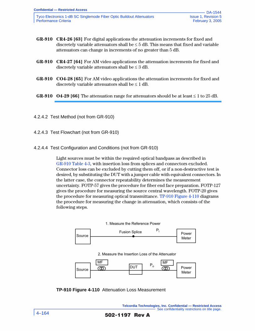
Confidential — Restricted Access
Tyco Electronics 1-dB SC Singlemode Fiber Optic Buildout Attenuators Issue 1, Revision 5Performance Criteria February 3, 2005
DA-1544
GR-910 CR4-26 [63] For digital applications the attenuation increments for fixed and discretely variable attenuators shall be ≤ 5 dB. This means that fixed and variable attenuators can change in increments of no greater than 5 dB.
GR-910 CR4-27 [64] For AM video applications the attenuation increments for fixed and discretely variable attenuators shall be ≤ 3 dB.
GR-910 CO4-28 [65] For AM video applications the attenuation increments for fixed and discretely variable attenuators shall be ≤ 1 dB.
GR-910 O4-29 [66] The attenuation range for attenuators should be at least ≤ 1 to 25 dB.
4.2.4.2 Test Method (not from GR-910)
4.2.4.3 Test Flowchart (not from GR-910)
4.2.4.4 Test Configuration and Conditions (not from GR-910)
Light sources must be within the required optical bandpass as described in GR-910 Table 4-3, with insertion loss from splices and connectors excluded. Connector loss can be excluded by cutting them off, or if a non-destructive test is desired, by substituting the DUT with a jumper cable with equivalent connectors. In the latter case, the connector repeatability determines the measurement uncertainty. FOTP-57 gives the procedure for fiber end face preparation. FOTP-127 gives the procedure for measuring the source central wavelength. FOTP-20 gives the procedure for measuring optical transmittance. TP-910 Figure 4-110 diagrams the procedure for measuring the change in attenuation, which consists of the following steps.
TP-910 Figure 4-110 Attenuation Loss Measurement
Source Power Meter
Source Power Meter
DUTMF MF
2. Measure the Insertion Loss of the Attenuator
1. Measure the Reference Power
Fusion Splice Pi
Po
�������� �� 4–164
Telcordia Technologies, Inc. Confidential — Restricted Access See confidentiality restrictions on title page.

Confidential — Restricted Access
Issue 1, Revision 5 Tyco Electronics 1-dB SC Singlemode Fiber Optic Buildout AttenuatorsFebruary 3, 2005 Performance Criteria
DA-1544
1. Fiber End Face Preparation
For attenuators with a bare fiber pigtail, the fiber end face should be clean and cleaved well or polished well if it is to be directly attached to a detector using a bare fiber adapter. Otherwise, the fiber may be connectorized or fusion spliced to a connectorized optical pigtail to facilitate light monitoring.
All connectors, connector interfaces, and connector receptacles are to be cleaned in accordance with Section 4.3 of GR-326-CORE. Make sure the
source power is off, for eye safety, and then inspect the connector end face using a microscope.
Mate attenuators with an integral connector receptacle, or connector interfaces to a connectorized fiber jumper and do not disturb the fibers launch condition.
2. Measure the Incident Optical Power, Pi
Use a stable optical power source having a central wavelength which is within the wavelength range of the attenuator under test. Connect the source to an optical power meter using a launch jumper with the same connectors as the attenuator under test. A 2-meter length of the jumper cable will be a sufficient mode filter, provided that the cable conforms to the requirements of GR-409-CORE and there are at least two 360° loops in the 2-meter length. The optical power meter should now display the incident (input) optical power, Pi. For power meters having a REFERENCE feature, press the REF key to enter Pi as the reference. The connection to the source must not be disturbed, and the coupling efficiency of the connection to the detector in Step 3 must be equivalent to the coupling efficiency obtained in Step 2.
3. Determine the Attenuation
If the attenuator under test is connectorized, mate the connector to the detector end of the launch jumper, otherwise, cut the launch jumper in half and fusion splice (with ≤ 0.02 dB loss per splice) the attenuator to both halves. The optical power meter should now display the output optical power, Po. Then the attenuation is:
A = 10 log10 (Pi / Po ) (4-6)
If the optical power meter reference feature has been used, the attenuation, A should be displayed automatically.
4. Determine the Final Attenuation
Repeat Step 3 to determine the final attenuation. Measure the attenuation in both directions of light propagation.
5. Compare Results Against Requirements
Compare the attenuation values against the requirement and objective from Section 4.2.2.
�������� �� 4–165
Telcordia Technologies, Inc. Confidential — Restricted Access See confidentiality restrictions on title page.

Confidential — Restricted Access
Tyco Electronics 1-dB SC Singlemode Fiber Optic Buildout Attenuators Issue 1, Revision 5Performance Criteria February 3, 2005
DA-1544
The transmission measurement facility in TP-910 Figure 4-111 or loss spectra (from TP-910 Figure 4-102) can also be used to determine insertion loss within a (typical) measurement uncertainty of ±0.5 dB.
In accordance with Verizon requirements, this facility is equipped to make measurements at four wavelengths, 1310 nm, 1490 nm, 1550 nm and 1625 nm, accurate to ±0.05 dB for transmittance and ±1 dB for reflectance down to –60 dB. While this measurement system is recommended, other configurations capable of meeting the relevant measurement requirements are acceptable. For attenuators in which the leads were connectorized by the supplier, the connectors and leads should be inside the test chamber to check for fiber pistoning. This may result in additional measurement uncertainty attributable to variations in connector loss. The measurement facility functions as follows: Switch 3 selects light from one of four laser sources emitting near λ1 = 1310 nm, λ2 = 1490 nm, λ3 = 1550 nm or λ4 = 1625 nm. The Device Under Test (DUT) is fusion spliced between the source switch (Switch 1) and the detector switch (Switch 2). The source switch is used to launch light into any of the devices under test. The detector switch connects any DUT to the power meter, measuring transmitted power and reflected power. The Coupler directs the optical power reflected by the DUT to port (r) on Switch 2 for detection. A reference fiber, located at port (m) of Switch 1 and 2, is used to correct for variations in source power over time. A reflectance reference (suggested value is −60 ±1 dB) is located at port (r) of Switch 1, and is used to calculate reflectance from the measured optical power. Insertion loss is calculated by subtracting the power transmitted through the reference fiber from the power transmitted through the DUT. Reflectance is calculated by subtracting the power reflected by the reflectance reference from the power reflected by the DUT. All other switch ports are dedicated to DUTs. The Switches, Power Meter and Environmental Chambers are computer controlled via GPIB interface.
TP-910 Figure 4-111 Transmission Measurement Facility
Source
�������� �� 4–166
Telcordia Technologies, Inc. Confidential — Restricted Access See confidentiality restrictions on title page.

Confidential — Restricted Access
Issue 1, Revision 5 Tyco Electronics 1-dB SC Singlemode Fiber Optic Buildout AttenuatorsFebruary 3, 2005 Performance Criteria
DA-1544
Laser sources are preferred over LEDs because source coherence affects both the DUT reflectance, and the loss of the switches. Fusion splices are recommended for their low loss and low reflectance. To obtain accurate reflectance measurements, all components in the measurement facility, including the power meter, splices and switches, should have a reflectance of ≤ −65 dB. The Coupler should have a directivity of ≥ 70 dB. Mode filters between the splices and DUT ensure single-mode transmission. A 2-meter length of the jumper cable will be a sufficient mode filter, provided that the cable conforms to the requirements of GR-409-CORE and there are at least two 360° loops in the 2 meter length. Refer to GR-326-CORE for additional details regarding measurement of loss and reflectance using the Transmission Measurement Facility.
4.2.4.5 Test Apparatus (not from GR-910)
4.2.4.6 Summary of Test Results (not from GR-910)
Conformance/Nonconformance
Not applicable.
Failure History
Not applicable.
Disposition of Nonconformance
Not applicable.
Test Data
Not applicable.
Description Supplier ModelCalibration Cycle
Calibration Due Date.
Optical Tunable Light Source Agilent 8164A 12 months –
Sensor for Tunable Multimeter Agilent 81640A 12 months –
Broadband Stabilized Light Source
Anritsu MG 922 A 12 months –
Optical Spectrum Analyzer Anritsu MS 9710 B 12 months –
Fiber cleaning supplies: alcohol, compressed air, lint-free wipes, and lint-free tipped probes
- - - -
�������� �� 4–167
Telcordia Technologies, Inc. Confidential — Restricted Access See confidentiality restrictions on title page.

Confidential — Restricted Access
Tyco Electronics 1-dB SC Singlemode Fiber Optic Buildout Attenuators Issue 1, Revision 5Performance Criteria February 3, 2005
DA-1544
4.2.5 Reflectance
The discrete reflectance, R, is the ratio of reflected power, Pr, to the incident power, Pi, in units of negative dB.
R (dB) = 10 log (Pr / Pi) (4-7)
In an attenuator, optical power may propagate in both directions. The measurement does not include reflectance from connectors unless connectors are an integral part of the attenuator.
Reflectance must be the worst-case value at a nominal wavelength for each wavelength region. Ideally, the criteria would be met for the entire bandpass.
4.2.5.1 Criteria - Reflectance (heading not from GR-910)
GR-910 R4-30 [67] The maximum reflectance for attenuators intended for use in Digital systems as bit rates up to 10 Gb/s shall be ≤ −40 dB over the entire bandpass of GR-910 CR4-17 [54] and GR-910 CO4-18 [55] and operating temperature range of −40°C to 75°C (−40°F to 167°F).
GR-910 CR4-31 [68] The maximum reflectance for attenuators intended for use in AM-VSB systems shall be ≤ −55 dB over the entire bandpass of GR-910 CR4-20 [57] and
operating temperature range of−40°C to +75°C.
GR-910 CO4-32 [69] The maximum reflectance for attenuators intended for use in AM-VSB systems should be ≤ −65 dB over the entire bandpass of GR-910 CR4-20 [57]
and operating temperature range of−40°C to +75°C.
Rationale: Low reflectance and optical return loss minimizes noise associated with reflections back to the laser source and noise caused by multiple reflection paths, both of which result in a system power penalty. The conditional requirement and objective are intended to support AM-VSB video transmission, which have been observed to incur multiple-reflection induced distortion in the presence of reflections below –60 dB. Reflectance ≤ –40 dB is most likely sufficient to support digital transmission at bit-rates up to at least 10 Gb/s. However, in future issues of Telcordia documents a single reflectance requirement and objective will be specified for all applications to limit product segregation.
�������� �� 4–168
Telcordia Technologies, Inc. Confidential — Restricted Access See confidentiality restrictions on title page.
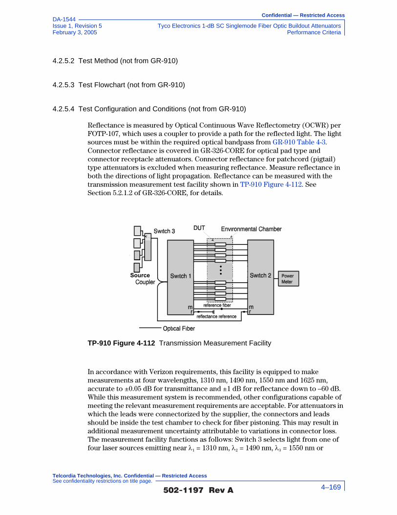
Confidential — Restricted Access
Issue 1, Revision 5 Tyco Electronics 1-dB SC Singlemode Fiber Optic Buildout AttenuatorsFebruary 3, 2005 Performance Criteria
DA-1544
4.2.5.2 Test Method (not from GR-910)
4.2.5.3 Test Flowchart (not from GR-910)
4.2.5.4 Test Configuration and Conditions (not from GR-910)
Reflectance is measured by Optical Continuous Wave Reflectometry (OCWR) per FOTP-107, which uses a coupler to provide a path for the reflected light. The light sources must be within the required optical bandpass from GR-910 Table 4-3. Connector reflectance is covered in GR-326-CORE for optical pad type and connector receptacle attenuators. Connector reflectance for patchcord (pigtail) type attenuators is excluded when measuring reflectance. Measure reflectance in both the directions of light propagation. Reflectance can be measured with the transmission measurement test facility shown in TP-910 Figure 4-112. See Section 5.2.1.2 of GR-326-CORE, for details.
In accordance with Verizon requirements, this facility is equipped to make measurements at four wavelengths, 1310 nm, 1490 nm, 1550 nm and 1625 nm, accurate to ±0.05 dB for transmittance and ±1 dB for reflectance down to –60 dB. While this measurement system is recommended, other configurations capable of meeting the relevant measurement requirements are acceptable. For attenuators in which the leads were connectorized by the supplier, the connectors and leads should be inside the test chamber to check for fiber pistoning. This may result in additional measurement uncertainty attributable to variations in connector loss. The measurement facility functions as follows: Switch 3 selects light from one of four laser sources emitting near λ1 = 1310 nm, λ2 = 1490 nm, λ3 = 1550 nm or
TP-910 Figure 4-112 Transmission Measurement Facility
Source
�������� �� 4–169
Telcordia Technologies, Inc. Confidential — Restricted Access See confidentiality restrictions on title page.

Confidential — Restricted Access
Tyco Electronics 1-dB SC Singlemode Fiber Optic Buildout Attenuators Issue 1, Revision 5Performance Criteria February 3, 2005
DA-1544
λ4 = 1625 nm. The Device Under Test (DUT) is fusion spliced between the source switch (Switch 1) and the detector switch (Switch 2). The source switch is used to launch light into any of the devices under test. The detector switch connects any DUT to the power meter, measuring transmitted power and reflected power. The Coupler directs the optical power reflected by the DUT to port (r) on Switch 2 for detection. A reference fiber, located at port (m) of Switch 1 and 2, is used to correct for variations in source power over time. A reflectance reference (suggested value is −60 ±1 dB) is located at port (r) of Switch 1, and is used to calculate reflectance from the measured optical power. Insertion loss is calculated by subtracting the power transmitted through the reference fiber from the power transmitted through the DUT. Reflectance is calculated by subtracting the power reflected by the reflectance reference from the power reflected by the DUT. All other switch ports are dedicated to DUTs. The Switches, Power Meter and Environmental Chambers are computer controlled via GPIB interface.
Laser sources are preferred over LEDs because source coherence affects both the DUT reflectance, and the loss of the switches. Fusion splices are recommended for their low loss and low reflectance. To obtain accurate reflectance measurements, all components in the measurement facility, including the power meter, splices and switches, should have a reflectance of ≤ −65 dB. The Coupler should have a directivity of ≥ 70 dB. Mode filters between the splices and DUT ensure single-mode transmission. A 2-meter length of the jumper cable will be a sufficient mode filter, provided that the cable conforms to the requirements of GR-409-CORE and there are at least two 360° loops in the 2 meter length. Refer to GR-326-CORE for additional details regarding measurement of loss and reflectance using the Transmission Measurement Facility.
4.2.5.5 Test Apparatus (not from GR-910)
Description Supplier ModelCalibration Cycle
Calibration Due Date.
Optical Tunable Light Source Agilent 8164A 12 months –
Sensor for Tunable Multimeter Agilent 81640A 12 months –
Broadband Stabilized Light Source
Anritsu MG 922 A 12 months –
Optical Spectrum Analyzer Anritsu MS 9710 B 12 months –
Fiber cleaning supplies: alcohol, compressed air, lint-free wipes, and lint-free tipped probes
- - - -
�������� �� 4–170
Telcordia Technologies, Inc. Confidential — Restricted Access See confidentiality restrictions on title page.
Confidential — Restricted Access
Issue 1, Revision 5 Tyco Electronics 1-dB SC Singlemode Fiber Optic Buildout AttenuatorsFebruary 3, 2005 Performance Criteria
DA-1544
4.2.5.6 Summary of Test Results (not from GR-910)
Conformance/Nonconformance
The baseline reflectance measurements presented in TP-910 Figure 4-113 shows conformance to GR-910 R4-30 [67] and GR-910 CR4-31 [68], but shows nonconformance to GR-910 CO4-32 [69]. this is a conditional objective and it is up to the end user the significance of this nonconforming issue. Conformance is based on demonstration that the maximum reflectance for attenuators is not exceeded for both digital systems as well as analog systems before, during and after environmental and mechanical stress as applied to in Section 4.1. The status of each requirement is described in each pertinent section of Section 4.1.
Sample Size
Eleven samples, in accordance with 20% LTPD specified in GR-910-CORE, Issue 2, were used in the test program. In addition, eleven samples were added to serve as hot spares for replacing sample(s) with nonconformance identified in the test program.
Failure History
Not applicable.
Disposition of Nonconformance
Not applicable.
Test Data
The following chart represents the entire set of samples tested. This includes a total of eleven (11) samples of buildout attenuators (BOA). TP-910 Figure 4-113 presents the reflectance measurements (including connection losses of about 0.5 dB) taken as a baseline for all of the eleven test samples at 1310 nm, 1490 nm, 1550 nm and 1625 nm, respectively. Refer to the results presented in Section 4.1 for the during and after test measurements of which these values are compared to.
�������� �� 4–171
Telcordia Technologies, Inc. Confidential — Restricted Access See confidentiality restrictions on title page.

Confidential — Restricted Access
Tyco Electronics 1-dB SC Singlemode Fiber Optic Buildout Attenuators Issue 1, Revision 5Performance Criteria February 3, 2005
DA-1544
4.2.6 Polarization-Dependent Loss (PDL)
PDL is the variation in insertion loss as the state of polarization (SOP) of the incident signal is varied over all orientations.
4.2.6.1 Criteria - Polarization-Dependent Loss (heading not from GR-910)
GR-910 R4-33 [70] All optical requirements shall be met for all incident SOPs.
GR-910 CR4-34 [71] For digital applications the maximum change in attenuation shall be ≤ 0.5 dB or ≤ 0.15A, whichever is less.
GR-910 CR4-35 [72] For AM video applications the maximum change in attenuation shall be ≤ 0.5 dB or ≤ 0.10A, whichever is less.
Rationale: The SOP of light propagating through fiber optic transmission systems, using conventional Class IVa single-mode fiber, is indeterminate. Therefore, attenuators used in these systems must be insensitive to the SOP.
TP-910 Figure 4-113 Baseline Reflectance Measurements at 1310 nm, 1490 nm, 1550 nm and 1625 nm
TYCO Electronics, 1-dB Attenuators, Reflectance-70.0
-65.0
-60.0
-55.0
-50.0
-45.0
-40.0
-35.0
-30.0i.l.01 i.l.02 i.l.03 i.l.04 i.l.05 i.l.06 i.l.07 i.l.08 i.l.09 i.l.10 i.l.11
Sample
Refle
ctan
ce (d
B)
1310 nm 1490 nm1550 nm 1625 nmReq (D) Req (A)CR (A)
`
�������� �� 4–172
Telcordia Technologies, Inc. Confidential — Restricted Access See confidentiality restrictions on title page.

Confidential — Restricted Access
Issue 1, Revision 5 Tyco Electronics 1-dB SC Singlemode Fiber Optic Buildout AttenuatorsFebruary 3, 2005 Performance Criteria
DA-1544
4.2.6.2 Test Method (not from GR-910)
1. Clean all optical connectors prior to use following cleaning procedure A or B described in GR-326-CORE, Section 4.3.
The following cleaning procedure (Procedure A) shall be followed, unless the manufacturer of the DUT provides an alternative procedure (Procedure B).
a. If both plugs have been removed from the adapter, blow compressed gas through the adapter. If both plugs are not to be removed, blow compressed gas into the open end of the adapter.
b. Wipe completely around the ferrule of the plug twice with a lint-free wiping material that has been moistened with alcohol. Then wipe across the end of the ferrule.
c. Repeat Step (b.) with a dry wipe.
d. Blow compressed gas across the end of the ferrule. This is the final step before inserting the plug. Do not wipe the ferrule or allow it to touch anything after completion of this step and before the ferrule is inserted into the sleeve.
e. Insert the plug in the adapter.
f. If both plugs have been removed, repeat Steps (b.) through (e.) with the second plug.
2. Determine the output power spectrum launched by the light source being used with equipment shown in TP-910 Figure 4-115 to perform baseline reference measurements: received power versus wavelength. Sweep the light source or spectrum analyzer through the full range of operational wavelengths that comprise the DUT’s anticipated bandwidth.
3. Save baseline measurements with their respective wavelength λi, as the reference power, Reference Poweri, for each output fiber on hard disk.
4. Insert the device under test and a polarization controller into the test setup shown in TP-910 Figure 4-116.
5. Record polarization dependent power for each DUT output fiber, DUT
Polarization Poweri, versus wavelength, λk, on hard disk. Sweep the light source through the full range of operational wavelengths that comprise the DUT’s anticipated bandwidth. During this measurement the polarization controller will be required to rotate the light through all states of polarization. The variations between the maximum and minimum DUT polarization poweri will define the variation in PDL of each DUT output fiber.
6. Compute the polarization dependent loss versus wavelength for each output fiber of the DUT by subtracting the reference power level for each wavelength from the power level with the DUT in place for the same wavelength.
Max PDLi = Reference Poweri – Max DUT Polarization Poweri
�������� �� 4–173
Telcordia Technologies, Inc. Confidential — Restricted Access See confidentiality restrictions on title page.

Confidential — Restricted Access
Tyco Electronics 1-dB SC Singlemode Fiber Optic Buildout Attenuators Issue 1, Revision 5Performance Criteria February 3, 2005
DA-1544
Min PDLi = Reference Poweri – Min DUT Polarization Poweri
7. Compute the range of polarization dependent loss, ∆LI, versus wavelength for each output fiber of the DUT by calculating the difference between the maximum and minimum DUT Polarization Poweri for each.
∆LI = Max DUT Polarization Poweri - Min DUT Polarization Poweri
8. Does Max and Min PDLi meet all optical requirements of GR-910 for all SOP as per GR-910?
9. No – investigate the nature of the failure using the Telcordia Nonconforming Product Process.
10. Yes – does ∆LI meet the requirements of GR-910?
11. No – investigate the nature of the failure using the Telcordia Nonconforming Product Process.
12. Go on to the next product test.
�������� �� 4–174
Telcordia Technologies, Inc. Confidential — Restricted Access See confidentiality restrictions on title page.

Confidential — Restricted Access
Issue 1, Revision 5 Tyco Electronics 1-dB SC Singlemode Fiber Optic Buildout AttenuatorsFebruary 3, 2005 Performance Criteria
DA-1544
4.2.6.3 Test Flowchart (not from GR-910)
Setup Equipment as is shown in TP-1209Figure 4-48.
Insert device under test (DUT) andpolarization controller into
test setup, as per TP-1209 Figure 4-49.
Compute polarization dependent loss vs for each DUToutput fiber by subtracting the reference power leveli for eachwavelength from the power level with the DUT in place for the
same wavelength.
Max PDLi = Reference Poweri - Max DUT Polarization Poweri
Min PDLi = Reference Poweri - Min DUT Polarization Poweri
Perform baseline measurements: Reference Pwri versus i, save.
Perform DUT measurements:DUT Polarization Pwri versus i, save.
Clean all optical connectors, see GR-326-CORE, Section 4.3, Method A or B.
Continue
Compute range of polarization dependent loss, LI, versus for eachDUT output fiber by calculating difference between the maximum and
minimum DUT Polarization Poweri for each. LI = Max DUT Polarization Poweri - Min DUT Polarization Poweri
Wipe each plug twice with lint-freecloth moistened with alcohol. Wipe
across end of ferrule.
Blow compressed air through theconnector adapter.
Wipe each plug twice with lint-freecloth. Wipe across end of ferrule.
Blow compressed air through theconnector adapter.
Insert mating connector plugs inadapter.
�������� �� 4–175
Telcordia Technologies, Inc. Confidential — Restricted Access See confidentiality restrictions on title page.

Confidential — Restricted Access
Tyco Electronics 1-dB SC Singlemode Fiber Optic Buildout Attenuators Issue 1, Revision 5Performance Criteria February 3, 2005
DA-1544
continue
Investigate the nature of thefailure using the Telcordia Non-Conforming Product Process.
Does Max and MinPDLi meet all optical criteiria
of GR-1209for all SOP as per
GR-1209R4-52 [85]?
Yes
No
Investigate the nature of thefailure using the Telcordia Non-Conforming Product Process.
Does LImeet requirements of GR-
1209 R4-53 [86]?No
Yes
Test DUT as a filterIs DUT and Isolatoror a circulator?
No
Yes
Continue
�������� �� 4–176
Telcordia Technologies, Inc. Confidential — Restricted Access See confidentiality restrictions on title page.

Confidential — Restricted Access
Issue 1, Revision 5 Tyco Electronics 1-dB SC Singlemode Fiber Optic Buildout AttenuatorsFebruary 3, 2005 Performance Criteria
DA-1544
continue
Investigate the nature of the failure usingthe Telcordia Non-Conforming Product
Process.
Does isolator or circulator Max and Min PDLi meet all optical
requirements of GR-1209 for all SOP asper GR-1209 R4-54 [87]?
Yes
No
Investigate the nature of thefailure using the Telcordia Non-Conforming Product Process.
Does LI meet requirementsof GR-1209 R4-55 [88] for isolators
and GR-1209 R4-56 [89] forcirculators?
No
Yes
Is DUT a filter? No
Yes
Continue
Go on to nextproduct test
�������� �� 4–177
Telcordia Technologies, Inc. Confidential — Restricted Access See confidentiality restrictions on title page.

Confidential — Restricted Access
Tyco Electronics 1-dB SC Singlemode Fiber Optic Buildout Attenuators Issue 1, Revision 5Performance Criteria February 3, 2005
DA-1544
4.2.6.4 Test Configuration and Conditions (not from GR-910)
The intent of this test is to determine compliance with the optical criteria given in Section 4.2.2 through Section 4.2.6, given incident light which is linearly polarized at any angle. Methods to more accurately determine PDL and the polarization sensitivity of passive components require further development, and such development is ongoing. Some test instruments now measure PDL.
TP-910 Figure 4-117 shows a configuration for measuring PDL using a fiber coupled Polarization Controller (PC). The PC is a device that adjusts to select any SOP, such as an all-fiber PC, or a combination of a linear polarizer (P), quarter-wave plate (Q), and a half-wave plate (H), which are compatible with the wavelength of the source. The important characteristics of the measurement apparatus are:
• PDL must be demonstrated for at least at one nominal wavelength within each of the 1310 nm and 1550 nm regions.
• The Optical Source launches temporally stable light, with ≤ 10 nm spectral width, and an extinction ratio of ≥ 20 dB, into single-mode fiber.
• Bends in conventional Class IVa or IVb single-mode fiber will modify the state of polarization. For this reason, the device launch pigtail must be deployed in a straight configuration, and must not be moved during the polarization measurement.
TP-910 Figure 4-114 Test Flowchart - PDL Test (not from GR-910)
continue
Investigate the nature of the failure usingthe Telcordia Non-Conforming Product
Process.No
Yes
Does filter LI meet therequirements
of GR-1209 R4-58 [91]?
Go on to nextproduct test
�������� �� 4–178
Telcordia Technologies, Inc. Confidential — Restricted Access See confidentiality restrictions on title page.

Confidential — Restricted Access
Issue 1, Revision 5 Tyco Electronics 1-dB SC Singlemode Fiber Optic Buildout AttenuatorsFebruary 3, 2005 Performance Criteria
DA-1544
• The DUT should be spliced into the optical path to avoid varying the SOP, otherwise connect the attenuator between the PC and the detector power meter. Attenuators with connectors incur a greater PDL.
• The test procedures in Section 5.2.1 through Section 5.2.4 are to be followed, to measure the particular optical characteristic of interest.
• Adjust the polarization controller to measure the worst-case value for the characteristic of interest. The plane of polarization should be rotated through an angle of ≥ 180°.
If using a PQH Controller:
• Rotate P until the maximum power is obtained.
• Alternatively, rotate Q and H to obtain the worst-case value for the characteristic of interest.
• To determine ∆L, alternatively, rotate Q and H to obtain the highest power level, and subtract from the lowest power level (from the previous step)
TP-910 Figure 4-115 Reference Configuration for PDL Tests (not from GR-910)
TP-910 Figure 4-116 Through-DUT Configuration for PDL Tests (not from GR-910)
TP-910 Figure 4-117 Configuration for Measuring Polarization Dependent Loss
Opticalpowermeter
Tunablelaser
Opticalpowermeter
Tunablelaser DUTPolarization
controller
OpticalSource
DUT PowerM eter
PolarizationController
�������� �� 4–179
Telcordia Technologies, Inc. Confidential — Restricted Access See confidentiality restrictions on title page.

Confidential — Restricted Access
Tyco Electronics 1-dB SC Singlemode Fiber Optic Buildout Attenuators Issue 1, Revision 5Performance Criteria February 3, 2005
DA-1544
4.2.6.5 Test Apparatus (not from GR-910)
4.2.6.6 Summary of Test Results (not from GR-910)
Conformance/Nonconformance
All of the eleven samples conformed to the criteria in Section 4.2.6.1 of this document. Conformance is based on demonstration that all optical requirements are met for all incident states of polarization and that the maximum change in attenuation is within the required criteria.
Sample Size
Eleven samples, in accordance with 20% LTPD specified in GR-910-CORE, Issue 2, were used in the test program. In addition, eleven samples were added to serve as hot spares for replacing sample(s) with nonconformance identified in the test program.
Failure History
Not applicable.
Disposition of Nonconformance
Not applicable.
Test Data
The following chart represents the entire set of samples tested. This includes a total of eleven (11) samples of buildout attenuators (BOA). TP-910 Figure 4-118 presents Polarization-Dependent Loss (PDL) measurements for all of the eleven test samples at 1310 nm, 1490 nm, 1550 nm and 1625 nm, respectively.
Description Supplier ModelCalibration Cycle
Calibration Due Date.
Optical Tunable Light Source Agilent 8164A 12 months –
Sensor for Tunable Multimeter Agilent 81640A 12 months –
Polarization Controller HP 11896A 12 months –
Fiber cleaning supplies: alcohol, compressed air, lint-free wipes, and lint-free tipped probes
- - - -
�������� �� 4–180
Telcordia Technologies, Inc. Confidential — Restricted Access See confidentiality restrictions on title page.

Confidential — Restricted Access
Issue 1, Revision 5 Tyco Electronics 1-dB SC Singlemode Fiber Optic Buildout AttenuatorsFebruary 3, 2005 Performance Criteria
DA-1544
4.2.7 Polarization-Mode Dispersion (PMD)
PMD is the dispersion, or difference between arrival times, of pulses which travel through optical fiber as ordinary and extraordinary rays. In optical fiber cable, PMD is statistical, varying with time and changes in wavelength, temperature, vibration, etc. Although, PMD in optical components is more stable and the ratio of standard deviation to the mean is much smaller, optical components contribute to the overall PMD of an optical transmission system. All optical components including attenuators must be compatible with optical fiber transmission systems and not contribute significantly to the total PMD in the optical path.
4.2.7.1 Criteria - Polarization Mode Dispersion (heading not from GR-910)
GR-910 R4-36 [79] The maximum value of dispersion (in ps) shall not exceed 0.2 ps for all operating wavelengths.
TP-910 Figure 4-118 Polarization-Dependent Loss (PDL) at 1310 nm, 1490 nm, 1550 nm and 1625 nm
TYCO Electronics, 1-dB Attenuators, PDL
0.00
0.02
0.04
0.06
0.08
0.10
0.12
0.14
0.16
i.l.01 i.l.02 i.l.03 i.l.04 i.l.05 i.l.06 i.l.07 i.l.08 i.l.09 i.l.10 i.l.11
Sample #
PDL
(dB)
1310 nm 1490 nm1550 nm 1625 nmReq (D) Req (A)
�������� �� 4–181
Telcordia Technologies, Inc. Confidential — Restricted Access See confidentiality restrictions on title page.

Confidential — Restricted Access
Tyco Electronics 1-dB SC Singlemode Fiber Optic Buildout Attenuators Issue 1, Revision 5Performance Criteria February 3, 2005
DA-1544
4.2.7.2 Test Method (not from GR-910)
1. Clean all optical connectors prior to use following cleaning procedure A or B described in GR-326-CORE, Section 4.3.
The following cleaning procedure (Procedure A) shall be followed, unless the manufacturer of the DUT provides an alternative procedure (Procedure B).
a. If both plugs have been removed from the adapter, blow compressed gas through the adapter. If both plugs are not to be removed, blow compressed gas into the open end of the adapter.
b. Wipe completely around the ferrule of the plug twice with a lint-free wiping material that has been moistened with alcohol. Then wipe across the end of the ferrule.
c. Repeat Step (b.) with a dry wipe.
d. Blow compressed gas across the end of the ferrule. This is the final step before inserting the plug. Do not wipe the ferrule or allow it to touch anything after completion of this step and before the ferrule is inserted into the sleeve.
e. Insert the plug in the adapter.
f. If both plugs have been removed, repeat Steps (b.) through (e.) with the second plug.
2. Determine the output power spectrum launched by the light source being used with equipment shown in TP-910 Figure 4-120 to perform baseline reference measurements: received power versus wavelength. Sweep the light source or spectrum analyzer through the full range of operational wavelengths that comprise the DUT’s anticipated bandwidth.
3. Measure the PMD delay time for each DUT output fiber using the PMD test setup shown in TP-910 Figure 4-121.
4. Does the PMD delay time for each DUT output fiber meet GR-910?
5. No – investigate the nature of the failure using the Telcordia Nonconforming Product Process.
6. Go on to the next product test.
�������� �� 4–182
Telcordia Technologies, Inc. Confidential — Restricted Access See confidentiality restrictions on title page.

Confidential — Restricted Access
Issue 1, Revision 5 Tyco Electronics 1-dB SC Singlemode Fiber Optic Buildout AttenuatorsFebruary 3, 2005 Performance Criteria
DA-1544
4.2.7.3 Test Flowchart (not from GR-910)
Setup Equipment and DUT as is shown inTP-1209 Figure 4-60. Note, equipment
includes a PMD transmitter and receiver.
Perform PMD delay time measurements:DUT Polarization Pwri versus i, save.
Clean all optical connectors, see GR-326-CORE, Section 4.3, Method A or B.
Investigate the nature of thefailure using the TelcordiaNon-Conforming Product
Process.
Does PMD delaytimefor DUT output fiber
meet GR-1209R4-60 [93]?
No
Yes
Is the DUT anisolator or circulator? Skip to next product test,No
Yes
Investigate the nature ofthe failure using the
Telcordia Non-Conforming Product
Process.
Does PMD delaytime for isolator/circulator
meet GR-1209R4-61 [94]
No
Yes
Wipe each plug twice with lint-freecloth moistened with alcohol. Wipe
across end of ferrule.
Blow compressed air through theconnector adapter.
Wipe each plug twice with lint-freecloth. Wipe across end of ferrule.
Blow compressed air through theconnector adapter.
Insert mating connector plugs inadapter.
continue
�������� �� 4–183
Telcordia Technologies, Inc. Confidential — Restricted Access See confidentiality restrictions on title page.

Confidential — Restricted Access
Tyco Electronics 1-dB SC Singlemode Fiber Optic Buildout Attenuators Issue 1, Revision 5Performance Criteria February 3, 2005
DA-1544
4.2.7.4 Test Configuration and Conditions (not from GR-910)
The measurement of PMD can be accomplished by the fixed analyzer method in FOTP-113, the Jones matrix analysis in FOTP-122, or the interferometric method in FOTP-124. There are commercially available measurement instruments capable of measuring PDL and PMD.
TP-910 Figure 4-119 Test Flowchart - PMD (not from GR-910)
continue
Investigate the nature ofthe failure using the
Telcordia Non-Conforming Product
Process.
Does variation in fc forpolarization effect meetGR-1209 R4-59 [92]?
No
Yes
Compute the central frequency,fc ,for both curves.
Go on to next producttest.
TP-910 Figure 4-120 Reference Configuration for PMD Tests (not from GR-910)
PMDLight
Source
PMDReceiver
�������� �� 4–184
Telcordia Technologies, Inc. Confidential — Restricted Access See confidentiality restrictions on title page.

Confidential — Restricted Access
Issue 1, Revision 5 Tyco Electronics 1-dB SC Singlemode Fiber Optic Buildout AttenuatorsFebruary 3, 2005 Performance Criteria
DA-1544
4.2.7.5 Test Apparatus (not from GR-910)
4.2.7.6 Summary of Test Results (not from GR-910)
Conformance/Nonconformance
All of the eleven samples conformed to the criteria in Section 4.2.7.1 of this document. Conformance is based on demonstration that the maximum value of dispersion is not exceeded for all operating wavelengths.
Sample Size
Eleven samples, in accordance with 20% LTPD specified in GR-910-CORE, Issue 2, were used in the test program. In addition, eleven samples were added to serve as hot spares for replacing sample(s) with nonconformance identified in the test program.
Failure History
Not applicable.
Disposition of Nonconformance
Not applicable.
TP-910 Figure 4-121 Configuration for PMD Tests (not from GR-910)
PMDLight
SOurceDUT PMD
Receiver
Description Supplier ModelCalibration Cycle
Calibration Due Date.
PMD Light Source EXFO FLS210A-03B-70 12 months –
PMD Receiver EXFO 5500 12 months –
Fiber cleaning supplies: alcohol, compressed air, lint-free wipes, and lint-free tipped probes
- - - -
�������� �� 4–185
Telcordia Technologies, Inc. Confidential — Restricted Access See confidentiality restrictions on title page.

Confidential — Restricted Access
Tyco Electronics 1-dB SC Singlemode Fiber Optic Buildout Attenuators Issue 1, Revision 5Performance Criteria February 3, 2005
DA-1544
Test Data
The following chart represents the entire set of samples tested. This includes a total of eleven (11) samples of buildout attenuators (BOA). TP-910 Figure 4-122 presents Polarization-Mode Dispersion (PMD) measurements for all of the eleven test samples.
4.2.8 Damage Criteria
Damage criteria apply after each of the Environmental and Mechanical Tests, and after all testing. The attenuators and associated parts (i.e., connectors, pigtails) shall be inspected for damage that might impair the performance of the attenuator. This inspection shall include inspections for
• Distortion
• Package Cracks
• Hardening or Softening of Materials
• Fiber Breakage
• Cable Pullout
• Cable Jacket Damage
• Cable Seal Damage
TP-910 Figure 4-122 Polarization-Mode Dispersion (PMD) measurements
Tyco Electronics, 1-dB Attenuators, PMD
0.00
0.05
0.10
0.15
0.20
0.25
i.l.01 i.l.02 i.l.03 i.l.04 i.l.05 i.l.06 i.l.07 i.l.08 i.l.09 i.l.10 i.l.11Sample#
PMD
(ps)
PMD (ps)Req.
�������� �� 4–186
Telcordia Technologies, Inc. Confidential — Restricted Access See confidentiality restrictions on title page.

Confidential — Restricted Access
Issue 1, Revision 5 Tyco Electronics 1-dB SC Singlemode Fiber Optic Buildout AttenuatorsFebruary 3, 2005 Performance Criteria
DA-1544
• Damage to the Attenuation Element
• Damage to the Variable Attenuation Adjustment Mechanism.
4.2.8.1 Criteria - Damage (heading not from GR-910)
GR-910 R4-37 [73] At the completion of all tests there shall be no damage that would impair the performance of the attenuator.
4.2.8.2 Test Method (not from GR-910)
1. Review for damage is provided as a step within the test procedures documented in this section for each individual test.
2. Any damage observed and reported as a part of the other test procedures in this section shall be summarized for overall damage criteria conformance per the above requirement.
4.2.8.3 Test Flowchart (not from GR-910)
Not applicable
4.2.8.4 Test Configuration and Conditions (not from GR-910)
Not applicable
4.2.8.5 Test Apparatus (not from GR-910)
Not applicable
4.2.8.6 Summary of Test Results (not from GR-910)
Conformance/Nonconformance
All of the eleven samples conformed to the criteria in Section 4.2.8.1 of this document. Conformance is based on demonstration that upon completion of all tests there is no damage sustained that would impair the performance of the attenuator.
Sample Size
Eleven samples, in accordance with 20% LTPD specified in GR-910-CORE, Issue 2, were used in the test program. In addition, eleven samples were added to serve as
�������� �� 4–187
Telcordia Technologies, Inc. Confidential — Restricted Access See confidentiality restrictions on title page.

Confidential — Restricted Access
Tyco Electronics 1-dB SC Singlemode Fiber Optic Buildout Attenuators Issue 1, Revision 5Performance Criteria February 3, 2005
DA-1544
hot spares for replacing sample(s) with nonconformance identified in the test program.
Failure History
Not applicable.
Disposition of Nonconformance
Not applicable.
Test Data
Not applicable.
�������� �� 4–188
Telcordia Technologies, Inc. Confidential — Restricted Access See confidentiality restrictions on title page.

Confidential — Restricted Access
Issue 1, Revision 5 Tyco Electronics 1-dB SC Singlemode Fiber Optic Buildout AttenuatorsFebruary 3, 2005 Performance Verification/Test Procedures
DA-1544
5.0 Performance Verification/Test Procedures
This section describes the test procedures for the performance analysis of single-mode fiber optic attenuators. These configurations and procedures are recommended. However, other configurations and procedures capable of meeting the relevant measurement requirements are not excluded.
The performance verification and test procedures presented in this section are presented in parallel with the requirements given in Section 4, and they will be used as a basis for analyzing attenuators. Performance tests are designed not only to verify performance of attenuators, but also to determine the performance of attenuators under severe environmental and mechanical conditions which may degrade their performance.
The standard test procedures and conditions defined in EIA/TIA-455-A are to be used for testing. The following conditions also apply to these test procedures:
• All tests are performed at a room temperature of 23° ± 5°C (73° ± 9°F) and a relative humidity of 30% to 70% unless otherwise specified.
• The test instruments are allowed to stabilize for the minimum time specified by the equipment manufacturer prior to any measurement or 1 hour, whichever is greater.
• All test equipment is properly calibrated. Optical power meters have a relative accuracy ≤ 0.05 dB for all power levels from 0 dBm to ≤ - 80 dBm, for all wavelengths from 1260 nm to 1580 nm.
• Work procedures, such as the mating of connectors or the adjustments of attenuator settings, that have a potential for altering the measurements are performed strictly in accordance with the written instructions supplied with the product.
• The manufacturer selects1 samples of the product to be used in the analysis at random, from stock that represents the manufacturer's normal production. The sample of the product for analysis shall be shipped by the manufacturer to the testing agency with the complete packing and marking that product supplied to a customer would normally have.
• The performance of an optical attenuator may depend on the cleanliness of the attenuation element, connector receptacle and integral connectors, or connector interfaces. It is the responsibility of the supplier to provide cleaning instructions for attenuation elements that are accessible to the end user. Attenuators with accessible attenuation elements shall be cleaned according to the suppliers instructions. All optical connector receptacles, connectors, and connector interfaces shall be cleaned in accordance with Section 4.3 of GR-326-CORE.
1. Telcordia reserves the option to select product for analysis.
�������� �� 5–1
Telcordia Technologies, Inc. Confidential — Restricted Access See confidentiality restrictions on title page.

Confidential — Restricted Access
Tyco Electronics 1-dB SC Singlemode Fiber Optic Buildout Attenuators Issue 1, Revision 5Performance Verification/Test Procedures February 3, 2005
DA-1544
• A minimum of 11 attenuator samples per test allowing no failures is suggested for testing per FOTP-3A. This corresponds to a Lot Tolerance Percentage Defective (LTPD) of 20%. LTPD is described in Appendix B of Military Specification MIL-M-38510J. Smaller sample sizes are not sufficient to establish a statistically meaningful result.
• All samples undergo sequential testing in the order presented in this document.
5.1 Environmental and Mechanical Testing
These tests are intended to demonstrate the operation of attenuators under environmental stress, but not reliability. For a complete set of reliability tests, refer to GR-1221-CORE.
For each test, compliance against the change in attenuation criteria is determined by measuring the attenuation as described in Section 5.2.2, or measure the optical transmittance and calculate the attenuation per FOTP-20, during or after each test. The compliance against the reflectance criteria is determined by measuring reflectance per FOTP-107, during or after each test. Visual and mechanical inspection should follow FOTP-13.
The operating and non-operating environmental criteria require monitoring during
testing. This can be accomplished using a Transmission Measurement Facility shown in GR-910 Figure 5-1, or another comparable system.
This facility makes measurements in both the 1310 nm and 1550 nm wavelength regions, accurate to ± 0.05 dB for transmittance and ± 1 dB for reflectance down to - 60 dB. While this measurement system is recommended, other configurations capable of meeting the relevant measurement requirements are acceptable. For attenuators in which the leads were connectorized by the supplier, the connectors
GR-910 Figure 5-1 Transmission Measurement Facility
�������� �� 5–2
Telcordia Technologies, Inc. Confidential — Restricted Access See confidentiality restrictions on title page.

Confidential — Restricted Access
Issue 1, Revision 5 Tyco Electronics 1-dB SC Singlemode Fiber Optic Buildout AttenuatorsFebruary 3, 2005 Performance Verification/Test Procedures
DA-1544
and leads should be inside the test chamber to check for fiber pistoning. This may result in additional measurement uncertainty attributable to variations in connector loss. The measurement facility functions as follows: Switch 3 selects light from one of two laser sources emitting near λ1 = 1310 nm or λ2 = 1550 nm. The Device Under Test (DUT) is fusion spliced between the source switch (Switch 1) and the detector switch (Switch 2). The source switch is used to launch light into any of the devices under test. The detector switch connects any DUT to the power meter, measuring transmitted power and reflected power. The Coupler directs the optical power reflected by the DUT to port (r) on Switch 2 for detection. A reference fiber, located at port (m) of Switch 1 and 2, is used to correct for variations in source power over time. A reflectance reference (suggested value is − 60 ± 1 dB) is located at port (r) of Switch 1, and is used to calculate reflectance from the measured optical power. Insertion loss is calculated by subtracting the power transmitted through the reference fiber from the power transmitted through the DUT. Reflectance is calculated by subtracting the power reflected by the reflectance reference from the power reflected by the DUT. All other switch ports are dedicated to DUTs. The Switches, Power Meter and Environmental Chambers are computer controlled via GPIB interface.
Laser sources are preferred over LEDs because source coherence affects both the DUT reflectance, and the loss of the switches. Fusion splices are recommended for their low loss and low reflectance. To obtain accurate reflectance measurements, all components in the measurement facility, including the power meter, splices and switches, should have a reflectance ≤ − 65 dB. The Coupler should have a directivity of ≥ 70 dB. Mode filters between the splices and DUT ensure single-mode transmission. A 2-meter length of the jumper cable will be a sufficient mode filter, provided that the cable conforms to the requirements of GR-409-CORE and there are at least two 360° loops in the 2 meter length. Refer to GR-326-CORE for additional details regarding measurement of loss and reflectance using the Transmission Measurement Facility.
5.1.1 Controlled Operating Environment
The product shall be tested according to the performance requirements in Section 4 while being exposed to the temperatures and humidity specified in Section 5.1.2, Operating Temperature and Relative Humidity, in GR-63-CORE. The controlled operating environment temperature profile is shown in GR-910 Figure 5-2. Measurements should be taken at each temperature plateau. Upon reaching a temperature measurement point the test samples should be allowed to stabilize for a one-half hour minimum before measuring attenuation and reflectance. The final measurement shall be made after the test samples have stabilized at 23°C for a minimum or 2 hours. The requirements in Section 4.1.1 apply before during and after the test.
�������� �� 5–3
Telcordia Technologies, Inc. Confidential — Restricted Access See confidentiality restrictions on title page.

Confidential — Restricted Access
Tyco Electronics 1-dB SC Singlemode Fiber Optic Buildout Attenuators Issue 1, Revision 5Performance Verification/Test Procedures February 3, 2005
DA-1544
5.1.2 Uncontrolled Operating Environment
Attenuators intended for use in an uncontrolled environment (outside plant) shall be subjected to the temperature cycling profile in GR-910 Figure 5-3 per FOTP 3A, for 21 cycles, 168 hours. The relative humidity is uncontrolled. Measurements should be taken at each temperature plateau once per day. Upon reaching a temperature measurement point the test samples should be allowed to stabilize for a one-half hour minimum before measuring attenuation and reflectance. The final measurement shall be made after the test samples have stabilized at 23°C for a minimum or 2 hours. The requirements in Section 4.1.2 apply before during and after the test.
GR-910 Figure 5-2 Controlled Operating Environment Temperature Profile
-10
0
10
20
30
40
50
60
0 48 96 144 192
Time - Hours
Tem
pera
ture
°C
�������� �� 5–4
Telcordia Technologies, Inc. Confidential — Restricted Access See confidentiality restrictions on title page.

Confidential — Restricted Access
Issue 1, Revision 5 Tyco Electronics 1-dB SC Singlemode Fiber Optic Buildout AttenuatorsFebruary 3, 2005 Performance Verification/Test Procedures
DA-1544
5.1.3 Non-Operating Environment
The product shall be tested according to the performance requirements in Section 4 while being exposed to the temperatures and humidity specified in Sections 5.1.1.1, 5.1.1.2, and 5.1.1.1.3 per GR-63-CORE for low-temperature exposure and thermal shock, high-temperature exposure and thermal shock, and high relative humidity exposure respectively. The requirements in Section 4.1.3 apply before and after each test.
5.1.4 Humidity/Condensation Cycling Test
The product shall be tested according to the performance requirements in Section 4 while being exposed to the modified temperatures and humidity profile shown in GR-910 Figure 5-4 per FOTP 3A, for 14 cycles, 168 hours. The relative humidity shall be ≥ 90% at interval four, 65°C, and at interval eight, 23°C. Measurements should be taken at each temperature plateau. Upon reaching a temperature measurement point the test samples should be allowed to stabilize for a one-half hour minimum before measuring attenuation and reflectance. The final measurement shall be made after the test samples have stabilized at 23°C for a minimum or 2 hours. The requirements in Section 4.1.4 apply before during and after the test.
GR-910 Figure 5-3 Uncontrolled Environment Temperature Profile
-50-40-30-20-10
01020304050607080
0 1 2 3 4 5 6 7 8 9
Time - Hours
Tem
pera
ture
°C
�������� �� 5–5
Telcordia Technologies, Inc. Confidential — Restricted Access See confidentiality restrictions on title page.

Confidential — Restricted Access
Tyco Electronics 1-dB SC Singlemode Fiber Optic Buildout Attenuators Issue 1, Revision 5Performance Verification/Test Procedures February 3, 2005
DA-1544
5.1.5 Water Immersion
This test is to be performed according to GR-1221-CORE, Section 6.2.10, Water
Immersion Test, which is based on FOTP-12. Attenuator test samples are to be subjected to immersion in water (pH 5.5 ± 0.5) at 43° ± 2°C (109 ± 4°F) for 7 days. The pH level can be set by mixing a standard buffer solution containing sodium hydroxide and acetic acid. The pH level should be checked periodically throughout the test and compensated if it drifts. Optical transmittance and reflectance are to be monitored once/day for 7 consecutive days and 24 hours after the test samples are removed from the bath. The samples are washed and allowed to drain for 24 hours at room temperature following removal from the water bath. The final optical transmittance and reflectance is to be measured at 23°C, 24 hours following removal from the water bath. The change in attenuation and reflectance at any measurement point during or at the end of the test is to be compared against the requirements and objectives specified in Section 4.2.2 and Section 4.2.5.
5.1.6 Vibration Test
This test is to be performed according to GR-1221-CORE, Section 6.2.2, Variable
Frequency Vibration Test, which is based on FOTP-11, Condition I, except that test samples are to withstand vibrations from 10 Hz to 55 Hz. This test subjects the samples to a simple harmonic motion having an amplitude of 1.52 mm (0.060") maximum total excursion. The frequency is to vary uniformly between 10 Hz and 55 Hz and return to 10 Hz in approximately 4 minutes. The attenuators are to be tested for 2 hours in each of three mutually perpendicular planes. Optical transmittance and reflectance are to be measured before and after the test. The change in attenuation and reflectance is the difference in measurements taken
GR-910 Figure 5-4 Humidity/Condensation Temperature Profile
-20-10
010203040506070
0 1 2 3 4 5 6 7 8 9 10 11 12
Time - Hours
Tem
pera
ture
°C
Humidity Control
Humidity Control
�������� �� 5–6
Telcordia Technologies, Inc. Confidential — Restricted Access See confidentiality restrictions on title page.

Confidential — Restricted Access
Issue 1, Revision 5 Tyco Electronics 1-dB SC Singlemode Fiber Optic Buildout AttenuatorsFebruary 3, 2005 Performance Verification/Test Procedures
DA-1544
before and after the test and is to be compared against the requirements and objectives specified in Section 4.2.2 and Section 4.2.5.
5.1.7 Flex Test
Attenuator test samples are to be subjected to a modified flex test per Section 4.4.3.1 of GR-326-CORE. The flex test may be performed according to FOTP-1. The optical fiber lead(s) of the test sample shall be flexed through 180° for 100 cycles with the required load specified in GR-910 Table 4-2. The maximum change in attenuation and reflectance is the difference in measurements taken before and after the test and is to be compared against the requirements and objectives specified in Section 4.2.2 and Section 4.2.5.
This test applies only to attenuators with optical fiber leads.
A. Measure attenuation and reflectance.
B. Apply load: Media Type I, 0.9 kg (2.0 lb.) Media Type II, 0.23 kg (0.5 lb.) Media Type III, 0.23 kg (0.5 lb.)
C. Rotate the angle of the test fixture arm (see GR-910 Figure 5-8) through the following cycle: 0°, 90°, 0°, -90°, 0°, and repeat for 100 cycles.
D. Remove load.
E. Measure attenuation and reflectance.
5.1.8 Twist Test
Attenuator test samples are to be subjected to a modified twist test per Section 4.4.2.3 of GR-326-CORE. The twist test may be performed according to FOTP-36. The optical fiber lead(s) of the test sample shall be twisted for 10 cycles with the required load specified in GR-910 Table 4-2. The maximum change in attenuation and reflectance is the difference in measurements taken before and after the test and is to be compared against the requirements and objectives specified in Section 4.2.2 and Section 4.2.5.
A. Mount the test sample in the test facility; see GR-910 Figure 5-8.
B. Measure attenuation and reflectance.
C. Apply load: Media Type I, 1.35 kg (3.0 lb.) Media Type II, 0.75 kg (1.65 lb.) Media Type III, 0.5 kg (1.1 lb.)
D. Rotate the capstan (see GR-910 Figure 5-8) X revolutions about the axis of the fiber. (See the following table.)
�������� �� 5–7
Telcordia Technologies, Inc. Confidential — Restricted Access See confidentiality restrictions on title page.

Confidential — Restricted Access
Tyco Electronics 1-dB SC Singlemode Fiber Optic Buildout Attenuators Issue 1, Revision 5Performance Verification/Test Procedures February 3, 2005
DA-1544
E. Reverse direction and rotate Y revolutions. Reverse direction again, and rotate Y revolutions. See GR-910 Table 5-1.
F. Repeat step “e” nine times.
G. Remove load, and measure attenuation and reflectance.
5.1.9 Side Pull
Attenuator test samples are to be subjected to the required tensile side load in an operating mode. The optical fiber lead(s) of the test sample shall be tested with the required load, specified in GR-910 Table 5-2, applied at an angle of 90°. The maximum change in attenuation and reflectance is the difference in measurements taken before, during and after the test and is to be compared against the requirements and objectives specified in Section 4.2.2 and Section 4.2.5.
The Side Pull test is based on the Equilibrium Tensile Loading Test in Section 4.4.3.5 of GR-326-CORE.
Mount the test sample in the test facility of GR-910 Figure 5-8.
The test is conducted as follows:
A. Measure both loss and reflectance.
B. Apply the load listed in GR-910 Table 5-2 at an angle of 90°.
C. Measure both loss and reflectance after 5 seconds.
D. Remove the load and measure attenuation and reflectance after 10 seconds.
5.1.10 Cable Retention
Attenuator test samples are to be subjected to the required tensile load in GR-910 Table 4-2. The load is to be applied to the secured cable at a minimum distance
GR-910 Table 5-1 Number of Turns for Twist Test
Media Types X Y
Type I 2.5 5
Types II & III 1.5 3
GR-910 Table 5-2 Side Pull Tensile Loading
Media Type Load
Media I 1.25 kg (2.75 lb)
Media II 0.25 kg (0.55 lb)
Media III 0.25 kg (0.55 lb)
�������� �� 5–8
Telcordia Technologies, Inc. Confidential — Restricted Access See confidentiality restrictions on title page.

Confidential — Restricted Access
Issue 1, Revision 5 Tyco Electronics 1-dB SC Singlemode Fiber Optic Buildout AttenuatorsFebruary 3, 2005 Performance Verification/Test Procedures
DA-1544
of 10 cm (4 inches) from the end of the fiber. Apply the load at a rate of 400 micrometers (0.016 in.) per second until attaining the maximum load, which is to be maintained for 1 minute. The maximum change in attenuation and reflectance is the difference in measurements taken before and after the test and is to be compared against the requirements and objectives specified in Section 4.2.2 and Section 4.2.5.
The Cable Retention test is based on the Transmission with Applied Tensile Load Test in Section 4.4.3.4 of GR-326-CORE.
Mount the test sample in the test facility of GR-910 Figure 5-8.
The test is conducted as follows:
A. Measure both loss and reflectance.
B. Apply the load specified in GR-910 Table 4-2 at a rate of 400 micrometers (0.016 in) per second.
C. Remove the load after 1 minute.
D. Measure both loss and reflectance.
5.1.11 Durability
This test shall apply to connector receptacles, optical pad type attenuators, and patchcord type attenuators with connectorized pigtails. Attenuator test samples are to be subjected to the durability test procedure per Section 4.4.3.7 of GR-326-CORE.
Both connector interfaces of a connector receptacle or optical pad type attenuator are reconnected for 200 cycles. The attenuator shall be cleaned according to the supplier’s instructions. Connectors are to be cleaned in accordance with the procedure in Section 4.4.3.7 of GR-326-CORE.
Variable attenuators are to have their attenuation setting changed from the zero dB setting to their maximum setting and back, for a minimum of 200 times.
For fixed attenuators the attenuation value and reflectance are to be measured for each reconnection. The criteria in Section 4.2.2 and Section 4.2.5 are applied only to measurements made immediately after the cleaning operation. The results of all measurements will be reported.
For variable attenuators the attenuation value and reflectance are measured and reported after each excursion at their minimum and maximum attenuation setting. The criteria in Section 4.2.2 and Section 4.2.5 apply to each measurement.
5.1.12 Impact Test
This test is to be performed according to GR-1221-CORE, Section 6.2.1, Impact Test, which is based on FOTP-2 for “Light Service Application.” Attenuators are to
�������� �� 5–9
Telcordia Technologies, Inc. Confidential — Restricted Access See confidentiality restrictions on title page.

Confidential — Restricted Access
Tyco Electronics 1-dB SC Singlemode Fiber Optic Buildout Attenuators Issue 1, Revision 5Performance Verification/Test Procedures February 3, 2005
DA-1544
withstand 8 impact cycles, from each of three mutually perpendicular axes, when dropped from a height of 1.8 meters (6 feet) onto a concrete floor.
The attenuators shall be dropped in an unmated condition without protective caps. Samples are mounted rigidly so that the shock is transmitted to the internal components and not absorbed or cushioned by the leads. A suggested method for performing this test is to place the test sample inside a container filled with a rigid packing material (such as sand or small glass beads) so that the sample does not shift or bounce around when the container is dropped. In this way, the impact shock is not absorbed by an elastic packing material, but is fully transmitted to the internal components. Samples with leads may be protected from breakage if they are coiled and tied. The connector plug/ferrule may be protected with a cap that does not impede the impact force.
This test may also be performed using an impact test machine with the force of impact set to 1000 G's.
After testing, each attenuator is to be carefully examined for evidence of physical damage Section 4.2.8. The maximum change in attenuation and reflectance is the difference in measurements taken before and after the test and is to be compared against the requirements and objectives specified in Section 4.2.2 and Section 4.2.5.
5.2 Optical Testing
The optical bandpass and attenuation tolerance require measurements of the attenuator optical transmission spectrum. The equipment needed to perform these tests are light sources accommodating the bandpass of the attenuator, such as infrared LEDs, an optical spectrum analyzer, and an optical power meter. In lieu of a spectrum analyzer, spectral measurements can be made using a scanning monochromator as described in FOTP-78, or with tunable lasers or tunable filters. Non-polarization-compensating spectrum analyzers are a potential source of measurement error. Conversely, analyzers that can measure SOP are useful for PDL measurements.
5.2.1 Optical Bandpass
The optical bandpass definition and criteria are given in Section 4.2.1 and can be calculated by using the procedures given below. The attenuator is to be tested in both directions of light propagation, at room temperature, and at the minimum and maximum operating temperatures. The suggested measurement method is outlined below.
1. Measure optical transmission spectrum.
A. Light Source: Use a single-mode fiber-coupled, high-powered optical source having central wavelengths covering the required bandpass. Couple the optical source to the attenuator under test with a wavelength-independent
�������� �� 5–10
Telcordia Technologies, Inc. Confidential — Restricted Access See confidentiality restrictions on title page.

Confidential — Restricted Access
Issue 1, Revision 5 Tyco Electronics 1-dB SC Singlemode Fiber Optic Buildout AttenuatorsFebruary 3, 2005 Performance Verification/Test Procedures
DA-1544
coupler or jumper. Alternatively, use a fiber-coupled white light source. Refer to FOTP-20 for stripping higher-order mode and cladding light.
B. Reference Power Spectrum: Connect the source to an optical spectrum analyzer. Measure and store this signal as the reference spectrum. Best results are typically obtained using 1 nm resolution, 10 nm/division span, and start and stop wavelengths just enclosing the required bandpass. The resolution of the optical spectrum analyzer should be better than the linewidth of the test source.
C. Attenuator Power Spectrum: If the attenuator under test is connectorized, connect it to the test configuration replacing the jumper; otherwise, cut the jumper in half, and fusion splice in the attenuator. Connect the attenuator under test between the source and the optical spectrum analyzer.
(The remaining steps are most easily completed by using the marker features on most optical spectrum analyzers.)
2. Find the wavelength intercepts; Find the two wavelength intercepts for each required bandpass region. Set the level marker at the value designated on the attenuator. The other optical requirements must also be met across the bandpass defined by these wavelengths. See GR-910 Figure 5-5 for an example of a attenuator optical
spectrum.
3. Compare bandpass against criteria. The pairs of wavelengths found in Step 2 represent the measured optical bandpass of the attenuator under test. Compare the bandpass against the bandpass requirements and objectives in Section 4.2.1. GR-910 Figure 5-5 shows an ideal spectra for a 5 dB attenuator.
4. The solid and dashed boxes represent the bandpass and attenuation tolerance requirement and objective.
�������� �� 5–11
Telcordia Technologies, Inc. Confidential — Restricted Access See confidentiality restrictions on title page.

Confidential — Restricted Access
Tyco Electronics 1-dB SC Singlemode Fiber Optic Buildout Attenuators Issue 1, Revision 5Performance Verification/Test Procedures February 3, 2005
DA-1544
5.2.2 Change in Attenuation
This section discusses a method of measuring the attenuation change of a attenuator. It applies to all tests which specify an attenuation change requirement. Variable attenuators are to be assigned settings in increments of not less than 3 or 5 dB, depending on their application, ranging from their minimum to maximum setting. Variable attenuators must not have their attenuation setting adjusted during these tests, except at the end of each test, to check the adjustment mechanism for damage, or when otherwise specified.
Light sources must be within the required optical bandpass from GR-910 Table 4-3, and insertion loss from splices and connectors is excluded. Connector loss can be excluded by cutting them off, or if a non-destructive test is desired, by substituting the DUT with a jumper cable with equivalent connectors. In the latter case, the connector repeatability determines the measurement uncertainty. FOTP-57 gives the procedure for fiber end face preparation. FOTP-127 gives the procedure for measuring the source central wavelength. FOTP-20 gives the procedure for measuring optical transmittance. GR-910 Figure 5-6 diagrams the procedure for measuring the change in attenuation, which consists of the following steps.
GR-910 Figure 5-5 1 dB Attenuator Optical Bandpass Spectra
4.00
4.20
4.40
4.60
4.80
5.00
5.20
5.40
5.60
5.80
6.00
1200
1220
1240
1260
1280
1300
1320
1340
1360
1380
1400
1420
1440
1460
1480
1500
1520
1540
1560
1580
1600
Wavelength (nm)
Inse
rtio
n Lo
ss (
dB)
�������� �� 5–12
Telcordia Technologies, Inc. Confidential — Restricted Access See confidentiality restrictions on title page.

Confidential — Restricted Access
Issue 1, Revision 5 Tyco Electronics 1-dB SC Singlemode Fiber Optic Buildout AttenuatorsFebruary 3, 2005 Performance Verification/Test Procedures
DA-1544
1. Fiber End Face Preparation
For attenuators with a bare fiber pigtail, the fiber end face should be clean and cleaved well or polished well if it is to be directly attached to a detector using a bare fiber adapter. Otherwise, the fiber may be connectorized or fusion spliced to a connectorized optical pigtail to facilitate light monitoring.
All connectors, connector interfaces, and connector receptacles are to be cleaned in accordance with Section 4.3 of GR-326-CORE. Make sure the
source power is off, for eye safety, and then inspect the connector end face using a microscope.
Mate attenuators with an integral connector receptacle, or connector interfaces to a connectorized fiber jumper and do not disturb the fibers launch condition.
2. Measure the Incident Optical Power, Pi
Use a stable optical power source having a central wavelength which is within the wavelength range of the attenuator under test. Connect the source to an optical power meter using a launch jumper with the same connectors as the attenuator under test. A 2-meter length of the jumper cable will be a sufficient mode filter, provided that the cable conforms to the requirements of GR-409-CORE and there are at least two 360° loops in the 2-meter length. The optical power meter should now display the incident (input) optical power, Pi. For power meters having a REFERENCE feature, press the REF key to enter Pi as the reference. The connection to the source must not be disturbed, and the coupling efficiency of the connection to the detector in Step 3 must be equivalent to the coupling efficiency obtained in Step 2.
3. Determine the Attenuation
If the attenuator under test is connectorized, mate the connector to the detector end of the launch jumper, otherwise, cut the launch jumper in half and fusion splice (with ≤ 0.02 dB loss per splice) the attenuator to both halves. The optical
GR-910 Figure 5-6 Attenuation Loss Measurement
Source Power Meter
Source Power Meter
DUTMF MF
2. Measure the Insertion Loss of the Attenuator
1. Measure the Reference Power
Fusion Splice Pi
Po
�������� �� 5–13
Telcordia Technologies, Inc. Confidential — Restricted Access See confidentiality restrictions on title page.

Confidential — Restricted Access
Tyco Electronics 1-dB SC Singlemode Fiber Optic Buildout Attenuators Issue 1, Revision 5Performance Verification/Test Procedures February 3, 2005
DA-1544
power meter should now display the output optical power, Po. Then the attenuation is:
A = 10 log10 (Pi / Po ) (TP-910 Eq. 5-1)
If the optical power meter reference feature has been used, the attenuation, A should be displayed automatically.
4. Determine the Final Attenuation
Repeat Step 3 to determine the final attenuation. Measure the attenuation in both directions of light propagation.
5. Compare Results Against Requirements
Compare the attenuation values against the requirement and objective from Section 4.2.2.
The transmission measurement facility in GR-910 Figure 5-1 or loss spectra (from GR-910 Figure 5-5) can also be used to determine insertion loss within a (typical) measurement uncertainty of ± 0.5 dB.
5.2.3 Attenuation Tolerance
Use the procedure described in Section 5.2.2 to measure attenuation tolerance.
5.2.4 Attenuation Increments and Range
Use the procedure described in Section 5.2.2 to measure attenuation increments and range.
5.2.5 Reflectance
Reflectance is measured by Optical Continuous Wave Reflectometry (OCWR) per FOTP-107, which uses a coupler to provide a path for the reflected light. The light sources must be within the required optical bandpass from GR-910 Table 4-3. Connector reflectance is covered in GR-326-CORE for optical pad type and connector receptacle attenuators. Connector reflectance for patchcord (pigtail) type attenuators is excluded when measuring reflectance. Measure reflectance in both the directions of light propagation. Reflectance can be measured with the transmission measurement test facility in GR-910 Figure 5-1. See Section 5.2.1.2 of GR-326-CORE, for details.
5.2.6 Polarization-Dependent Loss (PDL)
The intent of this test is to determine compliance with the optical criteria given in Section 4.2.2 through Section 4.2.6, given incident light which is linearly polarized
�������� �� 5–14
Telcordia Technologies, Inc. Confidential — Restricted Access See confidentiality restrictions on title page.

Confidential — Restricted Access
Issue 1, Revision 5 Tyco Electronics 1-dB SC Singlemode Fiber Optic Buildout AttenuatorsFebruary 3, 2005 Performance Verification/Test Procedures
DA-1544
at any angle. Methods to more accurately determine PDL and the polarization sensitivity of passive components require further development, and such development is ongoing. Some test instruments now measure PDL.
GR-910 Figure 5-7 shows a configuration for measuring PDL using a fiber coupled Polarization Controller (PC). The PC is a device that adjusts to select any SOP, such as an all-fiber PC, or a combination of a linear polarizer (P), quarter-wave plate (Q), and a half-wave plate (H), which are compatible with the wavelength of the source. The important characteristics of the measurement apparatus are:
• PDL must be demonstrated for at least at one nominal wavelength within each of the 1310nm and 1550nm regions.
• The Optical Source launches temporally stable light, with ≤ 10 nm spectral width, and an extinction ratio of ≥ 20 dB, into single-mode fiber.
• Bends in conventional Class IVa or IVb single-mode fiber will modify the state of polarization. For this reason, the device launch pigtail must be deployed in a straight configuration, and must not be moved during the polarization measurement.
• The DUT should be spliced into the optical path to avoid varying the SOP, otherwise connect the attenuator between the PC and the detector power meter. Attenuators with connectors incur a greater PDL.
• The test procedures in Section 5.2.1 through Section 5.2.4 are to be followed, to measure the particular optical characteristic of interest.
• Adjust the polarization controller to measure the worst-case value for the characteristic of interest. The plane of polarization should be rotated through an angle of ≥ 180°.
If using a PQH Controller:
• Rotate P until the maximum power is obtained.
• Alternatively, rotate Q and H to obtain the worst-case value for the characteristic of interest.
• To determine ∆L, alternatively, rotate Q and H to obtain the highest power level, and subtract from the lowest power level (from the previous step)
GR-910 Figure 5-7 Configuration for Measuring Polarization Dependent Loss
OpticalSource
DUT PowerM eter
PolarizationController
�������� �� 5–15
Telcordia Technologies, Inc. Confidential — Restricted Access See confidentiality restrictions on title page.
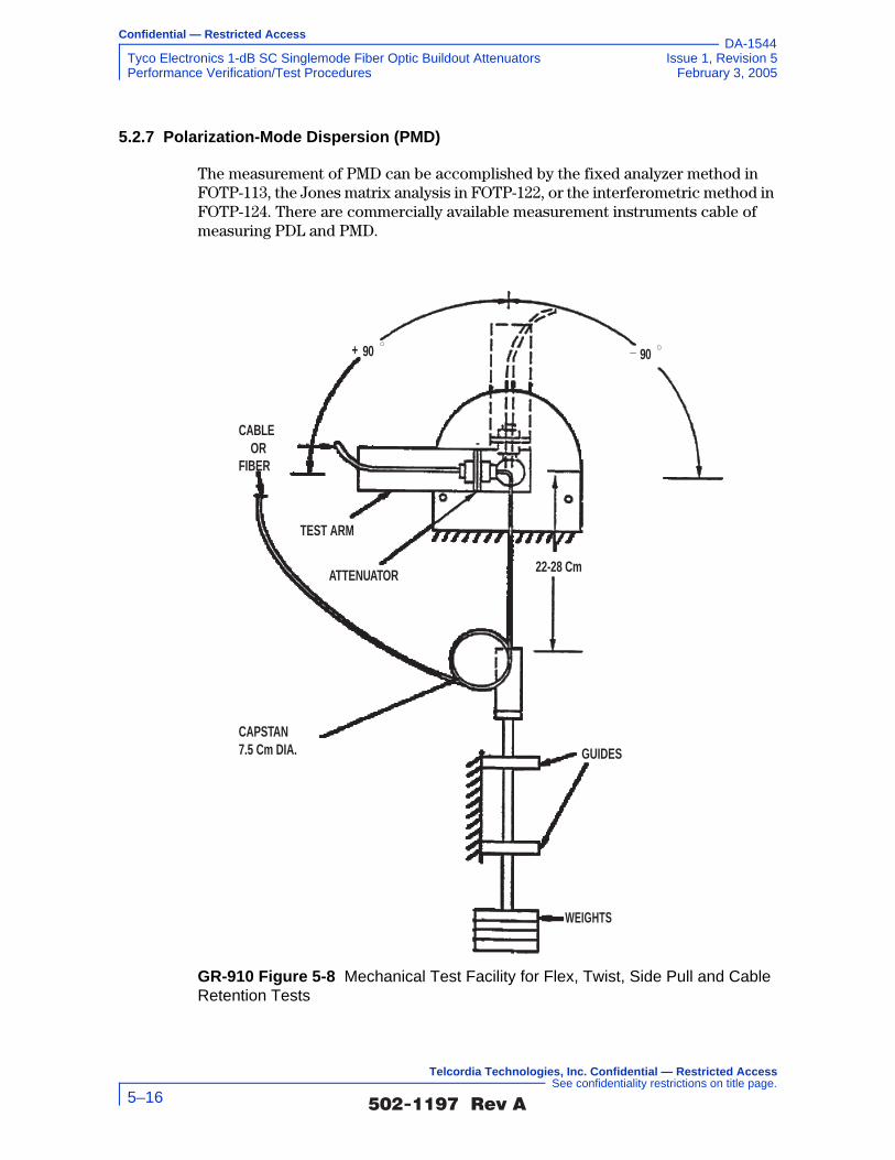
Confidential — Restricted Access
Tyco Electronics 1-dB SC Singlemode Fiber Optic Buildout Attenuators Issue 1, Revision 5Performance Verification/Test Procedures February 3, 2005
DA-1544
5.2.7 Polarization-Mode Dispersion (PMD)
The measurement of PMD can be accomplished by the fixed analyzer method in FOTP-113, the Jones matrix analysis in FOTP-122, or the interferometric method in FOTP-124. There are commercially available measurement instruments cable of measuring PDL and PMD.
GR-910 Figure 5-8 Mechanical Test Facility for Flex, Twist, Side Pull and Cable Retention Tests
WEIGHTS
GUIDES
CAPSTAN7.5 Cm DIA.
ATTENUATOR
TEST ARM
22-28 Cm
CABLE OR
FIBER
90+ 90_
�������� �� 5–16
Telcordia Technologies, Inc. Confidential — Restricted Access See confidentiality restrictions on title page.

Confidential — Restricted Access
Issue 1, Revision 5 Tyco Electronics 1-dB SC Singlemode Fiber Optic Buildout AttenuatorsFebruary 3, 2005 Passive Optical Component Code (POCC)
DA-1544
6.0 Passive Optical Component Code (POCC)
6.1 Structure and Format
The Passive Optical Component Code is the Telcordia proposed descriptive code which offers1 a quick reference to mechanical, electrical, and optical definitions in a minimum number of characters. To accommodate LEC and service provider procurement system software, the code length must not exceed 15 characters.
GR-910 O6-1 [74] The Passive Optical Component Code (POCC) characters as outlined in GR-910 Table 6-1 should be imprinted on the component housing.
The code has two fields,
M1M2 − S1S2S3 A S4S5S6 S7S8S9S10S11S12
The first field, M1M2, is a manufacturer code. The following table lists the cable manufacturer codes assigned by Telcordia based upon lists of manufacturers provided to Telcordia by regions, LECs, and other service providers. The list is not necessarily complete. There may be other manufacturers of similar products who are not listed. No recommendation for or against any manufacturer is intended or should be inferred from its presence or absence from this list. The list includes only attenuator manufacturers.2
1. The POCC was adopted from SR-NWT-002014, Suggested Optical Cable Code (SOCC).
2. The following codes should be avoided as they are assigned to fiber cable and/or other component manufacturers; BC, BI, BR, BT, CW, DI, DN, EB, EC, FG, GC, GS, LC, MC, OC, PC, PK, SR, SP, TF, TN.
�������� �� 6–1
Telcordia Technologies, Inc. Confidential — Restricted Access See confidentiality restrictions on title page.

Confidential — Restricted Access
Tyco Electronics 1-dB SC Singlemode Fiber Optic Buildout Attenuators Issue 1, Revision 5Passive Optical Component Code (POCC) February 3, 2005
DA-1544
Any manufacturers not on this list but who would like to be placed on it should contact the appropriate region, LEC, service provider, or Telcordia.
GR-910 Table 6-1 Passive Optical Component Manufacturer Code POCC
Code Manufacturer Code Manufacturer
3M 3M ME Methode Electronics Inc.
AD ADC Telecommunications MO Molex Fiber Optic Interconnect TechnologyAF Alcoa-Fujikura
AI ATI MP MP Fiber Optics Inc,
AM Amphenol NE NEC Electronics
AO AOFR NS NSG America
AP AMP NT Northern Telecom
AR Aster OS Optotec Spa
AT AT&T OZ Oz Optics
CO Corning PD PD-LD Inc.
EB E x B Technology Inc, PO Physical Optics
ER Ericsson Components PS Porta Systems
ET E-TEK Dynamics RL Radiall
FE Furukawa Electric Co. Ltd. RC Radiant Communications Corp,
FN Fiber Network Solutions RS Rifocs
FS Fibersense & Signals SA Santec Corp.
FU Fujikura Ltd. SD Storm Products
FX Foxconn International Inc, SE Sumitomo Electric
GD Gould SM Sifam Ltd. (Selco)
IP Ipitek SO Seiko
JF JDS-Fitel (Furukawa) SR Siecor
LS Light Control Systems SS Siemens Stromburg-Carlson
�������� �� 6–2
Telcordia Technologies, Inc. Confidential — Restricted Access See confidentiality restrictions on title page.
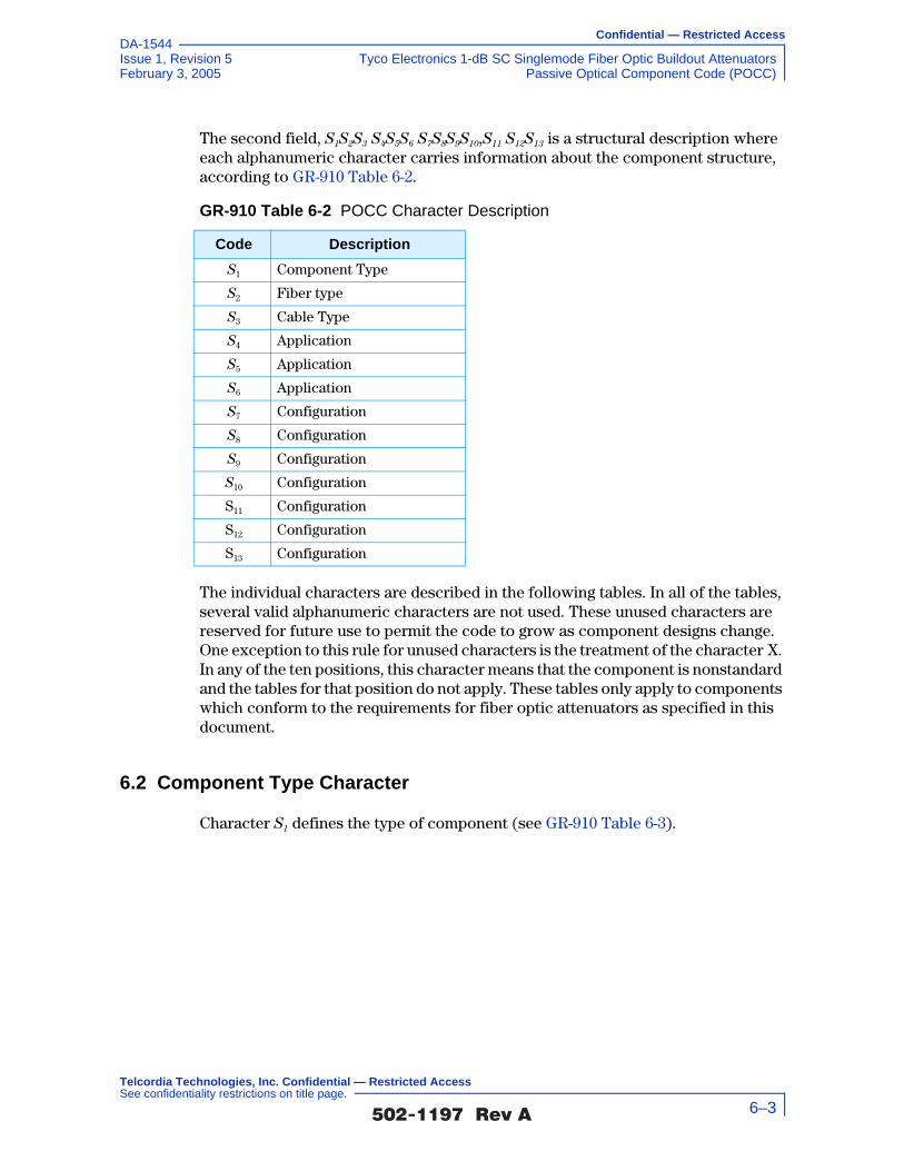
Confidential — Restricted Access
Issue 1, Revision 5 Tyco Electronics 1-dB SC Singlemode Fiber Optic Buildout AttenuatorsFebruary 3, 2005 Passive Optical Component Code (POCC)
DA-1544
The second field, S1S2S3 S4S5S6 S7S8S9S10,S11 S12S13 is a structural description where each alphanumeric character carries information about the component structure, according to GR-910 Table 6-2.
The individual characters are described in the following tables. In all of the tables, several valid alphanumeric characters are not used. These unused characters are reserved for future use to permit the code to grow as component designs change. One exception to this rule for unused characters is the treatment of the character X. In any of the ten positions, this character means that the component is nonstandard and the tables for that position do not apply. These tables only apply to components which conform to the requirements for fiber optic attenuators as specified in this document.
6.2 Component Type Character
Character S1 defines the type of component (see GR-910 Table 6-3).
GR-910 Table 6-2 POCC Character Description
Code Description
S1 Component Type
S2 Fiber type
S3 Cable Type
S4 Application
S5 Application
S6 Application
S7 Configuration
S8 Configuration
S9 Configuration
S10 Configuration
S11 Configuration
S12 Configuration
S13 Configuration
�������� �� 6–3
Telcordia Technologies, Inc. Confidential — Restricted Access See confidentiality restrictions on title page.

Confidential — Restricted Access
Tyco Electronics 1-dB SC Singlemode Fiber Optic Buildout Attenuators Issue 1, Revision 5Passive Optical Component Code (POCC) February 3, 2005
DA-1544
6.3 Fiber Type and Operating Wavelength Region Character
S2 defines the fiber type (e.g., single-mode) and the usable wavelengths (i.e., the wavelengths at which the component may operate). For components with no fiber pigtails, S2 only indicates the component's usable wavelength region. See GR-910 Table 6-4.
The 1480-1580 and 980-1550 columns apply to components for use with optical fiber amplifiers.
6.4 Cable Type Character
Character S3, describes the cable or fiber jacket type (GR-910 Table 6-5).
GR-910 Table 6-3 POCC Character S1
Code Component
A Attenuator
B Connector
C Coupler
F Filter
I Isolator
P Polarizer
S Switch
T Terminator
W WDM
GR-910 Table 6-4 POCC Character S2
Fiber Type
Usable Wavelength Regions (nm) and Codes
850 1300850 -1300
1310 15501310 -1550
1480 -1580
980 -1550
Single-Mode Class IVa - - 0 1 2 3 4 5
Dispersion-Shifted Class IVb - - - - 6 7 8 9
Hybrid Class IVa-50/125 A B C D E F G H
50/125 Multimode K L M - - - - -
62.5/125 Multimode P Q R - - - - -
85/125 Multimode T W Y - - - - -
�������� �� 6–4
Telcordia Technologies, Inc. Confidential — Restricted Access See confidentiality restrictions on title page.

Confidential — Restricted Access
Issue 1, Revision 5 Tyco Electronics 1-dB SC Singlemode Fiber Optic Buildout AttenuatorsFebruary 3, 2005 Passive Optical Component Code (POCC)
DA-1544
6.5 Attenuation Value Characters
These characters are keyed to the Component Type S1 character, so that the meaning of S4S5S6S7 may change for different components. For attenuators (S1 = A), S4S5S6 S7 is a 3-digit integer from 1 to 100 defining the attenuation value for a fixed attenuator or the minimum and maximum values for a variable attenuator in dB.
6.6 Application Character
S8 defines applications for which the component is designed (GR-910 Table 6-6).
Refer to GR-253-CORE for definitions of long-reach systems.
6.7 Configuration Characters
Characters S9-12 are keyed to the Component Type S1 character, so that their meaning may change for different components. For attenuators (S1 = A), S 9-
10 indicate the reflectance value of the attenuator ranging from 1 to 99. S11 S12 describe the optical connector type.
GR-910 Table 6-5 POCC Character S3
Code Cable Type
B Fiber Bundle
L Loose Buffer
M Flat Matrix
R Ribbon
S Standard Coated Fiber (250 µm nominal)
T Tight Buffer
3 Ruggedized- 3 mm dia.
GR-910 Table 6-6 POCC Character S8
Code Application
A AM-VSB Analog Systems Only
D Digital Systems Only
H Hybrid - for both Analog & Digital Systems
L Long-Reach Digital Systems Only
�������� �� 6–5
Telcordia Technologies, Inc. Confidential — Restricted Access See confidentiality restrictions on title page.

Confidential — Restricted Access
Tyco Electronics 1-dB SC Singlemode Fiber Optic Buildout Attenuators Issue 1, Revision 5Passive Optical Component Code (POCC) February 3, 2005
DA-1544
For example, for an attenuator with 40 dB reflectance and FC connectors S9S10S11S12 = 40FF.
6.8 Example
The POCC WD-A3S 520140FF is interpreted as shown in GR-910 Table 6-7.
GR-910 Table 6-7 POCC Interpretation
Character Value Interpretation
M1M2 WD Manufacturer is Widget Inc.
S1 A Component is a an Attenuator
S2 3 Fiber is 1310-1550 nm single-mode
S3 S Fiber is 250 µm coated
S4S5S6S7 5201 Attenuation is variable 5-20 ± 1 dB
S8 D Attenuator is for digital system applications
S9-12 40FF R=40 dB FC connectors
�������� �� 6–6
Telcordia Technologies, Inc. Confidential — Restricted Access See confidentiality restrictions on title page.

Confidential — Restricted Access
Issue 1, Revision 5 Tyco Electronics 1-dB SC Singlemode Fiber Optic Buildout AttenuatorsFebruary 3, 2005 Reliability and Quality Assurance Program
DA-1544
7.0 Reliability and Quality Assurance Program
This section treats reliability and quality (R&Q) for optical attenuators from the same perspective as other fiber optic passive components. Thus, it deals with the overall assembled unit, manufacturing reliability, and other topics. Major points in a minimum R&Q program are briefly discussed here, with details to be referenced in GR-1221-CORE.
The criteria here are not meant to prevent a manufacturer from using alternative approaches if testing of the assembled unit (e.g., used in a complete optical attenuator package) and pass/fail criteria are at least as stringent as the methods described here. Alternatives will also be necessary for future fully integrated designs in which functionality is provided in a single “plug- and-play” adjunct (to the platform transport system) that does not have any field-replaceable parts.
The philosophy and basic elements of reliability assurance are provided in Section 7.1 and Section 7.2. The qualification and lot-to-lot controls criteria for optical attenuators are detailed in Section 7.3. Section 7.4 contains criteria used if a quality and reliability audit is performed.
7.1 Reliability Assurance Requirements Philosophy
Many of the criteria in this GR deal with necessary elements of a comprehensive reliability assurance program; as such, they are clearly satisfied or not by the component manufacturer's and/or equipment supplier's practices. However, many other criteria deal with demonstration of device reliability or with levels of confidence. The intent of these latter requirements and objectives can sometimes be accomplished in alternative ways. While the qualification tests and screening procedures in this GR have been developed to establish an appropriate baseline for a comprehensive reliability assurance program, other techniques could prove to be more cost-effective. However, this does not suggest that the Telcordia criteria contained here can be satisfied by any other approach.
The difficulty of such alternative approaches involves the demonstration by the manufacturer or supplier of their equivalency or effectiveness. Although certain general guidelines can be described, specific steps to demonstrate this cannot be determined in advance for every situation. Nevertheless, manufacturers and suppliers are encouraged to investigate “improved” test methods and practices. To avoid problems and possible disagreement later, Telcordia can be contacted to resolve most questions prior to significant expenditures in special equipment or testing by the manufacturer or supplier.
7.2 Overview of Reliability Assurance
Unlike functional or performance generic requirements, reliability assurance criteria are seldom “yes or no” issues. There could be many ways of achieving the
�������� �� 7–1
Telcordia Technologies, Inc. Confidential — Restricted Access See confidentiality restrictions on title page.

Confidential — Restricted Access
Tyco Electronics 1-dB SC Singlemode Fiber Optic Buildout Attenuators Issue 1, Revision 5Reliability and Quality Assurance Program February 3, 2005
DA-1544
same end goal of reliable optical attenuators for use in a LEC or service provider telecommunications network. The following sections first describe the tenets of a comprehensive reliability assurance program, and then discuss the philosophy behind the approach taken in this GR.
The basic reliability of fiber optic systems can be no better than the reliability of the components contained in them. Moreover, it is generally impossible to thoroughly test the performance and reliability of components once they are incorporated into higher levels of assembly. It thus becomes necessary for product manufacturers and equipment suppliers to set up programs at the component level to help ensure necessary device reliability.
The major elements of a comprehensive reliability assurance program are:
• Vendor Qualification Programs
• Component Qualification Programs
• Lot-to-Lot Quality and Reliability Controls
• Feedback and Corrective Action Programs
• Storage and Handling
• Documentation.
The critical nature of optical attenuators, plus the rapid evolution of designs and manufacturing practices, make such a program particularly important. The devices used in a telecommunications system should be initially qualified and purchased only from approved vendors. The reliability and quality of each lot should be tested and analyzed. Any problem detected in the manufacturing processes or reported from field applications should be examined and corrected. This information should be fed back as the inputs for vendor and product qualification. Products should also be stored properly, avoiding excessive heat and humidity. Finally, the reliability assurance program should be fully documented to ensure consistency and continuity. The elements of a complete reliability assurance program are depicted in GR-910 Figure 7-1.
�������� �� 7–2
Telcordia Technologies, Inc. Confidential — Restricted Access See confidentiality restrictions on title page.
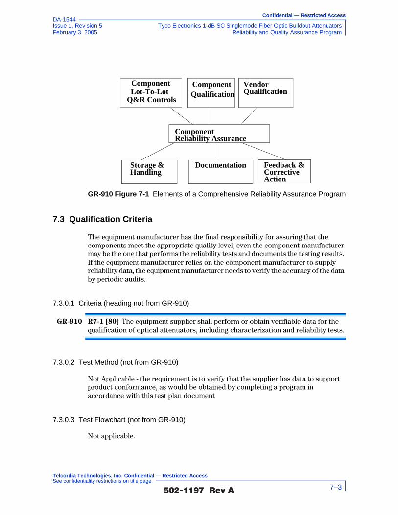
Confidential — Restricted Access
Issue 1, Revision 5 Tyco Electronics 1-dB SC Singlemode Fiber Optic Buildout AttenuatorsFebruary 3, 2005 Reliability and Quality Assurance Program
DA-1544
7.3 Qualification Criteria
The equipment manufacturer has the final responsibility for assuring that the components meet the appropriate quality level, even the component manufacturer may be the one that performs the reliability tests and documents the testing results. If the equipment manufacturer relies on the component manufacturer to supply reliability data, the equipment manufacturer needs to verify the accuracy of the data by periodic audits.
7.3.0.1 Criteria (heading not from GR-910)
GR-910 R7-1 [80] The equipment supplier shall perform or obtain verifiable data for the qualification of optical attenuators, including characterization and reliability tests.
7.3.0.2 Test Method (not from GR-910)
Not Applicable - the requirement is to verify that the supplier has data to support product conformance, as would be obtained by completing a program in accordance with this test plan document
7.3.0.3 Test Flowchart (not from GR-910)
Not applicable.
GR-910 Figure 7-1 Elements of a Comprehensive Reliability Assurance Program
Component Reliability Assurance
Vendor Qualification
Component Qualification
ComponentLot-To-Lot
Q&R Controls
Storage &Handling
Documentation Feedback &Corrective Action
�������� �� 7–3
Telcordia Technologies, Inc. Confidential — Restricted Access See confidentiality restrictions on title page.

Confidential — Restricted Access
Tyco Electronics 1-dB SC Singlemode Fiber Optic Buildout Attenuators Issue 1, Revision 5Reliability and Quality Assurance Program February 3, 2005
DA-1544
7.3.0.4 Test Configuration and Conditions (not from GR-910)
Not applicable.
7.3.0.5 Test Apparatus (not from GR-910)
Not applicable.
7.3.0.6 Summary of Test Results (not from GR-910)
Conformance/Nonconformance
Conformance to the criteria in Section 7.3.0.1 of this document has not been met. The criteria for requirement GR-910 R7-1 [80] was not determined. Conformance is based on the equipment supplier performing or obtaining verifiable data for the qualification of optical attenuators, including characterization and reliability tests
Failure History
Not applicable.
Disposition of Nonconformance
Not applicable.
Test Data
Not applicable.
7.3.1 Characterization
7.3.1.1 Criteria (heading not from GR-910)
Several acronyms are used in the detailed tables for device qualification. “LTPD” refers to Lot Tolerance Percent Defective as described in Appendix B of Military Specification MIL-M-38510F or in Appendix C of MIL-S-19500G.1 “SS” refers to a suggested sample size appropriate for the specified LTPD. “C” indicates the maximum number of failures allowed for that sample size.
GR-910 R7-2 [81] Optical attenuators shall be fully characterized for optical performance as part of device qualification. The characterization must include mechanical, electrical, and optical parameters. A sample size of at least 11 devices (LTPD of 20%) is required. A failure is defined as any component that does not meet all the specified parametric limits.
1. The same information also may be found in Appendix A of IEC Pub. 747-10.
�������� �� 7–4
Telcordia Technologies, Inc. Confidential — Restricted Access See confidentiality restrictions on title page.

Confidential — Restricted Access
Issue 1, Revision 5 Tyco Electronics 1-dB SC Singlemode Fiber Optic Buildout AttenuatorsFebruary 3, 2005 Reliability and Quality Assurance Program
DA-1544
Because of varieties of optical attenuator designs, the minimum set of parameters for characterization is not included here. To avoid cost and poor reliability that might occur later, Telcordia can be contacted for discussions to reach a consensus on the parameters to be characterized.
GR-910 O7-3 [82] Optical attenuators data also should be obtained from the vendor (in-house or external) on a much larger population (~ 50-200 units representing a minimum of three different date codes). Distributions (minimum, maximum, mean, and 3σ) of measured parameters should be compared to specification limits and design requirements to assure that adequate margins exist.
7.3.1.2 Test Method (not from GR-910)
1. Determine the appropriate specification for attenuator characterization and use the test procedures defined for selected parameters specific to the attenuator under test
2. Verify that the test procedures address mechanical, environmental and optical performance characteristics, such as optical bandpass, change in attenuation, attenuation tolerance, attenuation increments and range, reflectance and PDL, and PMD.
3. Verify that the sample size for test is at least 11 devices (LTPD of 20%), unless otherwise specified by the end user (and if otherwise specified, fully document any such deviation)
4. Analyze the characterization data obtained in accordance with the requirements specific to the product under test and verify conformance, as well as documenting any deviation from the criteria
5. Analyze vendor data on broader samplings of component performance characteristics to assess the distribution of measured parameters to assure adequate measurement margins are in evidence
�������� �� 7–5
Telcordia Technologies, Inc. Confidential — Restricted Access See confidentiality restrictions on title page.
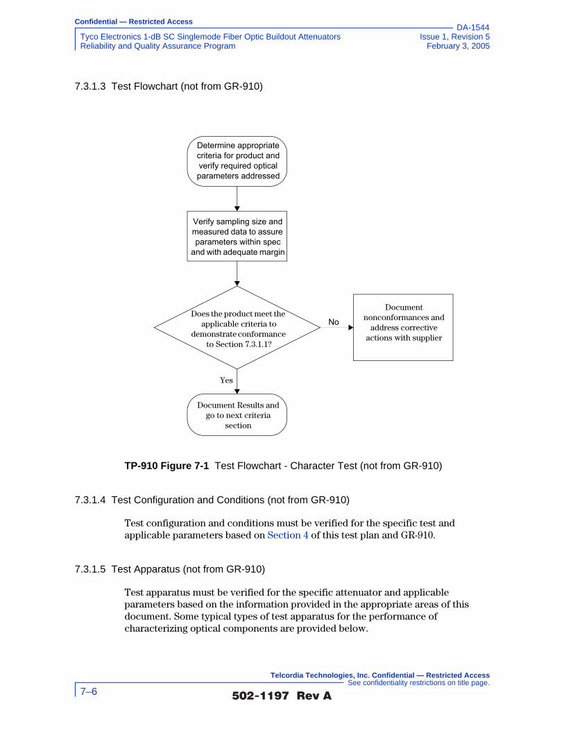
Confidential — Restricted Access
Tyco Electronics 1-dB SC Singlemode Fiber Optic Buildout Attenuators Issue 1, Revision 5Reliability and Quality Assurance Program February 3, 2005
DA-1544
7.3.1.3 Test Flowchart (not from GR-910)
7.3.1.4 Test Configuration and Conditions (not from GR-910)
Test configuration and conditions must be verified for the specific test and applicable parameters based on Section 4 of this test plan and GR-910.
7.3.1.5 Test Apparatus (not from GR-910)
Test apparatus must be verified for the specific attenuator and applicable parameters based on the information provided in the appropriate areas of this document. Some typical types of test apparatus for the performance of characterizing optical components are provided below.
TP-910 Figure 7-1 Test Flowchart - Character Test (not from GR-910)
Does the product meet the applicable criteria to
demonstrate conformance to Section 7.3.1.1?
Document Results and go to next criteria
section
Document nonconformances and
address corrective actions with supplier
Yes
Determine appropriate criteria for product and verify required optical parameters addressed
Verify sampling size and measured data to assure parameters within spec
and with adequate margin
No
�������� �� 7–6
Telcordia Technologies, Inc. Confidential — Restricted Access See confidentiality restrictions on title page.

Confidential — Restricted Access
Issue 1, Revision 5 Tyco Electronics 1-dB SC Singlemode Fiber Optic Buildout AttenuatorsFebruary 3, 2005 Reliability and Quality Assurance Program
DA-1544
7.3.1.6 Summary of Test Results (not from GR-1221)
Conformance/Nonconformance
Conformance to the criteria in Section 7.3.1.1 of this document has not been met. The criteria for requirements GR-910 R7-2 [81] and GR-910 O7-3 [82] were not determined. Conformance is based on the optical attenuators being fully characterized for optical performance as part of device qualification.
Failure History
Not applicable.
Disposition of Nonconformance
Not applicable.
Test Data
Not applicable.
7.3.2 Reliability Tests
7.3.2.1 Criteria (heading not from GR-910)
GR-910 R7-4 [83] Reliability tests for optical attenuators shall include mechanical/physical tests as well as endurance tests. … Table 1 lists a minimum set of tests that must be performed.
GR-910 R7-5 [84] Mechanical/optical performance tests shall be completed before and after each of the reliability tests. Out of specifications shall be counted as failures. Other pass/fail criteria, based on degradations in some key parameters, shall be documented along with the testing methods.
Description Supplier ModelCalibration Cycle
Calibration Due Date.
Optical Tunable Light Source Agilent 8164A 12 months –
Sensor for Tunable Multimeter Agilent 81640A 12 months –
Broadband Stabilized Light Source
Anritsu MG 922 A 12 months –
Optical Spectrum Analyzer Anritsu MS 9710 B 12 months –
�������� �� 7–7
Telcordia Technologies, Inc. Confidential — Restricted Access See confidentiality restrictions on title page.

Confidential — Restricted Access
Tyco Electronics 1-dB SC Singlemode Fiber Optic Buildout Attenuators Issue 1, Revision 5Reliability and Quality Assurance Program February 3, 2005
DA-1544
Different groups of sample devices may be used for each test or the same sample may be used for several tests, but the manufacturer must be aware that any failures due to the cumulative degradation carried over from one test to the next shall be counted as failures.
The conditional requirements in … Table 1 need only be conducted for uncontrolled
environment applications. Different time and temperature combinations may be chosen by the supplier if the alternate test conditions are shown to be at least as effective as those in this document. This often involves the use of models for calculating an acceleration factor. Intrinsic failure mechanisms are defined as the type modeled by the Arrhenius relationship (such as chemical reactions or processes involving diffusion). Extrinsic failure mechanisms are characterized by
… Table 1 (R) Required Reliability Tests
Test Standard ConditionsSampling
[LTPD]Criterion
Mech. Shock EIA/TIA-455-2A 1.8 meters, 5 cycles
20% R
Vibration EIA/TIA-455-11A 20G, 10-2,000 Hz 20% R
Thermal Shock EIA/TIA-455-71 ∆T=100oC, 20 cycles
20% R
High Temperature Aging (dry)
MIL-STD-883-D, Method 1005,
85oC, <40%RH, 5000 hrs-qualif. 10,000 hrs-info. dynamically exercised
10% R
High Temperature Storage (damp)
EIA/TIA-455-5A 75oC, 90%RH 2000 hrs-qualif. 5000 hrs-info.
10% R
Low Temperature Storage EIA/TIA-455-4A -40oC, 2500 hrs-qualif. 5000 hrs-info.
20% CR*
Temp. Cycling EIA/TIA-455-3A or MIL-STD-883D Method 1010
-40 to 75oC, 500 cycles-qualif. 1000 cycles-info.
20% R
Temp./Humidity Cycling IEC 68-2-38 -40 to 75oC, 5 cycles
20% CR
Salt Spray EIA/TIA-455-16A 20% CR
Water Immersion EIA/TIA-455-12A 20% CR
Airborne Contaminants ASTM B827-92 5 devices CR
* CR indicates a Conditional Requirement that is only necessary for products intended for uncontrolled environments, except for Airborne Contaminants where CR indicates that this test applies to specific products - see Section 4.
�������� �� 7–8
Telcordia Technologies, Inc. Confidential — Restricted Access See confidentiality restrictions on title page.

Confidential — Restricted Access
Issue 1, Revision 5 Tyco Electronics 1-dB SC Singlemode Fiber Optic Buildout AttenuatorsFebruary 3, 2005 Reliability and Quality Assurance Program
DA-1544
threshold-type failures, such as those resulting from mechanical impact, bending or applied tension - in such cases, it is not appropriate to use the Arrhenius relationship. The relative humidity is another important stress factor and its acceleration factor has not been generally agreed upon in the industry. Any questions on this need to be resolved prior to any extensive reliability testing.
GR-910 R7-6 [85] Technical justification of the acceleration aging factors by stresses, such as temperature, humidity, or optical power, for different testing conditions is required. Associated acceleration/deceleration factors must be clearly identified.
Some of the commercially available products in the market today are not hermetically sealed. For these components, the liquid-to-liquid thermal shock test might not be appropriate. However, additional tests are recommended if these non-hermetic components are to be used in non-central office (CO) environments.
GR-910 R7-7 [86] For those components with non-hermetic packages, the thermal shock test will not be required, but the damp heat testing duration must be increased to 5000 hours from the 2000 hour test for hermetic components.
The object of the dry and damp heat tests is to assess the effects of temperature and humidity on the expected operating life of the component. In addition to the thermal activation energy, the presence of water vapor at an elevated temperature produces an accelerated aging effect.
GR-910 R7-8 [87] If technical data are not available in support of other values, an activation energy of 0.3 eV shall be assumed for the dry heat test and an effective activation energy of 0.6 eV shall be assumed for the damp heat test. In the latter case, the higher activation energy accounts for the difference between the test's high humidity and “average” operating conditions, such that a separate term for humidity would not be included in the calculation of the acceleration factor.
Manufacturers may use a different activation energy or a different model for calculating acceleration, if its use can be supported by empirical data. The empirical data must be based on reliability testing or field returns, and shall be available for review by the LECs, service providers or their representative.
There is very limited information on activation energies for optical attenuators. The above values represent a conservative assumption and will be modified as more data become available.
To demonstrate different acceleration models or activation energies, a matrix of multiple temperatures and humidities would provide the most thorough understanding (see GR-910 Table 7-1). However, as a minimum, or as the first tests performed, three specific sets of conditions are usually required:
�������� �� 7–9
Telcordia Technologies, Inc. Confidential — Restricted Access See confidentiality restrictions on title page.

Confidential — Restricted Access
Tyco Electronics 1-dB SC Singlemode Fiber Optic Buildout Attenuators Issue 1, Revision 5Reliability and Quality Assurance Program February 3, 2005
DA-1544
GR-910 O7-9 [88] In order of priority, the following life tests should be performed as part of any effort to validate alternative acceleration models or activation energies:
1. High temperature damp heat = 75°C, 90% RH (or 85°C, 85% RH)
2. High temperature dry heat = 85°C, ~ 16% RH
3. Moderate temperature damp heat = 45°C, 85% RH
Minimum sample size is 22 devices for each life test. Results should include estimates of median life or mean-time-to-failure (MTTF), and a “spread” parameter (e.g., standard deviation).
The purpose of the temperature cycling life test is to demonstrate the long-term mechanical stability of the package.
GR-910 R7-10 [89] A temperature cycle life test shall be performed in accordance with the procedures of Section 6.2.7 in GR-1221-CORE. The minimum and maximum temperatures shall be at least − 40°C and + 75°C. The minimum sample size is 11 devices (LTPD of 20%). Results after 500 cycles shall be used for “passing” or “failing” the test. Failures between 500 cycles and 1000 cycles shall be investigated and corrective actions shall be implemented.
GR-910 R7-11 [90] Fiber pigtails and optical connectors shall comply with general flammability requirements for materials used in telecommunications systems.
Detailed flammability criteria are given in GR-78-CORE and TR-NWT-000357. For packages made of metal, glass or ceramic, destructive flammability testing is not
GR-910 Table 7-1 Test Matrix for Demonstrating Acceleration Factors [Relative Humidity as a Function of Temperature and Absolute Humidity]
Absolute Humidity [gm/
m3]
Temperature [°C]
25 40 45 55 65 75 85 95
19.2 85 38 30 19 12 8 6 4
42.5 sat 85 67 42 27 18 12 9
54.0 sat 85 53 34 23 16 11
86.0 sat 85 55 37 25 18
134.0 sat 85 57 39 27
200.0 sat 85 58 41
211.0 90 61 43
293.0 sat 85 60
419.0 sat 85
�������� �� 7–10
Telcordia Technologies, Inc. Confidential — Restricted Access See confidentiality restrictions on title page.

Confidential — Restricted Access
Issue 1, Revision 5 Tyco Electronics 1-dB SC Singlemode Fiber Optic Buildout AttenuatorsFebruary 3, 2005 Reliability and Quality Assurance Program
DA-1544
required. However, a statement that the module (excluding the fiber optic pigtail) will not support combustion and is capable of passing component flammability requirements2 may be requested. Flammability testing of packages having external epoxy, silicone or other organic materials is required.
7.3.2.2 Test Method (not from GR-910)
1. Verify that supplier subjects their components to mechanical/physical tests for reliability such as those described in … Table 1 (and as described in Section 4 of this test plan which fully details the requirements and methods to be followed in the performance of mechanical/physical tests).
2. Verify that optical performance testing is included in any reliability testing, and that the test programs specify performance measurements be made both before and after the test, and that test results are analyzed against the product specific criteria documented for the particular product under test.
3. If alternate testing methods for accelerated aging, specifying alternate activation energies, then analyze and verify the technical data and rationale which justifies the use of such alternatives. Verify that a minimum of 22 samples is used as part of the justification test data.
4. Verify that for those components with non-hermetic packages, the thermal shock test is not performed (as it is not required for that case), but the damp heat testing duration has been increased to 5000 hours from the 2000 hour test for hermetic components
5. Verify that thermal cycling tests per Section 6.2.7 in GR-1221-CORE are performed and any non-conformance are documented and addressed for proposed corrective actions.
6. Verify that fiber pigtails and optical connectors comply with general flammability requirements for materials used in telecommunications systems.
2. See Section 4.4.2.5 of TR-NWT-000357.
�������� �� 7–11
Telcordia Technologies, Inc. Confidential — Restricted Access See confidentiality restrictions on title page.

Confidential — Restricted Access
Tyco Electronics 1-dB SC Singlemode Fiber Optic Buildout Attenuators Issue 1, Revision 5Reliability and Quality Assurance Program February 3, 2005
DA-1544
7.3.2.3 Test Flowchart (not from GR-910)
7.3.2.4 Test Configuration and Conditions (not from GR-910)
Not Applicable - this section requires verifying that tests are performed such as those described in Section 4 of this document. Section 4 contains the details on test configuration, conditions and apparatus appropriate to the specified tests.
TP-910 Figure 7-2 Test Flowchart - Reliability Test (not from GR-910)
Does the product meet the applicable criteria to
demonstrate conformance to Section 7.3.2.1 criteria?
Document Results and go to next criteria
section
Document nonconformances and
address corrective actions with supplier
Yes
Verify appropriate reliability tests are
performed and optical parameters measured
Use test results and analysis to validate any
alternative methodologies used in
reliability tests
No
�������� �� 7–12
Telcordia Technologies, Inc. Confidential — Restricted Access See confidentiality restrictions on title page.

Confidential — Restricted Access
Issue 1, Revision 5 Tyco Electronics 1-dB SC Singlemode Fiber Optic Buildout AttenuatorsFebruary 3, 2005 Reliability and Quality Assurance Program
DA-1544
7.3.2.5 Test Apparatus (not from GR-910)
Not Applicable - this section requires verifying that tests are performed such as those described in Section 4 of this document. Section 4 contains the details on test configuration, conditions and apparatus appropriate to the specified tests.
7.3.2.6 Summary of Test Results (not from GR-910)
Conformance/Nonconformance
Conformance to the criteria in Section 7.3.2.1 of this document has not been met. The criteria for requirements GR-910 R7-4 [83], GR-910 R7-5 [84], GR-910 R7-6 [85], GR-910 R7-7 [86], GR-910 R7-8 [87], GR-910 O7-9 [88], GR-910 R7-10 [89] and GR-910 R7-11 [90] were not determined. Conformance is based on the verification that the supplier has subjected their components to the mechanical/physical tests for reliability as described in Section 4, verification that optical performance testing is included in any reliability testing, verification that for components with non-hermetic packages the damp heat testing duration has been increased to 5000 hours from the 2000 hour test for hermetic components, verification that thermal cycling tests per Section 6.2.7 in GR-1221-CORE are performed and that any non-conformance are documented and addressed for proposed corrective actions, and verification that fiber pigtails and optical connectors comply with general flammability requirements for materials used in telecommunications systems. If alternate testing methods for accelerated aging are used, conformance is also based on the specification of alternate activation energies as well as the analysis and verification of technical data and rationale to justify the use of such alternatives. A minimum of 22 samples must be used as part of the justification test data.
Failure History
Not applicable.
Disposition of Nonconformance
Not applicable.
Test Data
Not applicable.
7.3.3 Failure Rate Prediction
The failure rate is an important concept and provides useful information for a reliability analysis. TR-332 contains the details on failure rate predictions. The section here provides some specific information on failure rates for optical attenuators.
�������� �� 7–13
Telcordia Technologies, Inc. Confidential — Restricted Access See confidentiality restrictions on title page.

Confidential — Restricted Access
Tyco Electronics 1-dB SC Singlemode Fiber Optic Buildout Attenuators Issue 1, Revision 5Reliability and Quality Assurance Program February 3, 2005
DA-1544
7.3.3.1 Criteria (heading not from GR-910)
GR-910 R7-12 [91] Equivalent time and temperature requirements shall be calculated using the Arrhenius relationship. Technical justification of the activation energy used for different conditions in temperature-dependent life tests is required.
Acceleration models (for failure mechanisms affected by other stresses, such as optical power or humidity) shall be demonstrated (theoretically if possible and empirically). Associated acceleration/deceleration factors must be clearly identified.
A common form of the Arrhenius relationship is given below:
where
T1 and T2 are the temperatures in Kelvin,
ML is the median life at a given temperature,
Ea is the activation energy, and
k is Boltzmann's constant.
To date, the use of the Arrhenius relationship for some failure mechanisms observed in passive components has not been proven. Unless the failure mechanism and associated activation energy can be identified, the data generated using the Arrhenius relationship is recognized as the best estimate. Section 7.3.2 gives default values for activation energies if empirical data are not available.
GR-910 O7-13 [92] The acceleration aging factor from humidity is recommended to be assessed by the equation below. Technical justification of the derivation is required.
where
H1 and H2 are the relative humidity levels in %,
ML is the median life at a given humidity, and
B and n are empirical constants.
GR-910 R7-14 [93] Wear-out and random failure rates and acceleration aging factors shall be provided. The sources and data shall also be provided.
ML T2( )ML T1( )------------------------
Eak
-------- 1T2------- 1
T1-------–
⋅exp=
ML H2( )ML H1( )------------------------- BH1
n BH2n
–[ ]exp=
�������� �� 7–14
Telcordia Technologies, Inc. Confidential — Restricted Access See confidentiality restrictions on title page.

Confidential — Restricted Access
Issue 1, Revision 5 Tyco Electronics 1-dB SC Singlemode Fiber Optic Buildout AttenuatorsFebruary 3, 2005 Reliability and Quality Assurance Program
DA-1544
Wear-out failure rates are usually based on the aging test data obtained during the formal qualification tests. The random failure rates are difficult to be adequately determined solely based on the formal qualification testing data because these data are usually limited and do not provide adequate basis for calculation. To compensate the deficiency, pre-qualification testing data or data from other sources can be used as supplemented database to calculate the random failure rate if they are adequately documented.
Additional detailed reliability prediction procedure is documented in TR-332, in which there are three prediction methods accepted. They are: Method I - parts count; Method II - combining laboratory data with parts count; and Method III - field tracking. It must be understood that adequate reliability assurance practices, as outlined in TR-NWT-000357 and other related documents, provide the foundation for failure rate predictions. Without the basic component reliability programs in design and manufacturing, some failure mechanisms that might be real in the actual field operations may not be included in the base failure rates of components contained in TR-332. Without thorough qualification, field tracking data might be misinterpreted because failure mechanisms and environment stresses are not known. And without lot-to-lot controls, the reliability of the product might have already shifted from those installed in fields. In short, failure rate predictions might be very different from reality if the basic component reliability programs are not in place at the manufacturer. In practice, the failure rate prediction for a specific product is validated during a Telcordia reliability audit, which evaluates manufacturer’s reliability programs against requirements in Telcordia reliability documents. Since optical attenuators are relatively new devices to be deployed in the fiber optic networks, there is virtually no public failure rate information existing today. Besides, there is no standard end-of-life definition for laboratory life tests. Based on very limited preliminary proprietary laboratory testing results, Telcordia estimates the failure rate for optical attenuators to be in the range around 5000 FITs. As technology makes progress and more data becomes available, Telcordia believes the failure rates will come down dramatically to the range where field installation will be practical. At that time, Telcordia will update the failure rates in this document.
GR-910 O7-15 [94] To simplify review (by customers or their representatives) of failure rate predictions, the format in … Table 2 is recommended for use by device manufacturers and/or equipment suppliers.
… Table 2 (O) Sample Format for Reporting Failure Rate Predictions
Item Value
Median Life (ML) @ 40°C years
Standard Deviation (σ)
Wear-Out Failure Rate (λ WO) @ 40°C FITs*
Wear-Out Activation Energy (Ea) eV
�������� �� 7–15
Telcordia Technologies, Inc. Confidential — Restricted Access See confidentiality restrictions on title page.

Confidential — Restricted Access
Tyco Electronics 1-dB SC Singlemode Fiber Optic Buildout Attenuators Issue 1, Revision 5Reliability and Quality Assurance Program February 3, 2005
DA-1544
GR-910 R7-16 [95] The testing data and supporting evidence for … Table 2 shall be documented and available for review at the request of a LEC, service provider or its representative.
… Table 2 is most useful if there is only one dominant failure mechanism, which might not be valid for all component designs and technologies. In addition, the failure rate might vary over time according to the failure distribution, for which there is limited data and currently no consensus candidate. In any case, … Table 2 still provides valuable information for a reliability analysis, and therefore, the information in … Table 2 is recommended to be provided.
GR-910 R7-17 [96] Unless otherwise specified, all failures observed in qualification testing must normally be counted and must be reported, regardless of the failure mode. Omission of any failure from test results must be clearly justified and must be reviewed with the LEC, service provider or its representative.
Although reliability tests are usually designed to detect one type of failure mechanism, other unexpected failure mechanisms often occur as well, and should not be excluded from the test results. Exceptions are accidental damage or extraordinary circumstances, such as a fiber pigtail that is broken due to mishandling.
GR-910 O7-18 [97] … Table 3 provides the recommended format for reporting the status of all reliability tests.
Basis of Predictions (field data, life test, theory)
Random Failure Rate (λ R) @ 40°C FITs*
Random Failure Activation Energy (Ea) eV
Basis of Predictions (field data, life test, theory)
* A FIT is a failure unit equivalent to the number of failures per billion operating hours.
… Table 2 (O) Sample Format for Reporting Failure Rate Predictions
Item Value
… Table 3 (O) Sample Report Format for Reliability Test Status
Test* Date
CompletedSample
SizeNumber of
FailuresTest
Passed?
Mechanical Shock
Vibration
Thermal Shock
�������� �� 7–16
Telcordia Technologies, Inc. Confidential — Restricted Access See confidentiality restrictions on title page.

Confidential — Restricted Access
Issue 1, Revision 5 Tyco Electronics 1-dB SC Singlemode Fiber Optic Buildout AttenuatorsFebruary 3, 2005 Reliability and Quality Assurance Program
DA-1544
Completing this summary table does not relieve the manufacturer or supplier of satisfying the respective requirements for each test nor of reporting the detailed results in a comprehensive report, as described elsewhere in this test plan.
GR-910 R7-19 [98] The testing data and supporting evidence for … Table 3 shall be documented and available for review at the request of a LEC, service provider or its representative.
7.3.3.2 Test Method (not from GR-910)
1. Verify time and temperature requirements are calculated using the Arrhenius relationship. Technical justification of the activation energy used for different conditions in temperature-dependent life tests is required.
2. Verify that acceleration models are demonstrated (theoretically if possible and empirically). Associated acceleration/deceleration factors must be clearly identified.
3. Verify that acceleration aging factors from humidity are assessed by the equation shown. Technical justification of the derivation is required.
4. Verify that wear-out and random failure rates and acceleration aging factors are provided. The sources and data shall also be provided.
5. Verify that to simplify review (by customers or their representatives) of failure rate predictions, the format in … Table 2 is used by device manufacturers and/or equipment suppliers
High Temp. Storage (Dry)
High Temp. Storage (Damp)
Low Temp. Storage
Temp. Cycle Endurance
Temp./Humidity Cycling
Salt Spray
Water Immersion
Airborne Contaminants
… Table 3 (O) Sample Report Format for Reliability Test Status
Test* Date
CompletedSample
SizeNumber of
FailuresTest
Passed?
�������� �� 7–17
Telcordia Technologies, Inc. Confidential — Restricted Access See confidentiality restrictions on title page.

Confidential — Restricted Access
Tyco Electronics 1-dB SC Singlemode Fiber Optic Buildout Attenuators Issue 1, Revision 5Reliability and Quality Assurance Program February 3, 2005
DA-1544
6. Verify that the testing data and supporting evidence for … Table 2 is documented and available for review at the request of a LEC, service provider or its representative
7. Verify that … Table 3 is used as the format for reporting the status of all reliability tests.
7.3.3.3 Test Flowchart (not from GR-910)
TP-910 Figure 7-3 Test Flowchart - Failure Rate Prediction Test (not from GR-910)
Does the product meet the applicable criteria to
demonstrate conformance to Section 7.3.3.1 criteria?
Document Results and go to next criteria
section
Document nonconformances and
address corrective actions with supplier
Yes
No
Verify appropriate reliability tests are
performed and optical parameters measured
Use test results and analysis to validate any
alternative methodologies used in
reliability tests
�������� �� 7–18
Telcordia Technologies, Inc. Confidential — Restricted Access See confidentiality restrictions on title page.

Confidential — Restricted Access
Issue 1, Revision 5 Tyco Electronics 1-dB SC Singlemode Fiber Optic Buildout AttenuatorsFebruary 3, 2005 Reliability and Quality Assurance Program
DA-1544
7.3.3.4 Test Configuration and Conditions (not from GR-910)
Not Applicable - this section requires verifying that tests are performed such as those described in Section 4 of this document and making specified calculations. Section 4 contains the details on test configuration, conditions and apparatus appropriate to the specified tests needed to support these criteria.
7.3.3.5 Test Apparatus (not from GR-910)
Not Applicable - this section requires verifying that tests are performed such as those described in Section 4 of this document. Section 4 contains the details on test configuration, conditions and apparatus appropriate to the specified tests.
7.3.3.6 Summary of Test Results (not from GR-910)
Conformance/Nonconformance
Conformance to the criteria in Section 7.3.3.1 of this document has not been met. The criteria for requirements GR-910 R7-12 [91], GR-910 O7-13 [92], GR-910 R7-14 [93], GR-910 O7-15 [94], GR-910 R7-16 [95], GR-910 R7-17
[96], GR-910 O7-18 [97] and GR-910 R7-19 [98] were not determined. Conformance is based on the verification that the time and temperature requirements are calculated using the Arrhenius relationship, verification that the acceleration models are demonstrated, verification that the acceleration aging factors from humidity are assessed by the equation shown in O7-13 [92], verification that wear-out and random failure rates and acceleration aging factors are provided, verification that the format in … Table 2 is used by device manufacturers and/or equipment suppliers to simplify review of failure rate predictions, verification that the testing data and supporting evidence for … Table 2 is documented and available for review at the request of a LEC, service provider or its representative, and verification that … Table 3 is used as the format for reporting the status of all reliability tests.
Failure History
Not applicable.
Disposition of Nonconformance
Not applicable.
Test Data
Not applicable.
7.3.4 Optical Adhesives
Qualification of optical adhesives is covered in Section 4.3 of GR-1221-CORE.
�������� �� 7–19
Telcordia Technologies, Inc. Confidential — Restricted Access See confidentiality restrictions on title page.

Confidential — Restricted Access
Tyco Electronics 1-dB SC Singlemode Fiber Optic Buildout Attenuators Issue 1, Revision 5Reliability and Quality Assurance Program February 3, 2005
DA-1544
7.3.5 Quality Assurance and Lot Controls
Functional criteria for optical attenuators are contained in Section 4. These same parametric criteria apply to quality assurance (i.e., incoming inspection). Not all devices have to be tested against all of these parameters, as described below.
7.3.5.1 Visual Inspection
7.3.5.1.1 Criteria (heading not from GR-910)
GR-910 R7-20 [99] Incoming lots of optical attenuators shall be visually inspected on at least a sample basis (to be determined in accordance with a statistical sampling plan established by the equipment supplier).
GR-910 O7-21 [100] Visual inspection (or another step in lot acceptance procedures) should check at least for the following:
A. Package condition
B. Required documentation
C. Product appearance/condition
D. Product identification/marking
E. Inspection of connectors or fiber-pigtails.
These inspection criteria are consistent with the items that would be addressed in a quality technology review, as described in Section 7.4.
7.3.5.1.2 Test Method (not from GR-910)
1. Verify the sampling plan/sample numbers in use for the test program
2. Visually inspect incoming lots of components for adherence to the supplier documented quality processes, which in some cases may have additional specifications in accordance with product type specific criteria documents
3. Inspect and assess the following conditions: package condition, inclusion of required documentation, product appearance/condition, product identification/marking, and inspection of connectors or fiber-pigtails.
4. Document the observations and identify any deviations from expected conditions
�������� �� 7–20
Telcordia Technologies, Inc. Confidential — Restricted Access See confidentiality restrictions on title page.

Confidential — Restricted Access
Issue 1, Revision 5 Tyco Electronics 1-dB SC Singlemode Fiber Optic Buildout AttenuatorsFebruary 3, 2005 Reliability and Quality Assurance Program
DA-1544
7.3.5.1.3 Test Flowchart (not from GR-1221)
7.3.5.1.4 Test Configuration and Conditions (not from GR-1221)
Not Applicable
7.3.5.1.5 Test Apparatus (not from GR-1221)
Not Applicable
TP-910 Figure 7-4 Test Flowchart - Visual Inspection Test (not from GR-910)
Does the product meet the applicable criteria to
demonstrate conformance to Section 7.3.5.1.1?
Document Results and go to next criteria
section
Document nonconformances and
address corrective actions with supplier
Yes
No
Determine appropriate criteria for product and verify required quality parameters addressed
Inspect incoming lots of the product to for
condition in accordance with quality process
�������� �� 7–21
Telcordia Technologies, Inc. Confidential — Restricted Access See confidentiality restrictions on title page.

Confidential — Restricted Access
Tyco Electronics 1-dB SC Singlemode Fiber Optic Buildout Attenuators Issue 1, Revision 5Reliability and Quality Assurance Program February 3, 2005
DA-1544
7.3.5.1.6 Summary of Test Results (not from GR-1221)
Conformance/Nonconformance
Conformance to the criteria in Section 7.3.5.1.1 of this document has not been met. The criteria for requirements GR-910 R7-20 [99] and GR-910 O7-21 [100] were not determined. Conformance is based on the verification of the sampling plan/sample numbers in use for the test program, visual inspection of incoming lots of components for adherence to the supplier documented quality processes, and the inspection and assessment of: package condition, inclusion of required documentation, product appearance/condition, product identification/marking, and inspection of connectors or fiber-pigtails.
Failure History
Not applicable.
Disposition of Nonconformance
Not applicable.
Test Data
Not applicable.
7.3.5.2 Optical Testing
The full set of optical characteristics need not be measured on each device, but may be extrapolated from a representative subset of data (the manufacturer must be able to justify the subset chosen). Criteria for ship-to-stock practices are given in Section 5.1.5 of TR-NWT-000357.
7.3.5.2.1 Criteria (heading not from GR-910)
GR-910 R7-22 [101] Parameters specified in Section 4 form the minimum set of optical parameters which must be guaranteed. If 100% testing for this purpose is not performed, adequate data shall be collected and a statistically justified sampling plan must be established. This sampling test program must be approved in writing from the LEC, service provider or its representative.
7.3.5.2.2 Test Method (not from GR-910)
1. Determine the appropriate specification for component performance characterization and use the test procedures from Section 4 as defined for the specified parameters.
�������� �� 7–22
Telcordia Technologies, Inc. Confidential — Restricted Access See confidentiality restrictions on title page.

Confidential — Restricted Access
Issue 1, Revision 5 Tyco Electronics 1-dB SC Singlemode Fiber Optic Buildout AttenuatorsFebruary 3, 2005 Reliability and Quality Assurance Program
DA-1544
2. Verify that the test procedures address optical bandpass, change in attenuation, attenuation tolerance, attenuation increments and range, reflectance and PDL, and PMD.
3. Verify that the sample size for test is at least 11 devices (LTPD of 20%), unless otherwise specified by the end user (and if otherwise specified, fully document any such deviation)
4. Analyze the characterization data obtained in accordance with the requirements specific to the product under test and verify conformance, as well as documenting any deviation from the criteria
7.3.5.2.3 Test Flowchart (not from GR-910)
TP-910 Figure 7-5 Test Flowchart - Optical Test (not from GR-910)
Does the product meet the applicable criteria to
demonstrate conformance to Section 7.3.5.2.1?
Document Results and go to next criteria
section
Document nonconformances and
address corrective actions with supplier
Yes
No
Determine appropriate criteria for product and verify required optical parameters addressed
Verify sampling size and measured data to assure
parameters within specifications
�������� �� 7–23
Telcordia Technologies, Inc. Confidential — Restricted Access See confidentiality restrictions on title page.

Confidential — Restricted Access
Tyco Electronics 1-dB SC Singlemode Fiber Optic Buildout Attenuators Issue 1, Revision 5Reliability and Quality Assurance Program February 3, 2005
DA-1544
7.3.5.2.4 Test Configuration and Conditions (not from GR-910)
Test configuration and conditions must be verified for the specific test and applicable parameters based on Section 4.
7.3.5.2.5 Test Apparatus (not from GR-910)
Test apparatus must be verified for the specific test and applicable parameters based on Section 4. Some typical types of test apparatus for the performance of characterizing optical components are provided below.
7.3.5.2.6 Summary of Test Results (not from GR-910)
Conformance/Nonconformance
Conformance to the criteria in Section 7.3.1.1 of this document has not been met. The criteria for requirement GR-910 R7-4 [83] was not determined. Conformance is based on the verification that the test procedures address optical bandpass, change in attenuation, attenuation tolerance, attenuation increments and range, reflectance and PDL, and PMD. Conformance is also based on the verification that the sample size for testing is at least 11 devices (LTPD of 20%).
Failure History
Not applicable.
Disposition of Nonconformance
Not applicable.
Test Data
Not applicable.
Description Supplier ModelCalibration Cycle
Calibration Due Date.
Optical Tunable Light Source Agilent 8164A 12 months –
Sensor for Tunable Multimeter Agilent 81640A 12 months –
Broadband Stabilized Light Source
Anritsu MG 922 A 12 months –
Optical Spectrum Analyzer Anritsu MS 9710 B 12 months –
�������� �� 7–24
Telcordia Technologies, Inc. Confidential — Restricted Access See confidentiality restrictions on title page.

Confidential — Restricted Access
Issue 1, Revision 5 Tyco Electronics 1-dB SC Singlemode Fiber Optic Buildout AttenuatorsFebruary 3, 2005 Reliability and Quality Assurance Program
DA-1544
7.3.5.3 Stress Screening
Stress screening helps eliminate components which have any instability in the optical alignment of the components or have built-in mechanical stresses due to improper assembly operations.
7.3.5.3.1 Criteria (heading not from GR-910)
GR-910 R7-23 [102] All optical attenuators shall be subjected to a temperature cycle screen. The minimum requirements consist of 10 cycles between temperature limits of at least –40°C and +75°C; if these are outside the component's specifications, the minimum- and maximum-specified storage temperatures shall be used.
GR-910 O7-24 [103] The demonstration of the effectiveness of alternate temperature cycle conditions for screening should include first characterizing devices after the proposed number of temperature cycles and again after 10 cycles, presumably showing that no significant degradation nor additional failures occurred. The demonstration should be proved on adequate samples over multiple lots.
GR-910 O7-25 [104] All optical attenuators should be subjected to a temperature humidity screen. The minimum requirement is 72 hours at +75°C and 90% RH.
GR-910 R7-26 [105] Optical criteria shall be measured before and after screening. Any “major” changes (as defined and documented by the equipment supplier, in addition to pass/fail criteria) shall result in rejection of a device.
GR-910 O7-27 [106] The pass/fail criteria should be no more than 20% changes on the specified parameters.
GR-910 O7-28 [107] The manufacturer should record the optical criteria before and after screening on a sample of components as a production audit.
7.3.5.3.2 Test Method (not from GR-910)
1. Determine the appropriate specification for component performance characterization and use the test procedures from Section 4 as defined for the specified parameters.
2. Verify that the test procedures address optical bandpass, change in attenuation, attenuation tolerance, attenuation increments and range, reflectance and PDL, and PMD.
3. Verify that temperature cycling testing is performed in accordance with the test parameters as described above. Alternatively, the criteria and test method
�������� �� 7–25
Telcordia Technologies, Inc. Confidential — Restricted Access See confidentiality restrictions on title page.

Confidential — Restricted Access
Tyco Electronics 1-dB SC Singlemode Fiber Optic Buildout Attenuators Issue 1, Revision 5Reliability and Quality Assurance Program February 3, 2005
DA-1544
described in GR-1221, Section 6.2.7 may be used with an additional parameter measurements added after completion of 10 cycles.
4. Analyze the characterization data obtained in accordance with the requirements specific to the product under test and verify conformance, as well as documenting any deviation from the criteria
7.3.5.3.3 Test Flowchart (not from GR-910)
TP-910 Figure 7-6 Test Flowchart - Stress Screening Test (not from GR-910)
Does the product meet the applicable criteria to
demonstrate conformance to Section 7.3.5.3.1
Document Results and go to next criteria
section
Document nonconformances and
address corrective actions with supplier
Yes
No
Determine appropriate criteria for product and verify required optical parameters addressed
Verify sampling size and measured data to assure parameters within spec
and with adequate margin
�������� �� 7–26
Telcordia Technologies, Inc. Confidential — Restricted Access See confidentiality restrictions on title page.

Confidential — Restricted Access
Issue 1, Revision 5 Tyco Electronics 1-dB SC Singlemode Fiber Optic Buildout AttenuatorsFebruary 3, 2005 Reliability and Quality Assurance Program
DA-1544
7.3.5.3.4 Test Configuration and Conditions (not from GR-910)
Test configuration and conditions must be verified for the specific test and applicable parameters based on Section 4.
7.3.5.3.5 Test Apparatus (not from GR-910)
Test apparatus must be verified for the specific test and applicable parameters based on Section 4. Some typical types of test apparatus for the performance of characterizing optical components are provided below.
7.3.5.3.6 Summary of Test Results (not from GR-910)
Conformance/Nonconformance
Conformance to the criteria in Section 7.3.5.3.1 of this document has not been met. The criteria for requirements GR-910 R7-23 [102], GR-910 O7-24 [103], GR-910 O7-25 [104], GR-910 R7-26 [105], GR-910 O7-27 [106] and GR-910 O7-28 [107] were not determined. Conformance is based on the verification that the test procedures address optical bandpass, change in attenuation, attenuation tolerance, attenuation increments and range, reflectance and PDL, and PMD. Conformance is also based on the verification that temperature cycling testing is performed in accordance with the test parameters described in Section 7.3.5.3.1.
Failure History
Not applicable.
Disposition of Nonconformance
Not applicable.
Test Data
Not applicable.
Description Supplier ModelCalibration Cycle
Calibration Due Date.
Optical Tunable Light Source Agilent 8164A 12 months –
Sensor for Tunable Multimeter Agilent 81640A 12 months –
Broadband Stabilized Light Source
Anritsu MG 922 A 12 months –
Optical Spectrum Analyzer Anritsu MS 9710 B 12 months –
Thermal Chamber ESPEC 12 months
�������� �� 7–27
Telcordia Technologies, Inc. Confidential — Restricted Access See confidentiality restrictions on title page.

Confidential — Restricted Access
Tyco Electronics 1-dB SC Singlemode Fiber Optic Buildout Attenuators Issue 1, Revision 5Reliability and Quality Assurance Program February 3, 2005
DA-1544
7.3.6 Optical Adhesives
Quality assurance and incoming inspection of optical adhesives are covered in Section 4.3 of GR-1221-CORE, Generic Reliability Assurance Requirements for
Fiber Optic Branching Components.
7.3.7 Optical Connectors
The requirements are described in GR-326-CORE, Generic Requirements for
Single-Mode Optical Fiber Connectors.
7.3.8 Optical Fiber
Fiber leads on the components must be compatible with fiber used in a LEC, or service provider network. Criteria are given in GR-20-CORE, Generic Requirements
for Optical Fiber and Fiber Optic Cable and GR-409-CORE, Generic Requirements
for Premises Fiber Optic Cable.
7.4 Quality and Reliability Criteria
The generic criteria for this section apply if a quality and reliability audit is being performed.
7.4.0.1 Criteria (heading not from GR-910)
GR-910 R7-29 [108] The supplier shall, on request, make documentation available that describes:
1. The quality program used in the manufacture of the product. This shall include but not be limited to controls, procedures and standards for component reliability assurance, incoming material inspection procedures, product manufacture, in-process testing, equipment calibration and maintenance, final product inspection and testing, initial and periodic qualification testing, and control of nonconforming materials/product. The component reliability assurance program shall address vendor selection/qualification, component qualification, and lot controls (incoming inspection, source inspection, and where appropriate, ship-to-stock practices).
2. The installation, operation and maintenance of the product.
3. Support procedures for the product once it is in use. This includes items such as repair, technical assistance, training and a means of notifying the customer of problems and/or changes in the product.
�������� �� 7–28
Telcordia Technologies, Inc. Confidential — Restricted Access See confidentiality restrictions on title page.

Confidential — Restricted Access
Issue 1, Revision 5 Tyco Electronics 1-dB SC Singlemode Fiber Optic Buildout AttenuatorsFebruary 3, 2005 Reliability and Quality Assurance Program
DA-1544
7.4.0.2 Test Method (not from GR-910)
1. Verify that upon request, the supplier can make documentation available that describes the quality program used in the manufacture of the product, including controls, procedures and standards for component reliability assurance, incoming material inspection procedures, product manufacture, in-process testing, equipment calibration and maintenance, final product inspection and testing, initial and periodic qualification testing, and control of nonconforming materials/product.
2. Verify that the component reliability assurance program addresses vendor selection/qualification, component qualification, and lot controls (incoming inspection, source inspection, and where appropriate, ship-to-stock practices).
3. Verify that the installation, operation and maintenance documentation for the product is available
4. Verify that support procedures for in use products are available, including items such as repair, technical assistance, training and a means of notifying the customer of problems and/or changes in the product.
�������� �� 7–29
Telcordia Technologies, Inc. Confidential — Restricted Access See confidentiality restrictions on title page.

Confidential — Restricted Access
Tyco Electronics 1-dB SC Singlemode Fiber Optic Buildout Attenuators Issue 1, Revision 5Reliability and Quality Assurance Program February 3, 2005
DA-1544
7.4.0.3 Test Flowchart (not from GR-910)
7.4.0.4 Test Configuration and Conditions (not from GR-910)
Not applicable.
7.4.0.5 Test Apparatus (not from GR-910)
Not applicable.
TP-910 Figure 7-7 Test Flowchart - Quality and Reliability Test (not from GR-910)
Does theproduct conform to the
criteria listed in Section 7.4.0.1?
Document Results and go to next criteria
section
Document nonconformances and
address corrective actions with supplier
Yes
No
Quality and reliability assurance
documentation is provided by supplier
Review documentation to verify inclusion of the required information
�������� �� 7–30
Telcordia Technologies, Inc. Confidential — Restricted Access See confidentiality restrictions on title page.

Confidential — Restricted Access
Issue 1, Revision 5 Tyco Electronics 1-dB SC Singlemode Fiber Optic Buildout AttenuatorsFebruary 3, 2005 Reliability and Quality Assurance Program
DA-1544
7.4.0.6 Summary of Test Results (not from GR-910)
Conformance/Nonconformance
Conformance to the criteria in Section 7.4.0.1 of this document has not been met. The criteria for requirement GR-910 R7-4 [83] was not determined. Conformance is based on the verification that upon request, the supplier can make documentation available that describes the quality program used in the manufacture of the product, including controls, procedures and standards for component reliability assurance, incoming material inspection procedures, product manufacture, in-process testing, equipment calibration and maintenance, final product inspection and testing, initial and periodic qualification testing, and control of nonconforming materials/products. Conformance is also based on the verification that the component reliability assurance program addresses vendor selection/qualification, component qualification, and lot controls. Conformance is also based on the verification that the installation, operation and maintenance documentation for the product is available, as well as verification that support procedures for in use products are available, including items such as repair, technical assistance, training and a means of notifying the customer of problems and/or changes in the product.
Failure History
Not applicable.
Disposition of Nonconformance
Not applicable.
Test Data
Not applicable.
7.4.1 Reliability Assurance
Reliability assurance criteria for fiber optic optical attenuators are contained in Section 7. These include various component qualification practices (related primarily to design reliability issues) and lot-to-lot controls, such as screening requirements (which deal mostly with manufacturing reliability).
7.4.1.1 Criteria (heading not from GR-910)
GR-910 R7-30 [109] The supplier shall allow the performance of a Reliability Audit at the production facilities where the product is manufactured and assembled.
Performed in much the same way as work on a transport system,3 this Reliability Audit would look at (1) predicted reliability; (2) materials, including physical design and reliability assurance of any piece parts comprising the assembled optical attenuator; (3) manufacturing and assembly; and (4) testing, including initial
�������� �� 7–31
Telcordia Technologies, Inc. Confidential — Restricted Access See confidentiality restrictions on title page.

Confidential — Restricted Access
Tyco Electronics 1-dB SC Singlemode Fiber Optic Buildout Attenuators Issue 1, Revision 5Reliability and Quality Assurance Program February 3, 2005
DA-1544
qualification tests and routine manufacturing tests. TR-NWT-000357 contains some additional fundamental reliability assurance requirements that may be applied to optical attenuators. Additional reliability assurance activities could be developed and included in a Reliability Audit to meet the needs of a LEC or service provider.4
GR-910 R7-31 [110] The supplier shall have a program in place to monitor both the early-life and long-term reliability of the product. The program shall include documented procedures for analysis, testing, and measurement of reliability. The reliability data shall be made available on request.
7.4.1.2 Test Method (not from GR-910)
1. Verify that supplier has authorized an onsite audit of reliability assurance practices at the manufacturing/assembling site.
2. Verify that supplier has appropriate reliability monitoring programs in place as described above.
7.4.1.3 Test Flowchart (not from GR-910)
Not applicable.
7.4.1.4 Test Configuration and Conditions (not from GR-910)
Not applicable.
7.4.1.5 Test Apparatus (not from GR-910)
Not applicable.
7.4.1.6 Summary of Test Results (not from GR-910)
Conformance/Nonconformance
Conformance to the criteria in Section 7.4.1.1 of this document has not been met. The criteria for requirements GR-910 R7-30 [109] and GR-910 R7-31 [110] were not determined. Conformance is based on the verification that the supplier has authorized an onsite audit of reliability assurance practice at the manufacturing/
3. See Special Report SR-NWT-001907, Transport Reliability Analysis Generic Requirements (TRAGG), Issue 1, October 1991.
4. See GR-1252-CORE, Quality System Generic Requirements for Hardware.
�������� �� 7–32
Telcordia Technologies, Inc. Confidential — Restricted Access See confidentiality restrictions on title page.

Confidential — Restricted Access
Issue 1, Revision 5 Tyco Electronics 1-dB SC Singlemode Fiber Optic Buildout AttenuatorsFebruary 3, 2005 Reliability and Quality Assurance Program
DA-1544
assembling site, and verification that the supplier has appropriate reliability monitoring programs in place as described in Section 7.4.1.1.
Failure History
Not applicable.
Disposition of Nonconformance
Not applicable.
Test Data
Not applicable.
7.4.2 Quality Technology Program
In addition to the reliability assurance criteria in Section 7 and in TR-NWT-000357, a supplier of telecommunications systems or components is expected to have a comprehensive quality assurance program in place. Detailed criteria for such a program are given in GR-1252-CORE, Quality System Generic Requirements for
Hardware. Conformance to those criteria can be ascertained through a Quality System Audit or (partially) through supplier-provided data. Quality can also be assessed by “audits” of actual product or various data.
7.4.2.1 Criteria (heading not from GR-910)
GR-910 R7-32 [111] The supplier's manufacturing process and associated quality assurance systems, as they relate to products covered by this document, shall be subject to periodic quality process and finished product audits.
These audits may include the following:
1. The supplier providing end product test/measurement results as mutually agreed upon prior to shipment.
2. An audit of the ongoing implementation of the supplier's documented quality program.
3. Auditing a product sample when it is ready for shipment (after all supplier quality checks have been completed) for at least the following:
A. Appearance/condition
B. Identification/marking
C. Inspection of connector plugs or adaptors
D. Any or all the performance criteria in Section 4 of this document
E. Packaging
F. Documentation
�������� �� 7–33
Telcordia Technologies, Inc. Confidential — Restricted Access See confidentiality restrictions on title page.

Confidential — Restricted Access
Tyco Electronics 1-dB SC Singlemode Fiber Optic Buildout Attenuators Issue 1, Revision 5Reliability and Quality Assurance Program February 3, 2005
DA-1544
Periodic product quality conformance inspection (QCI) of product samples for all of the items 3a-f shown above. The test frequency shall be once per year unless otherwise specified.
7.4.2.2 Test Method (not from GR-910)
1. Verify that suppliers quality processes and programs are subject to periodic audits for conformance.
7.4.2.3 Test Flowchart (not from GR-910)
Not applicable.
7.4.2.4 Test Configuration and Conditions (not from GR-910)
Not applicable.
7.4.2.5 Test Apparatus (not from GR-910)
Not applicable.
7.4.2.6 Summary of Test Results (not from GR-910)
Conformance/Nonconformance
Conformance to the criteria in Section 7.4.2.1 of this document has not been met. The criteria for requirement GR-910 R7-4 [83] was not determined. Conformance is based on the verification that the suppliers quality processes and programs are subject to periodic audits for conformance.
Failure History
Not applicable.
Disposition of Nonconformance
Not applicable.
Test Data
Not applicable.
�������� �� 7–34
Telcordia Technologies, Inc. Confidential — Restricted Access See confidentiality restrictions on title page.