replacement parts: direct-fired makeup air ...partner.reznorhvac.com/files/p-rdf (10-19)...
TRANSCRIPT

Revision: P-RDF (10-19) PN270069R12
MODEL RDF
Supersedes: P-RDF (01-18) PN270069R11
IMPORTANT
1. Always include complete model and serial number so that any specification change can be considered for parts replacement. It can save time and expense.
2. In keeping with our policy of continuous product improvement, we reserve the right to alter any information shown here. Specifications are subject to change without notice.
3. We reserve the right to substitute functional replacements.
4. Order by kit or component Part Number (PN).
REPLACEMENT PARTS: DIRECT-FIRED MAKEUP AIR HEATER
TABLE OF CONTENTS
REFERENCES ......................................................................................................................................................... 2
SAMPLE RATING PLATE AND KEY ...................................................................................................................... 2
SERIAL NUMBERS ................................................................................................................................................. 3
ELECTRICAL COMPONENTS ................................................................................................................................ 4
BLOWER MOTOR, MOTOR CONTACTOR, AND STARTER CONTACTOR ......................................................... 11
GAS REGULATORS, GAS VALVES, AND GAS PRESSURE SWITCHES ........................................................... 22
MODULATING GAS CONTROL COMPONENTS ................................................................................................. 25
IGNITION SYSTEM COMPONENTS ..................................................................................................................... 26
BURNER COMPONENTS ..................................................................................................................................... 29
DAMPER COMPONENTS ..................................................................................................................................... 31
BLOWER- AND MOTOR-MOUNTING COMPONENTS ........................................................................................ 35
DRIVE COMPONENTS .......................................................................................................................................... 37
SCREENED AIR INLET HOODS FOR OUTDOOR UNITS ................................................................................... 50
OUTSIDE AIR FILTER RACK ASSEMBLIES FOR INDOOR UNITS .................................................................... 53
ROOF CURB COMPONENTS ............................................................................................................................... 54
2 P-RDF (10-19) PN270069R12
REFERENCES
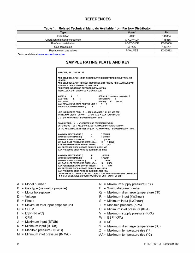
SAMPLE RATING PLATE AND KEY
A = Model numberB = Gas type (natural or propane)C = Motor horsepowerD = VoltageE = PhaseF = Maximum total input amps for unitG = SCFMH = ESP (IN WC)I = CFMJ = Maximum input (BTUh)K = Minimum input (BTUh)L = Manifold pressure (IN WC)M = Minimum inlet pressure (IN WC)
N = Maximum supply pressure (PSI)P = Wiring diagram numberQ = Maximum discharge temperature (°F)R = Maximum input (kW/hour)S = Minimum input (kW/hour)T = Manifold pressure (KPA)U = Minimum inlet pressure (KPA)V = Maximum supply pressure (KPA)W = ESP (KPA)X = M3
Y = Maximum discharge temperature (°C)Z = Maximum temperature rise (°F)AA = Maximum temperature rise (°C)
Table 1. Related Technical Manuals Available from Factory DistributorType Form* PN
Installation I-RDF 148384Operation/maintenance/service O-ADF/RDF 148385
Roof curb installation I-OPT-C-DE D303068Gas conversion CP-GC 143147
Replacement gas valves P-VALVES D300522
*Also available at www.reznorhvac.com.
MERCER, PA. USA 16137
ANSI Z83.4/CSA 3.7-2013 NON-RECIRCULATING DIRECT-FIRED INDUSTRIAL AIR HEATERANSI Z83.4/CSA 3.7-2013 DIRECT INDUSTRIEL ONT TIRE DU RÉCHAUFFEUR D'AIRFOR INDUSTRIAL/COMMERCIAL USE ONLYFOR EITHER INDOOR OR OUTDOOR INSTALLATIONINSTALLER À L'INTÉRIEUR OU À L'EXTÉRIEUR
MODEL { A } SERIAL # { computer generated }GAS TYPE{ B } MOTOR HP{ C }VOLTAGE { D } PHASE{ E } 60 HZMAX TOTAL INPUT AMPS FOR THE UNIT { F }WIRING DIAGRAM NUMBER: { P }
UNIT IS EQUIPPED FOR { G } SCFM AGAINST { H } IN WC ESPWITH A MAX DISCH TEMP OF { Q } °F AND A MAX TEMP RISE OF{ Z } °F AND CANNOT BE USED BELOW -40 °F
CONCU POUR { X } M3 CONTRE UNE PRESSION STATIQUEXTERNE DE { W } KPA (PO C.E.) WITH A MAX DISCHARGE TEMP OF{ Y } °C AND A MAX TEMP RISE OF { AA } °C AND CANNOT BE USED BELOW -40 °C.
MAXIMUM INPUT RATING { J } BTU/HRMINIMUM INPUT RATING ( K } BTU/HRNORMAL MANIFOLD PRESS { L } IN WCMIN GAS INLET PRESS. FOR BURN. ADJ. { M } IN WCMAX PERMISSIBLE GAS SUPPLY PRESS. { N } PSIMIN PRESSURE DROP ACROSS BURNER 0.25 IN WCMAX PRESSURE DROP ACROSS BURNER 0.75 IN WC
MAXIMUM INPUT RATING { R } KW/HRMINIMUM INPUT RATING { S } KW/HRNORMAL MANIFOLD PRESS. { T } KPAMIN GAS INLET PRESS. FOR BURN. ADJ. { U } KPAMAX PERMISSIBLE GAS SUPPLY PRESS. { V } KPAMIN PRESSURE DROP ACROSS BURNER 0.0625 KPAMAX PRESSURE DROP ACROSS BURNER 0.1875 KPACLEARANCES TO COMBUSTIBLES: TOP, BOTTOM, AND SIDE OPPOSITE CONTROLS - 1 INCH. FOR SERVICE ON CONTROL SIDE OF UNIT - WIDTH OF UNIT

3P-RDF (10-19) PN270069R12
SERIAL NUMBERS
Serial number format changed in June of 2015. Use the following information to decode system serial numbers:
Decoding a System Serial Number for ALL Models Before JUN 2015 Serial No. Sample: BLJ 82 V1 N 00000 CA MV7 Elements of No.: 1 | 2 | 3 | 4 | 5 | 6 | 7 Key: 1 = Date of manufacture (refer to Table 2) 2 = Type of pilot system (refer to P-VALVES manual listed in Table 1) 3 = Type of gas valve (refer to P-VALVES manual listed in Table 1) 4 = Type of gas (N = natural, L = propane) 5 = Consecutive number (identification only) 6 = Type of air control (CA = constant air volume, VA = variable air volume, RA = recirculation air) 7 = Type of Maxitrol gas control (MV7 = Maxitrol System 14, MV8 = Maxitrol System 14A, MVC = Maxitrol A200) Decoding a System Serial Number for ALL Models After MAY 2015 Serial No. Sample: BOG 3060 000000 Elements Key No.: 1 | 2 | 3 Key: 1 = Date of manufacture (refer to Table 2) 2 = Plant of manufacture (3060 = Mercer, 3062 = Monterrey) 3 = Consecutive number
Table 2. Serial Number Date Codes (Month and Year)
YearMonth
JAN FEB MAR APR MAY JUN JUL AUG SEP OCT NOV DEC2003 BCA BCB BCC BCD BCE BCF BCG BCH BCI BCJ BCK BCL2004 BDA BDB` BDC BDD BDE BDF BDG BDH BDI BDJ BDK BDL2005 BEA BEB BEC BED BEE BEF BEG BEH BEI BEJ BEK BEL2006 BFA BFB BFC BFD BFE BFF BFG BFH BFI BFJ BFK BFL2007 BGA BGB BGC BGD BGE BGF BGG BGH BGI BGJ BGK BGL2008 BHA BHB BHC BHD BHE BHF BHG BHH BHI BHJ BHK BHL2009 BIA BIB BIC BID BIE BIF BIG BIH BII BIJ BIK BIL2010 BJA BJB BJC BJD BJE BJF BJG BJH BJI BJJ BJK BJL2011 BKA BKB BKC BKD BKE BKF BKG BKH BKI BKJ BKK BKL2012 BLA BLB BLC BLD BLE BLF BLG BLH BLI BLJ BLK BLL2013 BMA BMB BMC BMD BME BMF BMG BMH BMI BMJ BMK BML2014 BNA BNB BNC BND BNE BNF BNG BNH BNI BNJ BNK BNL2015 BOA BOB BOC BOD BOE BOF BOG BOH BOI BOJ BOK BOL2016 BPA BPB BPC BPD BPE BPF BPG BPH BPI BPJ BPK BPL2017 BQA BQB BQC BQD BQE BQF BQG BQH BQI BQJ BQK BQL2018 BRA BRB BRC BRD BRE BRF BRG BRH BRI BRJ BRK BRL2019 BSA BSB BSC BSD BSE BSF BSG BSH BSI BSJ BSK BSL2020 BTA BTB BTC BTD BTE BTF BTG BTH BTI BTJ BTK BTL2021 BUA BUB BUC BUD BUE BUF BUG BUH BUI BUJ BUK BUL2022 BVA BVB BVC BVD BVE BVF BVG BVH BVI BVJ BVK BVL2023 BWA BWB BWC BWD BWE BWF BWG BWH BWI BWJ BWK BWL2024 BXA BXB BXC BXD BXE BXF BXG BXH BXI BXJ BXK BXL2025 BYA BYB BYC BYD BYE BYF BYG BYH BYI BYJ BYK BYL

4 P-RDF (10-19) PN270069R12
ELECTRICAL COMPONENTS
NOTE:
• Figure 1 shows the approximate locations of controls on model RDF series 3 units. Manufacture of series 3 units began in SEP 2003. Model RDF units manufactured prior to series 3 have similar controls but the control locations are different. Because this product has experienced ongoing development, always provide the complete model and serial number when inquiring about or ordering replacement parts.
• Table 3, Table 4, Table 5, Table 6, and Table 7 list electrical components. Figure 2 and Figure 3 show individual electrical components.
Figure 1. Electrical Control Compartment Typical Component Locations
Control Relays
Ignitor Module
Dirty Filter Switch
High and Low Pressure Switches
Contactor or Starter
Circuit Analyzer
Transformer
Amplifier or Signal Conditioner

5P-RDF (10-19) PN270069R12
Table 3. Electrical ComponentsItem No. Component Description PN Location
1
Relay SPST or SPDT, 24V coil (units manufactured after AUG 2011) 211411
Control compartment
Socket base Relay 211415Relay replacement kit
Replaces PNs 14747, 18549, 98118, and 103317 (units manufactured before SEP 2011) 263527
Relay SPST or SPDT, 120V coil (units manufactured after AUG 2011) 211414Socket base Relay 211415Relay replacement kit Replaces PNs 103318 and 103319 (units manufactured before SEP 2011) 263530
2Time delay relay
Low fire, 24V coil, Thermodisc #F12S20, style 305139 (units manufactured before MAR 1996) 89254
3 For freezestat bypass, T&B Agastst #VTM1ULA 896614 Prepurge, 24V coil, Thermodisc #12S20 528875 Relay 24V coil, Essex #91-102006-1300 1106566
Limit switchManual reset, Thermodisc 330545, L150 82610 Blower
discharge7 Automatic reset, Thermodisc #60T11-312616, L135 86979
8 Limit control/freezestat High ambient/outside air cutoff, adjustable, J/C #A19AAF-12C (replaces PN 16108) 126170
Control compartment8A
ClampGrommet 131993
8B Cable 132065
9 Flame safety limit ECO, opens at 306°F, Thermodisc #G4AP0200152C 82414 Gas train compartment
10 Firestat Honeywell #L4029E1029, 200°F 42782 Blower discharge
11 Spark generator 120V, Honeywell #Q624A1014 (units manufactured before MAR 1996) 86974
Control compartment
12 Pressure switch Low air pressure, 0.25 IN WC setting (units manufactured after DEC 2002) 20393212A Pressure switch kit Low air pressure, terminals, 0.20-inch switch (units manufactured before JAN 2003) 19380613 Pressure switch High air pressure, 0.75 IN WC setting (units manufactured after DEC 2002) 203933
13A Pressure switch kit High air pressure, terminals, 0.90-inch switch (units manufactured before JAN 2003) 19380714 Pressure switch Air pressure, 0.65 IN WC setting (option AR19, AR20, AR22, or AR23) 207177
14A Pressure switch kit Air pressure, wires, terminals, 0.65-inch switch (option AR19, AR20, AR22, or AR23) (replaces PN 87250) 193809
15 Pressure switch Air pressure, 0.50 IN WC setting (option AR19, AR20, AR22, or AR23) 207179
15A Pressure switch kit Air pressure, wires, terminals, 0.50 IN WC switch (option AR19, AR20, AR22, or AR23) (replaces PN 87249) 193808
16 Tee Plastic, for air pressure tubing, 3/16 × 1/16 ID 87482
17 Tubing (not shown)
Plastic, yellow, for air pressure switch, 3/16 OD × 14 inches 122855Plastic, clear, for air pressure switch, 3/16 OD × 3 feet 102401
18 Bushing and screen Insect screen, for sensing probes (not shown) 96794 —
19 Contactor HCC-2XQ01AA, 24V (used with option BM80 or BM81 manifold) 203935
Control compartment
20 Analyzer board Diagnostic circuit (standard beginning with series 3, option BS2 prior to series 3) 151263
20A Replacement bulbFor circuit analyzer board, series 3 125189For circuit analyzer board (option BS2 before series 3) 101889
20B Replacement relay For circuit analyzer board, SKMP-2C-24AC 151271
21 Terminal block* #KT3 144972
21A Adapter Terminal block 14497322 Outlet receptacle Convenience, Hubbell #GF5362 (separate electrical supply) 9691223 Pressure switch Dirty filter, Tri-Delta #AP4434, set at 0.3 IN WC 105507
23A Tubing (not shown) Plastic, clear, for dirty filter pressure switch, 3/16 OD × 112 inches 179302
24 Fuse Refer to Table 4Control
compartment24A Fuseholder Buss model HTB-481 (units manufactured after JUL 2012) 6024125 Transformer Refer to Table 5
26 System switch DPDT, Winter/Off/Summer, Cutler Hammer 7561K6 101900 Space (console)
27 Service switch SPDT, Cutler Hammer 7505K6 101901 Control compartment
28 Null pressure switch 0.01–0.20 IN WC, Dwyer #1640-0 (options AR20 and AR23) 88052 Heated
space
29 Potentiometer* Honeywell 112894FA (options AR19 and AR22) 16110 Space
*Also located on remote console.

6 P-RDF (10-19) PN270069R12
Table 3. Electrical ComponentsItem No. Component Description PN Location
30 Pressure sensor Photohelic, 3000-00-N24VAC (options AR36 and AR37) 158893
Remote30A Sampling tube For pressure sensor (not shown) 15971431 Remote console Refer to Table 632 Disconnect switch Refer to Table 7
—Continued
ELECTRICAL COMPONENTS—CONTINUED
Table 4. Fuses (Item 24)Description PN
2.5A, #3210 (spark ignition) 61542Bussman FRN-R15, 230/1 14667Bussman FRN-R30, 208/230/3 31892Bussman FRN-R10, 208/3 89265Bussman FRN-R7, 230/3 16207Bussman FRN-R25, 208/3 45054Bussman FRN-R60 31895Bussman FRN-R50 87957Bussman FRN-R90 89931Bussman FRN-R150 91077Bussman FRN-R175 91595Bussman FRS-R3.5, 460/3 89266Bussman FRS-R8, 460/3 89268Bussman FRS-R5, 460/3 89267Bussman FRS-R15, 460/3 87638Bussman FRS25 31891Bussman FRS-R40 899368A, Fusetron 3AG-8 (hot surface ignition) 386365A, Fusetron MDL 3AG 90335
Table 5. Transformers (Item 25)Volts Out
Volts In VA Description PN
24
12040 Basler #BE141650-WAA (used with spark ignition, two (2) required to replace PN 61806) 103055500 Hevi-Duty T500E 159842
120/240 250 TB1-81146 (used with hot surface ignition) 38634208 200 Hevi-Duty #2223034T00 39094
208/230/460 500 Hevi-Duty T500CK 159843208/240 40 Basler #BE21539001 (two (2) required to replace PN 61807) 103497
208/240/480/575 200 C0200KAT or Hevi-Duty #2123105t00 39095460 40 Basler #BE23975001 (two (2) required to replace PN 61808) 103498
110208 500 Hevi-Duty #2227003T00 86998
208/230/460/575 275 C0275KAU E5E 105202230/460 500 Hevi-Duty #2227001T00 86997
120 208/240/480/575 275 Eaton #C0275KAU 105202

7P-RDF (10-19) PN270069R12
Table 6. Remote Console (Item 31) Technical Data and ComponentsAvailable Features Control Box Assembly Dimensions
Indicator Lights Temperature Sensor/Selector? Potentiometer?
Length Height* DepthInches
Blower On, Burner On, Safety Lockout
Yes No10-13/16
7-3/8 2-5/8
No YesNo NoYes Yes 15-13/16
Blower On, Burner On, Safety Lockout, Dirty
Filter Indicator
Yes Yes
15-13/16Yes NoNo YesNo No
Item No. Component Description PN
31A BoxRemote console, 10-9/16 × 7-1/4 × 2-5/8 inches 107010Remote console, 15-9/16 × 7-1/4 × 2-5/8 inches 107011
31B Mounting ringFor 10-13/16-inch-long box 107014For 15-13/16-inch-long box 107015
31C Indicator light Red lens, Solico 5TD1L-R-B5 10188931CC Bushing For installing indicator light on old-style console 10674731D Control switch DPDT, Cutler Hammer #7561K6 10190031E Potentiometer Honeywell 112894FA 16110
31F Temperature selector
Options AG30 and AG3186988101165
Option AG32 87101Option AG33 86990Option AG47 204455Options AG48 and AG51 204451
*Changed OCT 2001.
NOTE:
• Remote console features depend on the option selected.
• All available options provide a control switch.
• The temperature sensor/selector is available with gas control options AG30, AG31, AG32, AG33, AG47, AG48, and AG51.
• The potentiometer is available with air control options AR19 and AR22.
• Refer to the custom wiring diagram for control wiring.
• If the remote console is to be recess-mounted, subtract 7/8 inch from the length and height listed in Table 6 when mounting.

8 P-RDF (10-19) PN270069R12
ELECTRICAL COMPONENTS—CONTINUED
Table 7. Disconnect Switches (Item 32)
Application Amps Voltage
Installation LocationUS Canada
Non-Fusible Fusible Non-Fusible FusiblePN (Option)
Indoor
30240 40267 (CP1) 40268 (CP2) —600 50365 (CP3) 50366 (CP4) 208053 (CP58) 208045 (CP41)
60240 161462 (CP21) 89932* (CP17) —
600 161464 (CP23) 90974* (CP20) 208055 (CP60) 208047 (CP43)
100240 161463 (CP22) 90973* (CP18) —
600 164330 (CP24) 155010* (CP36) 208057 (CP62) 208049 (CP45)
200240 155005 (CP26) 91076* (CP19) —
600 155009 (CP35) 155011* (CP37) 208059 (CP64) 208051 (CP47)
Outdoor (raintight)
30240 40269 (CP5) 87147 (CP6) —600 50367 (CP7) 50368 (CP8) 208054 (CP59) 208046 (CP42)
60240 161469 (CP30) 89932 (CP17) —600 155012 (CP38) 90974 (CP20) 208056 (CP61) 208048 (CP44)
100240 162834 (CP31) 90973 (CP18) —600 155013 (CP39) 155010 (CP36) 208058 (CP63) 208050 (CP46)
200240 155007 (CP32) 91076 (CP19) —600 155014 (CP40) 155011 (CP37) 208060 (CP65) 208052 (CP48)
Application
Motor**
Amps
Installation Location
Voltage/Phase HorsepowerUS Canada
Non-Fusible Fusible Non-Fusible FusibleOption
Indoor
115/11/4 to 1-1/2 30 CP1 CP2 CP60 CP43
2 to 3 60 CP21 CP27 CP60 CP43
208/1 and 230/11/4 to 3 30 CP1 CP2 CP58 CP415 to 10 60 CP21 CP27 CP60 CP43
208/3 and 230/3
1/4 to 5 30 CP1 CP2 CP58 CP417-1/2 to 15 60 CP21 CP27 CP60 CP43
20 to 25 100 CP22 CP28 CP62 CP4530 200 CP26 CP29 CP64 CP47
460/3 and 575/31/4 to 15 30 CP3 CP4 CP58 CP4120 to 30 60 CP23 CP33 CP60 CP43
Outdoor (raintight)
115/11/4 to 1-1/2 30 CP5 CP6 CP59 CP42
2 to 3 60 CP30 CP17 CP61 CP44
208/1 and 230/11/4 to 3 30 CP5 CP6 CP59 CP425 to 10 60 CP30 CP17 CP61 CP44
208/3 and 230/3
1/4 to 5 30 CP5 CP6 CP59 CP427-1/2 to 15 60 CP30 CP17 CP61 CP44
20 to 25 100 CP31 CP18 CP63 CP4630 200 CP32 CP19 CP65 CP48
460/3 and 575/31/4 to 15 30 CP7 CP8 CP59 CP4220 to 30 60 CP38 CP20 CP61 CP44
*Application uses an outdoor switch.
**Motor voltage varies in accordance with model and unit size.
9P-RDF (10-19) PN270069R12
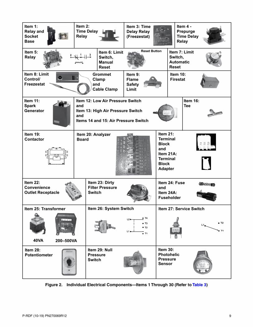
Figure 2. Individual Electrical Components—Items 1 Through 30 (Refer to Table 3)
Item 3: Time Delay Relay (Freezestat)
Item 4 - Prepurge Time Delay Relay
Item 5: Relay
Item 2: Time Delay Relay
Item 8: Limit Control/ Freezestat
Item 6: Limit Switch, Manual Reset
Reset Button Item 7: Limit Switch, Automatic Reset
Grommet Clamp and Cable Clamp
Item 11: Spark Generator
Item 10: Firestat
Item 1: Relay and Socket Base
Item 9: Flame Safety Limit
Item 24: Fuse and Item 24A: Fuseholder
Item 20: Analyzer Board
Item 25: Transformer
40VA
Item 19: Contactor
Item 26: System Switch Item 27: Service Switch
Item 28: Potentiometer
200–500VA
Item 29: Null Pressure Switch
Item 30: Photohelic Pressure Sensor
Item 12: Low Air Pressure Switch and Item 13: High Air Pressure Switch and Items 14 and 15: Air Pressure Switch
Item 16: Tee
Item 21: Terminal Block and Item 21A: Terminal Block Adapter
Item 22: Convenience Outlet Receptacle
Item 23: Dirty Filter Pressure Switch

10 P-RDF (10-19) PN270069R12
Figure 3. Individual Electrical Components—Items 31 and 32 (Refer to Table 3)
Item 31: Remote Console
31B
31E
Item 31A: Remote Console Box
31C 31CC
31D
Item 32: Disconnect Switch
ELECTRICAL COMPONENTS—CONTINUED

11P-RDF (10-19) PN270069R12
Figure 4. Motor Contactor and Starter Contactor/Overload
Overload
Motor Contactor (Option AN2)
Contactor
Starter Contactor/Overload (Option AN10)
BLOWER MOTOR, MOTOR CONTACTOR, AND STARTER CONTACTOR
Units Manufactured After AUG 2003
NOTE:
• The motor contactor and starter contactor/overload are shown in Figure 4.
• Replacement motors are listed by type and horsepower for open-type motors, TEFC-type (totally-enclosed fan-cooled) motors, and EE-type (premium-efficiency) motors. Highlighted motors in Table 8, Table 9, and Table 10 do not have internal overload protection and must be used with the motor starter and overload listed.
• For motors with internal overloads, the standard motor contactor (see Figure 4) is manufacturer’s model number HCC-3XQOICY (PN 216386, option AN2).
• Units with two-speed motors are equipped with IEC two-speed starter contactors (with 24V coils) and overloads (option AN10). When ordering a replacement IEC starter (refer to Table 11) or overload, check the manufacturer’s number on both parts. If the number is different than that listed in Table 8, Table 9, or Table 10, both components must be replaced.
• Motor contactors and starters (with overload) are located in the electrical compartment.
• Replacement coils for units with IEC starters are listed in Table 12.

12 P-RDF (10-19) PN270069R12
BLOWER MOTOR, MOTOR CONTACTOR, AND STARTER CONTACTOR—CONTINUED
Units Manufactured After AUG 2003—Continued
Table 8. Open-Type Blower Motors with Starters/Overloads (Units Manufactured After AUG 2003)
HP
Motor Starter (Option AN10)
MFR’s Model
Full Load Amps (FLA)
Shaft Size (IN)
Voltage/Phase
Frame Size SF* PF* EFF*
(%)PN
Starter Contactor Starter Overload
MFR’s Model PN GE
ModelMin
AmpsMax
Amps PN
1/2
AO-BF2054 8.8 5/8 120/1 56Z 1.2 — 102627 CL00A310T-1 151275 RTA1-N 8.0 12.0 151193AO-BF2054 5.1 5/8 208/1 56Z 1.2 — 102627 CL00A310T-1 151275 RTA1-L 4.0 6.3 151191AO-BF2054 4.4 5/8 240/1 56Z 1.2 — 102627 CL00A310T-1 151275 RTA1-L 4.0 6.3 151191
AO-H880 2.5 5/8 208/3 LA56 1.3 — 159183 CL00A310T-1 151275 RTA1-J 1.8 2.7 151189AO-H880 3.0 5/8 240/3 LA56 1.3 — 159183 CL00A310T-1 151275 RTA1-K 2.5 4.1 151190AO-H880 1.5 5/8 480/3 LA56 1.3 — 159183 CL00A310T-1 151275 RTA1-H 1.3 1.9 151188
AOS-H991 0.9 5/8 575/3 H56 1.3 — 202089 CL00A310T-1 151275 RTA1-F 0.7 1.1 151186
3/4
AO-312P629 11.0 5/8 120/1 B56 1.3 — 93548 CL01A310T-1 151276 RTA1-P 10.0 16.0 151194AO-312P629 6.3 5/8 208/1 B56 1.3 — 93548 CL00A310T-1 151275 RTA1-M 5.5 8.5 151192AO-312P629 5.5 5/8 240/1 B56 1.3 — 93548 CL00A310T-1 151275 RTA1-L 4.0 6.3 151191AO-312P696 2.9 5/8 208/3 D56 1.3 — 36951 CL00A310T-1 151275 RTA1-K 2.5 4.1 151190AO-312P696 2.6 5/8 240/3 D56 1.3 — 36951 CL00A310T-1 151275 RTA1-K 2.5 4.1 151190AO-312P696 1.3 5/8 480/3 D56 1.3 — 36951 CL00A310T-1 151275 RTA1-G 1.0 1.5 151187AOS - H992 1.0 5/8 575/3 H56 1.3 — 202090 CL00A310T-1 151275 RTA1-F 0.7 1.1 151186
1
AO-C523 13.0 5/8 120/1 H56 1.3 — 13685 CL01A310T-1 151276 RTA1-P 10.0 16.0 151194AO-C523 7.5 5/8 208/1 H56 1.3 — 13685 CL00A310T-1 151275 RTA1-M 5.5 8.5 151192AO-C523 6.5 5/8 240/1 H56 1.3 — 13685 CL00A310T-1 151275 RTA1-M 5.5 8.5 151192AO-H882 3.7 5/8 208/3 F56 1.2 — 79 36580 CL00A310T-1 151275 RTA1-K 2.5 4.1 151190AO-H882 3.2 5/8 240/3 F56 1.2 — 79 36580 CL00A310T-1 151275 RTA1-K 2.5 4.1 151190AO-H882 1.6 5/8 480/3 F56 1.2 — 79 36580 CL00A310T-1 151275 RTA1-H 1.3 1.9 151188AO-E1006 1.1 7/8 575/3 N143T 1.2 — 82.5 158175 CL00A310T-1 151275 RTA1-G 1.0 1.5 151187
1.5
AO-C621 15.0 5/8 120/1 56 1.2 86.4 77.2 194202 CL01A310T-1 151276 RTA1-P 10.0 16.0 151194AO-C621 7.8 5/8 208/1 56 1.2 86.4 77.2 194202 CL00A310T-1 151275 RTA1-M 5.5 8.5 151192AO-C621 7.5 5/8 240/1 56 1.2 86.4 77.2 194202 CL00A310T-1 151275 RTA1-M 5.5 8.5 151192AO-H884 5.6 5/8 208/3 UA56 1.2 66.4 78.6 115859 CL00A310T-1 151275 RTA1-L 4.0 6.3 151191AO-H884 5.0 5/8 240/3 UA56 1.2 66.4 78.6 115859 CL00A310T-1 151275 RTA1-L 4.0 6.3 151191AO-H884 2.8 5/8 480/3 UA56 1.2 66.4 78.6 115859 CL00A310T-1 151275 RTA1-K 2.5 4.1 151190AO-E1007 1.6 7/8 575/3 R145T 1.2 85.3 84.0 158162 CL00A310T-1 151275 RTA1-H 1.3 1.9 151188
2
AO-RB1204A 24.6 5/8 120/1 56H — 202581 CL04A310M-1 151279 RTA1-U 21.0 26.0 151198AO-RB1204A 12.3 5/8 208/1 56H — 202581 CL01A310T-1 151276 RTA1-P 10.0 16.0 151194AO-RB1204A 12.3 5/8 240/1 56H — 202581 CL01A310T-1 151276 RTA1-P 10.0 16.0 151194
AO-H886 7.0 7/8 208/3 56HZ 1.2 67 79 159327 CL00A310T-1 151275 RTA1-M 5.5 8.5 151192AO-H886 6.6 7/8 240/3 56HZ 1.2 67 79 159327 CL00A310T-1 151275 RTA1-M 5.5 8.5 151192AO-H886 3.5 7/8 480/3 56HZ 1.2 67 79 159327 CL00A310T-1 151275 RTA1-K 2.5 4.1 151190AO-E1008 2.1 7/8 575/3 P145T 1.2 86 84.0 158176 CL00A310T-1 151275 RTA1-J 1.8 2.7 151189
3
AO-B735 13.7 5/8 208/1 L56 1.2 — 111560 CL01A310T-1 151276 RTA1-P 10.0 16.0 151194AO-B735 12.4 5/8 230/1 L56 1.2 — 111560 CL01A310T-1 151276 RTA1-P 10.0 16.0 151194AO-H845 9.0 7/8 208/3 P56HZ 1.2 — 159185 CL00A310T-1 151275 RTA1-N 8.0 12.0 151193AO-H845 8.6 7/8 240/3 P56HZ 1.2 — 159185 CL00A310T-1 151275 RTA1-N 8.0 12.0 151193AO-H845 4.3 7/8 480/3 P56HZ 1.2 — 159185 CL00A310T-1 151275 RTA1-L 4.0 6.3 151191AO-H954 3.6 7/8 575/3 N56HZ 1.2 80.3 83.8 120019 CL00A310T-1 151275 RTA1-K 2.5 4.1 151190
5
AO-V211 28.3 1-1/8 208/1 L184T — 111562 CL04A310M-1 151279 RTA1-V 25.0 32.0 151199AO-V211 25.6 1-1/8 240/1 L184T — 111562 CL04A310M-1 151279 RTA1-V 25.0 32.0 151199
AO-196033 13.4 7/8 208/3 Y56HZ 1.2 87.2 85 113371 CL01A310T-1 151276 RTA1-P 10.0 16.0 151194AO-196033 13.2 7/8 240/3 Y56HZ 1.2 87.2 85 113371 CL01A310T-1 151276 RTA1-P 10.0 16.0 151194AO-196033 6.6 7/8 480/3 Y56HZ 1.2 87.2 85 113371 CL00A310T-1 151275 RTA1-M 5.5 8.5 151192AO-H956 5.4 7/8 575/3 Y56HZ 1.2 85.9 85.3 120020 CL00A310T-1 151275 RTA1-L 4.0 6.3 151191
*SF = service factor, PF = power factor, and EFF = efficiency.

13P-RDF (10-19) PN270069R12
Table 8. Open-Type Blower Motors with Starters/Overloads (Units Manufactured After AUG 2003)
HP
Motor Starter (Option AN10)
MFR’s Model
Full Load Amps (FLA)
Shaft Size (IN)
Voltage/Phase
Frame Size SF* PF* EFF*
(%)PN
Starter Contactor Starter Overload
MFR’s Model PN GE
ModelMin
AmpsMax
Amps PN
7.5
AO-V305 35.4 1-3/8 208/1 S215T — 105828 CL06A311M-1 203687 RTA2-E 30.0 43.0 151206AO-V305 32.0 1-3/8 230/1 S215T — 105828 CL06A311M-1 203687 RTA2-E 30.0 43.0 151206AO-E300 22.5 1-3/8 208/3 213T — 105855 CL04A310M-1 151279 RTA1-U 21.0 26.0 151198AO-E300 19.4 1-3/8 240/3 213T — 105855 CL25A310T-1 1024071 RTA1-T 17.5 22.0 1024078AO-E300 9.7 1-3/8 480/3 213T — 105855 CL00A310T-1 151275 RTA1-N 8.0 12.0 151193AO-E324 7.8 1-3/8 575/3 S213T — 158164 CL00A310T-1 151275 RTA1-M 5.5 8.5 151192
10
AO-V303 42.0 1-3/8 208/1 S215T — 105830 CL06A311M-1 203687 RTA2-E 30.0 43.0 151206AO-V303 38.0 1-3/8 230/1 S215T — 105830 CL06A311M-1 203687 RTA2-E 30.0 43.0 151206AO-E301 31.0 1-3/8 208/3 215T — 105858 CL04A310M-1 151279 RTA1-V 25.0 32.0 151199AO-E301 26.0 1-3/8 240/3 215T — 105858 CL04A310M-1 151279 RTA1-V 25.0 32.0 151199AO-E301 13.0 1-3/8 480/3 215T — 105858 CL01A310T-1 151276 RTA1-P 10.0 16.0 151194AO-E325 10.4 1-3/8 575/3 S215T — 158163 CL01A310T-1 151276 RTA1-P 10.0 16.0 151194
15
B-FM2513T-8-F2 43.1 1-5/8 208/3 254T — 142287 CL06A311M-1 203687 RTA2-G 42.0 55.0 151202BALD-FM2523T 39.0 1-5/8 240/3 254T — 142288 CL06A311M-1 203687 RTA2-E 30.0 43.0 151206BALD-FM2523T 19.5 1-5/8 480/3 254T — 142288 CL25A310T-1 1024071 RTA1-T 17.5 22.0 1024078
B-EFM2513T-5-F2 16.0 1-5/8 575/3 254T — 142289 CL02A310T-1 151277 RTA1-S 14.5 18.0 151196
20
B-FM2515T-8-F2 58.7 1-5/8 208/3 256T 1.2 80 88.5 142295 CL07A311M-1 203793 RTA2-H 54.0 65.0 151203BAL-FM2515T-F2 53.0 1-5/8 240/3 256T 1.2 81 88.5 142296 CL07A311M-1 203793 RTA2-G 42.0 55.0 151202BAL-FM2515T-F2 26.5 1-5/8 480/3 256T 1.2 81 88.5 142296 CL04A310M-1 151279 RTA1-V 25.0 32.0 151199B-FM2515T-5-F2 21.2 1-5/8 575/3 256T 1.2 80 88.5 142297 CL25A310T-1 1024071 RTA1-T 17.5 22.0 1024078
25
E545-F2 69.8 1-7/8 208/3 S284T 1.15 84.1 91.7 159021 CL09A311M-1 203794 RTA2-j 64.0 82.0 151204E546-F2 60.6 1-7/8 240/3 S284T 1.15 84.1 91.7 159022 CL07A311M-1 203793 RTA2-H 54.0 65.0 151203E546-F2 30.3 1-7/8 480/3 S284T 1.15 84.1 91.7 159022 CL04A310M-1 151279 RTA1-V 25.0 32.0 151199E594-F2 24.3 1-7/8 575/3 S284T 1.15 84.1 91.7 159023 CL04A310M-1 151279 RTA1-U 21.0 26.0 151198
30
E547-F2 78.0 1-7/8 208/3 S286T 1.15 81 92.4 159024 CL09A311M-1 203794 RT2-J 64.0 82.0 151204E548-F2 75.0 1-7/8 240/3 S286T 1.15 81 92.4 159025 CL09A311M-1 203794 RT2-J 64.0 82.0 151204E548-F2 37.5 1-7/8 480/3 S286T 1.15 81 92.4 159025 CL06A311M-1 203687 RTA2-E 30.0 43.0 151206E595-F2 30.0 1-7/8 575/3 S286T 1.15 81 92.4 159026 CL04A310M-1 151279 RTA1-V 25.0 32.0 151199
*SF = service factor, PF = power factor, and EFF = efficiency.
—Continued
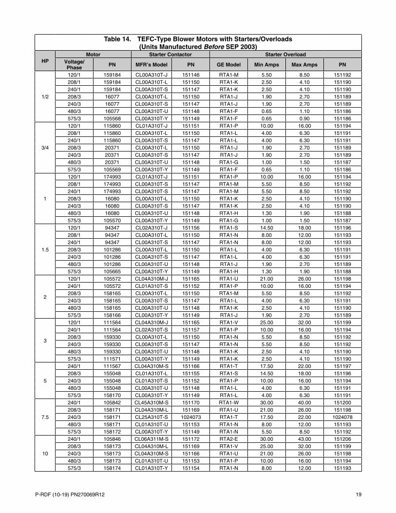
Table 9. TEFC-Type Blower Motors with Starters/Overloads (Units Manufactured After AUG 2003)
HP
Motor Starter (Option AN10)
MFR’s Model
Full Load Amps (FLA)
Shaft Size (IN)
Voltage/Phase
Frame Size SF* PF* EFF*
(%)PN
Starter Contactor Starter Overload
MFR’s Model PN GE
ModelMin
AmpsMax
Amps PN
1/2
AO-C613 7.2 5/8 120/1 J56 — 159184 CL00A310T-1 151275 RTA1-M 5.5 8.5 151192AO-C613 3.5 5/8 208/1 J56 — 159184 CL00A310T-1 151275 RTA1-K 2.5 4.1 151190AO-C613 3.6 5/8 240/1 J56 — 159184 CL00A310T-1 151275 RTA1-K 2.5 4.1 151190AO-H274 2.3 5/8 208/3 H56 1 59.5 74.8 16077 CL00A310T-1 151275 RTA1-J 1.8 2.7 151189AO-H274 2.0 5/8 240/3 H56 1 59.5 74.8 16077 CL00A310T-1 151275 RTA1-J 1.8 2.7 151189AO-H274 1.0 5/8 480/3 H56 1 59.5 74.8 16077 CL00A310T-1 151275 RTA1-F 0.7 1.1 151186AO-H276 0.7 5/8 575/3 J56 1.2 76.4 77 105568 CL00A310T-1 151275 RTA1-F 0.7 1.1 151186
3/4
AO-F353 11.0 5/8 120/1 F56 — 115860 CL01A310T-1 151276 RTA1-P 10.0 16.0 151194AO-F353 5.4 5/8 208/1 F56 — 115860 CL00A310T-1 151275 RTA1-L 4.0 6.3 151191AO-F353 5.5 5/8 240/1 F56 — 159184 CL00A310T-1 151275 RTA1-L 4.0 6.3 151191AO-H580 2.0 5/8 208/3 KA56 1 73.5 81.1 20371 CL00A310T-1 151275 RTA1-J 1.8 2.7 151189AO-H580 2.2 5/8 240/3 KA56 1 73.5 81.1 20371 CL00A310T-1 151275 RTA1-J 1.8 2.7 151189AO-H580 1.1 5/8 480/3 KA56 1 73.5 81.1 20371 CL00A310T-1 151275 RTA1-G 1.0 1.5 151187AO-H461 0.8 5/8 575/3 L56 1.2 78.3 82 105569 CL00A310T-1 151275 RTA1-F 0.7 1.1 151186
*SF = service factor, PF = power factor, and EFF = efficiency.
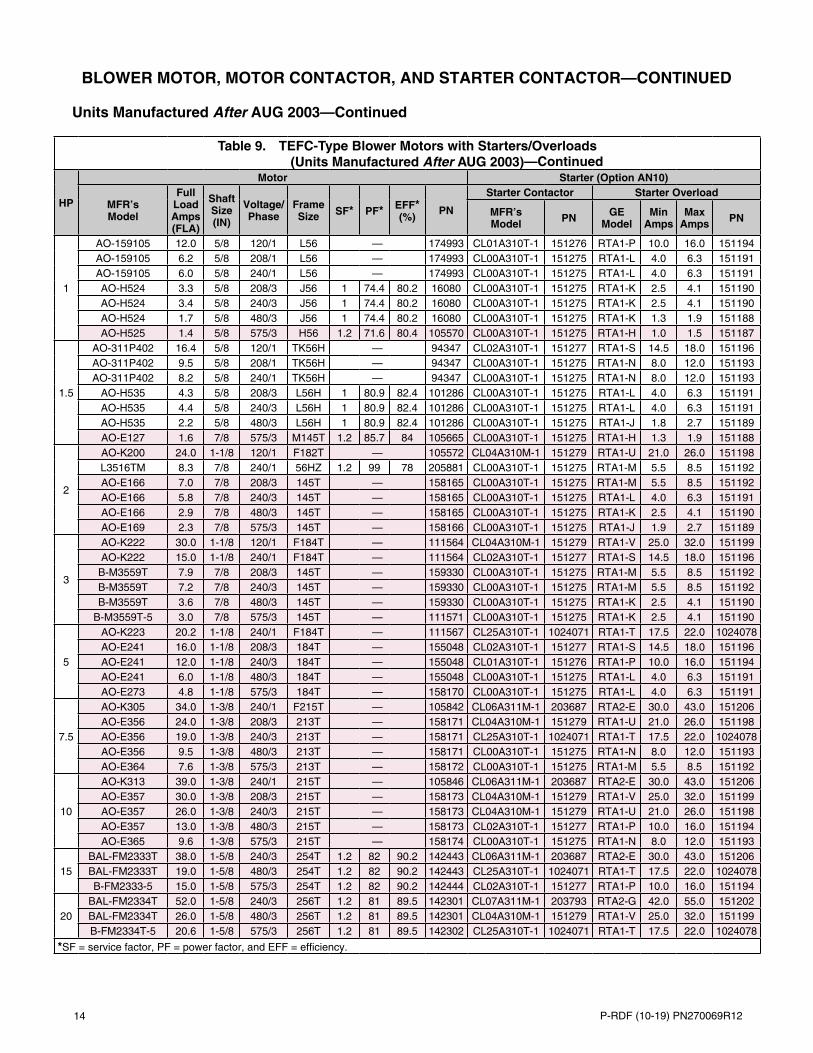
14 P-RDF (10-19) PN270069R12
Table 9. TEFC-Type Blower Motors with Starters/Overloads (Units Manufactured After AUG 2003)
HP
Motor Starter (Option AN10)
MFR’s Model
Full Load Amps (FLA)
Shaft Size (IN)
Voltage/Phase
Frame Size SF* PF* EFF*
(%)PN
Starter Contactor Starter Overload
MFR’s Model PN GE
ModelMin
AmpsMax
Amps PN
1
AO-159105 12.0 5/8 120/1 L56 — 174993 CL01A310T-1 151276 RTA1-P 10.0 16.0 151194AO-159105 6.2 5/8 208/1 L56 — 174993 CL00A310T-1 151275 RTA1-L 4.0 6.3 151191AO-159105 6.0 5/8 240/1 L56 — 174993 CL00A310T-1 151275 RTA1-L 4.0 6.3 151191AO-H524 3.3 5/8 208/3 J56 1 74.4 80.2 16080 CL00A310T-1 151275 RTA1-K 2.5 4.1 151190AO-H524 3.4 5/8 240/3 J56 1 74.4 80.2 16080 CL00A310T-1 151275 RTA1-K 2.5 4.1 151190AO-H524 1.7 5/8 480/3 J56 1 74.4 80.2 16080 CL00A310T-1 151275 RTA1-K 1.3 1.9 151188AO-H525 1.4 5/8 575/3 H56 1.2 71.6 80.4 105570 CL00A310T-1 151275 RTA1-H 1.0 1.5 151187
1.5
AO-311P402 16.4 5/8 120/1 TK56H — 94347 CL02A310T-1 151277 RTA1-S 14.5 18.0 151196AO-311P402 9.5 5/8 208/1 TK56H — 94347 CL00A310T-1 151275 RTA1-N 8.0 12.0 151193AO-311P402 8.2 5/8 240/1 TK56H — 94347 CL00A310T-1 151275 RTA1-N 8.0 12.0 151193
AO-H535 4.3 5/8 208/3 L56H 1 80.9 82.4 101286 CL00A310T-1 151275 RTA1-L 4.0 6.3 151191AO-H535 4.4 5/8 240/3 L56H 1 80.9 82.4 101286 CL00A310T-1 151275 RTA1-L 4.0 6.3 151191AO-H535 2.2 5/8 480/3 L56H 1 80.9 82.4 101286 CL00A310T-1 151275 RTA1-J 1.8 2.7 151189AO-E127 1.6 7/8 575/3 M145T 1.2 85.7 84 105665 CL00A310T-1 151275 RTA1-H 1.3 1.9 151188
2
AO-K200 24.0 1-1/8 120/1 F182T — 105572 CL04A310M-1 151279 RTA1-U 21.0 26.0 151198L3516TM 8.3 7/8 240/1 56HZ 1.2 99 78 205881 CL00A310T-1 151275 RTA1-M 5.5 8.5 151192AO-E166 7.0 7/8 208/3 145T — 158165 CL00A310T-1 151275 RTA1-M 5.5 8.5 151192AO-E166 5.8 7/8 240/3 145T — 158165 CL00A310T-1 151275 RTA1-L 4.0 6.3 151191AO-E166 2.9 7/8 480/3 145T — 158165 CL00A310T-1 151275 RTA1-K 2.5 4.1 151190AO-E169 2.3 7/8 575/3 145T — 158166 CL00A310T-1 151275 RTA1-J 1.9 2.7 151189
3
AO-K222 30.0 1-1/8 120/1 F184T — 111564 CL04A310M-1 151279 RTA1-V 25.0 32.0 151199AO-K222 15.0 1-1/8 240/1 F184T — 111564 CL02A310T-1 151277 RTA1-S 14.5 18.0 151196B-M3559T 7.9 7/8 208/3 145T — 159330 CL00A310T-1 151275 RTA1-M 5.5 8.5 151192B-M3559T 7.2 7/8 240/3 145T — 159330 CL00A310T-1 151275 RTA1-M 5.5 8.5 151192B-M3559T 3.6 7/8 480/3 145T — 159330 CL00A310T-1 151275 RTA1-K 2.5 4.1 151190
B-M3559T-5 3.0 7/8 575/3 145T — 111571 CL00A310T-1 151275 RTA1-K 2.5 4.1 151190
5
AO-K223 20.2 1-1/8 240/1 F184T — 111567 CL25A310T-1 1024071 RTA1-T 17.5 22.0 1024078AO-E241 16.0 1-1/8 208/3 184T — 155048 CL02A310T-1 151277 RTA1-S 14.5 18.0 151196AO-E241 12.0 1-1/8 240/3 184T — 155048 CL01A310T-1 151276 RTA1-P 10.0 16.0 151194AO-E241 6.0 1-1/8 480/3 184T — 155048 CL00A310T-1 151275 RTA1-L 4.0 6.3 151191AO-E273 4.8 1-1/8 575/3 184T — 158170 CL00A310T-1 151275 RTA1-L 4.0 6.3 151191
7.5
AO-K305 34.0 1-3/8 240/1 F215T — 105842 CL06A311M-1 203687 RTA2-E 30.0 43.0 151206AO-E356 24.0 1-3/8 208/3 213T — 158171 CL04A310M-1 151279 RTA1-U 21.0 26.0 151198AO-E356 19.0 1-3/8 240/3 213T — 158171 CL25A310T-1 1024071 RTA1-T 17.5 22.0 1024078AO-E356 9.5 1-3/8 480/3 213T — 158171 CL00A310T-1 151275 RTA1-N 8.0 12.0 151193AO-E364 7.6 1-3/8 575/3 213T — 158172 CL00A310T-1 151275 RTA1-M 5.5 8.5 151192
10
AO-K313 39.0 1-3/8 240/1 215T — 105846 CL06A311M-1 203687 RTA2-E 30.0 43.0 151206AO-E357 30.0 1-3/8 208/3 215T — 158173 CL04A310M-1 151279 RTA1-V 25.0 32.0 151199AO-E357 26.0 1-3/8 240/3 215T — 158173 CL04A310M-1 151279 RTA1-U 21.0 26.0 151198AO-E357 13.0 1-3/8 480/3 215T — 158173 CL02A310T-1 151277 RTA1-P 10.0 16.0 151194AO-E365 9.6 1-3/8 575/3 215T — 158174 CL00A310T-1 151275 RTA1-N 8.0 12.0 151193
15BAL-FM2333T 38.0 1-5/8 240/3 254T 1.2 82 90.2 142443 CL06A311M-1 203687 RTA2-E 30.0 43.0 151206BAL-FM2333T 19.0 1-5/8 480/3 254T 1.2 82 90.2 142443 CL25A310T-1 1024071 RTA1-T 17.5 22.0 1024078B-FM2333-5 15.0 1-5/8 575/3 254T 1.2 82 90.2 142444 CL02A310T-1 151277 RTA1-P 10.0 16.0 151194
20BAL-FM2334T 52.0 1-5/8 240/3 256T 1.2 81 89.5 142301 CL07A311M-1 203793 RTA2-G 42.0 55.0 151202BAL-FM2334T 26.0 1-5/8 480/3 256T 1.2 81 89.5 142301 CL04A310M-1 151279 RTA1-V 25.0 32.0 151199B-FM2334T-5 20.6 1-5/8 575/3 256T 1.2 81 89.5 142302 CL25A310T-1 1024071 RTA1-T 17.5 22.0 1024078
*SF = service factor, PF = power factor, and EFF = efficiency.
—Continued
BLOWER MOTOR, MOTOR CONTACTOR, AND STARTER CONTACTOR—CONTINUED
Units Manufactured After AUG 2003—Continued
P-RDF (10-19) PN270069R12 15
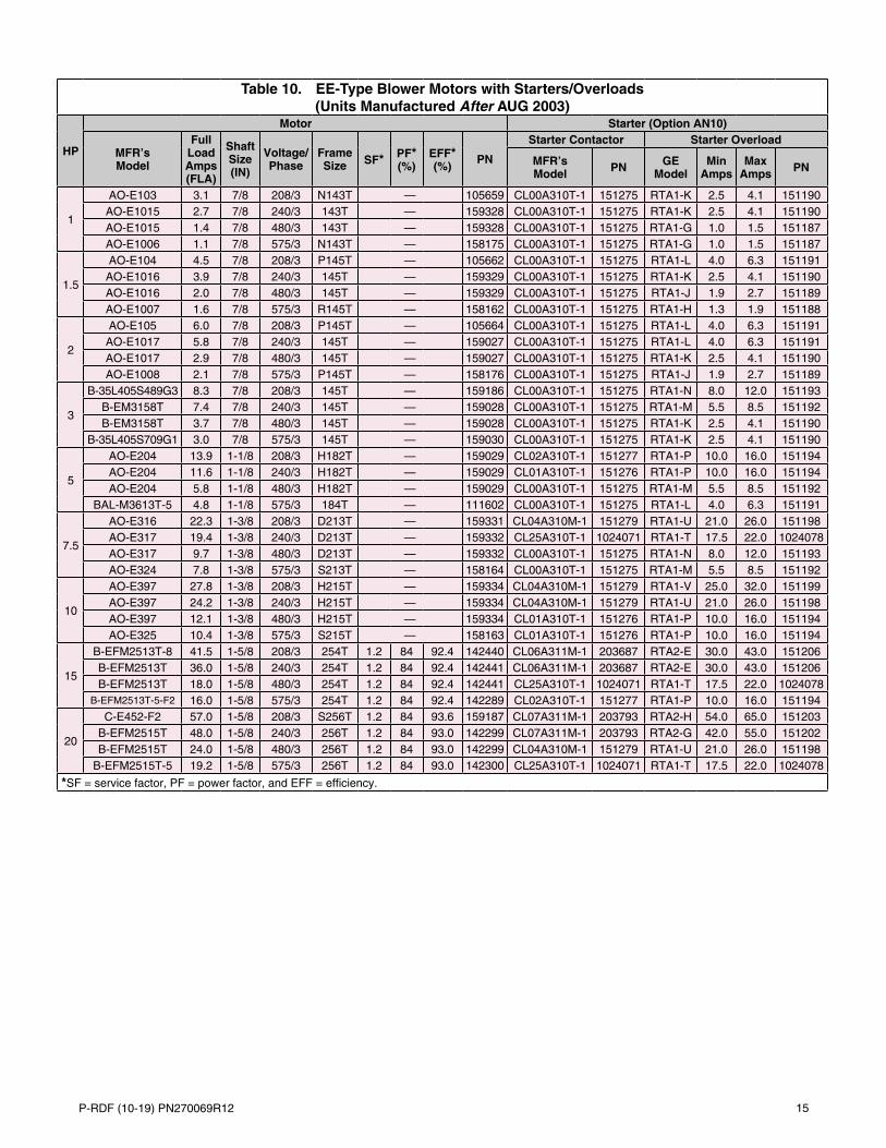
Table 10. EE-Type Blower Motors with Starters/Overloads (Units Manufactured After AUG 2003)
HP
Motor Starter (Option AN10)
MFR’s Model
Full Load Amps (FLA)
Shaft Size (IN)
Voltage/Phase
Frame Size SF* PF*
(%)EFF* (%)
PN
Starter Contactor Starter Overload
MFR’s Model PN GE
ModelMin
AmpsMax
Amps PN
1
AO-E103 3.1 7/8 208/3 N143T — 105659 CL00A310T-1 151275 RTA1-K 2.5 4.1 151190AO-E1015 2.7 7/8 240/3 143T — 159328 CL00A310T-1 151275 RTA1-K 2.5 4.1 151190AO-E1015 1.4 7/8 480/3 143T — 159328 CL00A310T-1 151275 RTA1-G 1.0 1.5 151187AO-E1006 1.1 7/8 575/3 N143T — 158175 CL00A310T-1 151275 RTA1-G 1.0 1.5 151187
1.5
AO-E104 4.5 7/8 208/3 P145T — 105662 CL00A310T-1 151275 RTA1-L 4.0 6.3 151191AO-E1016 3.9 7/8 240/3 145T — 159329 CL00A310T-1 151275 RTA1-K 2.5 4.1 151190AO-E1016 2.0 7/8 480/3 145T — 159329 CL00A310T-1 151275 RTA1-J 1.9 2.7 151189AO-E1007 1.6 7/8 575/3 R145T — 158162 CL00A310T-1 151275 RTA1-H 1.3 1.9 151188
2
AO-E105 6.0 7/8 208/3 P145T — 105664 CL00A310T-1 151275 RTA1-L 4.0 6.3 151191AO-E1017 5.8 7/8 240/3 145T — 159027 CL00A310T-1 151275 RTA1-L 4.0 6.3 151191AO-E1017 2.9 7/8 480/3 145T — 159027 CL00A310T-1 151275 RTA1-K 2.5 4.1 151190AO-E1008 2.1 7/8 575/3 P145T — 158176 CL00A310T-1 151275 RTA1-J 1.9 2.7 151189
3
B-35L405S489G3 8.3 7/8 208/3 145T — 159186 CL00A310T-1 151275 RTA1-N 8.0 12.0 151193B-EM3158T 7.4 7/8 240/3 145T — 159028 CL00A310T-1 151275 RTA1-M 5.5 8.5 151192B-EM3158T 3.7 7/8 480/3 145T — 159028 CL00A310T-1 151275 RTA1-K 2.5 4.1 151190
B-35L405S709G1 3.0 7/8 575/3 145T — 159030 CL00A310T-1 151275 RTA1-K 2.5 4.1 151190
5
AO-E204 13.9 1-1/8 208/3 H182T — 159029 CL02A310T-1 151277 RTA1-P 10.0 16.0 151194AO-E204 11.6 1-1/8 240/3 H182T — 159029 CL01A310T-1 151276 RTA1-P 10.0 16.0 151194AO-E204 5.8 1-1/8 480/3 H182T — 159029 CL00A310T-1 151275 RTA1-M 5.5 8.5 151192
BAL-M3613T-5 4.8 1-1/8 575/3 184T — 111602 CL00A310T-1 151275 RTA1-L 4.0 6.3 151191
7.5
AO-E316 22.3 1-3/8 208/3 D213T — 159331 CL04A310M-1 151279 RTA1-U 21.0 26.0 151198AO-E317 19.4 1-3/8 240/3 D213T — 159332 CL25A310T-1 1024071 RTA1-T 17.5 22.0 1024078AO-E317 9.7 1-3/8 480/3 D213T — 159332 CL00A310T-1 151275 RTA1-N 8.0 12.0 151193AO-E324 7.8 1-3/8 575/3 S213T — 158164 CL00A310T-1 151275 RTA1-M 5.5 8.5 151192
10
AO-E397 27.8 1-3/8 208/3 H215T — 159334 CL04A310M-1 151279 RTA1-V 25.0 32.0 151199AO-E397 24.2 1-3/8 240/3 H215T — 159334 CL04A310M-1 151279 RTA1-U 21.0 26.0 151198AO-E397 12.1 1-3/8 480/3 H215T — 159334 CL01A310T-1 151276 RTA1-P 10.0 16.0 151194AO-E325 10.4 1-3/8 575/3 S215T — 158163 CL01A310T-1 151276 RTA1-P 10.0 16.0 151194
15
B-EFM2513T-8 41.5 1-5/8 208/3 254T 1.2 84 92.4 142440 CL06A311M-1 203687 RTA2-E 30.0 43.0 151206B-EFM2513T 36.0 1-5/8 240/3 254T 1.2 84 92.4 142441 CL06A311M-1 203687 RTA2-E 30.0 43.0 151206B-EFM2513T 18.0 1-5/8 480/3 254T 1.2 84 92.4 142441 CL25A310T-1 1024071 RTA1-T 17.5 22.0 1024078
B-EFM2513T-5-F2 16.0 1-5/8 575/3 254T 1.2 84 92.4 142289 CL02A310T-1 151277 RTA1-P 10.0 16.0 151194
20
C-E452-F2 57.0 1-5/8 208/3 S256T 1.2 84 93.6 159187 CL07A311M-1 203793 RTA2-H 54.0 65.0 151203B-EFM2515T 48.0 1-5/8 240/3 256T 1.2 84 93.0 142299 CL07A311M-1 203793 RTA2-G 42.0 55.0 151202B-EFM2515T 24.0 1-5/8 480/3 256T 1.2 84 93.0 142299 CL04A310M-1 151279 RTA1-U 21.0 26.0 151198
B-EFM2515T-5 19.2 1-5/8 575/3 256T 1.2 84 93.0 142300 CL25A310T-1 1024071 RTA1-T 17.5 22.0 1024078
*SF = service factor, PF = power factor, and EFF = efficiency.
16 P-RDF (10-19) PN270069R12
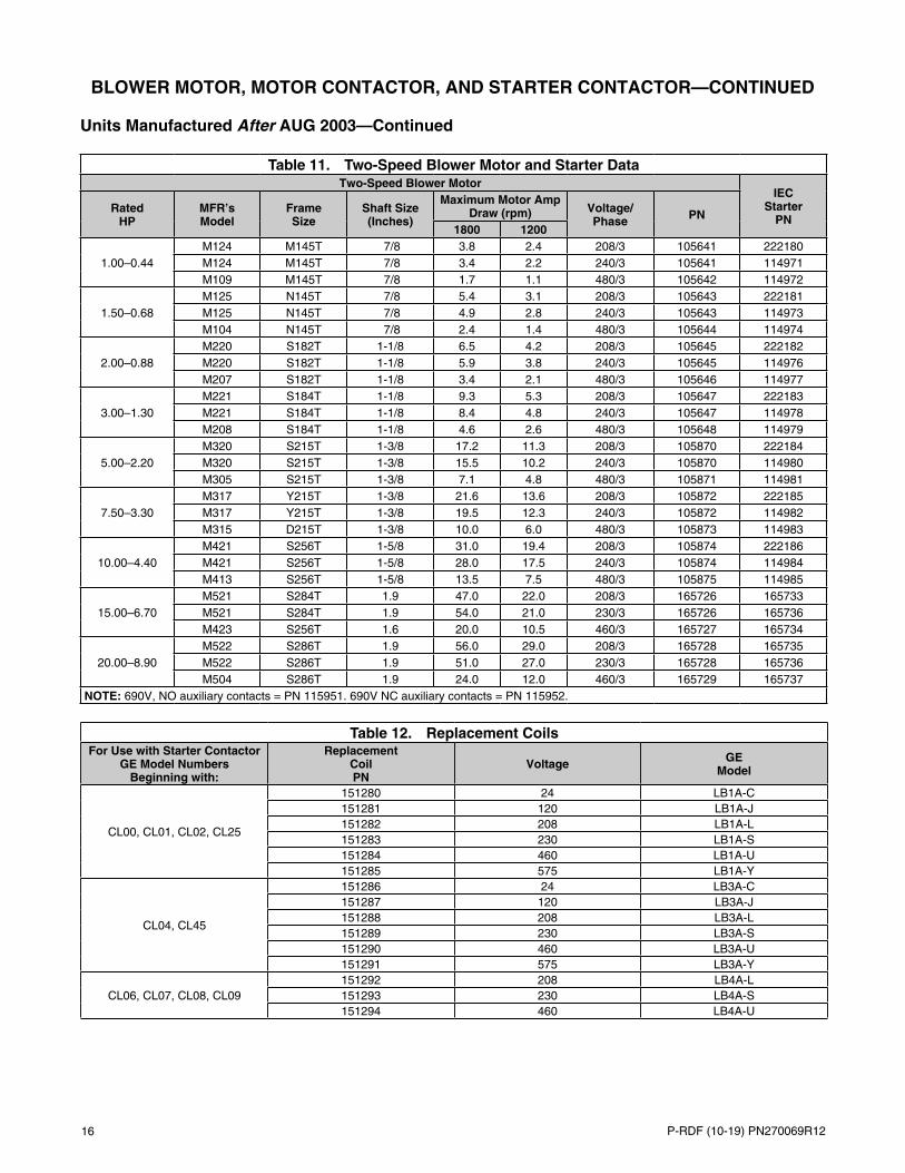
Table 11. Two-Speed Blower Motor and Starter DataTwo-Speed Blower Motor
IEC Starter
PNRated
HPMFR’s Model
Frame Size
Shaft Size (Inches)
Maximum Motor Amp Draw (rpm) Voltage/
Phase PN1800 1200
1.00–0.44M124 M145T 7/8 3.8 2.4 208/3 105641 222180M124 M145T 7/8 3.4 2.2 240/3 105641 114971M109 M145T 7/8 1.7 1.1 480/3 105642 114972
1.50–0.68M125 N145T 7/8 5.4 3.1 208/3 105643 222181M125 N145T 7/8 4.9 2.8 240/3 105643 114973M104 N145T 7/8 2.4 1.4 480/3 105644 114974
2.00–0.88M220 S182T 1-1/8 6.5 4.2 208/3 105645 222182M220 S182T 1-1/8 5.9 3.8 240/3 105645 114976M207 S182T 1-1/8 3.4 2.1 480/3 105646 114977
3.00–1.30M221 S184T 1-1/8 9.3 5.3 208/3 105647 222183M221 S184T 1-1/8 8.4 4.8 240/3 105647 114978M208 S184T 1-1/8 4.6 2.6 480/3 105648 114979
5.00–2.20M320 S215T 1-3/8 17.2 11.3 208/3 105870 222184M320 S215T 1-3/8 15.5 10.2 240/3 105870 114980M305 S215T 1-3/8 7.1 4.8 480/3 105871 114981
7.50–3.30M317 Y215T 1-3/8 21.6 13.6 208/3 105872 222185M317 Y215T 1-3/8 19.5 12.3 240/3 105872 114982M315 D215T 1-3/8 10.0 6.0 480/3 105873 114983
10.00–4.40M421 S256T 1-5/8 31.0 19.4 208/3 105874 222186M421 S256T 1-5/8 28.0 17.5 240/3 105874 114984M413 S256T 1-5/8 13.5 7.5 480/3 105875 114985
15.00–6.70M521 S284T 1.9 47.0 22.0 208/3 165726 165733M521 S284T 1.9 54.0 21.0 230/3 165726 165736M423 S256T 1.6 20.0 10.5 460/3 165727 165734
20.00–8.90M522 S286T 1.9 56.0 29.0 208/3 165728 165735M522 S286T 1.9 51.0 27.0 230/3 165728 165736M504 S286T 1.9 24.0 12.0 460/3 165729 165737
NOTE: 690V, NO auxiliary contacts = PN 115951. 690V NC auxiliary contacts = PN 115952.
Table 12. Replacement CoilsFor Use with Starter Contactor
GE Model Numbers Beginning with:
Replacement Coil PN
Voltage GE Model
CL00, CL01, CL02, CL25
151280 24 LB1A-C151281 120 LB1A-J151282 208 LB1A-L151283 230 LB1A-S151284 460 LB1A-U151285 575 LB1A-Y
CL04, CL45
151286 24 LB3A-C151287 120 LB3A-J151288 208 LB3A-L151289 230 LB3A-S151290 460 LB3A-U151291 575 LB3A-Y
CL06, CL07, CL08, CL09151292 208 LB4A-L151293 230 LB4A-S151294 460 LB4A-U
BLOWER MOTOR, MOTOR CONTACTOR, AND STARTER CONTACTOR—CONTINUED
Units Manufactured After AUG 2003—Continued
P-RDF (10-19) PN270069R12 17
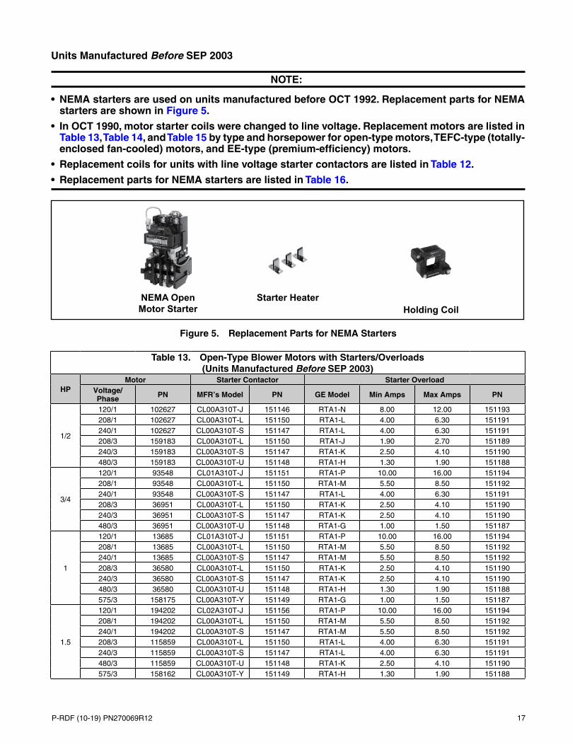
Units Manufactured Before SEP 2003
NOTE:
• NEMA starters are used on units manufactured before OCT 1992. Replacement parts for NEMA starters are shown in Figure 5.
• In OCT 1990, motor starter coils were changed to line voltage. Replacement motors are listed in Table 13, Table 14, and Table 15 by type and horsepower for open-type motors, TEFC-type (totally-enclosed fan-cooled) motors, and EE-type (premium-efficiency) motors.
• Replacement coils for units with line voltage starter contactors are listed in Table 12.
• Replacement parts for NEMA starters are listed in Table 16.
Figure 5. Replacement Parts for NEMA Starters
Table 13. Open-Type Blower Motors with Starters/Overloads (Units Manufactured Before SEP 2003)
HPMotor Starter Contactor Starter Overload
Voltage/Phase PN MFR’s Model PN GE Model Min Amps Max Amps PN
1/2
120/1 102627 CL00A310T-J 151146 RTA1-N 8.00 12.00 151193208/1 102627 CL00A310T-L 151150 RTA1-L 4.00 6.30 151191240/1 102627 CL00A310T-S 151147 RTA1-L 4.00 6.30 151191208/3 159183 CL00A310T-L 151150 RTA1-J 1.90 2.70 151189240/3 159183 CL00A310T-S 151147 RTA1-K 2.50 4.10 151190480/3 159183 CL00A310T-U 151148 RTA1-H 1.30 1.90 151188
3/4
120/1 93548 CL01A310T-J 151151 RTA1-P 10.00 16.00 151194208/1 93548 CL00A310T-L 151150 RTA1-M 5.50 8.50 151192240/1 93548 CL00A310T-S 151147 RTA1-L 4.00 6.30 151191208/3 36951 CL00A310T-L 151150 RTA1-K 2.50 4.10 151190240/3 36951 CL00A310T-S 151147 RTA1-K 2.50 4.10 151190480/3 36951 CL00A310T-U 151148 RTA1-G 1.00 1.50 151187
1
120/1 13685 CL01A310T-J 151151 RTA1-P 10.00 16.00 151194208/1 13685 CL00A310T-L 151150 RTA1-M 5.50 8.50 151192240/1 13685 CL00A310T-S 151147 RTA1-M 5.50 8.50 151192208/3 36580 CL00A310T-L 151150 RTA1-K 2.50 4.10 151190240/3 36580 CL00A310T-S 151147 RTA1-K 2.50 4.10 151190480/3 36580 CL00A310T-U 151148 RTA1-H 1.30 1.90 151188575/3 158175 CL00A310T-Y 151149 RTA1-G 1.00 1.50 151187
1.5
120/1 194202 CL02A310T-J 151156 RTA1-P 10.00 16.00 151194208/1 194202 CL00A310T-L 151150 RTA1-M 5.50 8.50 151192240/1 194202 CL00A310T-S 151147 RTA1-M 5.50 8.50 151192208/3 115859 CL00A310T-L 151150 RTA1-L 4.00 6.30 151191240/3 115859 CL00A310T-S 151147 RTA1-L 4.00 6.30 151191480/3 115859 CL00A310T-U 151148 RTA1-K 2.50 4.10 151190575/3 158162 CL00A310T-Y 151149 RTA1-H 1.30 1.90 151188
NEMA Open Motor Starter
Starter HeaterHolding Coil

18 P-RDF (10-19) PN270069R12
Table 13. Open-Type Blower Motors with Starters/Overloads (Units Manufactured Before SEP 2003)
HPMotor Starter Contactor Starter Overload
Voltage/Phase PN MFR’s Model PN GE Model Min Amps Max Amps PN
2
120/1 202581 CL25A310T-J 1024072 RTA1-T 17.50 22.00 151197208/1 202581 CL01A310T-L 151155 RTA1-N 8.00 12.00 151193240/1 202581 CL01A310T-S 151152 RTA1-N 8.00 12.00 151193208/3 159327 CL00A310T-L 151150 RTA1-M 5.50 8.50 151192240/3 159327 CL00A310T-S 151147 RTA1-M 5.50 8.50 151192480/3 159327 CL00A310T-U 151148 RTA1-K 2.50 4.10 151190575/3 158176 CL00A310T-Y 151149 RTA1-J 1.90 2.70 151189
3
208/1 111560 CL02A310T-L 151159 RTA1-P 10.00 16.00 151194240/1 111560 CL01A310T-S 151152 RTA1-P 10.00 16.00 151194208/3 159185 CL00A310T-L 151150 RTA1-N 8.00 12.00 151193240/3 159185 CL00A310T-S 151147 RTA1-N 8.00 12.00 151193480/3 159185 CL00A310T-U 151148 RTA1-L 4.00 6.30 151191575/3 120019 CL00A310T-Y 151149 RTA1-K 2.50 4.10 151190208/3 152002 — RTA1-N 8.00 12.00 151193240/3 152002 — RTA1-M 5.50 8.50 151192480/3 152002 — RTA1-K 2.50 4.10 151190
5
208/1 111562 CL04A310M-L 151169 RTA1-V 25.00 32.00 151199240/1 111562 CL04A310M-S 151166 RTA1-V 25.00 32.00 151199208/3 113371 CL01A310T-L 151155 RTA1-P 10.00 16.00 151194240/3 113371 CL01A310T-S 151152 RTA1-P 10.00 16.00 151194480/3 113371 CL00A310T-U 151148 RTA1-M 5.50 8.50 151192575/3 120020 CL00A310T-Y 151149 RTA1-L 4.00 6.30 151191
7.5
208/1 105828 CL06A311M-L 151173 RTA2-E 30.00 43.00 151206240/1 105828 CL45A310M-S 151170 RTA1-V 25.00 32.00 151199208/3 105855 CL25A310T-L 1024076 RTA1-U 21.00 26.00 1024078240/3 105855 CL25A310T-S 1024073 RTA1-T 17.50 22.00 1024078480/3 105855 CL01A310T-U 151153 RTA1-N 8.00 12.00 151193575/3 158164 CL00A310T-Y 151149 RTA1-M 5.50 8.50 151192
10
208/1 105830 CL06A311M-L 151173 RTA2-E 30.00 43.00 151206240/1 105830 CL06A311M-S 151172 RTA2-E 30.00 43.00 151206208/3 105857 CL04A310M-L 151169 RTA1-V 25.00 32.00 151199240/3 105858 CL04A310M-S 151166 RTA1-V 25.00 32.00 151199480/3 105858 CL01A310T-U 151153 RTA1-P 10.00 16.00 151194575/3 158163 CL01A310T-Y 151154 RTA1-P 10.00 16.00 151194
15
208/3 142287 CL06A311M-L 151173 RTA2-G 42.00 55.00 151202240/3 142288 CL06A311M-S 151172 RTA2-E 30.00 43.00 151206480/3 142288 CL25A310T-U 1024074 RTA1-T 17.50 22.00 1024078575/3 142289 CL02A310T-Y 151158 RTA1-S 14.50 18.00 151196
20
208/3 142295 CL07A311M-L 151176 RTA2-H 54.00 65.00 151203240/3 142296 CL07A311M-S 151175 RTA2-G 42.00 55.00 151202480/3 142296 CL04A310M-U 151167 RTA1-V 25.00 32.00 151199575/3 142297 CL25A310T-Y 1024075 RTA1-T 17.50 22.00 1024078
25
208/3 159021 CL09A311M-L 151179 RTA2-J 64.00 82.00 151204240/3 159022 CL08A311M-S 151177 RTA2-H 54.00 65.00 151203480/3 159022 CL45A310M-U 151171 RTA1-V 25.00 32.00 151199575/3 159023 CL04A310M-Y 151168 RTA1-U 21.00 26.00 151198
30
208/3 159024 CL09A311M-L 151179 RT2-J 64.00 82.00 151204240/3 159025 CL09A311M-S 151178 RT2-J 64.00 82.00 151204480/3 159025 CL06A311M-U 151174 RTA2-E 30.00 43.00 151206575/3 159026 CL04A310M-Y 119852 RTA1-V 25.00 32.00 151199
—Continued
BLOWER MOTOR, MOTOR CONTACTOR, AND STARTER CONTACTOR—CONTINUED
Units Manufactured Before SEP 2003—Continued
P-RDF (10-19) PN270069R12 19
Table 14. TEFC-Type Blower Motors with Starters/Overloads (Units Manufactured Before SEP 2003)
HPMotor Starter Contactor Starter Overload
Voltage/Phase PN MFR’s Model PN GE Model Min Amps Max Amps PN
1/2
120/1 159184 CL00A310T-J 151146 RTA1-M 5.50 8.50 151192208/1 159184 CL00A310T-L 151150 RTA1-K 2.50 4.10 151190240/1 159184 CL00A310T-S 151147 RTA1-K 2.50 4.10 151190208/3 16077 CL00A310T-L 151150 RTA1-J 1.90 2.70 151189240/3 16077 CL00A310T-S 151147 RTA1-J 1.90 2.70 151189480/3 16077 CL00A310T-U 151148 RTA1-F 0.65 1.10 151186575/3 105568 CL00A310T-Y 151149 RTA1-F 0.65 0.90 151186
3/4
120/1 115860 CL01A310T-J 151151 RTA1-P 10.00 16.00 151194208/1 115860 CL00A310T-L 151150 RTA1-L 4.00 6.30 151191240/1 115860 CL00A310T-S 151147 RTA1-L 4.00 6.30 151191208/3 20371 CL00A310T-L 151150 RTA1-J 1.90 2.70 151189240/3 20371 CL00A310T-S 151147 RTA1-J 1.90 2.70 151189480/3 20371 CL00A310T-U 151148 RTA1-G 1.00 1.50 151187575/3 105569 CL00A310T-Y 151149 RTA1-F 0.65 1.10 151186
1
120/1 174993 CL01A310T-J 151151 RTA1-P 10.00 16.00 151194208/1 174993 CL00A310T-S 151147 RTA1-M 5.50 8.50 151192240/1 174993 CL00A310T-S 151147 RTA1-M 5.50 8.50 151192208/3 16080 CL00A310T-L 151150 RTA1-K 2.50 4.10 151190240/3 16080 CL00A310T-S 151147 RTA1-K 2.50 4.10 151190480/3 16080 CL00A310T-U 151148 RTA1-H 1.30 1.90 151188575/3 105570 CL00A310T-Y 151149 RTA1-G 1.00 1.50 151187
1.5
120/1 94347 CL02A310T-J 151156 RTA1-S 14.50 18.00 151196208/1 94347 CL00A310T-L 151150 RTA1-N 8.00 12.00 151193240/1 94347 CL00A310T-S 151147 RTA1-N 8.00 12.00 151193208/3 101286 CL00A310T-L 151150 RTA1-L 4.00 6.30 151191240/3 101286 CL00A310T-S 151147 RTA1-L 4.00 6.30 151191480/3 101286 CL00A310T-U 151148 RTA1-J 1.90 2.70 151189575/3 105665 CL00A310T-Y 151149 RTA1-H 1.30 1.90 151188
2
120/1 105572 CL04A310M-J 151165 RTA1-U 21.00 26.00 151198240/1 105572 CL01A310T-S 151152 RTA1-P 10.00 16.00 151194208/3 158165 CL00A310T-L 151150 RTA1-M 5.50 8.50 151192240/3 158165 CL00A310T-S 151147 RTA1-L 4.00 6.30 151191480/3 158165 CL00A310T-U 151148 RTA1-K 2.50 4.10 151190575/3 158166 CL00A310T-Y 151149 RTA1-J 1.90 2.70 151189
3
120/1 111564 CL04A310M-J 151165 RTA1-V 25.00 32.00 151199240/1 111564 CL02A310T-S 151157 RTA1-P 10.00 16.00 151194208/3 159330 CL00A310T-L 151150 RTA1-N 5.50 8.50 151192240/3 159330 CL00A310T-S 151147 RTA1-N 5.50 8.50 151192480/3 159330 CL00A310T-U 151148 RTA1-K 2.50 4.10 151190575/3 111571 CL00A310T-Y 151149 RTA1-K 2.50 4.10 151190
5
240/1 111567 CL04A310M-S 151166 RTA1-T 17.50 22.00 151197208/3 155048 CL01A310T-L 151155 RTA1-S 14.50 18.00 151196240/3 155048 CL01A310T-S 151152 RTA1-P 10.00 16.00 151194480/3 155048 CL00A310T-U 151148 RTA1-L 4.00 6.30 151191575/3 158170 CL00A310T-Y 151149 RTA1-L 4.00 6.30 151191
7.5
240/1 105842 CL45A310M-S 151170 RTA1-W 30.00 40.00 151200208/3 158171 CL04A310M-L 151169 RTA1-U 21.00 26.00 151198240/3 158171 CL25A310T-S 1024073 RTA1-T 17.50 22.00 1024078480/3 158171 CL01A310T-U 151153 RTA1-N 8.00 12.00 151193575/3 158172 CL00A310T-Y 151149 RTA1-N 5.50 8.50 151192
10
240/1 105846 CL06A311M-S 151172 RTA2-E 30.00 43.00 151206208/3 158173 CL04A310M-L 151169 RTA1-V 25.00 32.00 151199240/3 158173 CL04A310M-S 151166 RTA1-U 21.00 26.00 151198480/3 158173 CL01A310T-U 151153 RTA1-P 10.00 16.00 151194575/3 158174 CL01A310T-Y 151154 RTA1-N 8.00 12.00 151193

20 P-RDF (10-19) PN270069R12
Table 14. TEFC-Type Blower Motors with Starters/Overloads (Units Manufactured Before SEP 2003)
HPMotor Starter Contactor Starter Overload
Voltage/Phase PN MFR’s Model PN GE Model Min Amps Max Amps PN
15240/3 142443 CL06A311M-S 151172 RTA2-E 30.00 43.00 151206480/3 142443 CL25A310T-U 1024074 RTA1-T 17.50 22.00 1024078575/3 142444 CL02A310T-Y 151158 RTA1-P 10.00 16.00 151194
20240/3 142301 CL07A311M-S 151175 RTA2-G 42.00 55.00 151202480/3 142301 CL04A310M-U 151167 RTA1-V 25.00 32.00 151199575/3 142302 CL25A310T-Y 1024075 RTA1-T 17.50 22.00 1024078
25
208/3 165321 CL09A311M-L 151179 RT2-J 64.00 82.00 151204240/3 165321 CL07A311M-S 151175 RT2-H 54.00 65.00 151203480/3 165321 CL04A310M-U 151167 RT1-V 25.00 32.00 151199575/3 165322 CL04A310M-Y 151168 RT1-U 21.00 26.00 151198
30
208/3 165323 CL10A311M-L 166756 RT2-L 78.00 97.00 151205240/3 165323 CL09A311M-S 151178 RT2-J 64.00 82.00 151204480/3 165323 CL06A311M-U 151174 RT2-E 30.00 43.00 151206575/3 165324 CL04A310M-Y 151168 RT1-V 25.00 32.00 151199
—Continued
Table 15. EE-Type Blower Motors with Starters/Overloads (Units Manufactured Before SEP 2003)
HPMotor Starter Contactor Starter Overload
Voltage/Phase PN MFR’s Model PN GE Model Min Amps Max Amps PN
1
208/3 105659 CL00A310T-L 151150 RTA1-K 2.50 4.10 151190240/3 159328 CL00A310T-S 151147 RTA1-K 2.50 4.10 151190480/3 159328 CL00A310T-U 151148 RTA1-G 1.00 1.50 151187575/3 158175 CL00A310T-Y 151149 RTA1-G 1.00 1.50 151187
1.5
208/3 105662 CL00A310T-L 151150 RTA1-L 4.00 6.30 151191240/3 159329 CL00A310T-S 151147 RTA1-K 2.50 4.10 151190480/3 159329 CL00A310T-U 151148 RTA1-J 1.90 2.70 151189575/3 158162 CL00A310T-Y 151149 RTA1-H 1.30 1.90 151188
2
208/3 105664 CL00A310T-L 151150 RTA1-L 4.00 6.30 151191240/3 159027 CL00A310T-S 151147 RTA1-L 4.00 6.30 151191480/3 159027 CL00A310T-U 151148 RTA1-K 2.50 4.10 151190575/3 158176 CL00A310T-Y 151149 RTA1-J 1.90 2.70 151189
3
208/3 159186 CL00A310T-L 151150 RTA1-N 8.00 12.00 151193240/3 159028 CL00A310T-S 151147 RTA1-N 5.50 8.50 151192480/3 159028 CL00A310T-U 151148 RTA1-K 2.50 4.10 151190575/3 159030 CL00A310T-Y 151149 RTA1-K 2.50 4.10 151190
5
208/3 159029 CL02A310T-L 151159 RTA1-P 10.00 16.00 151194240/3 159029 CL02A310T-S 151157 RTA1-P 10.00 16.00 151194480/3 159029 CL00A310T-U 151148 RTA1-M 5.50 8.50 151192575/3 111602 CL00A310T-Y 151149 RTA1-L 4.00 6.30 151191
7.5
208/3 159331 CL04A310M-L 151169 RTA1-U 21.00 26.00 151198240/3 159332 CL25A310T-S 1024073 RTA1-T 17.50 22.00 1024078480/3 159332 CL00A310T-U 151148 RTA1-N 8.00 12.00 151193575/3 158164 CL00A310T-Y 151149 RTA1-N 5.50 8.50 151192
10
208/3 159333 CL04A310M-L 151169 RTA1-V 25.00 32.00 151199240/3 159334 CL04A310M-S 151166 RTA1-U 21.00 26.00 151198480/3 159334 CL01A310T-U 151153 RTA1-P 10.00 16.00 151194575/3 158163 CL00A310T-Y 151149 RTA1-P 10.00 16.00 151194
15
208/3 142440 CL06A311M-L 151173 RTA2-E 30.00 43.00 151206240/1 142441 CL06A311M-S 151172 RTA2-E 30.00 43.00 151206480/3 142441 CL25A310T-U 1024074 RTA1-T 17.50 22.00 1024078575/3 142289 CL02A310T-Y 151158 RTA1-P 10.00 16.00 151194
BLOWER MOTOR, MOTOR CONTACTOR, AND STARTER CONTACTOR—CONTINUED
Units Manufactured Before SEP 2003—Continued

P-RDF (10-19) PN270069R12 21
Table 15. EE-Type Blower Motors with Starters/Overloads (Units Manufactured Before SEP 2003)
HPMotor Starter Contactor Starter Overload
Voltage/Phase PN MFR’s Model PN GE Model Min Amps Max Amps PN
15
208/3 142440 CL06A311M-L 151173 RTA2-E 30.00 43.00 151206240/1 142441 CL06A311M-S 151172 RTA2-E 30.00 43.00 151206480/3 142441 CL25A310T-U 1024074 RTA1-T 17.50 22.00 1024078575/3 142289 CL02A310T-Y 151158 RTA1-P 10.00 16.00 151194
20
208/3 159187 CL07A311M-L 151176 RTA2-H 54.00 65.00 151203240/3 142299 CL06A311M-S 151172 RTA2-G 42.00 55.00 151202480/3 142299 CL04A310M-U 151167 RTA1-U 21.00 26.00 151198575/3 142300 CL25A310T-Y 1024075 RTA1-T 17.50 22.00 1024078
25208/3 159031 CL09A311M-L 151179 RT2-J 64.00 82.00 151204240/3 159033 CL08A311M-S 151177 RT2-H 54.00 65.00 151203480/3 159033 CL04A310M-U 151167 RT1-V 25.00 32.00 151199
30208/3 159032 CL10A311M-L 166756 RT2-L 78.00 97.00 151205240/3 159034 CL09A311M-S 151178 RT2-J 64.00 82.00 151204480/3 159034 CL06A311M-U 151174 RT2-E 30.00 43.00 151206
—Continued
Table 16. Replacement Parts for NEMA StartersStarter Model Starter Model
Size Coil Voltage
GE Model
RDF-1 RDF-2 RDF-3Size Coil
VoltageGE
ModelRDF-1 RDF-2 RDF-3
PN PN
0
24 CR306B024 39919 39919 39919
2
24 CR306D024 — 39921 39921115 CR306B002 111523 — 208 CR306D023 — 111528 111528208 CR306B023 111524 111524 — 230 CR306D003 — 111529 111529230 CR306B003 111525 111525 — 460 CR306D004 — 111530 111530460 CR306B004 111522 111522 111522
3
24 CR306E024 — 39922 39922
1
24 CR306C024 39920 39920 39920 208 CR306E023 — 111531 111531115 CR306C002 111526 — 230 CR306E003 — 111533208 CR306C023 111499 111499 — 460 CR306E004 — 111532230 CR306C003 111521 111521 — 575 CR306E004 — 119852
460 CR306C004 111527 111527 — 424 CR306F024 — 91519208 CR306F023 — 111534
Heater Heater
HP Voltage/Phase GE Model PN HP Voltage/
Phase GE Model PN
5
208/3 CR123C18.0B 89941 or 11061715
208/3 CR123F56.7B 91543208/3 CR123C19.8B 91542 230/3 CR123FC40.0B 89933230/3 CR123C16.3B 16193 or 110626 460/3 CR123C21.4B 19556460/3 CR123C8.67A 16192 or 110619
20208/3 CR123F77.28B 91544
7.5208/3 CR123C25.0B 16196 230/3 CR123F65.8B 91545230/3 CR123C22.8B 89924 or 110622
25208/3 CR123F91.4B 91546
460/3 CR123C12.5B 17257 or 110624 230/3 CR123F77.28B 91544
10
208/3 CR123C33.0B 89947 or 110625 460/3 CR123C36.6B 16195230/3 CR123C30.3B 89949 or 110627
30
208/3 CR123F10.4C 91547
460/3CR123C137B 110623 230/3 CR123F91.4B 91546
CR123C16.3B 16193 or 110626460/3 FA30B 119851575/3 F327B 121175
Holding Coil Holding CoilSize Coil Voltage GE Model PN Size Coil Voltage GE Model PN
0/1
24 15D21G024 485312
230 15D22G003 111928115 15D21G002 48507 460 15D22G004 111929208 15D21G023 48509
3
24 55-501336G024 95093230 15D21G003 73795 208 55-501336G023 111931460 15D21G004 48512 230 55-501336G003 111933575 15D21G005 73601 460 55-501336G004 111932
224 15D22G024 93957
424 55-501463G024 102816
208 15D22G023 111927 208 55-501463G023 111935
22 P-RDF (10-19) PN270069R12
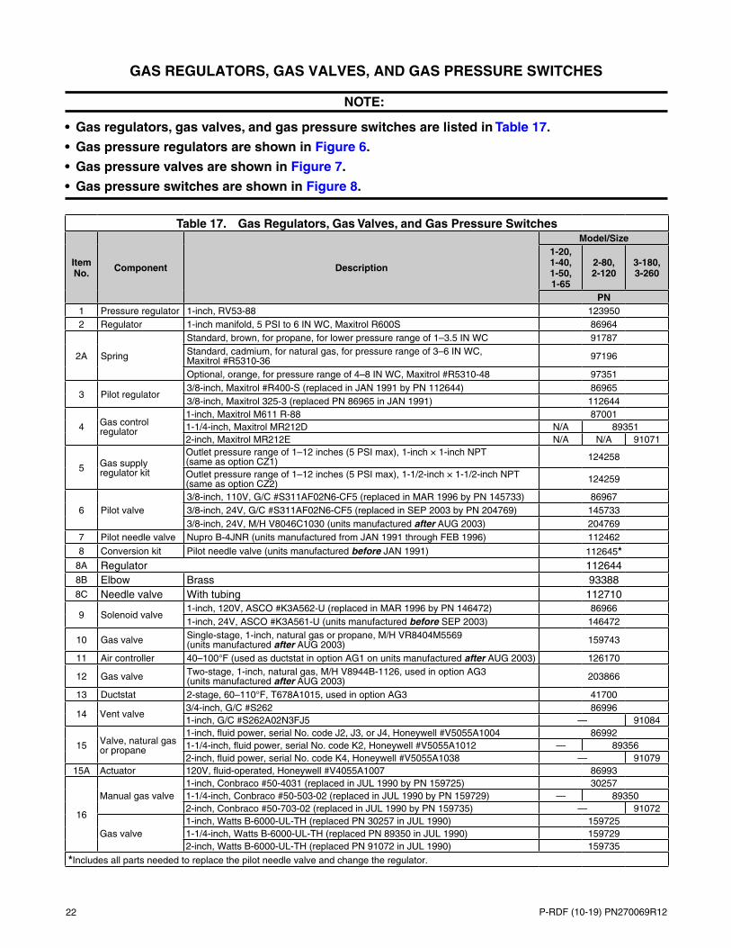
GAS REGULATORS, GAS VALVES, AND GAS PRESSURE SWITCHES
NOTE:
• Gas regulators, gas valves, and gas pressure switches are listed in Table 17.
• Gas pressure regulators are shown in Figure 6.
• Gas pressure valves are shown in Figure 7.
• Gas pressure switches are shown in Figure 8.
Table 17. Gas Regulators, Gas Valves, and Gas Pressure Switches
Item No. Component Description
Model/Size1-20, 1-40, 1-50, 1-65
2-80, 2-120
3-180, 3-260
PN1 Pressure regulator 1-inch, RV53-88 1239502 Regulator 1-inch manifold, 5 PSI to 6 IN WC, Maxitrol R600S 86964
2A Spring
Standard, brown, for propane, for lower pressure range of 1–3.5 IN WC 91787Standard, cadmium, for natural gas, for pressure range of 3–6 IN WC, Maxitrol #R5310-36 97196
Optional, orange, for pressure range of 4–8 IN WC, Maxitrol #R5310-48 97351
3 Pilot regulator3/8-inch, Maxitrol #R400-S (replaced in JAN 1991 by PN 112644) 869653/8-inch, Maxitrol 325-3 (replaced PN 86965 in JAN 1991) 112644
4 Gas control regulator
1-inch, Maxitrol M611 R-88 870011-1/4-inch, Maxitrol MR212D N/A 893512-inch, Maxitrol MR212E N/A N/A 91071
5 Gas supply regulator kit
Outlet pressure range of 1–12 inches (5 PSI max), 1-inch × 1-inch NPT (same as option CZ1) 124258
Outlet pressure range of 1–12 inches (5 PSI max), 1-1/2-inch × 1-1/2-inch NPT (same as option CZ2) 124259
6 Pilot valve3/8-inch, 110V, G/C #S311AF02N6-CF5 (replaced in MAR 1996 by PN 145733) 869673/8-inch, 24V, G/C #S311AF02N6-CF5 (replaced in SEP 2003 by PN 204769) 1457333/8-inch, 24V, M/H V8046C1030 (units manufactured after AUG 2003) 204769
7 Pilot needle valve Nupro B-4JNR (units manufactured from JAN 1991 through FEB 1996) 112462
8 Conversion kit Pilot needle valve (units manufactured before JAN 1991) 112645*8A Regulator 1126448B Elbow Brass 933888C Needle valve With tubing 112710
9 Solenoid valve1-inch, 120V, ASCO #K3A562-U (replaced in MAR 1996 by PN 146472) 869661-inch, 24V, ASCO #K3A561-U (units manufactured before SEP 2003) 146472
10 Gas valve Single-stage, 1-inch, natural gas or propane, M/H VR8404M5569 (units manufactured after AUG 2003) 159743
11 Air controller 40–100°F (used as ductstat in option AG1 on units manufactured after AUG 2003) 126170
12 Gas valve Two-stage, 1-inch, natural gas, M/H V8944B-1126, used in option AG3 (units manufactured after AUG 2003) 203866
13 Ductstat 2-stage, 60–110°F, T678A1015, used in option AG3 41700
14 Vent valve3/4-inch, G/C #S262 869961-inch, G/C #S262A02N3FJ5 — 91084
15 Valve, natural gas or propane
1-inch, fluid power, serial No. code J2, J3, or J4, Honeywell #V5055A1004 869921-1/4-inch, fluid power, serial No. code K2, Honeywell #V5055A1012 — 893562-inch, fluid power, serial No. code K4, Honeywell #V5055A1038 — 91079
15A Actuator 120V, fluid-operated, Honeywell #V4055A1007 86993
16
Manual gas valve1-inch, Conbraco #50-4031 (replaced in JUL 1990 by PN 159725) 302571-1/4-inch, Conbraco #50-503-02 (replaced in JUL 1990 by PN 159729) — 893502-inch, Conbraco #50-703-02 (replaced in JUL 1990 by PN 159735) — 91072
Gas valve1-inch, Watts B-6000-UL-TH (replaced PN 30257 in JUL 1990) 1597251-1/4-inch, Watts B-6000-UL-TH (replaced PN 89350 in JUL 1990) 1597292-inch, Watts B-6000-UL-TH (replaced PN 91072 in JUL 1990) 159735
*Includes all parts needed to replace the pilot needle valve and change the regulator.

P-RDF (10-19) PN270069R12 23
Table 17. Gas Regulators, Gas Valves, and Gas Pressure Switches
Item No. Component Description
Model/Size1-20, 1-40, 1-50, 1-65
2-80, 2-120
3-180, 3-260
PN
16B Adapter with test port
1-inch, ball valve 1107581-1/4-inch, ball valve 1107592-inch, ball valve 110760
17 Pilot gas valve 3/8-inch, manual 15972018 Vent valve 3/4-inch, 24V, NO (not shown) 124010
19
Pressure switch
Low gas pressure, automatic reset (replaced PN 93849 in SEP 2003) 204375**Low gas pressure, automatic reset, set at 50% of minimum inlet gas pressure as stated on unit rating plate, Antunes #RLGP-A (replaced in SEP 2003 by PN 204375)
93849
20
High gas pressure, manual reset (replaced PN 93850 in SEP 2003) 204297**High gas pressure, manual reset, set at 125% of normal manifold gas pressure as stated on unit rating plate, Antunes #HGP-AMI (replaced in SEP 2003 by PN 204297)
93850
21 Vent limiter Maxitrol #12A09 (used with pressure switches) 123481
**Includes built-in vent limiter.
—Continued
Figure 6. Gas Pressure Regulators (Refer to Table 17)
Item 2: Regulator and Item 2A: Spring
Item 3: Pilot Regulator
PN 112644
Item 1: Pressure Regulator
Item 4: Gas Control Regulator
PN 87001 PNs 89351 and 91071
Item 5: Gas Supply Regulator Kit
PN 86965

24 P-RDF (10-19) PN270069R12
Figure 7. Gas Pressure Valves (Refer to Table 17)
Figure 8. Gas Pressure Switches (Refer to Table 17)
GAS REGULATORS, GAS VALVES, AND GAS PRESSURE SWITCHES—CONTINUED
Item 7: Pilot Needle Valve
Item 9: Solenoid Valve
8A
8C
8B
Item 10: Single-Stage Gas Valve
Item 11: Air Controller
PN 146472
Item 12: Two-Stage Gas Valve
Item 13: Ductstat
Item 8: Pilot Needle Valve Conversion Kit
Item 15: Valve and Item 15A: Actuator
Item 6: Pilot Valve
PN 145733 PN 204769
Item 16: Gas Valve and Adapter
Item 17: Pilot Gas Valve
Item 14: Vent Valve
PN 86967
PN 86966
Item 19: Low Gas Pressure Switch Item 21: Vent Limiter
PN 204375 PN 204297PN 93849
Item 20: High Gas Pressure Switch
PN 93850

P-RDF (10-19) PN270069R12 25
MODULATING GAS CONTROL COMPONENTS
NOTE:
• When replacing a temperature sensor (item 1) on a Maxitrol MV-9 system (option AG33), check the model number on the sensor. PN 119617 or 194160 is used on units manufactured after JAN 1992. PN 87041 is used on units manufactured before FEB 1992.
• Sensors are not interchangeable and MUST match the amplifier.
• To replace the amplifier (item 3): for PN 148590 (model A1014L or A1014U) or PN 86976, order replacement kit PN 268301; for PN 194159 (model A1044CL), PN 157915 (model A1044EL), PN 119616 (model A1044E), or PN 86989 (model A1044), order replacement kit PN 268302.
• Amplifiers are not interchangeable and MUST match the sensor.
• Modulating gas control components are listed in Table 18 and shown in Figure 9.
Table 18. Modulating Gas Control ComponentsItem No. Component Description PN Gas Control
OptionSerial No.
Suffix Location
1 Temperature sensor
Maxitrol series 14, #TS114 90324 AG30, AG31 MV-7
Discharge
Maxitrol series 14A, #TS114A 87106 AG32 MV-8Maxitrol series 14B, #TS114B 123944 AG35 MV-8Maxitrol series 44, #TS144E, 120°F max 119617
AG33 MV-9Maxitrol series 44, #TS144C, 140°F max 194160Maxitrol series 94, #TS194 133228 AG36 MV-B
2 Mixing tube Maxitrol MTI-12 90323AG30, AG31, AG32, AG33, AG35, AG36
MV-7, MV-8, MV-9, MV-B
3 AmplifierMaxitrol series 14 and 14A, #A1014R 148590 AG30, AG31,
AG32 MV-7, MV-8
Electrical control
compartment
Maxitrol series 44, #A1044U (shown without cover) 268274 AG33 MV-9Maxitrol series 94, A1494 133229 AG36 MV-B
3A Replacement kit
Amplifier, for PN 148590 (model A1014L or A1014U) or PN 86976 268301 AG30, AG31,
AG32 MV-7, MV-8
Amplifier, for PN 194159 (model 1044CL), PN 157915 (model A1044EL), PN 119616 (model A1044E), or PN 86989 (model A1044)
268302 AG33 MV-9
4 Signal conditioner Maxitrol (for computer control) 134170 AG37 MV-C
5 Temperature selector
Maxitrol series 14, #TD114, range 55–90°F, selector with box (PN 156085), US installations 86988
AG30, AG31 MV-7
RemoteMaxitrol series 14, #TD114, range 50–75°F, Canadian installations 101165
Maxitrol series 14A, #TD114A, range 80–130°F 87107 AG32 MV-8Maxitrol series 14B, #TD114B, range 120–160°F 159285
AG35 MV-8Maxitrol series 14B, #TD114B, range 120–140°F 123943Selectrastat, Maxitrol series 44, #T-244 86990 AG33 MV-9 SpaceMaxitrol series 94, #TD294E-609-0818, 120°F, dual selector for paint booth applications (option AG36) 133230
AG36 MV-B RemoteMaxitrol series 94, #TD294E-609-0818, 160°F 159287
6 Thermostat Overriding, series 14, #T115 24857 AG31 MV-7, MV-8 Space

26 P-RDF (10-19) PN270069R12
Figure 9. Modulating Gas Control Components (Refer to Table 18)
MODULATING GAS CONTROL COMPONENTS—CONTINUED
IGNITION SYSTEM COMPONENTS
NOTE:
• The spark ignition system was discontinued in MAR 1996. at which point the ignition system was changed to a hot surface ignition system.
• Hot surface ignition components are listed in Table 19 and shown in Figure 10.
• Spark ignition components are listed in Table 20 and shown in Figure 11.
Item 1: Temperature Sensor Item 2: Mixing Tube
Item
PN 268274
Item 4: Signal Conditioner
PN 133229
Item 6: Overriding Thermostat
Item 5: Temperature Selector
PN 133230PN 86990
PN 148590
PNs 86988, 101165, 87107, and 159285

P-RDF (10-19) PN270069R12 27
Table 19. Hot Surface Ignition System Components (Units Manufactured After FEB 1996)Item No. Component Description PN
1Ignition module (located in electrical control compartment)
RAM #H4MC24-01, serial No. ignition system code 72 (units manufactured from MAR 1996 through AUG 2003) 157953
Synetek IH11040B-C, single-flame rod, serial No. ignition system code 82, used on series 3 units with burner sizes 250–1500 MBH (options BL1–BL6) (units manufactured after AUG 2003)
204376
Synetek IH11040C-C, dual-flame rod, serial No. ignition system code 81, used on series 3 units with burner sizes 1750–3000 MBH (options BL7–BL13) (units manufactured after AUG 2003)
204166
2 Pilot assembly For units manufactured before SEP 2003 1200482A Pilot 1228402B Flame sensor J/C #Y75MK-1D 1347062C Screw #8 × 1/2-inch long 385292D Bushing Pilot 1217302E Capscrew Hex head, #10-32 × 3/8-inch long 901672F Ignitor Hot surface, Norton #401E 121865
3 Pilot250–1500 MBH (units manufactured after AUG 2003) 1279101750–3000 MBH (units manufactured after AUG 2003) 122840
4 Ignitor Hot surface, Norton #401E (units manufactured after AUG 2003) 121865
5 Flame sensor* J/C #Y75MK-1D (units manufactured after AUG 2003) 134706
6 Ignition conversion kit** (not shown)
For unit with 200VA transformer 146268For 115V unit with 80VA transformer 146318For 208V, 240V, 480V, or 575V unit with 80VA transformer 146319
*For replacement of the flame sensor at the ignitor end of the burner only. 1750–3000 MBH burners have a second flame sensor (PN 210767).
**For converting to hot surface ignition from a spark pilot with either a rectification type or ultraviolet flame sensor.
Figure 10. Hot Surface Ignition System Components—Units Manufactured After FEB 1996 (Refer to Table 19)
Pilot and Ignitor
Flame Sensor
Item 1: Ignition Module
PN 204376
PN 204166
Items 3, 4, and 5: Pilot, Ignitor, and Flame Sensor
Location (not shown)3
4
5
PN 157953
Item 2: Pilot Assembly
28 P-RDF (10-19) PN270069R12
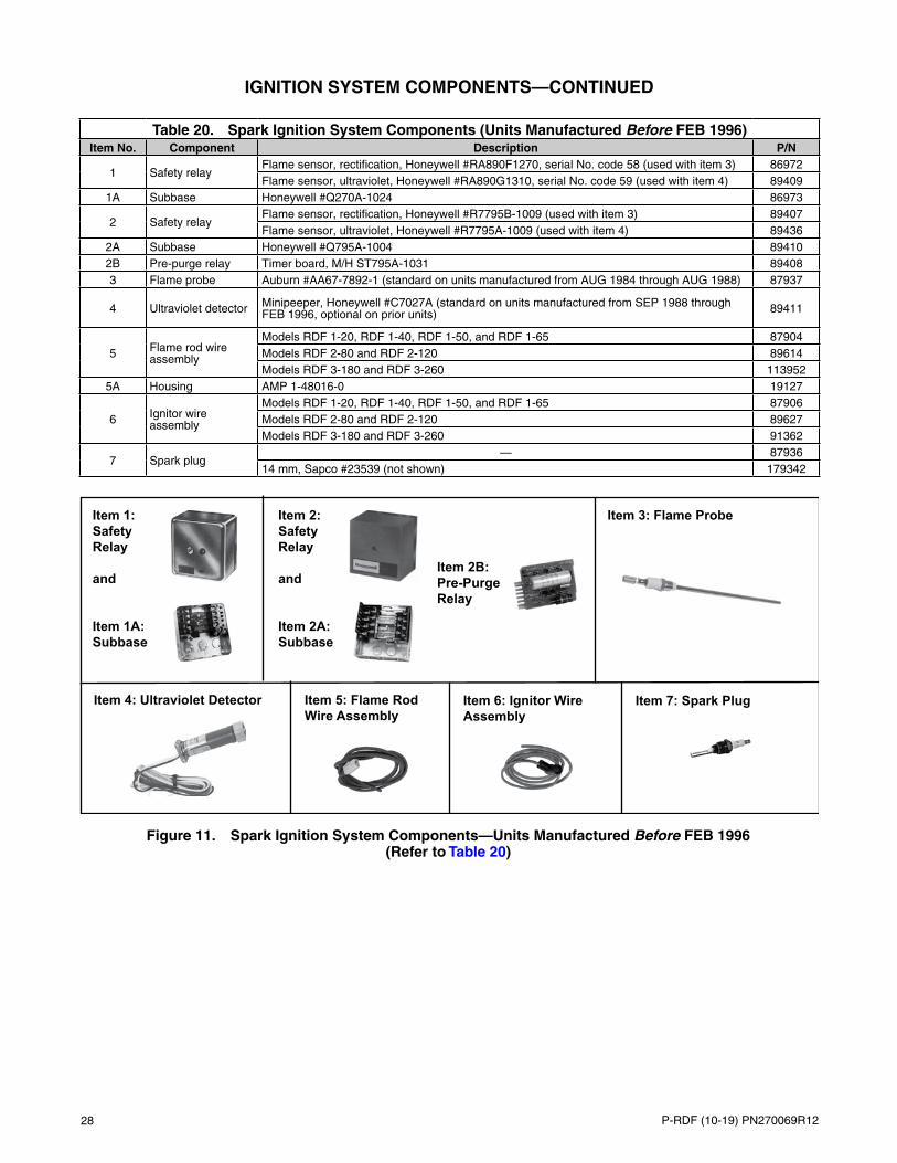
Table 20. Spark Ignition System Components (Units Manufactured Before FEB 1996)Item No. Component Description P/N
1 Safety relayFlame sensor, rectification, Honeywell #RA890F1270, serial No. code 58 (used with item 3) 86972Flame sensor, ultraviolet, Honeywell #RA890G1310, serial No. code 59 (used with item 4) 89409
1A Subbase Honeywell #Q270A-1024 86973
2 Safety relayFlame sensor, rectification, Honeywell #R7795B-1009 (used with item 3) 89407Flame sensor, ultraviolet, Honeywell #R7795A-1009 (used with item 4) 89436
2A Subbase Honeywell #Q795A-1004 894102B Pre-purge relay Timer board, M/H ST795A-1031 894083 Flame probe Auburn #AA67-7892-1 (standard on units manufactured from AUG 1984 through AUG 1988) 87937
4 Ultraviolet detector Minipeeper, Honeywell #C7027A (standard on units manufactured from SEP 1988 through FEB 1996, optional on prior units) 89411
5 Flame rod wire assembly
Models RDF 1-20, RDF 1-40, RDF 1-50, and RDF 1-65 87904Models RDF 2-80 and RDF 2-120 89614Models RDF 3-180 and RDF 3-260 113952
5A Housing AMP 1-48016-0 19127
6 Ignitor wire assembly
Models RDF 1-20, RDF 1-40, RDF 1-50, and RDF 1-65 87906Models RDF 2-80 and RDF 2-120 89627Models RDF 3-180 and RDF 3-260 91362
7 Spark plug— 87936
14 mm, Sapco #23539 (not shown) 179342
IGNITION SYSTEM COMPONENTS—CONTINUED
Figure 11. Spark Ignition System Components—Units Manufactured Before FEB 1996 (Refer to Table 20)
Item 1: Safety Relay and Item 1A: Subbase
Item 2: Safety Relay and Item 2A: Subbase
Item 2B: Pre-Purge Relay
Item 3: Flame Probe
Item 4: Ultraviolet Detector Item 5: Flame Rod Wire Assembly
Item 6: Ignitor Wire Assembly
Item 7: Spark Plug

P-RDF (10-19) PN270069R12 29
BURNER COMPONENTS
NOTE:
• Units manufactured after AUG 2003 use Midco HMA-700 series burners, which include the burner, the mixing plates, and the end plate. 1,750–3,000 MBH (42- to 60-inch) burners also include a second sensor (PN 210767).
• Burner components for units manufactured after AUG 2003 are listed in Table 21 and shown in Figure 12.
• Burner components for units manufactured before SEP 2003 are listed in Table 22 and shown in Figure 13.
Table 21. Burner Components (Units Manufactured After AUG 2003)Component Description PN
Burner, Midco HMA-700 series (includes burner, mixing plates, and end plate)
6-inch, 250-MBH (option BL1) 20331212-inch, 500-MBH (option BL2) 20331318-inch, 750-MBH (option BL3) 20331424-inch, 1000-MBH (option BL4) 20331530-inch, 1250-MBH (option BL5) 20331636-inch, 1500-MBH (option BL6) 20331742-inch, 1750-MBH (option BL7)
20331842-inch, 2000-MBH (option BL8)48-inch, 2250-MBH (option BL9) 20331954-inch, 2500-MBH (option BL10) 20332060-inch, 2750-MBH (option BL11)
20332160-inch, 3000-MBH (option BL12)
Second sensor assemblyWith bracket, used on 42- to 60-inch burners (at end of burner opposite ignitor) 210767
Sensor only 210766
Figure 12. Burner Assembly—Units Manufactured After AUG 2003
Mixing Plates
Ignitor
Gas Supply
Pilot Assembly
Burner End Plate
Sensor
Burner
30 P-RDF (10-19) PN270069R12
BURNER COMPONENTS—CONTINUED
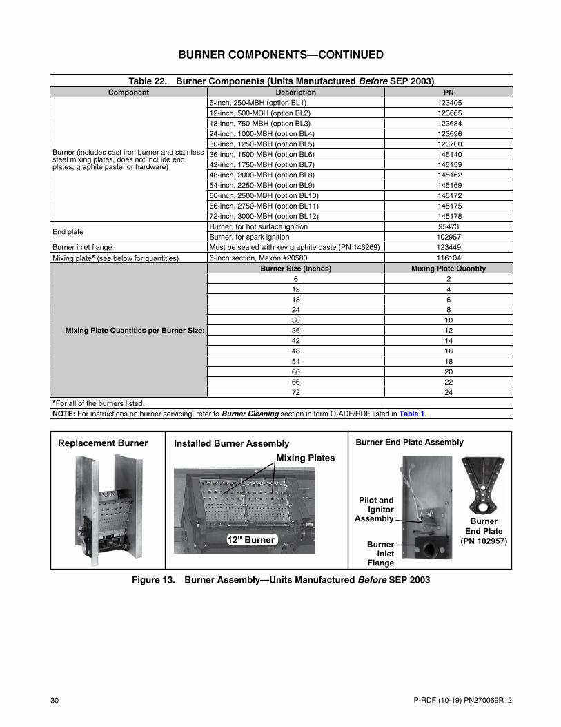
Table 22. Burner Components (Units Manufactured Before SEP 2003)Component Description PN
Burner (includes cast iron burner and stainless steel mixing plates, does not include end plates, graphite paste, or hardware)
6-inch, 250-MBH (option BL1) 12340512-inch, 500-MBH (option BL2) 12366518-inch, 750-MBH (option BL3) 12368424-inch, 1000-MBH (option BL4) 12369630-inch, 1250-MBH (option BL5) 12370036-inch, 1500-MBH (option BL6) 14514042-inch, 1750-MBH (option BL7) 14515948-inch, 2000-MBH (option BL8) 14516254-inch, 2250-MBH (option BL9) 14516960-inch, 2500-MBH (option BL10) 14517266-inch, 2750-MBH (option BL11) 14517572-inch, 3000-MBH (option BL12) 145178
End plateBurner, for hot surface ignition 95473Burner, for spark ignition 102957
Burner inlet flange Must be sealed with key graphite paste (PN 146269) 123449
Mixing plate* (see below for quantities) 6-inch section, Maxon #20580 116104
Mixing Plate Quantities per Burner Size:
Burner Size (Inches) Mixing Plate Quantity6 212 418 624 830 1036 1242 1448 1654 1860 2066 2272 24
*For all of the burners listed.NOTE: For instructions on burner servicing, refer to Burner Cleaning section in form O-ADF/RDF listed in Table 1.
Figure 13. Burner Assembly—Units Manufactured Before SEP 2003
Installed Burner AssemblyMixing Plates
Burner End Plate Assembly
Burner Inlet
Flange
Pilot and Ignitor
Assembly
12" Burner
Burner End Plate
(PN 102957)
Replacement Burner

P-RDF (10-19) PN270069R12 31
DAMPER COMPONENTS
NOTE:
• Damper locations are shown in Figure 14.
• Damper components for units manufactured after AUG 2003 are listed in Table 23 and shown in Figure 15.
• Damper components for units manufactured before SEP 2003 are listed in Table 24 and shown in Figure 16.
Figure 14. Damper and Damper Control Locations
Units Manufactured After AUG 2003
KEY: 1 Burner 2 Discharge damper motor (options AR19 and AR20) 3 Discharge damper (options AR19 and AR20) 4 Manual reset limit 5 Automatic limit 6 Discharge air sensor 7 Blower motor 8 Damper motor (optional) 9 Return air damper (options AR22 and AR23)10 Bypass damper (options AR19, AR20, AR22, and AR23)
Sizes 2-80, 2-120, 3-180, 3-260
In Electrical Compartment—Sizes 1-20, 1-40, 1-50, 1-65Sizes 2-80, 2-120,
3-180, 3-260
Outside Air
Hood
Units Manufactured Before SEP 2003
Remote Pressure Null Switch

32 P-RDF (10-19) PN270069R12
Table 23. Damper Arrangements and Linkage Components (Units Manufactured After AUG 2003)
Item No. Component Damper
Arrangement Description OptionModel
RDF-1 RDF-2 RDF-3
PN (Quantity)*
1 Damper (not shown)
Discharge21-1/8 × 18-1/2 inches
AQ3, AQ4, AR19, AR20, AR33, AR36
15869 —27-1/4 × 27-1/4 inches — 89355 —37 × 37 inches — 91073
Return air26 × 12 inches
AR22, AR23, AR34, AR37203602 —
Bypass AR19, AR20, AR22, AR23, AR33, AR34, AR36, AR37
Return air53-1/2 × 17-3/4 inches
AR22, AR23, AR34, AR37— 203604 —
Bypass AR19, AR20, AR22, AR23, AR33, AR34, AR36, AR37
Return air65-3/4 × 20 inches
AR22, AR23, AR34, AR37— 203603
Bypass AR19, AR20, AR22, AR23, AR33, AR34, AR36, AR37
2 Motor
Discharge
Two-position, 100% makeup air, J/C #M9216-BGC-2 AQ3, AQ4 159892
Modulating, with manual potentiometer, J/C #M9216-JGA-2 (not shown) AR19 204269
Discharge Modulating, with automatic pressure switch, AF24-MFT95-US
AR20159877
Return air AR22Discharge Modulating, with computer control through
signal conditioner, J/C #M9216-GGC-2AR33
204271Return air AR34Discharge Modulating, with photohelic pressure
sensor, J/C #M9109-AGA-2AR36
204270Return air AR37
Return air Modulating, with automatic pressure switch, J/C #M9109-AGA-2 AR23
Bypass Modulating, J/C #M9108-AGD-2 AR19, AR20, AR22, AR23, AR33, AR34, AR36, AR37 204268
3 Damper rod (not shown)
Vertical discharge
1/4 × 16 inches (units manufactured before NOV 2007) AQ3
112555 —Horizontal discharge
1/4 × 16 inches (units manufactured before NOV 2007) AQ4
Vertical discharge 1/4 × 7-1/2 inches AQ3 — 89640
Horizontal discharge
1/4 × 38 inchesAQ4
— 89970 —1/4 × 24 inches — 91428
Return air 1/4 × 7-7/8 inches AR34, AR37 5120 —
4 Damper crank arm Linkage M/H #26026K AR22, AR23, AR34 12635 —
5 Damper crank arm kit Linkage
M/H #26026K (units manufactured before NOV 2007) AQ3, AQ4 12635
—AQ3, AQ4 — 66278
AR34, AR37 66278 —W/R #135-0002 AQ4 — 66277J/C #9000-153 AR22, AR23 194200 —J/C #9000-153 (units manufactured before NOV 2007) AQ3 194200
6 Ball joint LinkageM/H #27518 AR19, AR20, AR22, AR23,
AR34, AR37 12636 (2) —
M/H #27518 (units manufactured before NOV 2007) AQ3, AQ4 12636 (2)
*Quantity is one (1) unless otherwise indicated.
DAMPER COMPONENTS—CONTINUED

P-RDF (10-19) PN270069R12 33
Figure 15. Damper Components—Units Manufactured After AUG 2003 (Refer to Table 23)
Table 24. Damper Arrangements and Linkage Components (Units Manufactured Before SEP 2003)
Item No. Component Damper
Arrangement Description OptionModel
RDF-1 RDF-2 RDF-3
PN (Quantity)*
1 Damper
Discharge22 × 18 inches
AQ3, AQ4, AR19, AR2086999 —
28 × 28 inches — 89355 —37 × 37 inches — 91073
Return32 × 10 inches
AR22, AR2387117 —
Bypass AR19, AR20, AR22, AR23Return
22 × 54 inchesAR22, AR23
— 89354 —Bypass AR19, AR20, AR22, AR23Return
30 × 68 inchesAR22, AR23
— 91074Bypass AR19, AR20, AR22, AR23
2Damper adjustment arm
Bypass — AR 22, 23 111309
3 Motor
Discharge
Two-position, 100% makeup air, M/H #M8415A1004
AQ3, AQ487000 —
Two-position, 100% makeup air, W/R #3402-9 — 97385
Discharge Modulating, with manual potentiometer, M/H #M9175A1015 (replaces PN 53928)
AR19115681**
Return air AR22Discharge
Modulating, with photohelic pressure switch, M/H #M6414A1009
AR2087116 —Return air AR23
Bypass AR19, AR20, AR22, AR23Discharge
Modulating, with photohelic pressure switch, M/H #M6194B1011 (replaces PN 87059)
AR20— 115683**Return air AR23
Bypass AR19, AR20, AR22, AR23
*Quantity is one (1) unless otherwise indicated.
**When installing replacement motors (PN 115681 or 115683) to replace PN 53928 or 87059, it is necessary to change the damper motor crank arm. Order PN 116209.
Item 4: Damper Crank Arm
Item 6: Ball Joint
Item 2: Damper Motor
PN 159877 PN 204270 PN 204268PN 204271
PN 194200 PN 66278 PN 66277
PN 159892
Item 5: Damper Crank Arm Kit
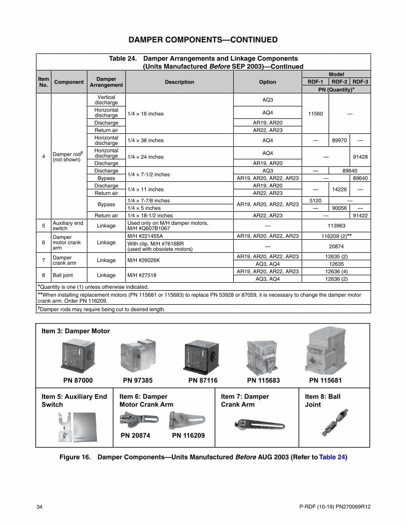
34 P-RDF (10-19) PN270069R12
—ContinuedTable 24. Damper Arrangements and Linkage Components
(Units Manufactured Before SEP 2003)
Item No. Component Damper
Arrangement Description OptionModel
RDF-1 RDF-2 RDF-3
PN (Quantity)*
4 Damper rod† (not shown)
Vertical discharge
1/4 × 16 inches
AQ3
11560 —Horizontal discharge AQ4
Discharge AR19, AR20Return air AR22, AR23Horizontal discharge 1/4 × 38 inches AQ4 — 89970 —
Horizontal discharge 1/4 × 24 inches
AQ4— 91428
Discharge AR19, AR20Discharge
1/4 × 7-1/2 inchesAQ3 — 89640
Bypass AR19, AR20, AR22, AR23 — 89640Discharge
1/4 × 11 inchesAR19, AR20
— 14226 —Return air AR22, AR23
Bypass1/4 × 7-7/8 inches
AR19, AR20, AR22, AR235120 —
1/4 × 5 inches — 90056 —Return air 1/4 × 18-1/2 inches AR22, AR23 — 91422
5 Auxiliary end switch Linkage Used only on M/H damper motors,
M/H #Q607B1067 — 113963
6Damper motor crank arm
LinkageM/H #221455A AR19, AR20, AR22, AR23 116209 (2)**With clip, M/H #7616BR (used with obsolete motors) — 20874
7 Damper crank arm Linkage M/H #26026K
AR19, AR20, AR22, AR23 12635 (2)AQ3, AQ4 12635
8 Ball joint Linkage M/H #27518AR19, AR20, AR22, AR23 12636 (4)
AQ3, AQ4 12636 (2)
*Quantity is one (1) unless otherwise indicated.
**When installing replacement motors (PN 115681 or 115683) to replace PN 53928 or 87059, it is necessary to change the damper motor crank arm. Order PN 116209.†Damper rods may require being cut to desired length.
DAMPER COMPONENTS—CONTINUED
Figure 16. Damper Components—Units Manufactured Before AUG 2003 (Refer to Table 24)
Item 3: Damper Motor
PN 87000 PN 97385 PN 115681PN 87116 PN 115683
Item 5: Auxiliary End Switch
PN 116209
Item 6: Damper Motor Crank Arm
Item 7: Damper Crank Arm
Item 8: Ball Joint
PN 20874

P-RDF (10-19) PN270069R12 35
Table 25. Blower- and Motor-Mounting Components
Item No. Component Description
Model1-20 1-40 1-50 1-65 2-80 2-120 3-180 3-260
PN (Quantity)*
1Blower with shaft and bearings
10-inch, #A10-10AC 1357 —12-inch, #A12-12AC — 1360 —15-inch, #A15-15A — 86983 —18-inch, class 1, 1-inch shaft, #A18-18A — 86984 —
18-inch, class 1, 1-7/16-inch shaft, #022920-03 — 92343** —
20-inch, class 1, 1-7/16-inch shaft, #027550-02 A20-20K — 89345 —
22-inch, class 1, 1-7/16-inch shaft, #020350-01 A22-22K — 91067 —
30-inch, class 1, 1-11/16-inch shaft, #029353-02 A30-22K — 91069
18-inch, class 2, 1-7/16-inch, #0217142-15 A18-18A — 89658 —
22-inch, class 2, 2-3/16-inch, #029353-01 A22-22K — 91068 —
30-inch, class 2, 2-11/16-inch, #029353-03 A30-22K — 91070
1A
Blower shaft (class 1 blower)
3/4 × 22 inches 11302 —1 × 22 inches — 11303 —1 × 23 inches — 100747 —1 × 28.8 inches — 100748 —2 × 28.8 inches — 100748 —1.44 × 37.25 inches — 100746 —1.44 × 45.73 inches — 100751 —1.69 × 46.25 inches — 100754
Blower shaft (class 2 blower)
1.44 × 38.5 inches — 100749 —2.19 × 45.75 inches — 100752 —2.69 × 46.25 inches — 101705
1B
Blower bearing (class 1 blower)
— 7310 —Ball bearing — 10437 (2) —1.44-inch, pillowblock — 106942 (2) —1.69-inch, pillowblock — 100755 (2)
Blower bearing (class 1 blower)
1.44-inch, pillowblock — 106942 (2) —2.19-inch, pillowblock — 100753 (2) —2.69-inch, pillowblock — 101710 (2)
2 Bearing plate (not shown)
External shaft support 111389
External shaft support† — 126588†† —
3 Bearing (not shown) BF-1127-502-A† 111390
4Mounting plate
Blower motor† 12578 94371
5 Motor mounting, left support 87015 943696 Motor mounting, right support 87016 94369
7 Blower support (not shown) Horizontal discharge 207840 207461 (2) 207462 (3)
*Quantity is one (1) unless otherwise indicated.
**As of AUG 1990, 2-80 models are no longer manufactured with a class 1 blower. PN 92343 is no longer available. Replace with a class 2 blower (PN 89658) and Q1 1-7/16-inch bushing (PN 16177).†For units with damper option AQ3, AQ4, and/or AR19, AR20, AR22, AR23.††Order PN 126588 when heater has option AR23—outside and return dampers controlled by a remote pressure sensor.
BLOWER- AND MOTOR-MOUNTING COMPONENTS

36 P-RDF (10-19) PN270069R12
BLOWER- AND MOTOR-MOUNTING COMPONENTS—CONTINUED
Figure 17. Blower- and Motor-Mounting Components (Refer to Table 25)
Hardware for 3/8-Inch Motor Mounting Bolts Hardware for 5/16-Inch Motor Mounting Bolts
RDF-1 Blower and Motor
1
4
56
RDF-2 and RDF-3 Blower Motor
4

P-RDF (10-19) PN270069R12 37
DRIVE COMPONENTS
• Belt Tension: Check belt tension. Proper belt tension is important to ensure the long life of the belt and motor. A loose belt will cause wear and slippage. Too much tension will cause excessive motor and blower bearing wear. If adjustment is required, adjust belt tension by means of the adjusting screw on the motor base until the belt can be depressed 1/2- to 3/4-inch. Tighten the locknut on the adjusting screw and ensure that the belt is aligned in the pulleys.
• Blower Speed Adjustment: Units are factory-set for the RPMs required to meet the CFM and external static pressure specified on the order. If the estimated external static pressure is incorrect or if changes are made to the duct system, the blower RPM setting may have to be changed. Motors are equipped with adjustable pitch pulleys that permit blower speed adjustment.
• For all model RDF-1 units and RDF-2 and RDF-3 units with less than 7.5-HP motor (units with a Browning motor sheave Model VP), adjust the blower speed as follows:
a. Loosen belt tension and remove belt.
b. Loosen setscrew on side of pulley away from motor.
c. Turn adjustable half of pulley inward to increase blower speed or outward to decrease speed. One turn of pulley changes speed 8–10%.
d. After setting pulley, tighten setscrew on flat portion of pulley shaft.
e. Replace belts and adjust belt tension.
f. Always check motor amps using amp meter after RPM adjustment. Maximum motor amp rating on nameplate must not be exceeded.
• For model RDF-2 and RDF-3 units with 7.5-HP and larger motors (units with adjustable Browning motor sheave Model MV), adjust the blower speed as follows:
a. Loosen belt tension by moving motor toward driven shaft until belts are free of grooves. For easiest adjustment, remove belts from grooves.
b. On outer locking ring, locate two locking screws that are directly across from each other. Loosen screws but do not remove. Do not loosen any other screws.
⚠ CAUTION ⚠Do not adjust sheaves in either direction to the point where moveable and stationary flanges are in contact.
c. Adjust sheave to desired pitch diameter by turning outer locking ring. One complete turn of outer locking ring results in 0.233-inch change in pitch diameter. To increase blower speed, decrease diameter.
d. After completing adjustment, tighten both locking screws in outer locking ring.
e. Replace belts and move motor away from drive shaft to apply sufficient belt tension to prevent slippage. Ensure that belts are properly-aligned in pulley grooves and are not angled from pulley to pulley.
f. Always check motor amps using amp meter after RPM adjustment. Maximum motor amp rating on nameplate must not be exceeded.

38 P-RDF (10-19) PN270069R12
DRIVE COMPONENTS—CONTINUED
• Blower Pulley: Size 2-80, 2-120, 119, and 120 systems—equipped with 3- and 5-HP motors with a 15.4” diameter and larger blower pulley or a 7-1/2 HP and larger motor—and all size 3-180, 3-260, 122, and 130 systems are equipped with a split taper bushing in the blower pulley. The split taper bushings must be loosened in order to remove the pulley. Loosen the bushing as follows:
a. Note that there are three capscrews in the bushing and two holes—without screws—called push-off holes (see Figure 18). Remove capscrews.
b. Install two capscrews removed in step a into push-off holes. Tighten capscrews evenly until pulley is loosened.
c. Remove pulley from shaft.
Table 26. Range (RPM) by Drive OptionDrive Option Range (RPM) Drive Option Range (RPM)
AMA3 301–350 AM13 1001–1050AMA4 351–400 AM14 1051–1100AM1 401–450 AM15 1101–1150AM2 451–500 AM16 1151–1200AM3 501–550 AM17 1201–1250AM4 551–600 AM18 1251–1300AM5 601–650 AM19 1301–1350AM6 651–700 AM20 1351–1400AM7 701–750 AM21 1401–1450AM8 751–800 AM22 1451–1500AM9 801–850 AM23 1501–1550AM10 851–900 AM24 1551–1600AM11 901–950 AM25 1601–1650AM12 951–1000 AM26 1651–1700
Figure 18. Blower Pulley Removal
NOTE:
• Table 26 lists the RPM range for each drive option.
• Replacement drive components are as follows: motor sheave, blower sheave, belt, and bushing. They are listed in Table 27, Table 28, Table 29, Table 30, Table 31, Table 32, Table 33, Table 34, Table 35, and Table 36 by unit size, motor type, HP, and RPM, and by drive (AM) option.
• Where option AK8 (575V) is listed in Table 27, Table 28, Table 29, and Table 30 the AL options above apply to all other voltages with that HP.
• Read each drive table carefully. They are not all in the same format.
Three Capscrews
Split Taper Bushing

P-RDF (10-19) PN270069R12 39
Table 27. Drive Components for Unit Size 1-20 with Open-Type Motor
HP Option Dschg* Drive (AM) Option**
Motor Sheave Blower Sheave BeltBushing
PNMFR’s Model
Bore Size
(Inches)PN MFR’s
Model
Bore Size
(Inches)PN MFR’s
Model PN
1/2 AL4
V6–9
1VL40 5/8 7962AK74
3/4111607
A52 50513
—
H A43 50470V
10–15 AK54 105480A49 50475
H A39 105493
3/4 AL5
V8–11 1VL44
5/8
105476 AK71
3/4
111682A52 50513
H A43 50470V
12–161VL40 7962 AK49 105479 A48 65403
H 1VL44 105476 AK59 111684 A41 50500V
17–21 1VM50 13013 AK54 105480A50 88558
H A41 50500
1
AL6V
10–15 1VL405/8 7962
AK54
3/4
105480
A49 50475H A39 105493
AL6 (AK8)V
7/8 106748A49 50475
H A39 105493
AL6V
16–20 1VM505/8 13013
AK59 111684
A51 65404H A39 105493
AL6 (AK8)V
7/8 37451A39 105493
H A51 65404
1-1/2
AL7V
10–15 1VL405/8 7962
AK54
3/4
105480
A49 50475H A39 105493
AL7 (AK8)V
7/8 106748A49 50475
H A39 105493
AL7V
16–20 1VM505/8 13013
AK59 111684
A51 65404H A39 105493
AL7 (AK8)V
7/8 37451A39 105493
H A51 65404
AL7V
21–24
1VL405/8
7962 AK41 105478 A47 50474H 1VP56 16151 AK56H 110807 A42 101412 105487
AL7 (AK8)V
1VL40 7/8 106748 AK41 105478A47 50474
—
H A42 101412
2† AL8
V15–20 1VM50
7/837451 AK59
3/4111684
A51 65404H A39 105493V
21–24 1VL40 106748 AK41 105478A47 50474
H A42 101412
2†† AL8
V15–20 1VM50
5/813013 AK59
3/4111684
A51 65404H A39 105493V
21–241VL40 7962
AK41 105478A47 50474
H 1VP56 16151 A42 101412
*H = horizontal discharge. V = vertical discharge.
**Refer to Table 26.†Units manufactured after AUG 2003.††Units manufactured before SEP 2003.

40 P-RDF (10-19) PN270069R12
DRIVE COMPONENTS—CONTINUED
Table 28. Drive Components for Unit Size 1-40 with Open-Type Motor
HP Option Dschg* Drive (AM) Option**
Motor Sheave Blower Sheave Belt
MFR’s Model
Bore Size
(Inches)PN MFR’s
Model
Bore Size
(Inches)PN MFR’s
Model PN
3/4 AL5
V4–6
1VL40 5/8 7962AK84
1
19111A53 50513
H A46 50473V
7–11 AK64 18797A49 50475
H A42 101412V
12–17 1VL44 7/8 105476 AK56 105482A49 50475
H A42 101412
1
AL6V
7–11 1VL405/8 7962
AK64
1
18797
A49 50475H A42 101412
AL6 (AK8)V
7/8 106748A49 50475
H A42 101412
AL6V
12–17 1VL445/8 105476
AK56 105482
A49 50475H A42 101412
AL6 (AK8)V
7/8 106758A49 50475
H A42 101412
1-1/2
AL7V
7–11 1VL405/8 7962
AK64
1
18797
A49 50475H A42 101412
AL7 (AK8)V
7/8 106748A49 50475
H A42 101412
AL7V
12–17 1VL445/8 105476
AK56 105482
A49 50475H A42 101412
AL7 (AK8)V
7/8 106758A49 50475
H A42 101412
AL7V
18–21 1VM505/8 13013
A49 50475H A43 50470
AL7 (AK8)V
7/8 37451A49 50475
H A43 50470
2† AL8
V7–11
1VL407/8
106748AK64
1
18797A49 50475
H A42 101412V
12–17AK56 105482
A49 50475H A42 101412V
18–21 1VM50 37451A49 50475
H A43 50470
2†† AL8
V7–11 1VL40
5/8
7962 AK64
1
18797A49 50475
H A42 101412V
12–17 1VL44 105476AK56 105482
A49 50475H A42 101412V
18–21 1VM50 13013A49 50475
H A43 50470
3 AL9
V12–17
1VL40 7/8 106748AK99
1111609
A55 16132H A48 65403V
18–21 AK84 19111A52 50513
H A46 50473
5 AL10
V14–18
2VP50 7/8 89732AK124
130621
A60 50477H A54 16131V
19–23 2AK104 7955A57 16134
H A50 88558
*H = horizontal discharge. V = vertical discharge.
**Refer to Table 26.†Units manufactured after AUG 2003.††Units manufactured before SEP 2003.

P-RDF (10-19) PN270069R12 41
Table 29. Drive Components for Unit Size 1-50 with Open-Type Motor
HP Option Dschg* Drive (AM) Option**
Motor Sheave Blower Sheave Belt
MFR’s Model
Bore Size
(Inches)PN MFR’s
Model
Bore Size
(Inches)PN MFR’s
Model PN
1
AL6V
4–6 1VL405/8 7962
AK84
1
19111
A50 88558H A46 50473
AL6 (AK8)V
7/8 106748A50 88558
H A46 50473
AL6V
7–11 1VL405/8 7962
AK64 18797
A47 50474H A42 101412
AL6 (AK8)V
7/8 106748A47 50474
H A42 101412
1-1/2
AL7V
4–6 1VL405/8 7962
AK84
1
19111
A50 88558H A46 50473
AL7 (AK8)V
7/8 106748A50 88558
H A46 50473
AL7V
7–11 1VL405/8 7962
AK64 18797
A47 50474H A42 101412
AL7 (AK8)V
7/8 106748A47 50474
H A42 101412
2† AL8
V4–6
1VL40 7/8 106748AK84
119111
A50 88558H A46 50473V
7–11 AK64 18797A47 50474
H A42 101412
2†† AL8
V4–6
1VL40 5/8 7962AK84
119111
A50 88558H A46 50473V
7–11 AK64 18797A47 50474
H A42 101412
3 AL9
V8–11 1VL44
7/8106758 AK144
1113372
A61 88560H A58 50476V
12–16 1VM50 37451 AK134 50520A60 50477
H A56 16133
5 AL10
V8–13 2VP36
7/887500 2AK104
17955
A53 16130H A49 50475V
14–18 2VP50 8973 2AK124 30621A58 50476
H A54 16131
*H = horizontal discharge. V = vertical discharge.
**Refer to Table 26.†Units manufactured after AUG 2003.††Units manufactured before SEP 2003.

42 P-RDF (10-19) PN270069R12
DRIVE COMPONENTS—CONTINUED
Table 30. Drive Components for Unit Size 1-65 with Open-Type Motor
HP Option Dschg* Drive (AM) Option**
Motor Sheave Blower Sheave BeltBushing
PNMFR’s Model
Bore Size
(Inches)PN MFR’s
Model
Bore Size
(Inches)PN MFR’s
Model PN
1-1/2
AL7V
2–31VM50
5/8 13013AK144
1
113372
A61 88560
—
H A59 92402
AL7 (AK8)V
4–6 7/8 37451A61 88560
H A59 92403
AL7V
4–61VL40
5/8 7962AK84 19111
A49 50475H A46 50473
AL7 (AK8)V
4–6 7/8 106748A49 50475
H A46 50473
AL7V
7–11 1VL405/8 7962
AK64 18797
A45 50472H A43 50470
AL7 (AK8)V
7/8 106748A45 50472
H A43 50470
2† AL8
V2–3
1VM501VL40 7/8
37451 AK144
1
113372A61 88560
H A59 92403V
4–6 106748 AK84 19111A49 50475
H A46 50473V
7–11 106748 AK64 18797A45 50472
H A43 50470
2†† AL8
V2–3 1VM50
5/8
13013 AK144
1
113372A61 88560
H A59 92403V
4–61VL40 7962
AK84 19111A49 50475
H A46 50473V
7–11 AK64 18797A45 50472
H A43 50470
3 AL9
V4–7 2VP36
7/887500 AK144
1113382
A59 92402H A58 50476V
8–11 2VP42 6599 2AK134H 30622A58 50476
92203H A56 16133
5 AL10V
7–13 2VP36 7/8 87500 2AK104 1 7955A51 65404
—H A50 88558
*H = horizontal discharge. V = vertical discharge.
**Refer to Table 26.†Units manufactured after AUG 2003.††Units manufactured before SEP 2003.

P-RDF (10-19) PN270069R12 43
Table 31. Drive Components for Unit Size 2-80 with Open-Type Motor and Class 2 Blower
HP Option Dschg* Drive (AM) Option**
Motor Sheave Blower Sheave BeltBushing
PNMFR’s Model
Bore Size (IN)
PN MFR’s Model
Bore Size (IN)
PN MFR’s Model
PN (Quantity)
2†
AL8
V
3–51VL40 7/8 106748 BK110H 1-7/16 114026
B55 112531 (1)
89659
H B53 92222 (1)
2†† V1VL40 5/8 7962 BK110H 1-7/16 114026
B55 112531 (1)H B53 92222 (1)
3 AL9
V3–4 2VP36
7/8
87500 2AK184H
1-7/16
114027A69 16558 (2)
H A67 16139 (2)V
5–9 1VP34 110125 AK134H 114028A59 92402 (1)
H A57 16134 (1)V
10–13 1VL40 106748 AK124H 114030A59 92402 (1)
H A55 16132 (1)
5 AL10
V3–4
2VP36
7/8
875002AK184H
1-7/16
114027A69 16558 (2)
89659H A67 16139 (2)V
5–62B5V160 114032 BX65 92276 (2) 114033
H 2VP42 6599 2AK184H 114027 A67 16139 (2) 89659V
7–11 2VP36 87500 2AK124H 114034A58 50476 (2)
89659H A55 16132 (2)
7-1/2 AL11
V6–7
2VP68
1-3/8
1138022BK160H
1-7/1689651
B66 114104 (2)
89659H 2VP71 114249 B64 92414 (2)V
8–9 2VP60 106257 2BK120H 113811B58 92226 (2)
H B56 92224 (2)V
10–11 2VP621-3/8
16150 2BV1101-7/16
114045BX59 92280 (2)
114033H BX55 92409 (2)V
12–15 2VP60 106257 2BK90H 113804B53 92222 (2)
89659H B51 92220 (2)
10 AL12
V6–7
2VP68
1-3/8
1138022BK160H
1-7/16
89651B66 114104 (2)
89659H 2VP71 114249 B64 92414 (2)V
8–9 2VP60 106257 2BK120H 113811B58 92226 (2)
H B56 92224 (2)V
10–11 2VP62 16150 2BV110 114045BX59 92280 (2)
114033H BX55 92409 (2)V
12–15 2VP60 106257 2BK90H 113804B53 92222 (2)
89659H B51 92220 (2)
15 AL15
V7–9
2MVP40B54
1-5/8
91615 2BK120H
1-7/16
113811 BX55 92409 (2)
89659H
2VP71A 1138092BK140H 92204 B59 16143 (2)
V10–11 2BK130H 89650
B58 92226 (2)H B57 92225 (2)V
12–16 2MVP45B59 114047 2B5V86 114048BX50 92236 (2)
114033H B49 113805 (2)V
17–20 2VP75 113808 2B5V86 114048BX53 114341 (2)
H BX51 92237 (2)
*H = horizontal discharge. V = vertical discharge.
**Refer to Table 26.†Units manufactured after AUG 2003.††Units manufactured before SEP 2003.
Table 32. Drive Components for Unit Size 2-80 with TEFC-Type Motor and Class 2 Blower
HP Option Dschg* Drive (AM) Option**
Motor Sheave Blower Sheave BeltBushing
PNMFR’s Model
Bore Size (IN)
PN MFR’s Model
Bore Size (IN)
PN MFR’s Model
PN (Quantity)
5 AL27 H 7–9 1VP50 1-1/8 111681 AK184H 1-7/16 113799 A67 16139 (2) 89659
*H = horizontal discharge. V = vertical discharge.
**Refer to Table 26.NOTE: If drive components are required for units with a TEFC motor not listed here, contact your Distributor or the Factory Service Department. Be prepared to provide complete model and serial No.

44 P-RDF (10-19) PN270069R12
DRIVE COMPONENTS—CONTINUED
Table 33. Drive Components for Unit Size 2-80 with Class 1 Blower
Motor
Dschg*Drive (AM)
Option**
Blower Range (RPM)
Motor Sheave Blower Sheave 1-Inch Blower Bushing Belt
HP Option MFR’s Model
Bore Size
(Inches)PN MFR’s
Model PN Size Code PN MFR’s
ModelPN
(Quantity)
2 AL8
H3 501–550
1VP50 5/8 13013
AK134 92416
H 92203
A59 92402 (1)V A77 80838 (1)H
4 551–600 AK124 92417A57 16134 (1)
V A76 92403 (1)H
5 601–650 AK114 92418A56 16133 (1)
V A74 92404 (1)
3, 5 AL9, AL10
H3 501–550
2VP42 1–1/8 7963
2TB200 91621
Q 6605
A72 80839 (2)V A89 92406 (2)H
4 551–6002TB184 92208
A69 16558 (2)V A86 92219 (2)H
5 601–650A69 16558 (2)
V A86 92219 (2)H
6 651–7002TB154 92206
A63 16138 (2)V A81 92217 (2)H
7 701–750A63 16138 (2)
V A81 92217 (2)H
8 751–8002BK140 92204
H 92203
A59 92402 (2)V A77 80838 (2)H
9 801–850A59 92402 (2)
V A77 80838 (2)H
10 851–9002BK130 89650
A57 16134 (2)V A76 92403 (2)H
11 901–950A57 16134 (2)
V A76 92403 (2)
7.5 AL11
H6 651–700
2MVP40B546 1–3/8 89641
2TB124 39458
Q 6605
B60 7972 (2)V B78 92234 (2)H
7 701–7502TB110 91631
B57 92225 (2)V B76 92232 (2)H
8 751–800B57 92225 (2)
V B76 92232 (2)H
9 801–8502TB94 91632
B54 92223 (2)V B73 92230 (2)H
10 851–900B54 92223 (2)
V B73 92230 (2)H
11 901–9502TB86 91633
B53 92222 (2)V B71 92229 (2)H
12 951–1000B53 92222 (2)
V B71 92229 (2)H
13 1001–1050 2TB74 92205B51 92220 (2)
V B70 92228 (2)
10 AL12
H7 701–750
2MVP40B546 1–3/8 89641 2TB110 91631 Q 6605
B57 92225 (2)V B76 92232 (2)H
8 751–800B57 92225 (2)
V B76 92232 (2)
*H = horizontal discharge. V = vertical discharge.
**Refer to Table 26.NOTE: As of AUG 1990, 2-80 models are equipped with a class 2 blower, which was previously an option on 2-80 models.
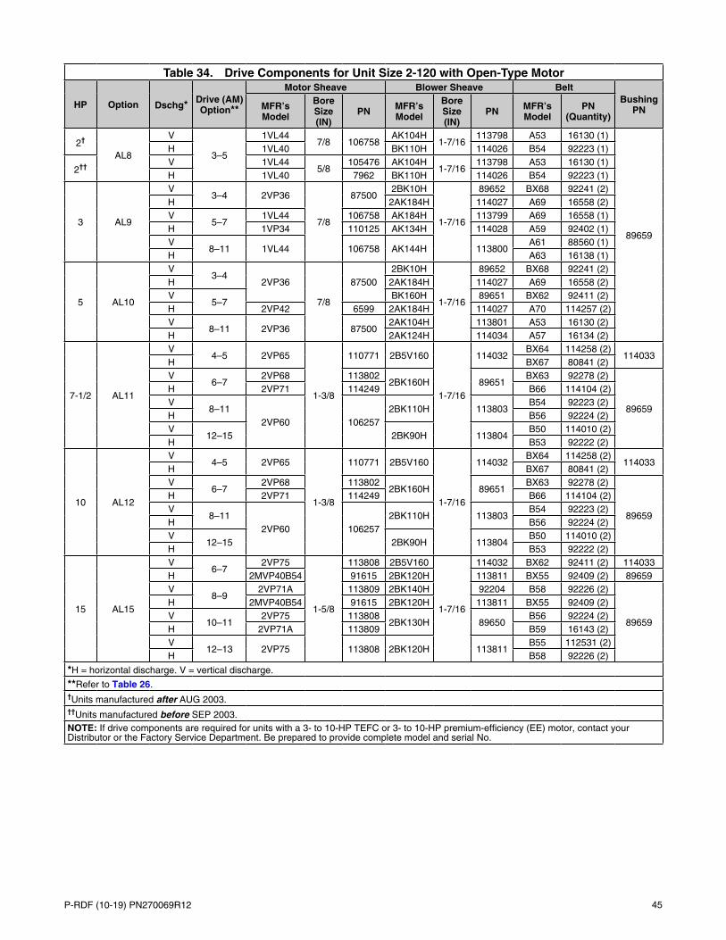
P-RDF (10-19) PN270069R12 45
Table 34. Drive Components for Unit Size 2-120 with Open-Type Motor
HP Option Dschg* Drive (AM) Option**
Motor Sheave Blower Sheave BeltBushing
PNMFR’s Model
Bore Size (IN)
PN MFR’s Model
Bore Size (IN)
PN MFR’s Model
PN (Quantity)
2†
AL8
V
3–5
1VL447/8 106758
AK104H1-7/16
113798 A53 16130 (1)
89659
H 1VL40 BK110H 114026 B54 92223 (1)
2†† V 1VL445/8
105476 AK104H1-7/16
113798 A53 16130 (1)H 1VL40 7962 BK110H 114026 B54 92223 (1)
3 AL9
V3–4 2VP36
7/8
875002BK10H
1-7/16
89652 BX68 92241 (2)H 2AK184H 114027 A69 16558 (2)V
5–71VL44 106758 AK184H 113799 A69 16558 (1)
H 1VP34 110125 AK134H 114028 A59 92402 (1)V
8–11 1VL44 106758 AK144H 113800A61 88560 (1)
H A63 16138 (1)
5 AL10
V3–4
2VP36
7/8
875002BK10H
1-7/16
89652 BX68 92241 (2)H 2AK184H 114027 A69 16558 (2)V
5–7BK160H 89651 BX62 92411 (2)
H 2VP42 6599 2AK184H 114027 A70 114257 (2)V
8–11 2VP36 875002AK104H 113801 A53 16130 (2)
H 2AK124H 114034 A57 16134 (2)
7-1/2 AL11
V4–5 2VP65
1-3/8
110771 2B5V160
1-7/16
114032BX64 114258 (2)
114033H BX67 80841 (2)V
6–72VP68 113802
2BK160H 89651BX63 92278 (2)
89659
H 2VP71 114249 B66 114104 (2)V
8–112VP60 106257
2BK110H 113803B54 92223 (2)
H B56 92224 (2)V
12–15 2BK90H 113804B50 114010 (2)
H B53 92222 (2)
10 AL12
V4–5 2VP65
1-3/8
110771 2B5V160
1-7/16
114032BX64 114258 (2)
114033H BX67 80841 (2)V
6–72VP68 113802
2BK160H 89651BX63 92278 (2)
89659
H 2VP71 114249 B66 114104 (2)V
8–112VP60 106257
2BK110H 113803B54 92223 (2)
H B56 92224 (2)V
12–15 2BK90H 113804B50 114010 (2)
H B53 92222 (2)
15 AL15
V6–7
2VP75
1-5/8
113808 2B5V160
1-7/16
114032 BX62 92411 (2) 114033H 2MVP40B54 91615 2BK120H 113811 BX55 92409 (2) 89659V
8–92VP71A 113809 2BK140H 92204 B58 92226 (2)
89659
H 2MVP40B54 91615 2BK120H 113811 BX55 92409 (2)V
10–112VP75 113808
2BK130H 89650B56 92224 (2)
H 2VP71A 113809 B59 16143 (2)V
12–13 2VP75 113808 2BK120H 113811B55 112531 (2)
H B58 92226 (2)
*H = horizontal discharge. V = vertical discharge.
**Refer to Table 26.†Units manufactured after AUG 2003.††Units manufactured before SEP 2003.NOTE: If drive components are required for units with a 3- to 10-HP TEFC or 3- to 10-HP premium-efficiency (EE) motor, contact your Distributor or the Factory Service Department. Be prepared to provide complete model and serial No.

46 P-RDF (10-19) PN270069R12
DRIVE COMPONENTS—CONTINUED
Table 35. Drive Components for Unit Size 3-180 with Open-Type Motor
HP Option Dschg*Drive (AM)
Option**
Motor Sheave Blower Sheave BeltBushing
PNMFR’s Model
Bore Size (IN)
PN MFR’s Model
Bore Size (IN)
PN MFR’s Model
PN (Quantity)
Units with Class 1 Blower
5 AL10
V2–3 2VP42
7/86599 2B5V250
1-7/16115718
BX97 92319 (2)114033
H B92 92308 (2)V
4–5 2VP36 87500 2BK190H 89652B86 92312 (2)
89659H BX77 92341 (2)
7-1/2, 10
AL11, AL12
V1 2VP71
1-3/8
114249 2B5V250
1-7/16
115718BX99 115932 (2)
114033H BX93 92313 (2)V
2 2VP60 106257 2BK190H 89652B88 115933 (2)
89659H BX79 92322 (2)V
3 2VP62 16150 2BK190H 89652B89 115934 (2)
89659H BX79 92322 (2)V
4–5 2VP65 110771 2B5V160 114032B84 92273 (2)
114033H BX75 92277 (2)V
6–7 2VP71 1142492B5V160 114032 BX85 92317 (2) 114033
H 2BK160H 89651 BX75 92277 (2) 89659V
8–9 2VP60 106257 2BK120H 113811BX75 92277 (2)
89659H BX66 92240 (2)
15, 20
AL15, AL16
V4–5 3MVP40B54
1-5/8
89644 3B5V136
1-7/16
115720BX77
92341 (3) 114033H BX68V
6–7 3MVP50B64 115719 3B5V154 115721BX81 92274 (3)
114033H B73 92230 (3)V
8–10 3MVP45B59 89645 3BK120H 115722B74 92231 (3)
89659H B65 6010 (3)V
11–14 3MVP40B54 89644 3BK90H 115723BX68 92241 (3)
89659H B59 16143 (3)
Units with Class 2 Blower
15, 20
AL15, AL16
V2–3 3MVP45B59
1-5/8
89645 3B5V184
2-3/16
115943B87 92310 (3)
116205
H B78 92234 (3)V
4–6 3MVP40B54 89644 3B5V136 115720BX77
92341 (3)H BX68V
7–9 3MVP40B54 89644 3B5V110 115935B73 92230 (3)
H BX64 114258 (3)V
10–12 3MVP50B64 115719 3B5V110 115935BX75 92277 (3)
H BX65 92276 (3)V
13–15 3MVP45B59 89645 3B6V90 115945BX71 92243 (3)
H BX62 92411 (3)
25 and 30
AL17, AL18
V5–6 4MVP50B64
1-7/8
115931 4MVB154R
2-3/16
116204BX80 92412 (4)
116206
H BX71 92243 (4)V
7–9 4MVP45B59 115946 4MVB124R 116203BX72 92277 (4)
H BX65 92276 (4)V
10–12 4MVP50B64 115931 4MVB110R 116202B73 92230 (4)
H BX63 92278 (4)V
13–16 4MVP50B64 115931 4MVB94Q116202 BX63 92278 (4)
H 116201 BX61 92289 (4) 116207
*H = horizontal discharge. V = vertical discharge.
**Refer to Table 26.NOTE: If drive components are required for units with a 5- to 15-HP TEFC or 5- to 15-HP premium-efficiency (EE) motor, contact your Distributor or the Factory Service Department. Be prepared to provide complete model and serial No.

P-RDF (10-19) PN270069R12 47
Table 36. Drive Components for Unit Size 3-260 with Open-Type Motor
HP Option Dschg*Drive (AM)
Option**
Motor Sheave Blower Sheave BeltBushing
PNMFR’s Model
Bore Size (IN)
PN MFR’s Model
Bore Size (IN)
PN MFR’s Model
PN (Quantity)
Units with Class 1 Blower
7-1/2, 10
AL11, AL12
HA3 2MVP35B49
1-3/8
115940 2B5V234
1-11/16
115941BX103 92316 (2)
115949
V BX113 115947 (2)H
A4 2VP60 106257 2B5V234 115941BX103 92316 (2)
V BX115 115948 (2)H
1–2 2MVP40B54 89641 2B5V184 115942BX93 92313 (2)
V BX105 92314 (2)H
3–4 2VP60 106257 2B5V160 114032BX90 92315 (2)
V BX103 92316 (2)
15, 20
AL15, AL16
HA4 3MVP40B54
1-5/8
89644 3B5V234
1-11/16
115944BX100 92318 (3)
V BX113 115947 (3)H
1 3MVP50B64 115719 3B5V234 115944B101 115865 (3)
V BX113 115947 (3)H
23MVP40B54
89644 3B5V184 115943BX90 92315 (3)
V BX103 92316 (3)H
3–5 89644 3B5V154 115721B84 92273 (3)
V BX97 92319 (3)Units with Class 2 Blower
15, 20
AL15, AL16
HA4 3MVP45B59
1-5/8
89645 3MVB250R
2-11/16
116446BX103 92316 (3)
116451V BX115 115948 (3)H
1 3MVP40B54 89644 3MVB200R 116447BX93 92313 (3)
V BX105 92314 (3)H
2–3 3MVP45B59 89645 3MVB184Q 116448BX90 92315 (3)
91609V BX103 92316 (3)H
4–6 3MVP40B54 89644 3MVB136Q 116449BX81 92274 (3)
V B94 119610 (3)
25, 30
AL17, AL18
H1 4MVP50B69
1-7/8
116460 4MVB250R
2-11/16
116461BX103 92316 (4)
116451
V BX115 115948 (4)H
2–3 4MVP45B59 115946 4MVB184R 116462BX90 92315 (4)
V BX103 92316 (4)H
4–5 4MVP45B59 115946 4MVB154R 116204BX83 92333 (4)
V BX96 92334 (4)H
6–8 4MVP55B69 116460 4MVB154R 116204BX85 92317 (4)
H BX97 92319 (4)
*H = horizontal discharge. V = vertical discharge.
**Refer to Table 26.NOTE: If drive components are required for units with a 7-1/2- to 20-HP TEFC or 7-1/2- to 20-HP premium-efficiency (EE) motor, contact your Distributor or the Factory Service Department. Be prepared to provide complete model and serial No.
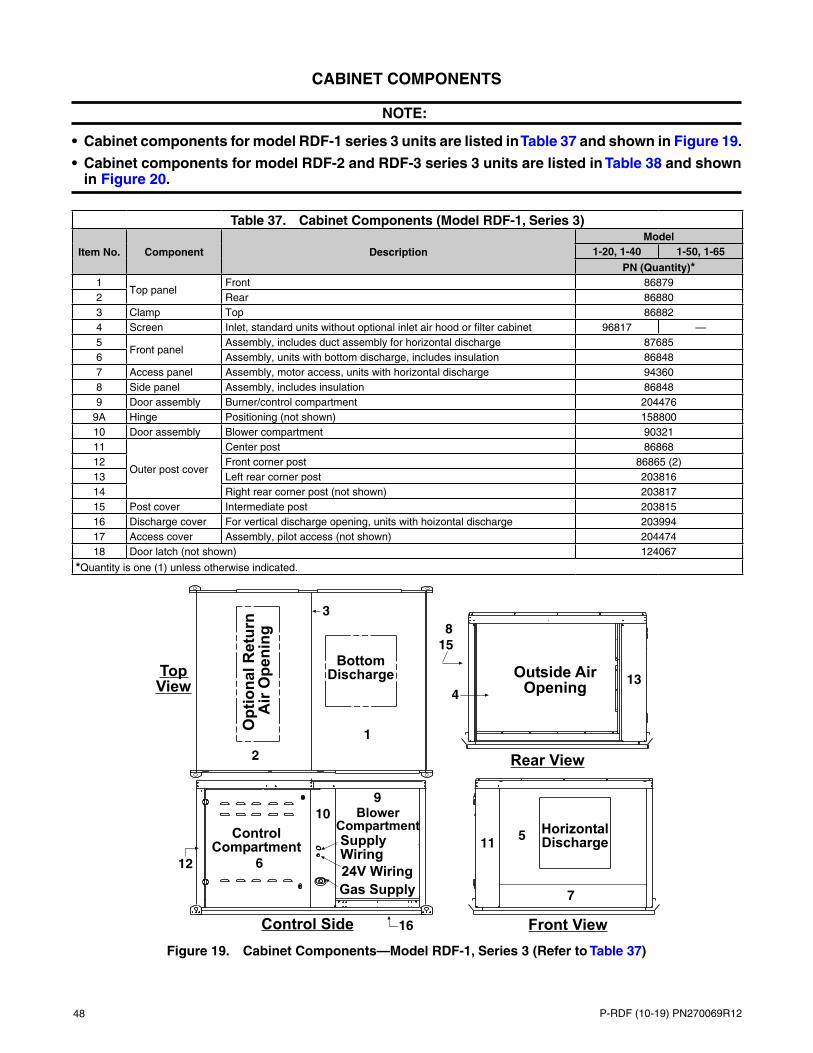
48 P-RDF (10-19) PN270069R12
CABINET COMPONENTS
NOTE:
• Cabinet components for model RDF-1 series 3 units are listed in Table 37 and shown in Figure 19.
• Cabinet components for model RDF-2 and RDF-3 series 3 units are listed in Table 38 and shown in Figure 20.
Table 37. Cabinet Components (Model RDF-1, Series 3)
Item No. Component DescriptionModel
1-20, 1-40 1-50, 1-65
PN (Quantity)*1
Top panelFront 86879
2 Rear 868803 Clamp Top 868824 Screen Inlet, standard units without optional inlet air hood or filter cabinet 96817 —5
Front panelAssembly, includes duct assembly for horizontal discharge 87685
6 Assembly, units with bottom discharge, includes insulation 868487 Access panel Assembly, motor access, units with horizontal discharge 943608 Side panel Assembly, includes insulation 868489 Door assembly Burner/control compartment 204476
9A Hinge Positioning (not shown) 15880010 Door assembly Blower compartment 9032111
Outer post cover
Center post 8686812 Front corner post 86865 (2)13 Left rear corner post 20381614 Right rear corner post (not shown) 20381715 Post cover Intermediate post 20381516 Discharge cover For vertical discharge opening, units with hoizontal discharge 20399417 Access cover Assembly, pilot access (not shown) 20447418 Door latch (not shown) 124067
*Quantity is one (1) unless otherwise indicated.
4
6
5
3
910
11
2
7
12
13
1
815
16
Figure 19. Cabinet Components—Model RDF-1, Series 3 (Refer to Table 37)

P-RDF (10-19) PN270069R12 49
Table 38. Cabinet Components (Models RDF-2 and RDF-3, Series 3)
Item No. Component DescriptionModel
2-80 2-120 3-180, 3-260
PN (Quantity)*1
Top panelFront 89558 91172
2 Center — 911733 Rear 89559 911744 Clamp Top 89562 91179 (2)5
Door assembly
Right rear side 203745 2045586 Side 89510 (2) 91116 (3)7 Front burner/control compartment 204498 2045598 Rear burner/control compartment 204497 204560
8A Hinge Positioning 1588009
Front panelAssembly, includes duct assembly for horizontal discharge 89519 91125
10 Assembly, units with bottom discharge (not shown) 89967 9121211
Outer post cover
Left front corner post 89547 9115712 Right front corner post 89547 9115813 Intermediate post #1 89552 20453614 Intermediate post #2 — 91163 (2)15 Left rear corner post 203728 20364616 Right rear corner post 203736 20364417 Intermediate post Control 203729 20363918 Discharge cover For vertical discharge opening, units with hoizontal discharge 203982 204707 20453819 Access cover Assembly, pilot access (not shown) 204474 20387620 Door latch (not shown) 124067
*Quantity is one (1) unless otherwise indicated.
13 2
6
5
4
9
11
12
14
15
18
1713
78
16
6614
Figure 20. Cabinet Components—Models RDF-2 and RDF-3, Series 3 (Refer to Table 38)

50 P-RDF (10-19) PN270069R12
SCREENED AIR INLET HOODS FOR OUTDOOR UNITS
NOTE:
• Screened air inlet hood option packages for outdoor units are listed in Table 39.
• Option package components are listed in Table 40.
Table 39. Screened Air Inlet Hood Option Packages for Outdoor Units
Option Package Description OptionModel
RDF-1 RDF-2 RDF-3Package PN
100% outside air inlet hood AS2 69594 68774 71150100% outside air inlet hood with integral filter rack and 1-inch permanent filters AS6 69596 68739 71152100% outside air inlet hood with integral filter rack and 2-inch permanent filters AS7 72623 72625 72627
Table 40. Screened Air Inlet Hood Option Package Components
Model Component DescriptionOption Package PN (Option*)
69594 (AS2) 69596 (AS6) 72623 (AS7)
Component PN (Quantity)**
RDF-1
Hood panel
Top 87520 — —Bottom 87530 87530 87530Left side 87522 87522 87522Right side 87523 — —
Weather hood Top — 87520 87520Hood corner Right — 87531 87531
LouverLeft side 87525 87525 87525Right side 87526 87526 87526
— 87527 (11) 87527 (11) 87527 (11)Screen 39 × 35-1/4 inches 87528 87528 87528Angle Screen 87529 (2) 87529 (2) 87529 (2)Door Filter — 87538 87538Filter adapter Side — 87521 87521
Filter channelTop/bottom assembly — 87532 (2) 94220 (2)Top/bottom — 87533 (2) —Top/bottom, 2-inch — — 94137 (2)
Filter angle Right side — 87534 87534Filter support Right side — 87535 87535
Block-off plateTop filter 87536 87536Bottom filter — 87537 —
Screw Sheet metal, #10-16 × 1/2 11813 (34) 11813 (54) 11813 (54)
Permanent filter12 × 35 × 1, aluminum — 87251 (3) —12 × 35 × 2, aluminum — — 94383 (3)
*Refer to Table 39.
**Quantity is one (1) unless otherwise indicated.

P-RDF (10-19) PN270069R12 51
Table 40. Screened Air Inlet Hood Option Package Components
Model Component DescriptionOption Package PN (Option*)
68774 (AS2) 68739 (AS6) 72625 (AS7)
Component PN (Quantity)**
RDF-2
Hood panelBottom 89972 89972 89972Top, front 90220 90220 90220Top, rear 90221 90221 90221
Clamp Top 90222 90222 90222
CornerLeft 95279 95279 95279Right 89981 89981 89981
LouverLeft side 89975 89975 89975Right side 89976 89976 89976
— 89977 (14) 89977 (14) 89977 (14)Screen 89978 89978 89978Angle Screen 89979 89979 89979Door Filter 89988 (2) 89988 (2) 89988 (2)
Filter adapterLeft 95280 95280 95280Right 89980 89980 89980
Filter channelTop/bottom assembly — 89982 (3) 94221 (3)Top/bottom — 89983 (2) —Top/bottom, 2-inch — — 94222 (2)
Block-off plateTop filter — 89986 89986Bottom filter — 258249 258249
Support 91581 (6) 91581 (6) 91581 (6)Nut Hex, Keps, 1/4-20 7328 (6) 7328 (9) 7328 (6)
ScrewSheet metal, #10-16 × 1/2 11813 (44) 11813 (64) 11813 (64)Hex head, slotted, #14-10 × 3/4 41463 (3) 41463 (3) —Hex head, slotted, 1/4-20 × 5/8 10393 (6) 10393 (9) 10393 (6)
Permanent filter
12 × 35 × 1, aluminum — 87251 (4) —12 × 24 × 1, aluminum — 89353 (4) —12 × 24 × 2, aluminum — — 94382 (4)12 × 35 × 2, aluminum — — 94383 (4)
*Refer to Table 39.
**Quantity is one (1) unless otherwise indicated.
—Continued

52 P-RDF (10-19) PN270069R12
Table 40. Screened Air Inlet Hood Option Package Components
Model Component DescriptionOption Package PN (Option*)
71150 (AS2) 71152 (AS6) 72627 (AS7)
Component PN (Quantity)**
RDF-3
Hood panel
Top front 91575 91575 91575Top rear 91576 91576 91576Bottom 91567 91567 91567Left side 91568 91568 91568Right side 91569 91569 91569
Clamp Top 91577 91577 91577Corner Left/right 91579 (2) 91579 (2) 91579 (2)Louver rack Assembly 113003 (2) 113003 (2) 113003 (2)Door Filter 91585 (2) 91585 (2) 91585 (2)
Filter channel
Top/bottom assembly — 91586 (5) —Top/bottom assembly, 2-inch — — 94223 (5)Top/bottom — 91580 (2) —Top/bottom, 2-inch — — 94224 (2)
Block-off plateFilter — 263784 (6) 263784 (5)Bottom filter — — 98764 (2)
— — 91584 (2) —Filter support Right side 272444 (2) 272444 (2) 272444 (2)Support 91581 (6) 91581 (6) 91581 (6)Post Intermediate 91578 (2) 91578 (2) 91578 (2)
NutHex, Keps, 1/4-20 7328 (15) 7328 (15) 7328 (15)#C7392-110z-1 — 1849 (5) 1849 (5)
Palnut #Pw-1880-008-21 87900 (5) — —
Screw
Sheet metal, #10-16 × 1/2 11813 (100) 11813 (100) 11813 (100)Hex head, slotted, #14-10 × 3/4 41463 (3) 41463 (3) 41463 (3)Teks, #10-16 × 1/2, S/drill 37661 (4) 37661 (4) 37661 (4)Hex head, slotted, 1/4-20 × 5/8 10393 (15) 10393 (15) 10393 (15)
Permanent filter12 × 35 × 1, aluminum — 87251 (12) —12 × 35 × 2, aluminum — — 94383 (10)
*Refer to Table 39.
**Quantity is one (1) unless otherwise indicated.
SCREENED AIR INLET HOODS FOR OUTDOOR UNITS—CONTINUED
—Continued

P-RDF (10-19) PN270069R12 53
OUTSIDE AIR FILTER RACK ASSEMBLIES FOR INDOOR UNITS
NOTE:
• Outside air filter rack assemblies for indoor units are listed in Table 41.
• Option package components are listed in Table 42.
Table 41. Outside Air Filter Rack Assembly Option Packages for Indoor Units
Option Package Description OptionModel
RDF-1 RDF-2 RDF-3Package PN
Outside air filter section for indoor units with 1-inch filters AW3 69597 68775 71153Outside air filter section for indoor units with 2-inch filters AW6 72624 72626 72628
Table 42. Outside Air Filter Rack Assembly Option Package Components
Component Description
ModelRDF-1 RDF-2 RDF-3
Option Package PN (Option*)69597 (AW3)
72624 (AW6)
68775 (AW3)
72626 (AW6)
71153 (AW3)
72628 (AW6)
Component PN (Quantity)**
Filter cabinet panelTop 87862 89992 91590Bottom 87861 89991 —
Filter cabinet cornerLeft/right rear — — 91587 (2)Right rear 87859 (2) 89989 (2) —Right 87860 (2) 89990 (2) —
Duct angle Filter cabinet — — — 91583Hood corner Left/right — — 91579 (2)Hood panel Bottom — — 91567Door Filter 87538 (2) 89988 (2) 91585 (2) 91585 (2)
Filter channel
Top/bottom assembly 87532 (2) 94220 (2) 89982 (3) 94221 (3) 91586 (5) —Top/bottom assembly, 2-inch — — — 94223 (4)Top/bottom 87533 (2) — 89983 (2) — 91580 (2) 94224 (2)Top/bottom, 2-inch — 94137 (2) — 94222 (2) —
Block-off plate
Top filter — 87536 89986 —Bottom filter — 258249 — 98764 (2)Filter — 114335 (4) 114336 (4) 263784 (6) 263784 (5)
— — — 91584 (2) —Screw Sheet metal, #10-16 × 1/2 11813 (44) 11813 (54) 11813 (64) 11813 (50)
Permanent filter
12 × 35 × 1, aluminum 87251 (3) — 87251 (4) — 87251 (12) —12 × 24 × 1, aluminum — 89353 (4) — —12 × 24 × 2, aluminum — — 94382 (4) —12 × 35 × 2, aluminum — 94383 (3) — 94383 (4) — 94383 (10)
*Refer to Table 41.
*Quantity is one (1) unless otherwise indicated.

54 P-RDF (10-19) PN270069R12
ROOF CURB COMPONENTS
NOTE:
• Each roof curb package (option CJ3) for a model RDF system includes two curb sides, one front, one back, eight curb dividers for creating supply and return air ductwork in the curb, and hardware for corner assembly and for installing ductwork dividers.
• IMPORTANT: The area enclosed by the roof curb must comply with clearance to combustible materials. If the roof is constructed of combustible materials, the area within the roof curb must be ventilated, left open, or covered with non-combustible material that has an R-value of at least 5. If the area within the curb is left open, higher radiated sound levels may result.
• Roof curb components are listed in Table 43, dimensions are listed in Table 44, and components and dimensions are shown in Figure 21. The 3/4-inch (19-mm) measurement is the width of the flanges where the roof curb mates with the heater. These flange surfaces must be sealed.
• When cutting duct openings in the roof, cut the opening 1 inch (25 mm) larger than the duct size opening for installation clearance.
Table 43. Roof Curb Components
Item No.* Component Description
Series 3 ModelRDF-1 RDF-2 RDF-3
Option CJ3 Package PN204368 203980 204370
Component PN (Quantity)1
CurbFront and back assembly 104655 (2) 111508 (2) 111512 (2)
2 Side assembly 204365 (2) 204366 (2) 204369 (2)3
Curb divider Ductwork203803 (4) 203977 (4) 203662 (4)
4 203804 (2) 203978 (2) 203663 (2)5 203806 (2) 203979 (2) 203664 (2)
Roof Curb Corner Hardware
—
Lockwasher5/16, for top two holes 1333 (8)5/16, for bottom two holes 1333 (8)
Lag screw 5/16 × 1, for top two holes 16243 (8)Hex head capscrew 5/16 × 3/4, for bottom two holes 16247 (8)Hex nut 5/16-18, for bottom two holes 1035 (8)
Hardware for Divider Assembly and Attachment (to Make Duct Openings)— Screw Sheet metal, #10-16 × 1/2 11813 (64)
*See Figure 21.
Table 44. Roof Curb Dimensions
Letter Code*Series 3 Model
RDF-1 RDF-2 RDF-3Inches (mm)
Curb DimensionsA 84-5/8 (2149) 84-5/8 (2149) 131-3/4 (3346)B 43-5/8 (1108) 67-9/16 (1716) 82-1/16 (2084)
C** 80-7/8 (2054) 80-7/8 (2054) 128 (3251)
D** 39-7/8 (1013) 63-13/16 (1621) 78-5/16 (1989)
Duct Opening DimensionsE 23-11/32 (593) 28-13/32 (722)
38 (965)F 20-1/8 (511) 28-11/32 (720)G 5 (127) 13-15/32 (342) 11-19/32 (294)H 10-1/4 (260) 7 (178) 4-5/8 (117)J 25-1/2 (648) 54-11/16 (1389) 66-3/4 (1695)K 11-1/2 (292) 17-23/32 (432) 20-1/16 (510)M 11-15/32 (291) 8 (203) 10-15/32 (266)N 11-1/32 (280) 11-3/32 (282) 17-1/4 (438)
*See Figure 21.
**Roof opening dimensions if curb area is fully open.
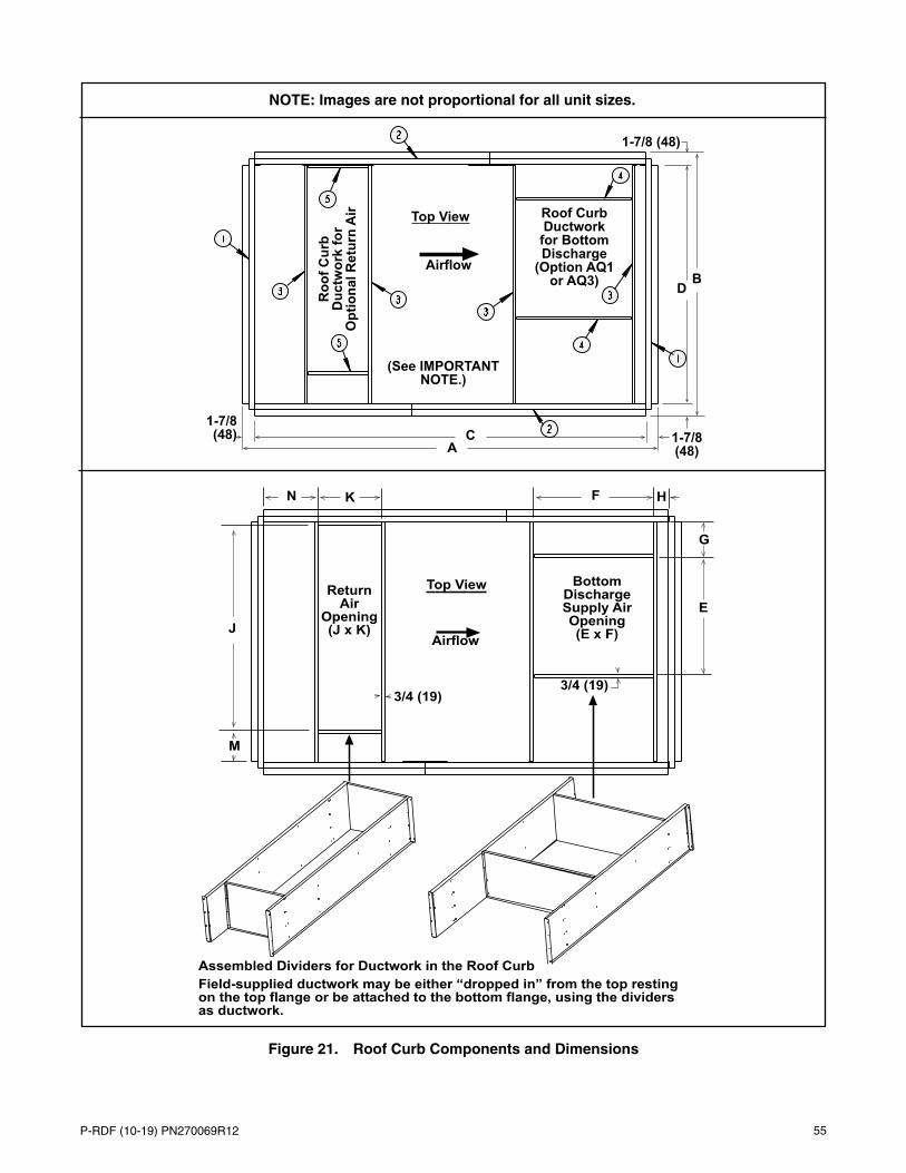
P-RDF (10-19) PN270069R12 55
Figure 21. Roof Curb Components and Dimensions
NOTE: Images are not proportional for all unit sizes.

Specifications and illustrations subject to change without notice or incurring obligations.©2019 Nortek Global HVAC LLC, O’Fallon, MO.All rights reserved.P-RDF (10-19) PN270069R12
AG
ENCY PROCESS
STA
RT-
UP
PRODUCT
CU
STOM
ER
WARRANTY
CONVERGENT
QUALITY SYSTEM
CQSQ M
CQS