repairing the coin control relay - telephone...
TRANSCRIPT

Coin Trigger Lever~~ ~~
Coin Trigger Armature Pivot FrameCoin Trigger Pin ~~~'L (shown cut away)
P-248039 .Outer GroundArmature Siop--~~~~~,~f~lI Contact Spring
Resto~l':i~t'i\.~;l·-"""fo;~o Insulating RollerArmature Dial Shunt Spring
Restoring~ Coin TriggerSpring Brackec/ (' t mll: Lever Spring
Armature I I ' Inner GroundRestorlng' Contact Spring
Springs IV<:::l..lJ----......1l",...'
Fig. 1 Two-coil prepay coin control relay. Fig. 2 Single-coil relay.
Repairing the coin control relay
Chapter 15 of this series digs into the details ofa vital area of paystation instrument repair
Melvin E. Hacker
THE LAST ARTICLE in thisseries gave a quick rundown oncoin telephones and their repair.Now we get down to an in-depthreview of coin control relaymaintenance and allied repairoperations on coin telephoneswithin the repair center. Emphasis will be placed on the"care and feeding" of prepaycoin telephone equipment sincemost paystation instruments areof this type.
Two different types of coincontrol relays (Figures 1 and 2)are used on prepay sets. Thetwo-coil type coin control relaywhich has been in use for 55years, recently has been superseded by a newly developedsingle-coil variety. -The new relay, in association with a redesigned hopper assembly, offers
©MELVIN E. HACKER, 1969. Mr.Hacker is customer equipment engineer for GT&E Service Corp., NewYork City. Chapter 1 of this seriesappeared in the March 23, 1968,issw8 of TELEPHONY.
28
greater coin capacity and reduced field maintenance, as wellas the ability to operate efficiently over longer subscriberloops than its predecessor.
Where the older hopper couldaccept a maximum of 11 quarters, the single-coil hopper is designed to hold 20 quarters without jamming. This latter featureis of great value in reducing thelost operating time involved inmultiple collections for long distance calls. The new $5 capacityeffectively reduces the number ofcollections required for each tollcall that would have exceeded thecapacity of the older hopper.However, only a relatively smallnumber of the single-coil relaysare in use now, so this articlewill be devoted to the requirements of the two-coil variety.Those interested in learningmore about the single-coil relaymay refer to the January, 1968,issue of the "Automatic ElectricTechnical Journal" for a comprehensive technical description
of its development and operation.
Two-coil coin control relay
Generalr-The two-coil prepaycoin relay (See Figure 1) is anelectro-mechanical device thatserves a number of purposes.While its primary function is toprovide a means of collectingand refunding deposited coins,the relay also .satisfies other important circuit control requirements.
In the prepay coin telephonesystem, central office equipmentand the telephone set are teamedup to enforce coin deposit beforetelephone calls are permitted.,This minimizes fraudulent use ofthe paystation. For example, although dial tone may be obtained merely by lifting the prepay coin telephone handset (Automatic Electric Co. equipment)it is impossible to dial a numberdue to the absence of the groundnecessary to permit dialing.(The required ground is pro-
TELEPHONY
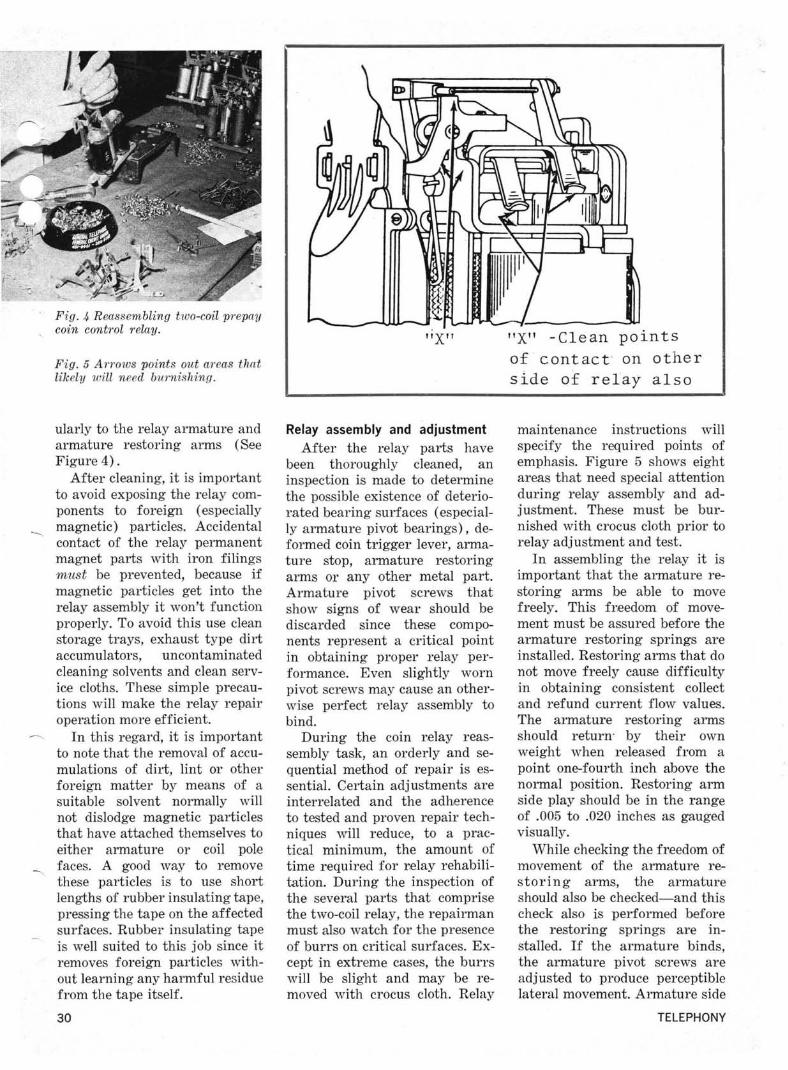
Fig. 4 Reassembling two-coil prepaycoin control relay.
Fig. 5 An'ows points out areas thatlikely will need burnishing.
ularly to the relay armature andarmature restoring arms (SeeFigure 4).
After cleaning, it is importantto avoid exposing the relay components to foreign (especiallymagnetic) particles. Accidental-...contact of the relay permanentmagnet parts with iron filingsmust be prevented, because ifmagnetic particles get into therelay assembly it won't functionproperly. To avoid this use cleanstorage trays, exhaust type dirtaccumulators, uncontaminatedcleaning solvents and clean servic.e cloths. These simple precautions will make the relay repairoperation more efficient.
In this regard, it is importantto note that the removal of accumulations of dirt, lint or otherforeign matter by means of asuitable solvent normally willnot dislodge magnetic particlesthat have attached themselves toeither armature or coil pol.e
--... faces. A good way to removethese particles is to use shortlengths of rubber insulating tape,pressing the tape on the affectedsurfaces. Rubber insulating tapeis well suited to this job since itremoves foreign particles without learning any harmful residuefrom the tape itself.
30
"X"
Relay assembly and adjustment
After the relay parts havebeen thoroughly cleaned, aninspection is made to determinethe possible existence of deteriorated bearing surfaces (especially armature pivot bearings), deformed coin trigger lever, armature stop, armature restoringarms or any other metal part.Armature pivot screws thatshow signs of wear should bediscarded since these components represent a critical pointin obtaining proper relay performance. Even slightly wornpivot screws may cause an otherwise perfect relay assembly tobind.
During the coin r,elay reassembly task, an orderly and sequential method of repair is essential. Certain adj ustments areinterrelated and the adh.erenceto tested and proven repair techniques will reduce, to a practical minimum, the amount oftime required for r,elay rehabilitation. During the inspection ofthe several parts that comprisethe two-coil relay, the repairmanmust also watch for the presenceof burrs on critical surfaces. Except in extreme cases, the burrswill be slight and may be removed with crocus cloth. Relay
"X" -Clean pointsof contact on otherside o~ relay also
maintenance instructions willspecify the required points ofemphasis. Figure 5 shows eightareas that need special attentionduring relay assembly and adjustment. Th.ese must be burnished with crocus cloth prior torelay adj ustment and test.
In assembling the relay it isimportant that the armature restoring arms be able to movefreely. This freedom of movement must be assured before thearmature restoring springs areinstalled. Restoring arms that donot move freely cause difficultyin obtaining consistent collectand refund current flow values.The armature restoring armsshould return' by their ownweight when rel.eased from apoint one-fourth inch above thenormal position. Restoring armside play should be in the rangeof .005 to .020 inches as gaugedvisually.
While checking the freedom ofmovement of the armature restoring arms, the armatureshould also be checked-and thischeck also is performed beforethe restoring springs are installed. If the armature binds,the armature pivot screws areadjusted to produce perc.eptiblelateral movement. Armature side
TELEPHONY

vided by the coin control relaywhen a coin is deposited.) Further, even if a fraudulent groundis somehow applied, dialing stillcannot be achieved without coindeposit because the coin controlrelay maintains a shunt acrossthe dial impulse contacts. Thus, itis evident that the prepay coincontrol relay is critical to thesatisfactory performance of thecoin telephone instrument.
Theory of Operation-Thetwo-coil coin control relay is ofthe polar type, that is, the combination of its permanent magnetic elements and its two electromagnetic coils imparts to themechanism a bi-directional operating capability. This is essentialbecause the prepay coin telephonemust be able to collect as well asrefund deposited coins undercontrol of associated central office equipment. With coins deposited in the hopper, a -110volt dc potential applied to thetip conductor of the telephoneline will cause a properly adjustedrelay to operate in the refundmode, while the application of+110 volt dc to the tip conductor will initiate a collect relaycycle.
Although it is only necessaryto apply the relay control potential to the tip conductor of thetelephone line, in actual practicemost central office repay paystation repeaters connect the control potential to tip and ring conductors simultaneously. This feature is used to advantage in thelong loop operation of coin control relays inasmuch as an additional relay within the paystation instrument operates duringthe collect/refund interval toalso short the T and R conductors at the station; with the loopthus shorted at each end, itseffective resistance is halved andthereby permits increased relaycontrol current to flow. Increased current flow, of course,results in improved operationalreliability.
The reliability with whichthese functions are performed isin part related to the degree ofprecision and care eXJercised byrepair personnel in the maintenance of the coin relay itself. Arelated factor, of course, is inthe level of maintenance appliedto central office paystation repeaters and associated equipment.
Tools for the job
Maintenance of the two-coilrelay, and indeed all coin controlrelays, requires the use of precision tools. Heavy duty springbender, small screwdriver,inspection mirror, burnishingtool, set of thickness gauges, crocus cloth, gram gauge (see Figure 3), light duty spring bender,duckbill pliers and special feelergauges are some of the itemsrequired.
The number and types of toolswill be identified in the appropriate shop proce9ure devoted tothe repair of coin control relays,and personal copies of this aswell as other paystation repairinstructions should be maintained by each of the employesassigned to the paystation repairsection.
Clean it, keep it clean
All prepay coin control relaysthat have been returned fromfield service should be completely dismantled and thoroughly
:cleaned. Ideally, the disassem-bled relay parts should be reassembled in their original operating positions; this applies partic-
Fig. 3 Checking operating gram tension of coin trigger.
JUNE 14, 1969 29

~
r OPERATING ARM _-+--".~~:~:~~~~ STOP LUG
ARMATURERESTORING ARM
-Fig_ 7 Adjusting coin relay operating arm stop lug forproper clearance.
Operating Arm Stop Lug
Pivot Frame~::::::::~
Fig. 8 Using gauge and screw-driver to check and adjustarmature operating travel.
~nt as required to obtain the- luired clearance.'" "When mounted within an in
.. __l'ument, the relay operatingarm fork must bring the coinvane to a vertical position suchthat it may be seen through thecenter hole of the coin trap; thisadjustment may be met by sliding the relay assembly right orleft, as required. When the coinrelay is installed in a paystationinstrument, the positioning ofthe vane at the mid-point of the~nter hole of the coin trap is
:tically important. The displacement of the coin vane evenslightly to either side, gives thecoin relay a mechanical biaswhenever coins are deposited.This can produce the same typeof malfunction as is produced byimproper adjustment of theclearance between the core facesand the armature restoringarms. Thus, it is apparent that amultiplicity of adjustments af-~ts the two-coil coin relay as~_mbly and that optimum performance is obtained only by ob
;serving each individual requirement, and assuring that properlimits are satisfied.~ In addition to these, there areother mechanical adjustments
):h,at are equally important to the,isfactory disposal of deposit
ed coins. For example, the relayarmature is required to operate
;lectrical contacts to permit amber to be dialed as well as to
establish a circuit for the ultimate disposal of deposited coins.Adjustment of the coin trigger
32
and its related switch lever combine to assure that these requirements are met. Checks must alsobe made to ascertain that properclearance conditions exist between the trigger lever and theoperating arm and that thespring tension present in thecontact assembly is within therange necessary to permit proper operation under the conditionof a single 10-cent deposit. Thecoin trigger must be free ofbinds about its bearing pin andpossess a side play of .005 inchesas gauged by eye.
When installed in a coin telephone set, the coin trigger musttrip under a maximum load of 5grams applied midway betweenthe hopper and the coin relayassembly. With the coin triggerin a tripped condition, graduallylifting the switch lever from thetrigger cam should cause thetrigger to restore to normal.With the coin trigger trippedand the operating arm operatedto the refund position, the cointrigger lever is adj usted to permit the trigger to restore with a.015 inch gauge under the operated stop lug and not restorewith a .030 inch gauge under thelug. This test is repeated on thecollect side and the adjustmentof this tolerance is illustrated inFigure 8.
It was stated earlier that thecoin relay contains switching elements to enforce coin deposit aswell as provide an operatingpath for the relay itself. Thesecontacts are normally adjusted
in connection with the establishment of coin trigger operatingparameters. The mechanical positioning of the contacts, the application of required spring tension (under both normal andtripped coin trigger conditions)and the movement of the nylonroller that actuates the contactsmust be attended to. To avoidupsetting the mechanical balanceof the relay assembly, the manufacturer's adjustment specifications must be strictly followed.
Relay test and final adjustment
While the two-coil coin relaymay be brought to a close approximation of its optimum operating point by adjustments applied outside the telephone set, itis important to note that finaladjustments should be appliedwhile the relay is mounted within a paystation instrument. Ithas been found that the magnetic flux established by the currentflowing through the relay coils isdisturbed by the metallic structure of the paystation upperhousing. For this reason, a relaythat appears to function properly with the upper housing remov,ed may fail to refund or collect with the upper housing inplace.
The final adjustment of thecoin relay requires the provisionof a rather simple piece of testapparatus. Supplied by a suitable power source of stable directcurrent, the test set must be capable of applying the required operate, non-operate and release
TELEPHONY

play of a properly adjusted relaywill fall in the range of .002 to.005 inches.
After these checks, the armature restoring springs are installed. A check is then made todetermine that the armaturespacing between the respectivecoil pole face:;> is within limits.The gaps between the armatureends and the collect and refundcores should be equal as gaugedvisually. At the same time, theend of the armature should lineup with the respective cores. Minor deviations may be correctedby loosening the two smallscrews on top of the armaturebearing saddle and turning thecenter cam screw in the properdirection. Be sure to retightenthe two small lock screws aftermaking this adjustment. If thearmature cannot be satisfactorily repositioned as just described,it will be necessary to replaceeither the armature or coil polepieces.
With the proper armature-tocoil core spacing established, acheck is made to determine thatthe armature lines up with thecores. Armature alignment errors are corrected by looseningthe locking nuts on the armaturepivot screws and simultaneouslyadjusting front and rear pivotsto move the armature in the required direction. When makingthis adjustment, the properamount of armature side playmust be maintained as discussedearlier in this article.
With the armature properlypositioned within the relayframe, a series of checks andadj ustments is required to establish the conditions necessaryfor optimum coin relay performance. These include the adjustment of the gap between the armature and its stops on the operating arms and the adjustmentof the restoring arms and theirrelationship to the two corefaces. In the case of the former,the gap should be in the range of.007 to .020 inches as measuredindividually with all the play
JUNE 14, 1969
RESTORINGLEVER
CORE
a. PROPERLY AOJUSTEORESTORI NG LEVER
SPRING SENOER
b. METHOO OF AOJUSTMENT
Fig. 6 The clearance adjustment ishighly critical.
taken up from the opposite gap,while the latter adjustment specifies no clearance between therestoring arms and· coil coresand between the operating armsand restoring arms. (See Figure6). With respect to the clearancebetween operating arm and armature stop lug and the armature, the clearance should be in /the range of .010 to .020 incheswith all the play taken up fromthe opposite gap. This requirement is met by bending the armature stop as close as possibleto its point of contact.
Of all the adjustments thus 'far described, the no clearancerequirement shown in Figure 6is perhaps the most important.Lack of attention to this seemingly minor adjustment has beenthe cause of many coin relayfailures in the field. What happens is that money is collectedwhen it should have been refunded. Detailed analysis of therelays involved showed thatthere was clearance between thearmature restoring arm and therelay coil cores and, under the ->
influence of the mechanical biasof a coin load, imparted the necessary movement to make properrelay operation marginal. Thatis, under the indicated conditions, application of a refundsignal collected the depositedcoins instead of refunding them,because the mechanical andelectrical relationships of thecoin relay favored the undesiredmode of operation. This particu- ~
lar adjustment, as well as anoth-er to be described later concern-ing coin relay installation, deserves great emphasis during theapprenticeship phase of coin re-lay maintenance personnel.
Operating arm travel is nextdetermined by adjusting the operating arm stop lug as shown inFigure 7. In its normal position,the clearance should be from.125 to .133 inches. This adjustment establishes the proper dis- /placement of the coin vane in thecoin hopper under collect and refund conditions. The stop lug is
31

33
Study the manualAlthough this and the preced
ing article have explored in reasonabIe detail paystation equipment maintenance, these two articles are by no means intendedto supplant the existing manufacturer's adjustment instructions or repair shop procedureson this subject. Nevertheless theuninformed reader should, froma reading of the two articles,gain a better understanding ofthe problems confronting thosewho service not only the paystation instruments, but also thecoin relays. It should be evidentthat repair personnel assigned toservicing paystation equipmentrequire intensive training. Comprehensive training procedurestogether with supervised practical experience in cleaning, repairing and adj usting paystationsets will develop the technicalcompetence required to assurethe production of uniformly highquality telephone equipment bythe repair center. 0
(The next article in this serieswill cover the maintenance of key Itelephone sets and systems.)
event, the operate value of therelay must be retested.
A final electrical test verifiesthe release point of the coin relay. A current of 120 milliamperes is applied to the coin relayand then slowly reduced to 29.4milliamperes without an interruption; at 29.4 milliamperes,the armature must resto~e tonormal.
~Fig. 9 This test set used in final adjustment of the coin relay was constructed by a telephone repair center.
- .....
current values to the coin relay.At the same time, the test deviceis required to provide a soak current of opposite polarity to certain of the required tests. Figure9 illustrates a unit constructedby a repair center for satisfyingthe foregoing requirements.
While undergoing final testing,the coin relay is subjected to bothmechanical and electrical exercises. For example, a check ismade to determine that the relaywill collect or refund a singledime (of minimum weight) aswell as a coin load of 11 nickels.The relay must dispose of thecoins whenever 56.8 milliamperes of current are applied immediately following operation ofthe armature in the reversedirection by the 120 milliamperesoak current. This requirementis met by adj usting the tensionof the armature restoringsprings and establishes the operate value of the coin relay.
The non-operate value test isperformed next. In this test, 42.2milliamperes are applied to thecoin relay. While the current isflowing, 11 nickels are depositedand proper performance is observed if the coins are retainedwithin the coin hopper. This testis made for both collect and refund conditions. In the unlikelyevent that the armature operates, a check is made to determine that the coin vane is visibleand bililects the center hole of thecoin trap. If it does, the armature restoring springs may haveto be readjusted slightly. In this
JUNE 14, 1969