repair manual - alamarin jet bearing disassembly ... assembly of the front bearing ... this is the...
TRANSCRIPT

Repair manual


Table of contentsRepair manual
KM/288/EN/1.2.0 iii
Table of contents1. Introduction .................................................................................................. 1
1.1. Safety precautions ............................................................................. 11.2. Symbols ............................................................................................. 1
2. Main shaft and bearing ............................................................................... 32.1. Front bearing .................................................................................... 3
2.1.1. Front bearing disassembly ...................................................... 32.1.2. Repairing the front bearing .................................................. 102.1.3. Assembly of the front bearing .............................................. 112.1.4. Installing the front bearing ................................................... 16
2.2. Rear-end bearing ............................................................................. 192.2.1. Rear-end bearing disassembly .............................................. 192.2.2. Repairing the rear-end bearings ........................................... 212.2.3. Assembly of the rear-end bearing ......................................... 232.2.4. Installing the rear-end bearing ............................................. 25
2.3. Intermediate shaft ........................................................................... 273. Impeller ...................................................................................................... 29
3.1. Impeller type ................................................................................... 293.2. Removing the impeller .................................................................... 303.3. Repairing the impeller .................................................................... 313.4. Installing the impeller ..................................................................... 31
4. Reversing deflector and operating hydraulics ........................................... 354.1. Reversing deflector ......................................................................... 35
4.1.1. Removing the reversing deflector ......................................... 354.1.2. Repairing the reversing deflector ......................................... 374.1.3. Installing the reversing deflector .......................................... 37
4.2. Operating hydraulics ....................................................................... 384.2.1. Removing the cylinder .......................................................... 384.2.2. Repairing the cylinder .......................................................... 414.2.3. Installing the cylinder ........................................................... 414.2.4. Cylinder adjustment .............................................................. 43
4.3. Hydraulic pump ............................................................................... 464.3.1. Removing the hydraulic pump .............................................. 464.3.2. Repairing the hydraulic pump .............................................. 484.3.3. Installing the hydraulic pump ............................................... 504.3.4. Replacing the oil filter .......................................................... 50
5. Steering nozzle and operating shaft .......................................................... 535.1. Steering nozzle ................................................................................ 53
5.1.1. Removing the steering nozzle ............................................... 535.1.2. Repairing the steering nozzle ............................................... 555.1.3. Installing the steering nozzle ................................................ 56
5.2. Steering shaft .................................................................................. 575.2.1. Removing the steering shaft ................................................. 575.2.2. Repairing the steering shaft ................................................. 585.2.3. Installing the steering shaft .................................................. 61
6. Stator ......................................................................................................... 636.1. Removing the stator ........................................................................ 636.2. Repairing the stator ........................................................................ 646.3. Installing the stator ......................................................................... 66
Appendix 1. Grease recommendations ........................................................... 67Appendix 2. Oil recommendations ................................................................. 68Appendix 3. Tightening torques ..................................................................... 69


IntroductionRepair manual
KM/288/EN/1.2.0 1
1. IntroductionThis is the repair manual for Alamarin-Jet's AJ 288 water jet propulsion unit.This manual is intended for the owners, users, and repair persons of boats thatare equipped with the Alamarin-Jet water jet propulsion unit. With the help ofthis manual, they can carry out the most common repair procedures for AJ 288water jet propulsion units.
© Alamarin-Jet Oy
Tuomisentie 16FI-62300 Härmä, FinlandTelephone: +358 10 7745 260Fax: +358 10 7745 269Internet: www.alamarinjet.com
All rights reserved.
The information in this manual may not be copied, published or reproduced inany way whatsoever, or exploited for commercial purposes, without expresswritten permission from Alamarin-Jet Oy.
The information in this manual is subject to change without notice. Alamarin-Jet Oy reserves the right to modify the contents without notice.
1.1. Safety precautionsRead these instructions carefully before carrying out any procedures. Alwaysfollow these instructions and the safety precautions shown below.
• Only a person with adequate training is allowed to carry out the proceduresdescribed in this manual.
• The person carrying out the procedures must always wear the appropriateprotective equipment.
• The work premises must be sufficiently large, safe and well-lit.
• The tools that are to be used must be clean and appropriate for the intendedpurpose.
1.2. SymbolsPlease refer to table 1 for a description of the symbols used in this manual.
Table 1. The symbols used in the manual
Icon DescriptionDANGER
Negligence in the performance of a procedure can cause a threatto your life.WARNING
Negligence in the performance of the procedures can lead topersonal injury, breakdown of equipment, or serious malfunctionof the equipment.

IntroductionRepair manual
2 KM/288/EN/1.2.0
Icon DescriptionCAUTION
The procedure involves minor danger or a possibility of minordamage to equipment.WARRANTY
The warranty is voided if the procedure is carried out incorrectly.
NOTE
Important notice or fact.
TIP
Additional information that facilitates the performance of work ora procedure.MAINTENANCE ON LAND
The boat must be lifted out of the water for maintenance.
MAINTENANCE IN WATER
The maintenance procedure can be carried out in water.
CARRIED OUT BY ONE PERSON
One person can carry out the procedure.
CARRIED OUT BY TWO PERSONS
Two persons must carry out the procedure.
INDICATOR ARROWARROW DESCRIBING MOTION
Please note that this instruction uses the terms "jet" and "jet propulsion unit".They mainly refer to the same thing.

Main shaft and bearingRepair manual
KM/288/EN/1.2.0 3
2. Main shaft and bearingThe power from the engine that runs the jet is transmitted to the main shaftusing an intermediate shaft. The intermediate shaft is attached to the couplingflange in one end, and either the gear box or the engine flywheel adapter inthe other end. The intermediate shaft is often acquired and installed by themanufacturer of the boat and can, therefore, not be discussed in detail inthis document. However, some central issues related to it are described at ageneral level in the section 2.3. Intermediate shaft, page 27.
The main shaft of the jet is a direct shaft (figure 1, point A), supported at bothends with bearings. At the front end of the shaft is a coupling flange (figure1, point B), to which the intermediate shaft is connected. The shaft is alsoequipped with an impeller (figure 1, point C), connected with friction andcotter joints. The impeller generates pressure as it rotates.
Figure 1. Main shaft and bearing
The front end has a double-cone angular contact ball bearing, receiving axialthrust and radial loads in every direction. The bearing is inside the housing(figure 1, point D), and it is oil-lubricated. The bearing housing seal on theintake duct side is a mechanical rotary seal (figure 1, point E). The shaft seal ison the engine room side.
The rear bearing (figure 1, point F) is attached to the stator. There is a needlebearing, which is lubricated from the engine room with petroleum jelly, withinthe housing. Alternatively, a water lubricated bearing can be used.
2.1. Front bearing2.1.1. Front bearing disassembly

Main shaft and bearingRepair manual
4 KM/288/EN/1.2.0
Before the bearing can be disassembled, remove
• the stator (section 6.1. Removing the stator, page 63)
• the impeller (section 3.2. Removing the impeller, page 30).
Then, remove
• the intermediate shaft from the coupling flange
• the oil pump of the reversing deflector's actuating cylinder (section 4.3.1.Removing the hydraulic pump, page 46).
Make sure you also have a container into which you can drain the old oil fromthe system.
Front bearing disassembly:
1. Detach the lubricating oil reservoir connectors off of the bearing housing(figure 2) and drain the oil from the system.
Drain the oil from the ends of the hoses into a suitable container.Depending on the length of the hoses, the oil reservoir and hoses containapproximately 2 to 3 litres of oil.
Figure 2. Lubricating oil reservoir connectors
2. If possible, empty the bearing housing through the drain plug below(figure 3).
The bearing housing contains approximately 2dl of oil.

Main shaft and bearingRepair manual
KM/288/EN/1.2.0 5
Figure 3. Emptying the bearing housing
3. Remove the coupling flange.
If you need to replace the entire bearing, including the shaft, you can leavethe coupling flange in place and the remove the bearing housing screwsthrough the holes on the coupling flange (figure 4, point C). However,this is not an option with older models that do not have the holes on thecoupling flange.
Please note that the fastening nut of the flange has a safety spacer toprevent any unintended loosening of the nut (figure 4, point A). Beforethe fastening nut can be opened, the spacer must be straightened. Use ahammer and mandrel, for example, to unbend the spacer.
Figure 4. Coupling flange fastening nut
4. Unscrew the nut (figure 4, point B) and pull the coupling flange from thecone with a sturdy extraction tool.
There is a special tool available that covers and protects the end of theshaft when an extraction tool is used. There is also an extraction toolavailable as an accessory that is specifically designed for removing thecoupling flange. The use of these tools is recommended in order to preventdamage to the end of the shaft. The product code of the extraction tool is11039 while the product code of the shaft's protective sleeve is 10865.

Main shaft and bearingRepair manual
6 KM/288/EN/1.2.0
The actual base plate beneath the nut comes out with the coupling flange.
5. Remove the wedge from the shaft (figure 5, point A).
Figure 5. Removing the bearing housing
6. Open the bearing housing screws (6 in total, figure 5, point B).
The bearing housing cover (figure 5, point C) comes loose.
7. Pull the shaft off the body.
The procedure may require some extra strength or force because thesealing of the bearing housing is reinforced with adhesive and sealingcompound (such as Sikaflex 221). If necessary, the shaft can be pushedfrom the back towards the engine room (figure 6).
Figure 6. Shaft thrust
The bearing housing comes loose together with the shaft, bearings, andthe mechanical seal (figure 7).

Main shaft and bearingRepair manual
KM/288/EN/1.2.0 7
Figure 7. Bearing housing, shaft, bearings, and mechanical seal
8. Turn the safety plate latch (figure 8, point A) up from the spinner nutgroove, and unscrew the spinner nut (figure 8, point B).
The safety plate comes loose when the nut is unscrewed.
Figure 8. Removing the safety plate
9. Pull the bearing (figure 9, point B) and the bearing housing (figure 9, pointC) off of the shaft.
The mechanical seal (figure 9, point D) can also be removed. However, itmay be tight due to the pressure on the shaft that is caused by the rubberbellows.
An o-ring is used as sealing between the bearing housing and its cover(figure 9, point A).

Main shaft and bearingRepair manual
8 KM/288/EN/1.2.0
Figure 9. Removing the bearing housing from the shaft
Seals
Mechanical seal
The mechanical seal consists of several parts (figure 10).
Figure 10. Mechanical seal
A Static slip-ring sealB Static slip-ring, pressed to the bearing housing together with the sealC Rotating slip-ringD Spring for pressing the sealing faces against each otherE Rubber bellowsF Sealing support ring

Main shaft and bearingRepair manual
KM/288/EN/1.2.0 9
The slip surfaces are of silicon carbide, which is an extremely durablematerial. In order to achieve a high level of sealing, the surfaces must beperfectly smooth. If the slip surfaces show signs of mechanical damage, theseal must be replaced.
The water on the outside and the oil in the bearing housing both lubricate andcool the slip surfaces.
Support ring F (figure 10) is attached to the shaft with a crimped joint. It canbe removed by heating, for example. Parts A and B (figure 10) are removed bypushing them from the bearing side.
O-ring
An o-ring is used as sealing between the bearing housing and the jet's body(figure 11).
Figure 11. O-ring
When opening the bearing housing, there may be small amounts of white oil inthe rubber bellows of the mechanical seal and the joint surface of the slip-ring.This is a sign of water in the bearing housing. This is completely normal andwill not cause any problems. When the shaft rotates, the oil circulates throughthe oil reservoir and the water gathers at the bottom of the reservoir.
Shaft seals
A shaft seal that seals the front end of the bearing housing is attached to thebearing housing cover. The seal lip will rub against the surface of the couplingflange. Remove the shaft seal by pushing it from the coupling flange side(figure 12).

Main shaft and bearingRepair manual
10 KM/288/EN/1.2.0
Figure 12. Shaft seal of the bearing housing
A shaft seal is also attached to the coupling flange to keep oil off of the conejoint surface. It can be removed with a screwdriver, for example (figure 13). Asthis seal does not move against the shaft, it will not wear like the others.
Figure 13. Coupling flange shaft seal
2.1.2. Repairing the front bearing
Under normal circumstances, the operating life of the front bearing isthousands of driving hours. However, if the lubrication weakens due to, forexample, the failure of the seal or dirty oil, the operating life of the bearingwill decrease rapidly. A worn bearing will make noise and may cause thebearing housing to overheat.
The bearings must be replaced after 3,000 driving hours, except when usedwith a low load on the jet, i.e. mainly running at low engine speeds.
The wearing parts of the front bearing include the bearings, mechanical seal,and front shaft seal. All of the wearing parts and the coupling flange sealshould be replaced every time the bearing replaced.

Main shaft and bearingRepair manual
KM/288/EN/1.2.0 11
When replacing the bearings, check the following issues:
• straightness of the shaft
• location of the mechanical seal on the shaft (the surface must be free ofscratches)
• external condition of the bearing housings
• external condition of the coupling flange (particularly where the shaft sealrubs against the coupling flange).
Measuring the straightness of the shaft
The straightness of the shaft is measured from three points (figure 14).
Figure 14. Measuring the straightness of the shaft
A Supporting point 1B Supporting point 2C Measuring point
The maximum permissible deviation measured from the surface of the shaft is0.15 mm, in which case the dislocation of the centre line is 0.075 mm.
NOTE!
Measure the straightness carefully.
Excessive deviation in the straightness will cause severalproblems, the most significant being the excessive wearing ofthe impeller and bearings.
2.1.3. Assembly of the front bearing
The front bearing must be assembled before it can be reinstalled.
Assembly of the front bearing:
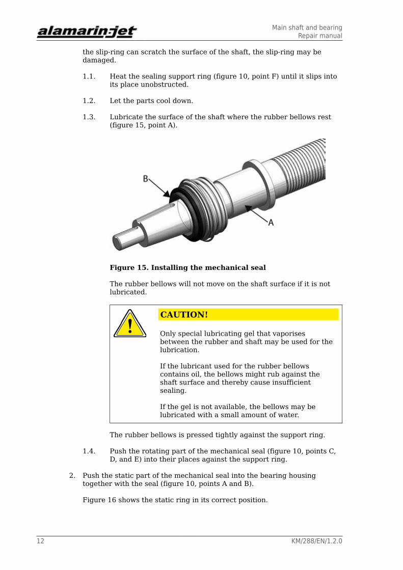
1. Install the mechanical seal.
Be careful not to damage the slip-ring (figure 15, point B) duringinstallation. If the seal is pressed into its place in a slanted position, and
Main shaft and bearingRepair manual
12 KM/288/EN/1.2.0
the slip-ring can scratch the surface of the shaft, the slip-ring may bedamaged.
1.1. Heat the sealing support ring (figure 10, point F) until it slips intoits place unobstructed.
1.2. Let the parts cool down.
1.3. Lubricate the surface of the shaft where the rubber bellows rest(figure 15, point A).
Figure 15. Installing the mechanical seal
The rubber bellows will not move on the shaft surface if it is notlubricated.
CAUTION!
Only special lubricating gel that vaporisesbetween the rubber and shaft may be used for thelubrication.
If the lubricant used for the rubber bellowscontains oil, the bellows might rub against theshaft surface and thereby cause insufficientsealing.
If the gel is not available, the bellows may belubricated with a small amount of water.
The rubber bellows is pressed tightly against the support ring.
1.4. Push the rotating part of the mechanical seal (figure 10, points C,D, and E) into their places against the support ring.
2. Push the static part of the mechanical seal into the bearing housingtogether with the seal (figure 10, points A and B).
Figure 16 shows the static ring in its correct position.

Main shaft and bearingRepair manual
KM/288/EN/1.2.0 13
Figure 16. Static ring
3. Push the bearings in the bearing housing in the right way (figure 17).
Figure 17. Pushing the bearings in the bearing housing
Figure 18 shows a cross-section of the bearing housing with the bearingsin place.
Figure 18. Bearing housing (cross-section)

Main shaft and bearingRepair manual
14 KM/288/EN/1.2.0
4. Push the fully assembled bearing housing onto the shaft according tofigure 17.
Please note that the bearings may complicate the sliding. Lubricationmakes it easier to push the bearing housing into its proper place.
5. Push the safety plate and the spinner nut onto the shaft.
The safety plate wedge (figure 19, point A) must point towards thebearing. The wedge is set onto the level surface on the shaft (figure 19,point B).
Figure 19. Safety plate wedge
6. Screw the spinner nut into place.
The tightening torque is 150 Nm.
7. Push one locking blade into the groove on the nut (figure 20, point A).
Figure 20. Locking blade
8. Place the o-ring that is used between the bearing housing and its coverinto place on the outer race of the bearing (figure 20, point B).
9. Push the shaft seal into the bearing housing cover with the seal lip towardsthe bearings (figures 21 and 22).

Main shaft and bearingRepair manual
KM/288/EN/1.2.0 15
Figure 21. Attaching the shaft seal
Figure 22. Shaft seal
10. Install the bearing housing cover in its place with the o-ring (figure 20,point B) between the housings.
11. Install the o-ring (figure 23).

Main shaft and bearingRepair manual
16 KM/288/EN/1.2.0
Figure 23. O-ring
2.1.4. Installing the front bearing
Assemble the front bearing before installing (section 2.1.3. Assembly of the frontbearing, page 11).
Front bearing installation:
1. Clean the part of the jet's body where the bearing housing is to beinstalled.
The installation surface must be free of any old sealing compound or otherimpurities and be straight.
2. Ensure the sealing by spreading sealing compound (such as Sikaflex 221)on the shoulder (figure 24) at the o-ring.
Figure 24. Shoulder
3. Push the shaft bearing into its place through the hole in the jet's body(figure 25, point A), and tighten the bearing housing fastening screws (6 intotal, figure 25, point B).

Main shaft and bearingRepair manual
KM/288/EN/1.2.0 17
The tightening torque of the screws is 50 Nm.
Figure 25. Attaching the bearing housing
4. If necessary, install the new coupling flange shaft seal (figure 26).
Figure 26. Installing the shaft seal
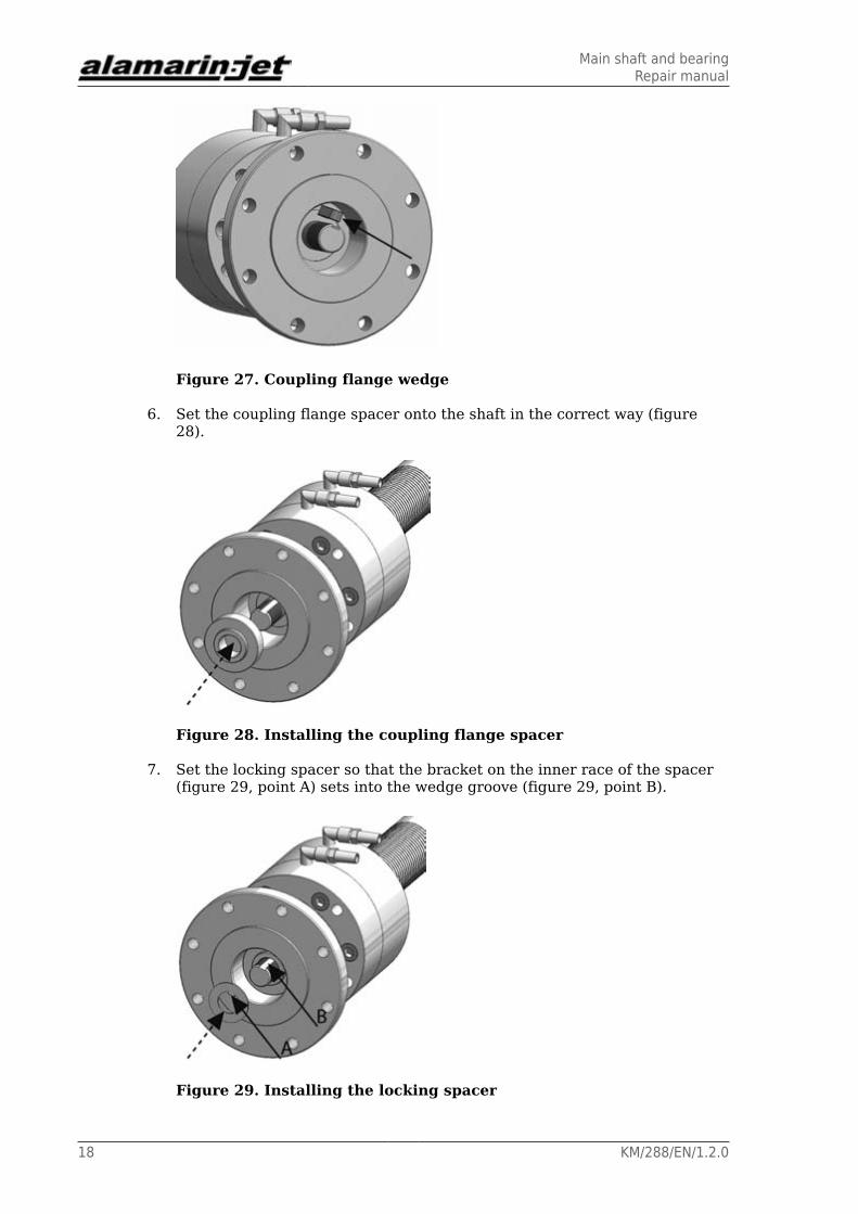
5. Push the coupling flange wedge into the groove (figure 27) and push thecoupling flange to the end of the shaft.
Please note that the wedge must not be entirely within the groove so thatthe shaft seal can fit over it. When the coupling flange is in its place, pushthe wedge entirely into the groove.
Main shaft and bearingRepair manual
18 KM/288/EN/1.2.0
Figure 27. Coupling flange wedge
6. Set the coupling flange spacer onto the shaft in the correct way (figure28).
Figure 28. Installing the coupling flange spacer
7. Set the locking spacer so that the bracket on the inner race of the spacer(figure 29, point A) sets into the wedge groove (figure 29, point B).
Figure 29. Installing the locking spacer

Main shaft and bearingRepair manual
KM/288/EN/1.2.0 19
8. Tighten the coupling flange fastening nut.
The tightening torque is 125 Nm.
9. Bend the spacer from the outer race in order to lock the nut in its place(figure 30).
For this, you will need a steel pin with an L-shaped point.
Figure 30. Bending the spacer
10. Install the stator (section 6.3. Installing the stator, page 66).
11. Install the hydraulic pump (section 4.3.3. Installing the hydraulic pump, page50).
2.2. Rear-end bearing
2.2.1. Rear-end bearing disassembly
Rear-end bearing disassembly:
1. Remove the stator (section 6.1. Removing the stator, page 63).
The rear bearing housing is attached to the stator with three screws. Thescrews are under the grease cup.
2. Remove the grease cup by rotating it with pliers, for example (figure 31).

Main shaft and bearingRepair manual
20 KM/288/EN/1.2.0
Figure 31. Removing the grease cup
3. Unscrew the bearing housing screws (figure 32, point A) remove the sealblanking plate (figure 32, point B).
Figure 32. Removing the rear bearing housing
4. Screw one of the fastening screws into the threaded hole under theblanking plate (figure 33).
Figure 33. Extracting the rear bearing housing

Main shaft and bearingRepair manual
KM/288/EN/1.2.0 21
5. Tighten the screw carefully until the bearing housing comes loose.
6. Pull the bearing housing off the stator.
Newer models:
1. Remove the stator (section 6.1. Removing the stator, page 63).
2. The rear bearing housing is attached to the stator with three screws(figure 34). Undo the screws and remove the plastic cover.
Figure 34. Rear bearing housing screws
3. Screw one of the fastening screws into the threaded hole under theblanking plate (figure 35).
Figure 35. Detaching the rear bearing housing from the stator
4. Tighten the screw carefully until the bearing housing comes loose.
5. Pull the bearing housing off the stator.
2.2.2. Repairing the rear-end bearings
Main shaft and bearingRepair manual
22 KM/288/EN/1.2.0
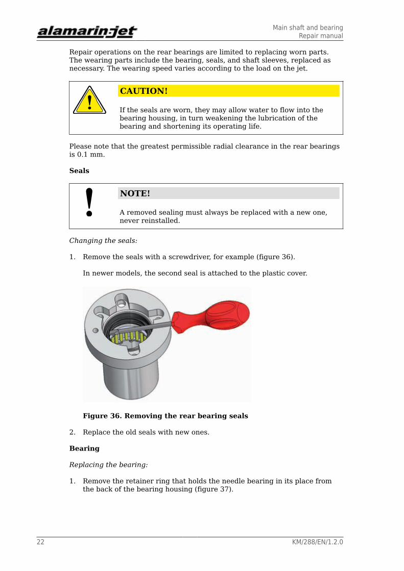
Repair operations on the rear bearings are limited to replacing worn parts.The wearing parts include the bearing, seals, and shaft sleeves, replaced asnecessary. The wearing speed varies according to the load on the jet.
CAUTION!
If the seals are worn, they may allow water to flow into thebearing housing, in turn weakening the lubrication of thebearing and shortening its operating life.
Please note that the greatest permissible radial clearance in the rear bearingsis 0.1 mm.
Seals
NOTE!
A removed sealing must always be replaced with a new one,never reinstalled.
Changing the seals:
1. Remove the seals with a screwdriver, for example (figure 36).
In newer models, the second seal is attached to the plastic cover.
Figure 36. Removing the rear bearing seals
2. Replace the old seals with new ones.
Bearing
Replacing the bearing:
1. Remove the retainer ring that holds the needle bearing in its place fromthe back of the bearing housing (figure 37).

Main shaft and bearingRepair manual
KM/288/EN/1.2.0 23
Figure 37. Retainer ring
2. Push the bearing out of the housing from the front side.
There are holes on the housing race (figure 38) to allow pushing thebearing with a mandrel, for example.
Figure 38. Recess allows for the easy removal of the bearing
2.2.3. Assembly of the rear-end bearing
Assembly of the rear bearing:
1. Push the bearing into the bearing housing from the back (figure 39).
Use a bearing retaining compound to ensure that the bearing stays in itsplace.

Main shaft and bearingRepair manual
24 KM/288/EN/1.2.0
Figure 39. Assembly of the rear bearing
2. Push the locking ring into its groove in the bearing housing (figure 39,point A).
3. Push the seals (2 in total) into their places from the front of the bearinghousing.
In newer models, the second seal is attached to the plastic cover.Ensurethat the seals are inserted in the correct way (figures 40 and 41 ).
Figure 40. Installation direction of the seals

Main shaft and bearingRepair manual
KM/288/EN/1.2.0 25
Figure 41. Installation direction of the seals in newer models
2.2.4. Installing the rear-end bearing
Before installation, ensure that the bearing housing hole in the stator is cleanand intact.
Installing the rear-end bearing:
1. Spread adhesive sealing compound around the bearing housing on thearea indicated in figure 42.
Figure 42. Spreading area of the adhesive compound
2. Push the bearing housing into the hole on the stator (figure 43, point A).

Main shaft and bearingRepair manual
26 KM/288/EN/1.2.0
Figure 43. Installing the blanking plate
3. Set the seal blanking plate (figure 43, point B) so that the holes are in linewith the holes on the bearing housing. Tighten the fastening screws (3 intotal, figure 43, point C).
Newer models do not have a blanking plate. Instead, the screws are usedto attach the plastic cover and the seals are left between the cover and thehousing.
The tightening torque of the screws is 10 Nm.
4. Remove excess adhesive compound from the hole (figure 43, point D).
5. Spread sealing and adhesive compound onto the thread of the grease cup(figure 44, point A), and screw the grease cup into its place (figure 44,point B).
Newer models do not have a separate grease cup.
Figure 44. Attaching the grease cup
6. Install the sleeves at the end of the shaft onto the shaft together with theo-rings.
The correct installation sequence is illustrated in figure 45.

Main shaft and bearingRepair manual
KM/288/EN/1.2.0 27
Use thread locking compound on the fastening screw in order to preventany unintentional loosening of the screw.
Figure 45. Installation sequence of the sleeves
7. Install the stator (section 6.3. Installing the stator, page 66).
2.3. Intermediate shaftThe intermediate shaft is the transmission shaft between the motor and jet.Usually, the intermediate shaft has been acquired and installed by the boatmanufacturer.
The most common types of intermediate shaft are the constant speed shaft andthe cardan shaft. In addition, various flexible shaft couplings are used.
The intermediate shaft is attached to the jet's coupling flange and the flywheelor gearbox. An adapter flange can be used between the jet and the shaft.
The manufacturer's instructions must always be followed in the maintenance,repair, and installation of the intermediate shaft.

Main shaft and bearingRepair manual
28 KM/288/EN/1.2.0

ImpellerRepair manual
KM/288/EN/1.2.0 29
3. ImpellerThe impeller (figure 46, point A) is attached to the jet's main shaft. As theimpeller rotates, it generates pressure that is then transformed into the flowrate.
Figure 46. Impeller
The impeller is attached to the shaft using a plastic cone (figure 46, point B),tightened between the impeller and shaft using three screws (figure 46, pointC). The torque is transmitted to the shaft using a wedge (figure 46, point D).
The impeller is located in the cone duct, which allows the gap between theblade and the duct wall to be quite small. The duct is made of acid-proof steeland does not need to be replaced.
There are rings of various thicknesses (figure 47, point A) on the front side ofthe impeller. These define the location of the impeller in the duct and transmitthe thrust from the impeller to the shaft. An insulating ring (figure 47, pointB, and figure 52), with one part in plastic and one in steel, must always bepresent in front of the impeller. The ring galvanically insulates the impellerfrom the shaft. In some cases, the insulating ring is made completely of plasticand larger in diameter.
Figure 47. Impeller rings
3.1. Impeller typeThe type of the impeller is defined according to the number, pitch, and surfacearea of the blades. The number and total pitch of the blades are unambiguous,

ImpellerRepair manual
30 KM/288/EN/1.2.0
but the surface area may vary according to the diameter and length of theblades.
The impeller type that is used varies according to the situation because theAJ 288 can be attached to various types of motors. Therefore, each impellermust be type-marked. The marking is stamped on the rear side of the impeller(figure 48). The type of the impeller must be declared, for example, whenordering a new impeller.
Figure 48. Type marking on the rear side
3.2. Removing the impeller
Before removing the impeller, remove the stator (section 6.1. Removing thestator, page 63).
Removing the impeller:
1. Open the impeller fastening cone screws (3 pcs, figure 46, point C).
2. Insert one of the screws into the threaded hole (figure 49) and tightenuntil the cone comes loose.
If the cone is stuck, insert and tighten a screw in another threaded hole.
Figure 49. Removing the impeller

ImpellerRepair manual
KM/288/EN/1.2.0 31
3. Pull the impeller off of the shaft and remove the wedge from the groove.
3.3. Repairing the impeller
Minor damages on the impeller can be repaired, such as sanding the frontedge or repairing bent blades.
NOTE!
The impeller must be balanced after any repair operations.
If the diameter of the impeller becomes too small, the impeller must bereplaced.
The impeller is manufactured from acid-proof steel (EN 1.4460).
Sanding the front edge
If necessary, a worn front edge can be sanded down. Please note that the frontedge may not be too sharp or too round. A suitable rounding is approximately r= 1 mm (figure 50).
Figure 50. Front edge
Repairing bent blades
Bends in the blades can be carefully tapped back into their original shape witha hammer.
3.4. Installing the impeller

ImpellerRepair manual
32 KM/288/EN/1.2.0
Installing the impeller:
1. Set the fastening cone to the impeller hub and tighten the three screws(figure 51, point A) so that they are finger-tight.
The mounting cone wedge groove must line up with the mark stamped onthe impeller hub (figure 51, point B).
Figure 51. Attaching the mounting cone
2. Push the adjuster sleeve and the insulating ring onto the shaft.
The position of the insulating ring must prevent the plastic ring (figure 52,point A) from touching the hub.
The type of insulating ring varies according to the shape of the impellerhub. In some impellers, it is made entirely of plastic (figure 52, point C).
Figure 52. Insulating ring
3. Push the impeller onto the shaft and push it as far into the duct as it willgo.
A gap is left between the adjuster sleeve and impeller (figure 53, pointA), which must be filled with adjuster shims. If possible, measure the gapthrough the inspection hatch. This allows you to insert the correct numberof adjuster shims into the gap.

ImpellerRepair manual
KM/288/EN/1.2.0 33
Figure 53. Location of the impeller
4. Pull the impeller off of the shaft.
5. Add shims onto the shaft until the impeller blades no longer touch thewalls of the duct.
Please note that the weight of the shaft and impeller will pull the complexdownwards, creating a larger gap above it.
6. Adjust the impeller so that the gap between the blade and duct is 0.4 to0.6 mm for each blade (figure 53, point C).
7. When the gap is adjusted, remove the impeller from the shaft and insertthe wedge into its groove (figure 53, point B).
8. Push the impeller onto the shaft tightly against the adjuster shims andtighten the screws evenly.
The tightening torque is 20 Nm.
The impeller will pull slightly backwards and the adjuster shims will sitloosely in front of it. As the impeller is being loaded, it will sit against theshims.
9. Attach the stator (section 6.3. Installing the stator, page 66).
10. If you opened the inspection hatch in step 3, close it now.
11. If possible, rotate the shaft manually from the engine room
to ensure that the location of the impeller is correct.
ImpellerRepair manual
34 KM/288/EN/1.2.0

Reversing deflector and operating hydraulicsRepair manual
KM/288/EN/1.2.0 35
4. Reversing deflector and operating hydraulicsThe purpose of the reversing deflector is to create sufficient reverse thrust forreversing the boat. When the deflector (figure 54, point A) is lowered in frontof the jet flow, it will turn the jet flow entirely or partially towards the bow,creating thrust. The operating principle allows for stopping even from highspeeds because the deflector can be lowered even at full speed.
The reversing deflector is used through a hydraulic cylinder, controlledmechanically (figure 54, point B). A cable runs from the handle in the cabin tothe operating lever of the cylinder (figure 54, point C). The hydraulic cylinderreceives its power from a pump integrated in the jet (figure 54, point D),rotated from the coupling flange with a V belt.
Figure 54. Reversing deflector and operating hydraulics
4.1. Reversing deflector
4.1.1. Removing the reversing deflector
Removing the reversing deflector:
1. Open the knee bolt of the connecting rod between the hydraulic cylinderand the reversing deflector (figure 55, point A).

Reversing deflector and operating hydraulicsRepair manual
36 KM/288/EN/1.2.0
Figure 55. Removing the reversing deflector
2. Remove the zinc anodes from the top of the joint pegs of the deflector onboth sides of the jet (figure 55, point B).
3. Open the four joint peg screws (4 pcs, figure 56).
WARNING!
Be careful not to drop the deflector.
The deflector weighs approximately 15 kg.
Figure 56. Joint peg screws
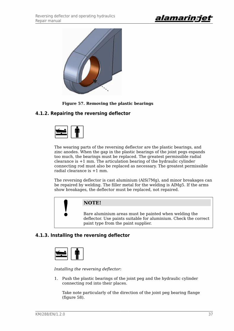
4. If you must replace the plastic bearings on the joint pegs, they can beremoved with a suitable mandrel.
The plastic bearings are pushed to their place and can be removed bypushing (figure 57).
Reversing deflector and operating hydraulicsRepair manual
KM/288/EN/1.2.0 37
Figure 57. Removing the plastic bearings
4.1.2. Repairing the reversing deflector
The wearing parts of the reversing deflector are the plastic bearings, andzinc anodes. When the gap in the plastic bearings of the joint pegs expandstoo much, the bearings must be replaced. The greatest permissible radialclearance is +1 mm. The articulation bearing of the hydraulic cylinderconnecting rod must also be replaced as necessary. The greatest permissibleradial clearance is +1 mm.
The reversing deflector is cast aluminium (AlSi7Mg), and minor breakages canbe repaired by welding. The filler metal for the welding is AlMg5. If the armsshow breakages, the deflector must be replaced, not repaired.
NOTE!
Bare aluminium areas must be painted when welding thedeflector. Use paints suitable for aluminium. Check the correctpaint type from the paint supplier.
4.1.3. Installing the reversing deflector
Installing the reversing deflector:
1. Push the plastic bearings of the joint peg and the hydraulic cylinderconnecting rod into their places.
Take note particularly of the direction of the joint peg bearing flange(figure 58).

Reversing deflector and operating hydraulicsRepair manual
38 KM/288/EN/1.2.0
Figure 58. Direction of the plastic bearing flange
2. Lift the reversing deflector in place and push the joint pegs in the holes.
3. Tighten the fastening screws (4 on each side) (figure 59).
Figure 59. Attaching the joint pegs
4. Attach the zinc anodes on top of the joint pegs (figure 55, point B).
5. Attach the knee bolt of the hydraulic cylinder connecting rod (figure 55,point A).
Please note that there must be a sleeve in the reversing deflector's hole.
4.2. Operating hydraulics
4.2.1. Removing the cylinder
Before you remove the cylinder, make sure you have a container for drainingthe oil from the hoses. Please note that it may not be necessary to completelydrain the system: you can also put plugs at the ends of the hoses.

Reversing deflector and operating hydraulicsRepair manual
KM/288/EN/1.2.0 39
Removing the cylinder:
1. Remove the cable from the cylinder.
1.1. Remove the cable angle joint (figure 60, point A) from the controllever.
Figure 60. Removing the cable
1.2. Remove the saddle mounting from the cable clamp (figure 60,point B).
2. Remove the cylinder pressure hose (figure 61, point A) and return hose(figure 61, point B) from the valve and drain the oil into a container.
Alternatively, you can plug the ends of the hoses.
Figure 61. Removing the hoses
3. Open the knee bolt of the connecting rod between the hydraulic cylinderand the reversing deflector (figure 62, point A).
Reversing deflector and operating hydraulicsRepair manual
40 KM/288/EN/1.2.0
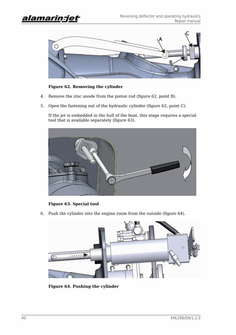
Figure 62. Removing the cylinder
4. Remove the zinc anode from the piston rod (figure 62, point B).
5. Open the fastening nut of the hydraulic cylinder (figure 62, point C).
If the jet is embedded in the hull of the boat, this stage requires a specialtool that is available separately (figure 63).
Figure 63. Special tool
6. Push the cylinder into the engine room from the outside (figure 64).
Figure 64. Pushing the cylinder

Reversing deflector and operating hydraulicsRepair manual
KM/288/EN/1.2.0 41
4.2.2. Repairing the cylinder
Worn or damaged parts of the cylinder can be replaced.
NOTE!
Only a person with appropriate training is allowed to open thecylinder or carry out the maintenance and repair operations ofthe cylinder.
4.2.3. Installing the cylinder
Installing the cylinder:
1. Make sure that the cylinder goes into place without sealing compound.
2. Make sure that the wedge is in place (figure 65, point A).
The wedge ensures that the cylinder is in the right position and that themovement range remains correct.
Figure 65. Cylinder wedge
3. Spread sealing compound into point B, as indicated in Figure 65 so that itseals the bushing.
4. Push the cylinder through the hole, insert the spacer (figure 66, point A)into its place, and tighten the screw (figure 66, point B).
The tightening torque of the nut is 100 Nm.

Reversing deflector and operating hydraulicsRepair manual
42 KM/288/EN/1.2.0
Figure 66. Cylinder spacer and nut
There is a special tool available for screwing the nuts that can be usedwhen the propulsion unit is embedded deep in the hull of the boat (figures67 and 63).
Figure 67. Propulsion unit embedded deep in the hull of the boat
5. Make sure that no sealing compound is on the piston rod.
If there is sealing compound on the rod, it must be wiped off.
6. Install the reversing deflector (section 4.1.3. Installing the reversingdeflector, page 37).
7. Install the rod between the cylinder and the deflector (figure 68, point A).

Reversing deflector and operating hydraulicsRepair manual
KM/288/EN/1.2.0 43
Figure 68. The rod between the hydraulic cylinder and thereversing deflector
8. Install the zinc anode to the piston rod.
Ensure that the zinc anode (figure 68, point B) does not prevent thedeflector from moving all the way up.
4.2.4. Cylinder adjustment
When you start the engine for the first time, make sure that you have oilavailable to add to the reversing deflector control hydraulic system.
Fill the reservoir with oil before you start the engine. After you start theengine and put it into forward gear, the oil is transferred from the reservoirinto the system and the pump automatically removes air from the system. Ifthe oil level decreases in the reservoir, add some oil to the reservoir throughthe cap. There is a dipstick in the reservoir that you can use to check the oillevel (figure 69). Every now and then, move the hydraulic cylinder's operatinglever back and forth (figure 70, point A) so that the cylinder fills with oil.

Reversing deflector and operating hydraulicsRepair manual
44 KM/288/EN/1.2.0
Figure 69. Checking the oil level
A Maximum levelB Minimum levelC Cap
Figure 70. Operating lever
Adjusting the cylinder:
1. Detach the control cable from the end of the cylinder operating lever(figure 71, point A).
Reversing deflector and operating hydraulicsRepair manual
KM/288/EN/1.2.0 45
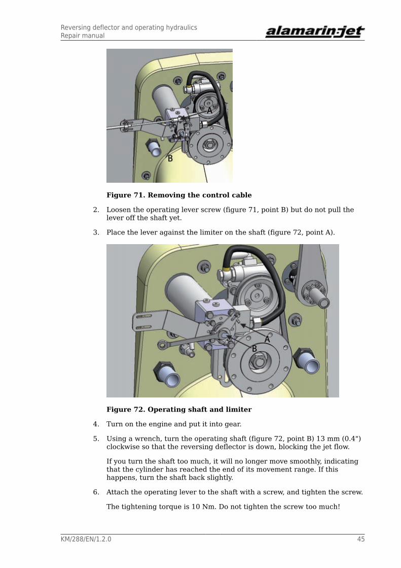
Figure 71. Removing the control cable
2. Loosen the operating lever screw (figure 71, point B) but do not pull thelever off the shaft yet.
3. Place the lever against the limiter on the shaft (figure 72, point A).
Figure 72. Operating shaft and limiter
4. Turn on the engine and put it into gear.
5. Using a wrench, turn the operating shaft (figure 72, point B) 13 mm (0.4")clockwise so that the reversing deflector is down, blocking the jet flow.
If you turn the shaft too much, it will no longer move smoothly, indicatingthat the cylinder has reached the end of its movement range. If thishappens, turn the shaft back slightly.
6. Attach the operating lever to the shaft with a screw, and tighten the screw.
The tightening torque is 10 Nm. Do not tighten the screw too much!

Reversing deflector and operating hydraulicsRepair manual
46 KM/288/EN/1.2.0
7. Attach the control cable to the screw at the end of the operating lever(figure 71, point A).
8. Use the control system in the cabin to check that the deflector can move tothe up and down positions.
In the up position, the deflector does not block the jet flow (figure 73). Inthe down position, the top of the reversing deflector nearly touches thesteering nozzle (figure 74).
Figure 73. Deflector in the up position
Figure 74. Deflector in the down position
4.3. Hydraulic pump
4.3.1. Removing the hydraulic pump
Before you remove the hydraulic pump, ensure that you have a container fordraining the oil from the hoses. Please note that it may not be necessary tocompletely drain the system: you can also put plugs at the ends of the hoses.

Reversing deflector and operating hydraulicsRepair manual
KM/288/EN/1.2.0 47
Removing the hydraulic pump:
1. Remove the hydraulic pump pressure hose (figure 75, point A) and suctionhose (figure 75, point B) and drain the oil into a container.
Alternatively, you can plug the ends of the hoses.
Figure 75. Hoses of the hydraulic pump
2. Remove the hydraulic pump rack by opening its fastening screws.
The rack is attached to the front surface of the bearing housing with fouscrews, two on each side of the pump (figure 76).
Figure 76. Hydraulic pump rack fastening screws
3. Remove the hydraulic pump from the rack by opening its three fasteningscrews (figure 77).

Reversing deflector and operating hydraulicsRepair manual
48 KM/288/EN/1.2.0
Figure 77. Hydraulic pump fastening screws
4.3.2. Repairing the hydraulic pump
A worn belt pulley in the hydraulic pump can be replaced. It can also bereplaced with the pump attached to the rack.
The pump's pressure relief valve may get clogged up with debris, which maycause the pump to malfunction. The pressure relief valve can be checked andcleaned even when the pump is attached to its rack.
Replacing the belt pulley:
1. Loosen the fastening screws of the hydraulic pump rack (figure 76).
2. Open the three screws that attach the belt pulley to the rack (3 pcs, figure78).
Figure 78. Belt pulley fastening screws
3. Remove the old belt pulley.
4. Fit in the new belt pulley.

Reversing deflector and operating hydraulicsRepair manual
KM/288/EN/1.2.0 49
5. Tighten the screws.
The tightening torque is 25 Nm. Use thread locking compound.
Pressure relief valve disassembly
Reserve a container for this procedure into which you can drain the oil fromthe partially dissembled system.
1. Open the cylinder-side end of the pressure hose and disconnect thepressure hose from the pump.
If the pump-side end of the hose is equipped with a banjo connection, thecylinder-side connector does not need to be detached.
2. Open the adapter nut (figure 79)
Figure 79. Hydraulic pump pressure relief valve
3. Lift out the pressure relief valve (figure 80) and clean it of any debris andimpurities.
Figure 80. The hydraulic pump and the pressure relief valve
4. Set the cleaned pressure relief valve back in the pump.
5. Tighten the adapter nut.
The tightening torque is 40 Nm.

Reversing deflector and operating hydraulicsRepair manual
50 KM/288/EN/1.2.0
4.3.3. Installing the hydraulic pump
Installing the hydraulic pump:
1. Mount the hydraulic pump in the rack using fastening screws (figure 77).
The tightening torque is 25 Nm. Use thread locking compound.
2. Set the rack against the front surface of the bearing housing and tightenthe fastening screws (figure 76) loosely.
Use thread locking compound.
3. Set the belt in its place and lift the rack until the belt tightens.
4. Tighten the rack fastening screws at the same time.
The tightening torque is 50 Nm.
5. Install the pressure hose (figure 75, point A) and return hose (figure 75,point B).
6. Fill the oil reservoir with oil and use the system (motor running, in forwardgear), moving the reversing deflector up and down several times.
This removes air from the system.
4.3.4. Replacing the oil filter
The oil filter in the oil reservoir must be replaced after every 500 operatinghours.
Replacing the oil filter:
1. Open the six cover screws (figure 81)
Figure 81. Oil reservoir cover screws

Reversing deflector and operating hydraulicsRepair manual
KM/288/EN/1.2.0 51
The filter is located under the cover and has a spring on top of it thatkeeps the filter in place (figure 82).
Figure 82. Oil filter spring
2. Remove and replace the spring and the filter.
It is not necessary to replace the spring unless it is damaged.
3. Put the cover back into place.
Make sure that the cover seal is correctly positioned in the groove (figure83, point A). The cover must also be positioned correctly so that the springis in line with its support (figure 83, point B).
Figure 83. Oil reservoir cover
4. Reattach the six cover screws (figure 81).

Reversing deflector and operating hydraulicsRepair manual
52 KM/288/EN/1.2.0

Steering nozzle and operating shaftRepair manual
KM/288/EN/1.2.0 53
5. Steering nozzle and operating shaftThe steering nozzle (figure 84, point A) is used to turn the direction of thewater from the jet, causing the boat to turn. The steering nozzle is used withthe levers (figure 84, points B and C) and shaft (figure 84, point D).
Figure 84. Steering nozzle and operating shaft
5.1. Steering nozzle
5.1.1. Removing the steering nozzle
The steering nozzle can be removed when the boat is in water, but it is easierif the boat is out of the water.
Removing the steering nozzle:
1. Lift and lock the reversing deflector in the upper position
by tying the deflector to the hull of the boat using rope, for example.
Please note that when the hydraulic system is turned off, it may not sustainthe deflector in the upper position. If you want more space for working,you can open the knee bolt of the connecting rod between the hydrauliccylinder and the reversing deflector (figure 55, point A). This will lift thereversing deflector all the way up (figure 85). The unintentional loweringof the deflector must always be prevented by tying it to the hull of theboat.
DANGER!
Always lock the reversing deflector in the upright positionwhile working.
A reversing deflector that is not locked may crashdownwards with force and strike the repair person.

Steering nozzle and operating shaftRepair manual
54 KM/288/EN/1.2.0
Figure 85. Reversing deflector in the upright position
2. Open the steering nozzle angle joint from the steering shaft (figure 86,point A).
Figure 86. Removing the steering nozzle 1
3. Open the steering nozzle joint screws (figure 86, point B, and 87).
Figure 87. Removing the steering nozzle 2

Steering nozzle and operating shaftRepair manual
KM/288/EN/1.2.0 55
5.1.2. Repairing the steering nozzle
A worn or damaged angle joint on the steering nozzle can be replaced. Alwaysreplace the entire joint, not just the damaged end. Please note that the lengthof the angle joint affects the movement of the steering nozzle. The plasticbearings of the steering nozzle are also replaceable.
The steering nozzle is cast aluminium (AlSi7Mg), and minor breakages can berepaired by welding. The filler metal for the welding is AlMg5. If the swingingarm or shaft holes show breakages, the steering nozzle must be replaced, notrepaired.
NOTE!
Bare aluminium areas must be painted when welding thesteering nozzle. Use paints suitable for aluminium. Check thecorrect paint type from the paint supplier.
Replacing the angle joint:
1. Remove the fastening screw from the nozzle (figure 88).
Figure 88. Replacing the angle joint
2. Install the new angle joint and tighten the screw.
The tightening torque is 80 Nm. Use thread locking compound.
Changing the plastic bearings:
1. Remove the old plastic bearings by pushing them from their holes (figure89).
Use a suitable mandrel, for example.

Steering nozzle and operating shaftRepair manual
56 KM/288/EN/1.2.0
Figure 89. Plastic bearings
2. Install the new bearings by pushing them into their holes.
Use a sealing and adhesive compound (such as Sikaflex 221).
5.1.3. Installing the steering nozzle
Installing the steering nozzle:
1. Attach the steering nozzle joint screws (figures 86 and 87).
Ensure that the joint screw steel sleeves are in their correct places (figure90).
Figure 90. Nozzle joint sleeves

Steering nozzle and operating shaftRepair manual
KM/288/EN/1.2.0 57
2. Tighten the joint screws.
The tightening torque is 50 Nm. Use thread locking compound.
3. Attach and tighten the steering nozzle angle joint (figure 86).
The tightening torque is 80 Nm. Use thread locking compound.
4. Lower the reversing deflector.
5. Attach the knee bolt of the connecting rod between the hydraulic cylinderand the reversing deflector (figure 55, point A).
5.2. Steering shaft
5.2.1. Removing the steering shaft
Removing the steering shaft:
1. Open the screw in the steering nozzle angle joint (figure 86, point A).
2. Remove the steering device from the front end lever (figure 91, point A).
The type of steering device varies according to the boat manufacturer. Themounting point of the steering device on the lever depends on the typeof the steering device (stroke length). Use a marker pen, for example, tomark the position of the control lever in relation to the shaft.
Figure 91. Removing the steering device
3. Loosen the screws of the lever adapter sleeve (6 in total, Figure 91, pointB).
4. Remove at least two screws and insert them into the threaded holes(figure 92).

Steering nozzle and operating shaftRepair manual
58 KM/288/EN/1.2.0
Figure 92. Threaded holes
5. Tighten the screws until the cone sleeve opens.
6. Remove the steering shaft locking ring (figure 93).
Figure 93. Steering shaft locking ring
7. Pull the steering shaft backwards from its place (figure 94).
Figure 94. Removing the steering shaft
5.2.2. Repairing the steering shaft
Replaceable parts in the steering shaft include worn bushing sleeves andbearings (figure 95) and bushing sleeve seals in the front end.

Steering nozzle and operating shaftRepair manual
KM/288/EN/1.2.0 59
Figure 95. Bushing sleeves and bearings
Replacing the bushing sleeve:
1. Open the fastening screws (3 in total, Figure 96) and push the sleeve outfrom the engine room.
Figure 96. Bushing sleeve fastening screws
2. Install the new bushing sleeve and its seals.
3. Tighten the fastening screws.
The tightening torque is 10 Nm.
Replacing the front bushing sleeve seals:
1. Remove the seals with a screwdriver, for example (figure 97).

Steering nozzle and operating shaftRepair manual
60 KM/288/EN/1.2.0
Figure 97. Removing the seals
2. Install the new seals by pushing them into their proper place by using asuitable mandrel.
Ensure that the seals are inserted the correct way (figure 98).
Figure 98. Correctly installed seal
3. Replace the o-ring at the front of the sleeve (figure 99).
Figure 99. Sleeve o-ring
Steering nozzle and operating shaftRepair manual
KM/288/EN/1.2.0 61
Replacing the bushing bearing:
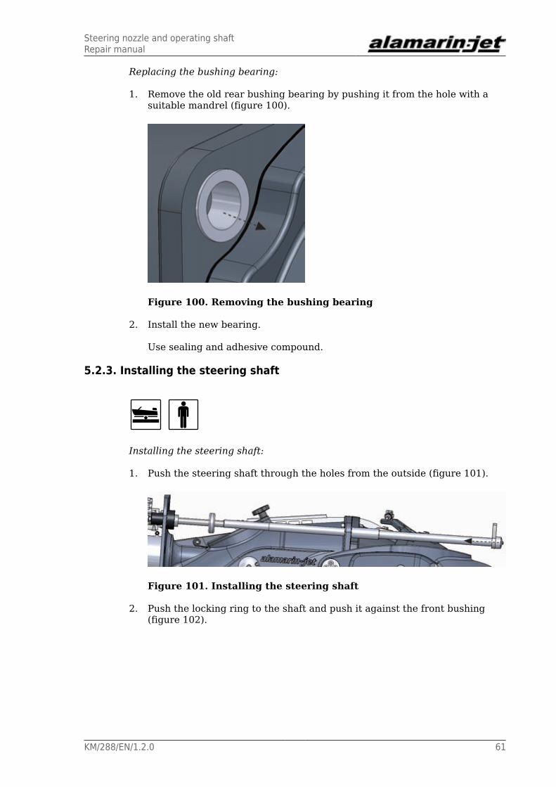
1. Remove the old rear bushing bearing by pushing it from the hole with asuitable mandrel (figure 100).
Figure 100. Removing the bushing bearing
2. Install the new bearing.
Use sealing and adhesive compound.
5.2.3. Installing the steering shaft
Installing the steering shaft:
1. Push the steering shaft through the holes from the outside (figure 101).
Figure 101. Installing the steering shaft
2. Push the locking ring to the shaft and push it against the front bushing(figure 102).
Steering nozzle and operating shaftRepair manual
62 KM/288/EN/1.2.0
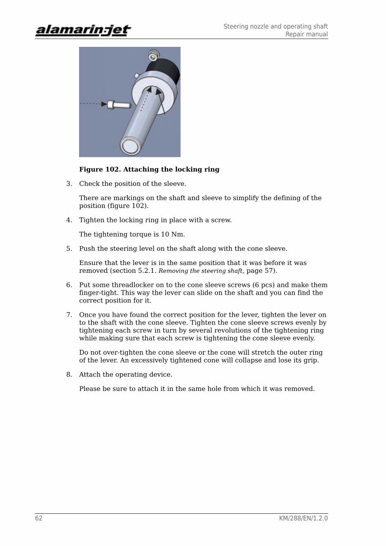
Figure 102. Attaching the locking ring
3. Check the position of the sleeve.
There are markings on the shaft and sleeve to simplify the defining of theposition (figure 102).
4. Tighten the locking ring in place with a screw.
The tightening torque is 10 Nm.
5. Push the steering level on the shaft along with the cone sleeve.
Ensure that the lever is in the same position that it was before it wasremoved (section 5.2.1. Removing the steering shaft, page 57).
6. Put some threadlocker on to the cone sleeve screws (6 pcs) and make themfinger-tight. This way the lever can slide on the shaft and you can find thecorrect position for it.
7. Once you have found the correct position for the lever, tighten the lever onto the shaft with the cone sleeve. Tighten the cone sleeve screws evenly bytightening each screw in turn by several revolutions of the tightening ringwhile making sure that each screw is tightening the cone sleeve evenly.
Do not over-tighten the cone sleeve or the cone will stretch the outer ringof the lever. An excessively tightened cone will collapse and lose its grip.
8. Attach the operating device.
Please be sure to attach it in the same hole from which it was removed.

StatorRepair manual
KM/288/EN/1.2.0 63
6. Stator
6.1. Removing the stator
The stator and steering nozzle can be removed at the same time. If necessary,the steering nozzle can then be removed from the stator.
Removing the stator:
1. Open the fastening screw in the steering nozzle angle joint from the end ofthe steering shaft (figure 86, point A).
2. Lift the reversing deflector in the upright position or all the way up(section 5.1.1. Removing the steering nozzle, page 53).
3. Open the six fastening screws of the stator (6 pcs, figure 103).
Figure 103. Stator fastening screws
4. Remove the stator from the body.
Use a flathead screwdriver. Push it between the body and the stator andcarefully crank the stator loose (figure 104, point A).
CAUTION!
Be careful.
Careless use of a screwdriver may damage paintedsurfaces.

StatorRepair manual
64 KM/288/EN/1.2.0
Figure 104. Removing the stator
5. Open the rear connection of the lubrication hose slightly (figure 104, pointB).
The stator lubricating line is full of grease, and negative pressure willbuild up when the stator is pulled out. Opening the connection makes iteasier to remove the stator.
6. Remove the steering nozzle from the stator if so required by the repairoperation (figure 87).
6.2. Repairing the stator
Replaceable parts in the stator include:
• seals (figure 105, points A and B).
• nozzle ring (figure 106, point A).
• zinc anodes (4 in total).
Figure 105. Stator seals
StatorRepair manual
KM/288/EN/1.2.0 65
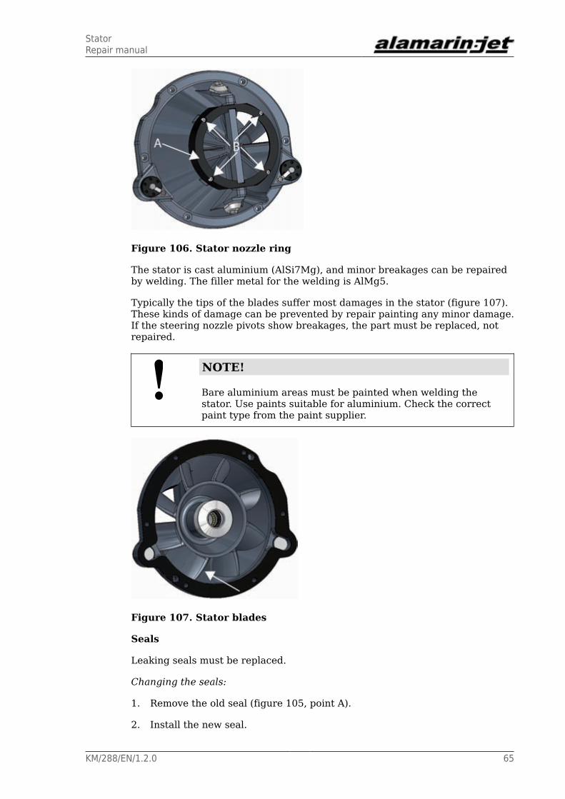
Figure 106. Stator nozzle ring
The stator is cast aluminium (AlSi7Mg), and minor breakages can be repairedby welding. The filler metal for the welding is AlMg5.
Typically the tips of the blades suffer most damages in the stator (figure 107).These kinds of damage can be prevented by repair painting any minor damage.If the steering nozzle pivots show breakages, the part must be replaced, notrepaired.
NOTE!
Bare aluminium areas must be painted when welding thestator. Use paints suitable for aluminium. Check the correctpaint type from the paint supplier.
Figure 107. Stator blades
Seals
Leaking seals must be replaced.
Changing the seals:
1. Remove the old seal (figure 105, point A).
2. Install the new seal.

StatorRepair manual
66 KM/288/EN/1.2.0
Use adhesive to keep the seal in place while the stator is installed.
Nozzle ring
The nozzle ring must be replaced if it is damaged or its seal leaks.
Changing the nozzle ring:
1. Open the nozzle ring fastening screws (4 in total, figure 106, point B).
2. Remove the old seal.
3. Attach the new seal in place of the old one.
4. Tighten the fastening screws.
The tightening torque is 10 Nm.
6.3. Installing the stator
Installing the stator
1. Push the stator into its place with the end of the shaft in the rear bearinghousing (figure 108).
The stator is centred with the dummies in the body (figure 108). Onedummy is also used as a connector for the lubrication channel. Ensure thatthe o-rings of the connector are intact. If they are damaged, the greaseintended for the rear bearing will leak out of the line.
Figure 108. Installing the stator
2. Tighten the stator fastening screws evenly.
The tightening torque is 50 Nm.

Grease recommendationsRepair manual
KM/288/EN/1.2.0 67
Appendix 1. Grease recommendationsThe grease used for lubricating the propulsion unit bearing must meet thefollowing requirements:
• lithium soap and a thickener with EP additives
• mineral oil as a base oil
• NLGI class 2
• operating temperature range -25 to 130°C (-13–266 °F)
• continuous operating temperature min. 75 °C (167 °F)
Recommended grease brands:
• Würth Multi-Purpose Grease III
• FAG Multi2
• FAG Load 220
• Mobil XHP 222
• Neste Allrex EP2
• Shell Retinax Grease EP2
A grease that has equivalent properties to those mentioned above can also beused for lubrication.

Oil recommendationsRepair manual
68 KM/288/EN/1.2.0
Appendix 2. Oil recommendationsThe operating hydraulic system of the reversing deflector and the lubricationof the front bearing are designed to use oil that is specifically intendedfor automatic transmission systems. The oil must meet the followingrequirements:
Kinematic viscosity 40℃ 33-36 mm2/sKinematic viscosity 100°C 7.1-7.7 mm2/sViscosity index min. 170Density 15°C 0.835–0.890 g/cm3
Pour point max. -42 ℃Flashpoint min. 180 ℃
Recommended oil brands:
• Mobil ATF 320
• FormulaShell ATF DEXRON III
• Neste ATF-X
• BP Autran DX III

Tightening torquesRepair manual
KM/288/EN/1.2.0 69
Appendix 3. Tightening torquesUse the tightening torques from the table 2 when tightening the propulsionunit screws. The strength grade of an acid-proof A4-80 screw is equivalent to aclass 8.8 screw.
Table 2. Tightening torques of the screws
Strength grade 8.8 10.9 12.9Thread Tightening torque
(Nm) (*)
M5 5.5 (4) 8.1 (6) 9.5 (7)M6 9.6 (7) 14 (10) 16 (12)M8 23 (17) 34 (25) 40 (30)M10 46 (34) 67 (49) 79 (58)M12 79 (58) 115 (85) 135 (100)M16 145 (107) 215 (159) 250 (184)
(*) The tightening torque in pound-feet (approximate value) is marked in thetable in parentheses after the corresponding value in Nm.
A suitable thread locking compound that is good for all purposes is one ofmedium strength, for example. Loctite 242 or similar.

Tightening torquesRepair manual
70 KM/288/EN/1.2.0