repair instructions - querotools · 2019-12-02 · these repair instructions may not be distributed...
TRANSCRIPT

Leister Technologies AG
Repair instructions
UNIROOF E Revision: B
QM
Page 1 / 34
Created 26.05.09 PRI
Released 28.05.09 PRI
Modified 23.03.13 PRI
REPAIR INSTRUCTIONS
Hot Air Welder UNIROOF E
Production code from 0847 Software version from 1.0A
© 2013 Leister Technologies AG, CH-6056 Kaegiswil These repair instructions may not be distributed or reproduced in part or in whole in any form without prior written consent from Leister Technologies AG, CH-6056 Kaegiswil. Leisters Technologies AG, CH-6056 Kaegiswil/Switzerland Tel. +41 41 662 74 74 Fax +41 41 662 74 16 www.leister.com [email protected]
Leister Technologies AG
Repair instructions
UNIROOF E Revision: B
QM
Page 2 / 34
Created 26.05.09 PRI
Released 28.05.09 PRI
Modified 23.03.13 PRI
Table of contents
1 Scope of applicability ...................................................................................................... 3
2 Safety precautions .......................................................................................................... 3
3 Remarks ........................................................................................................................... 3
4 Mechanics check ............................................................................................................. 4
5 Assembly and adjustment .............................................................................................. 5
5.1 Nozzle ....................................................................................................................... 5 5.2 Transportation lock for hot-air blower (Ghibli) ........................................................... 5 5.3 Automatic drive start-up ............................................................................................ 6
6 Electronics ....................................................................................................................... 6
6.1 Cover ........................................................................................................................ 6 6.2 Power supply cord..................................................................................................... 7
6.3 Wiring ........................................................................................................................ 8 6.4 Main switch ............................................................................................................... 9
6.5 Automatic drive start-up ............................................................................................ 9
6.6 Triac .......................................................................................................................... 9
7 Drive unit ........................................................................................................................ 10
7.1 Function check ........................................................................................................ 10 7.2 Electronic circuit TRN 05 ......................................................................................... 11 7.3 Electronic circuit ZPM 06 ........................................................................................ 12
7.4 Carbon brushes ...................................................................................................... 15 7.5 Drive motor check ................................................................................................... 16
7.6 Drive motor replacement ......................................................................................... 17 7.7 Housing assembly ................................................................................................... 19
8 Hot-air blower (Ghibli) ................................................................................................... 19
8.1 Disassembly ............................................................................................................ 19 8.2 Wiring ...................................................................................................................... 21
8.3 Heating element ...................................................................................................... 21 8.4 Thermocouple ......................................................................................................... 22 8.5 Blower motor ........................................................................................................... 24 8.6 Assembly ................................................................................................................ 24
9 Setup menu .................................................................................................................... 25
10 Possible causes of errors ............................................................................................. 27
11 Wiring diagram .............................................................................................................. 28
12 Test procedure for UNIROOF E (protection class I) ................................................... 29
13 Equipment required for Leister repair service ............................................................ 31
14 Appendix screw locking ............................................................................................... 32

Leister Technologies AG
Repair instructions
UNIROOF E Revision: B
QM
Page 3 / 34
Created 26.05.09 PRI
Released 28.05.09 PRI
Modified 23.03.13 PRI
1 Scope of applicability
These repair instructions are reserved exclusively for Leister service centres. Only experi-enced and qualified personnel trained by Leister Technologies AG, CH-6056 Kaegiswil, are allowed to do repair work on Leister tools. Additional national requirements relative to per-sonnel carrying out repair work are to be observed by each service centre.
2 Safety precautions
A well-equipped ESD-protected working place (see "Equipment required for Leister repair service") is essential for doing qualified work. For safety reasons use only identical original LEISTER replacement parts for each type of tool when servicing.
3 Remarks
If it is impossible to repair a tool, it should be returned immediately to the manufacturer, Leister Technologies AG, CH-6056 Kaegiswil, Switzerland, carriage paid to Kaegiswil. Leister will repair the tool within 24 hours after its arrival.
When ordering spare parts use the order numbers of the spare parts list. When servi-cing use only identical original Leister replacement parts!
Warning! If you open the tool or remove its parts, except the ones they are accessi-ble without using a tool, some life parts could appear. Its contact can cause danger to life! Insure tool is disconnected (unplugged) from the line/mains on every pole before any work is commenced!
Repaired tools must pass the Leister test procedure (see "Test proce-
dure") and any additional local requirements. Check with your local Statu-tory Authority for testing requirements.

Leister Technologies AG
Repair instructions
UNIROOF E Revision: B
QM
Page 4 / 34
Created 26.05.09 PRI
Released 28.05.09 PRI
Modified 23.03.13 PRI
4 Mechanics check
Check undercarriage for cracks and deformations Visual inspection
Check silicon rubber rings for possible damages
Check all moving parts for smooth running and replace them if necessary
Clean all polluted parts
Lubricate all moving parts with unpolluted grease The following parts are to be lubricated with grease (e.g. Microlube GBUY 131):
Round toothed rack
Between tool holder and guide roller
Ball bearing of swivel roller

Leister Technologies AG
Repair instructions
UNIROOF E Revision: B
QM
Page 5 / 34
Created 26.05.09 PRI
Released 28.05.09 PRI
Modified 23.03.13 PRI
5 Assembly and adjustment
The assembly has to be carried out according to exploded diagrams and spare parts lists
Note
Before assembling the tool or its components check which screws are to be locked by using Loctite 242. Therefore the appendix contains an exploded di-agram highlighting all screws to be locked.
5.1 Nozzle
Check basic nozzle adjustment according to the illustration stated below Visual inspection
5.2 Transportation lock for hot-air blower (Ghibli)
The ball pressure screw must hold the Ghibli securely in the rest position
The distance between ball pressure screw and tool holder has to be approx. 0.4 mm

Leister Technologies AG
Repair instructions
UNIROOF E Revision: B
QM
Page 6 / 34
Created 26.05.09 PRI
Released 28.05.09 PRI
Modified 23.03.13 PRI
5.3 Automatic drive start-up
Set bolt of the automatic drive start-up must be moveable against little resistance. Check whether the set bolt is bent
Nozzle 30mm: Set bolt of drive switch must protrude 22mm (see lower picture on the left)
Nozzle 40mm: Set bolt of drive switch must protrude 25mm
Set bolt must not be lubricated because it glides on teflon
6 Electronics
Warning! Disconnect the tool from the line/mains (plug unplugged) while doing the component checks described in this chapter!
6.1 Cover
Disassemble handle: Loosen countersunk screws M6x16 (2x)

Leister Technologies AG
Repair instructions
UNIROOF E Revision: B
QM
Page 7 / 34
Created 26.05.09 PRI
Released 28.05.09 PRI
Modified 23.03.13 PRI
Disassemble guide bar support: - Lock swivel roller by using multigrip
pliers (protect pliers with scraped plas-tic material, a rag or similar to avoid damage of the swivel roller)
- Loosen cheese head screw M6x25
Loosen screws M4x10 to the cover (2x) Open cover
6.2 Power supply cord
Replace the power supply cord, if it shows a short circuit, a break or mechanical damage. Continuity checker/Buzzer, Visual inspection
Notes
Do not shorten the power supply cord! If the customer did so or if a third-party cord is used, the power supply cord has to be replaced.
Check carefully the protective earth conductor for continuity.
Leister Technologies AG
Repair instructions
UNIROOF E Revision: B
QM
Page 8 / 34
Created 26.05.09 PRI
Released 28.05.09 PRI
Modified 23.03.13 PRI
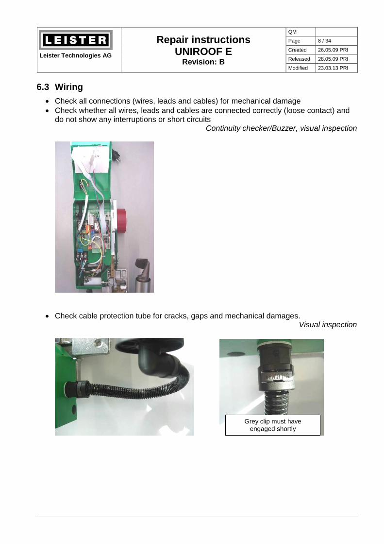
6.3 Wiring
Check all connections (wires, leads and cables) for mechanical damage
Check whether all wires, leads and cables are connected correctly (loose contact) and do not show any interruptions or short circuits
Continuity checker/Buzzer, visual inspection
Check cable protection tube for cracks, gaps and mechanical damages. Visual inspection
Grey clip must have engaged shortly

Leister Technologies AG
Repair instructions
UNIROOF E Revision: B
QM
Page 9 / 34
Created 26.05.09 PRI
Released 28.05.09 PRI
Modified 23.03.13 PRI
6.4 Main switch
Check main switch - position 0: Switch must have no continuity - position 1: Switch must have continuity Continuity checker/Buzzer
6.5 Automatic drive start-up
Check electric contact
- Drive switch not actuated: Switch must have no continuity - Drive switch actuated: Switch must have continuity Continuity checker/Buzzer
6.6 Triac
Caution! The following test procedure sometimes requires the tool to be connected to the line/mains. Insure the tool is disconnected from the line/mains before any work is commenced!
If the tool heats (possibly not pulsing) when switching on the main switch before the heating is turned on, switch the tool off, unplug the gate connection to the triac (red flex wire) and switch the tool on again. If the performance is still the same, the triac is defective.
The middle contact may not be connected!

Leister Technologies AG
Repair instructions
UNIROOF E Revision: B
QM
Page 10 / 34
Created 26.05.09 PRI
Released 28.05.09 PRI
Modified 23.03.13 PRI
7 Drive unit
7.1 Function check
Caution! The following measurement procedure sometimes requires the tool to be connected to the line/mains. Insure the tool is disconnected from the line/mains before any work is commenced!
1. Switch the tool off and disconnect (unplug) it from the line/mains 2. Connect an ammeter between the orange plug and the black flex wire of the drive
motor (see picture on the left) 3. Connect tool to line/mains and switch it on 4. Set motor speed to maximum (5m/min) 5. The current consumption must be 100..300mA Ammeter
Notes
An excessive noise of the motor indicates a bearing defect Replace motor (see chapter 7.6).
If the current consumption exceeds 300mA, the motor works with overload Possible causes: Pressure roller touches the housing or defective gearing

Leister Technologies AG
Repair instructions
UNIROOF E Revision: B
QM
Page 11 / 34
Created 26.05.09 PRI
Released 28.05.09 PRI
Modified 23.03.13 PRI
7.2 Electronic circuit TRN 05
Check electronic circuit boards for visual error indications:
Scorch marks, exploded parts
Expanded/swelled parts (e.g. transformer)
An insulation paper must be installed between housing and electronic circuit TRN 05
Fuse link defective? Visual inspection
Caution! The following measurement procedure sometimes requires the tool to be connected to the line/mains. Insure the tool is disconnected from the line/mains before any work is commenced!
If the display remains dark after switching on the main switch, check the electronic circuit TRN 05 applying appropriate line/mains voltage (according to nameplate): Voltmeter
The voltage measured at the white 2-poles terminals must be 5VDC (+/- 0.2V); use the free terminal for measuring (see picture on the left).
With the drive unit switched off, the orange 2-poles plug (see picture on the right) shows the line/mains voltage (e.g. 230V AC voltage).
Note
If the fuse link is defective test the electronic circuit ZPM 06 first (see chapter 7.3), before replacing the fuse link.

Leister Technologies AG
Repair instructions
UNIROOF E Revision: B
QM
Page 12 / 34
Created 26.05.09 PRI
Released 28.05.09 PRI
Modified 23.03.13 PRI
7.3 Electronic circuit ZPM 06
Check the electronic circuit ZPM 06 (e.g. in case of overvoltage indication, if a 230V-tool was possibly connected to 400V): Open housing, see chapter 6.1
Disassemble round belt
Loosen raised cheese head screw M4x10 and remove pressure roller carefully from the axle
Loosen screws M8x16 of the support (2x)
Loosen screw M4x10 of the heat sink (triac)

Leister Technologies AG
Repair instructions
UNIROOF E Revision: B
QM
Page 13 / 34
Created 26.05.09 PRI
Released 28.05.09 PRI
Modified 23.03.13 PRI
Loosen screws M4x10 (4x): - 1 behind electronic circuit TRN 05 - 1 next to the heat sink - 2 between the rollers
Unplug cable and ribbon cable of the elec-tronic circuit ZPM 06 Remove cable ties Unwind housing carefully

Leister Technologies AG
Repair instructions
UNIROOF E Revision: B
QM
Page 14 / 34
Created 26.05.09 PRI
Released 28.05.09 PRI
Modified 23.03.13 PRI
Connect continuity checker/buzzer to both contacts of the orange plug (see picture). If conti-nuity is detected the electronic circuit ZPM 06 is defective. Check the drive motor prior to re-place the electronic circuit (see chapter 7.5). Continuity checker/Buzzer
Desolder red flex wire leading to the upper carbon brush support of the motor. Connect con-tinuity checker/buzzer between desoldered flex wire and the lower carbon brush support (white flex wire). Connect and verify the results according to the table stated below. Soldering iron, Continuity checker/Buzzer
Lower carbon brush support Red flex wire Results
+ - Diode voltage approx. 0.5V
- + No diode voltage
(This is not a complete testing of the electronic circuit) Should this test not be successful, check drive motor (see chapter 7.5) and finally replace the electronic circuit ZPM 06.
Notes
Make sure the distance bushings (ø 3.1/6 x 5) are inserted when assembling the electronic circuit ZPM 06
Temperature limit switch and MOSFET are to be covered with thermal conducting paste when assembling
The connectors of the ribbon cable must be sealed by using silicone rubber
Lower carbon brush support
Red flex wire

Leister Technologies AG
Repair instructions
UNIROOF E Revision: B
QM
Page 15 / 34
Created 26.05.09 PRI
Released 28.05.09 PRI
Modified 23.03.13 PRI
7.4 Carbon brushes
Separation of drive unit see chapter 7.3
Loosen hexagon head screws M5x12 from the undercarriage (2x)
Carefully bend back the ears of both carbon brush supports. Caution, springs are under tension!
Check length of both carbon brushes
Replace the carbon brushes if their length measure 4mm or even less. Check both carbon brushes! If the carbon brushes are not to be replaced make sure to re-insert them the same way (abraison).

Leister Technologies AG
Repair instructions
UNIROOF E Revision: B
QM
Page 16 / 34
Created 26.05.09 PRI
Released 28.05.09 PRI
Modified 23.03.13 PRI
7.5 Drive motor check
Visual check of commutator:
Worn out lamella
Bluish discoloration
Deep grooves (U-shaped) Visual inspection Desolder red flex wire (see chapter 7.3) and measure the resistance on the carbon brushes by using an ohmmeter (see picture). Turn the commutator slowly by hand and check all la-mella. The resistance must be 50..100Ω per segment. Otherwise replace the motor (see chapter 7.6) Ohmmeter
Caution! The following measurement procedure sometimes requires the tool to be connected to the line/mains. Insure the tool is disconnected from the line/mains before any work is commenced!
With desoldered red flex wire (see chapter 7.3) connect a bridge rectifier to both carbon brush supports (see picture on the left). Allpy voltage by using a transformer and an amme-ter. Check for correct polarity. Slowly increase the voltage from 0V and check the current consumption. If the current consumption exceeds 100mA at a voltage of less than 10V, either the gear or the motor are defective remove motor (see chapter 7.6) and repeat the meas-urement without gear. Bridge rectifier, ammeter

Leister Technologies AG
Repair instructions
UNIROOF E Revision: B
QM
Page 17 / 34
Created 26.05.09 PRI
Released 28.05.09 PRI
Modified 23.03.13 PRI
7.6 Drive motor replacement
Separation of drive unit see chapter 7.4
Disassemble electronic circuit ZPM 06: - Desolder flex wires (red and white) - First loosen raised cheese head
screw M3x6 of the MOSFET - Then loosen other screws M3x12 (2x)
Loosen hexagon head screws M4x14 (2x)
Open cover of gear box: - Loosen cheese head screws M3x8
(4x) - Pay attention not to lose too much
grease
Loosen hexagon head screw M4x14 Extract motor carefully from the gear box

Leister Technologies AG
Repair instructions
UNIROOF E Revision: B
QM
Page 18 / 34
Created 26.05.09 PRI
Released 28.05.09 PRI
Modified 23.03.13 PRI
Remove split pin on suitable base (e.g. wooden plate) by using punch (ø max. 1.9mm) and hammer Pay attention the worm rests properly on the base to prevent any damage of the mo-tor ball bearings
Disassemble worm, silicone gasket, sealing of gear box and round cord from the motor
Replace motor
Assembly:
Assemble in reverse order
Check by beating whether the gearing is filled with grease up to the center level of the axle; refill if necessary
Tighten cheese head screws M3x8 (4x) of the gear box cover with 1.2Nm only (use torque screwdriver)!

Leister Technologies AG
Repair instructions
UNIROOF E Revision: B
QM
Page 19 / 34
Created 26.05.09 PRI
Released 28.05.09 PRI
Modified 23.03.13 PRI
7.7 Housing assembly
Assembly:
Check in the appendix which screws are to be mechanically secured
Adjust the housing in such a way that the distance to the drive roller is steady all around
Heat sink for triac must be covered with thermal conducting paste
8 Hot-air blower (Ghibli)
8.1 Disassembly
Disconnect all connections of the hot-air tool, remove cable ties
green white black
black
black/blue
white

Leister Technologies AG
Repair instructions
UNIROOF E Revision: B
QM
Page 20 / 34
Created 26.05.09 PRI
Released 28.05.09 PRI
Modified 23.03.13 PRI
Remove grey clip from hose screw fitting:
Unlock clip by pushing a screwdriver to one side flap and lift clip with an addi-tional screwdriver size 2
Proceed the same way from the oppo-site side and remove the clip
Remove cables including cable protection tube from the Uniroof E housing
Loosen countersunk screws M5x12 (4x) and remove Ghibli
Loosen cheese head screws M3x8 (4x) of the overlap welding nozzle
Remove mica tube and heater tube. The gasket can not be removed, because it is joined with the Ghibli housing!
Extract rubber plugs (3x) Loosen raised cheese head screws M3.5x20 (5x) Open housing

Leister Technologies AG
Repair instructions
UNIROOF E Revision: B
QM
Page 21 / 34
Created 26.05.09 PRI
Released 28.05.09 PRI
Modified 23.03.13 PRI
8.2 Wiring
Check all wires and leads for interruptions, short circuits and mechanical damage
Check correct wiring (compare with picture)
The flexible wires of the thermocouple (green and white) may not be provided with ferrules Continuity checker/Buzzer, visual inspection
8.3 Heating element
Do a visible inspection of the heating element. Replace the heating element if it is either mechanically damaged or if any heating channels are clogged.
Measure the resistance of the heating element by using an ohmmeter. Replace heating element if measured resistance deviates more than ± 10% from the value given in the table. Ohmmeter, visual inspection
Article no. Voltage [V] Power [W] Resistance [Ω]
103.604 230 2100 approx. 25
103.605 230 2750 approx. 19

Leister Technologies AG
Repair instructions
UNIROOF E Revision: B
QM
Page 22 / 34
Created 26.05.09 PRI
Released 28.05.09 PRI
Modified 23.03.13 PRI
8.4 Thermocouple
Open hot-air blower (Ghibli) according to chapter 8.1
8.4.1 Thermocouple check
Extract thermocouple connections from screwed connector and remove overlap welding nozzle including heating element (see chapter 8.1)
Check with continuity checker/buzzer whether continuity exists between shielding lead and jacket of the thermocouple. Otherwise replace thermocouple (see chapter 8.4.2)
Measure thermocouple resistance between both signal leads (green and white). Therefore the thermocouple must be cooled down to ambient temperature! Nominal value: approx. 7Ω (no short circuit or interruption)
Check insulation between both signal leads (green and white) and shielding lead. Nominal value: > 5MΩ Ohmmeter
8.4.2 Thermocouple replacement
Remove cable ties and extract thermocouple cable

Leister Technologies AG
Repair instructions
UNIROOF E Revision: B
QM
Page 23 / 34
Created 26.05.09 PRI
Released 28.05.09 PRI
Modified 23.03.13 PRI
Push distance bushing back by using pliers
Extract thermocouple carefully from its sock-et by using pliers Remove distance bushing and mount it to the replacement thermocouple
Assembly of replacement thermocouple:
Pay attention to correct cable routing
Assembly of Ghibli see chapter 8.6.
Caution! The following measurement procedure sometimes requires the tool to be connected to the line/mains. Insure the tool is disconnected from the line/mains before any work is commenced!
After thermocouple replacement the temperature offset must be re-adjusted:
Switch Uniroof E on and set temperature to 600°C (1112°F)
Wait until set temperature is reached
Move thermocouple in parallel to the nozzle and find hottest spot; make sure thermo-couple does not touch the nozzle (see picture on the right)
Re-adjust the temperature offset if the display does not agree with the actual value (see chapter 9). The maximum offset may not exceed 40°C (heating element could be de-stroyed!). If this should be the case, check thermocouple, heating element and electron-ic circuit once again and replace them if necessary. Temperature meter

Leister Technologies AG
Repair instructions
UNIROOF E Revision: B
QM
Page 24 / 34
Created 26.05.09 PRI
Released 28.05.09 PRI
Modified 23.03.13 PRI
8.5 Blower motor
Open hot-air blower (Ghibli) according to chapter 8.1
8.5.1 Function check
Caution! The following measurement procedure sometimes requires the tool to be connected to the line/mains. Insure the tool is disconnected from the line/mains before any work is commenced!
1. Switch Uniroof E off 2. Connect ammeter between terminal and
black flex wire of the blower (see pic-ture)
3. Switch the tool on 4. The current consumption must be
200..300mA Ammeter
Notes
An excessive noise of the motor indicates a bearing defect Replace motor (see chapter 7.6)
If the current consumption exceeds 300mA, the motor works with overload (e.g. mo-tor not correctly positioned, turbine touches housing)
Check carbon brushes if strange sound (stuttering) is detected
8.5.2 Carbon brushes
Extract motor from its rest. Remove carbon brushes according to chapter 7.4, measure its length and replace them, if their length is 4mm or even less. Check both carbon brushes! If the carbon brushes are not to be replaced make sure to insert them the same way (abrai-son). Re-assemble motor correctly to its rest. Sliding caliper
8.6 Assembly
Reverse order of chapter 8.1
Correct wiring see chapter 8.2
Put air filter correctly in its support
Prior to close the housing make sure the motor will be pushed to the bottom to prevent the turbine touches the housing!
Do not pinch the warning label „Hot surface“

Leister Technologies AG
Repair instructions
UNIROOF E Revision: B
QM
Page 25 / 34
Created 26.05.09 PRI
Released 28.05.09 PRI
Modified 23.03.13 PRI
9 Setup menu
(upto software release 1.0A) Modifications in the Setup menu are automatically stored
At the same time press
and switch the tool on
„WRONG KEY COMB
TURN POWER OFF“
Enter code (HMHH+-)
Serial Number
Max. Speed
5.00m/min
Temp. Offset
+0°C
Display Unit
`-`>C/m, `+`>F/ft
1.00 20
5.00 600
M - + H
H press
H press
Min. Speed
1.00m/min
Max. temperature
600°C
H press
H press
H press
H press
- + select with
- + select with
- + select with
- + select with
- + select with
year week serial number 00 00 000
M M M

Leister Technologies AG
Repair instructions
UNIROOF E Revision: B
QM
Page 26 / 34
Created 26.05.09 PRI
Released 28.05.09 PRI
Modified 23.03.13 PRI
(from software release 1.0B)
At the same time press
and switch the tool on
„WRONG KEY COMB
TURN POWER OFF“
Enter code (HMHH+-)
Serial Number
Max. Speed
5.00m/min
Temp. Offset
+0°C
Display Unit
`-`>C/m, `+`>F/ft
1.00 20
5.00 600
M - + H
H press
H press
Min. Speed
1.00m/min
Max. temperature
600°C
H press
H press
H press
H press
- + select with
- + select with
- + select with
- + select with
- + select with
year month day no. 00 00 00 0000
M M M M
Entering old 7 digit serial number: Enter week in month column Set day and first digit of serial number to 0
Leister Technologies AG
Repair instructions
UNIROOF E Revision: B
QM
Page 27 / 34
Created 26.05.09 PRI
Released 28.05.09 PRI
Modified 23.03.13 PRI
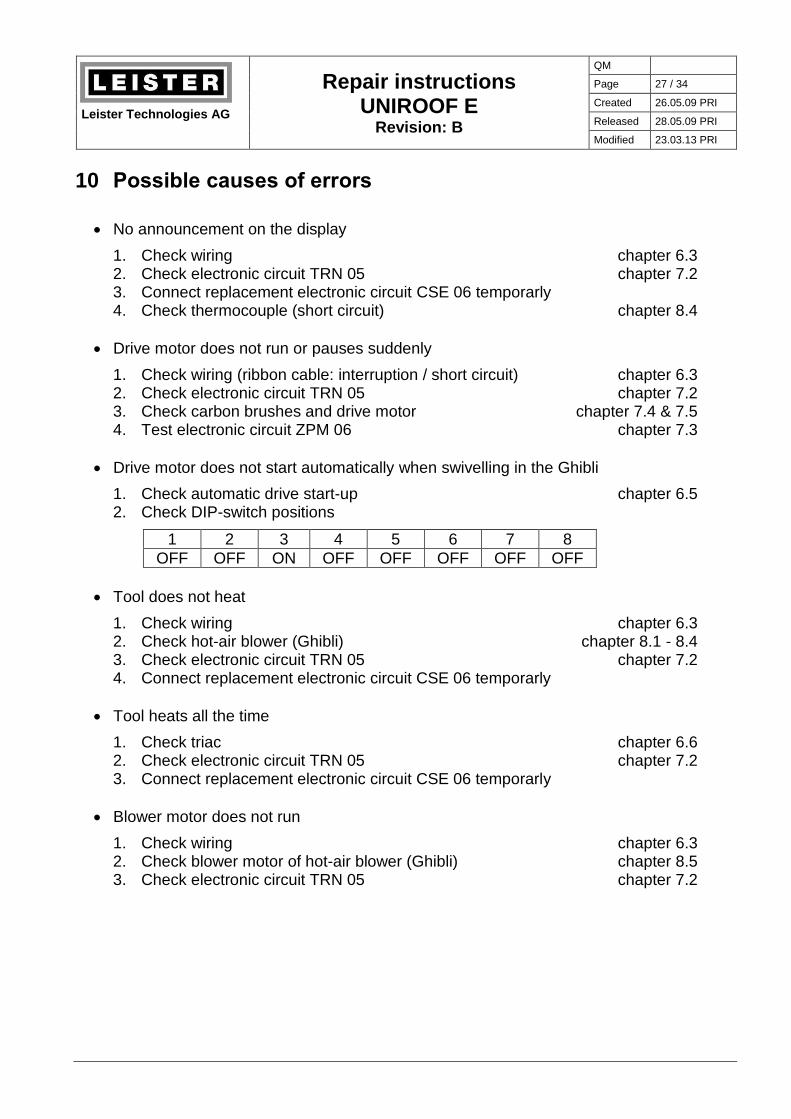
10 Possible causes of errors
No announcement on the display
1. Check wiring chapter 6.3 2. Check electronic circuit TRN 05 chapter 7.2 3. Connect replacement electronic circuit CSE 06 temporarly 4. Check thermocouple (short circuit) chapter 8.4
Drive motor does not run or pauses suddenly
1. Check wiring (ribbon cable: interruption / short circuit) chapter 6.3 2. Check electronic circuit TRN 05 chapter 7.2 3. Check carbon brushes and drive motor chapter 7.4 & 7.5 4. Test electronic circuit ZPM 06 chapter 7.3
Drive motor does not start automatically when swivelling in the Ghibli
1. Check automatic drive start-up chapter 6.5 2. Check DIP-switch positions
1 2 3 4 5 6 7 8
OFF OFF ON OFF OFF OFF OFF OFF
Tool does not heat
1. Check wiring chapter 6.3 2. Check hot-air blower (Ghibli) chapter 8.1 - 8.4 3. Check electronic circuit TRN 05 chapter 7.2 4. Connect replacement electronic circuit CSE 06 temporarly
Tool heats all the time
1. Check triac chapter 6.6 2. Check electronic circuit TRN 05 chapter 7.2 3. Connect replacement electronic circuit CSE 06 temporarly
Blower motor does not run
1. Check wiring chapter 6.3 2. Check blower motor of hot-air blower (Ghibli) chapter 8.5 3. Check electronic circuit TRN 05 chapter 7.2

Leister Technologies AG
Repair instructions
UNIROOF E Revision: B
QM
Page 28 / 34
Created 26.05.09 PRI
Released 28.05.09 PRI
Modified 23.03.13 PRI
11 Wiring diagram
bla
u /
blu
e 1
.5m
m2
sch
wa
rz /
bla
ck 2
0A
WG
bra
un
/ b
row
n 1
6A
WG
L1
10uH
L2
10uH
J2
Kle
mm
e /
Te
rmin
al
123
1A
2A
3A
bla
u /
blu
e 1
.5m
m2
blau / blue 20AWG
bra
un
/ b
row
n 1
.5m
m2
braun / brown 20AWGS
1
Sch
alte
r /
Sw
itch
12
bra
un
/ b
row
n 1
.5m
m2
MT2
MT1
Q1
TR
IAC
M2
Ge
blä
se
mo
tor
/ B
low
er
Mo
tor
C1
15
0n
F/2
75
V
J1
Kle
mm
e /
Te
rmin
al
123
1A
2A
3A
HE
1
He
ize
lem
en
t /
He
atin
g e
lem
en
t
1 2
LCD-Modul
M=
M1
Mo
tor
+-
T1
Th
erm
oe
lem
en
t /
Th
erm
oco
up
le
+ -sh
ield
TR
N0
5
TR
N0
5A
Erdung / Earthing
nc
Phase / Line
nc
Null / Neutral
Gate
Sch
rim
/ s
hie
ld
- W
eis
s /
with
e
+ G
rün
/ g
ree
n
(-)
Sig
nal
(+)
VC
C
GN
D
VS
S
Dre
hza
hl /
sp
ee
d
Ga
te_
v
Str
om
_v
/ c
urr
en
t_v
Ga
te_
t1
ZC
Te
mp
Vre
f
nc
Lim
it_
t
nc
An
fah
ren
/ d
riv
ea
wa
y
VCC
GND
Drehzahl / speed
Gate_v
Strom_v
nc
230VAC
230VAC
An
fah
rse
nso
r /
Pro
xim
ity
Sw
itch
An
fah
rse
nso
r /
Pro
xim
ity
sw
itch
(+)
Sig
nal
rot
/ re
d 2
0A
WG
ZP
M0
6
ZP
M0
6VCC
GND
Drehzahl / speed
Gate_v
Strom_v
nc
230VAC
230VAC
+PWM
-PWM
CS
E0
6
CS
E0
6
VC
C
GN
D
VS
S
Dre
hza
hl /
sp
ee
d
Ga
te_
v
Str
om
_v
/ c
urr
en
t_v
Ga
te_
t1
ZC
Te
mp
Vre
f
nc
Lim
it_
t
nc
An
fah
ren
/ d
riv
ea
wa
y
we
iss /
wh
ite
16
AW
G
Erd
un
g /
Ea
rth
ing
we
iss /
wh
ite
1.5
mm
2
Nu
ll-L
eite
r /
Ne
utr
al
Ph
ase
/ L
ine
sch
wa
rz /
bla
ck 2
0A
WG

Leister Technologies AG
Repair instructions
UNIROOF E Revision: B
QM
Page 29 / 34
Created 26.05.09 PRI
Released 28.05.09 PRI
Modified 23.03.13 PRI
M
M
12 Test procedure for UNIROOF E (protection class I)
Protective earth conductor test
Measure resistance between the the earth/ground pin of the plug and the nozzle as well as between the the earth/ground pin of the plug and the undercarriage by using the pro-tective earth conductor tester (< 0.2Ω)
Insulation test
Function check of high voltage tester: Shorten tips Signal lamp illuminates and horn sounds
Connect tool to a short circuit receptacle
Set main switch of the tool to position "1" (ON)
Apply a high voltage von 1000V (release current 100mA) for 1 second between the short circuit receptacle and the undercarriage; no flashover or breakdown must occur
Settings
Set main switch to position "0" (OFF) and connect tool to rated voltage (line/mains or transformer)
Enter the Setup menu: Press all of the four keys together and set the main switch to po-sition "1" (ON) at the same time
Enter key combination Enter serial number Max. speed 5m Min. speed 1m Max. temperature 600°C Temp. Offset 0°C (to be modified after thermocouple replacement only) Select unit °C or °F
Set main switch to position "0" (OFF)
Function test
Change to %-mode: Press keys and together and set the main switch to position "1" (ON) at the same time
Press key to deactivate the automatic restart protection
Press key once again to start the motor
Run the drive motor with max. speed (5m/min) Check percential power consumption of the drive, max. 65%
Heat the tool up to maximum temperature 600°C Check current consumption (according to nameplate)
Check display announcement 595..605°C
–
H M H H + –
+

Leister Technologies AG
Repair instructions
UNIROOF E Revision: B
QM
Page 30 / 34
Created 26.05.09 PRI
Released 28.05.09 PRI
Modified 23.03.13 PRI
After 15 minutes search for the hottest spot and measure the temperature
Actual value of temperature meter 590..610°C
Adjust temperature offset, if necessary ( Setup menu) Example: Temperature display = 600°C; temperature meter = 610°C Offset: - 10°C
Restart tool and heat it up; check temperature after another 15 minutes
Check function of the drive switch
Let the tool cool down
Check Setup menu
Checking completeness
Check ratings of the nameplate: Type, voltage, current, power consumption
Check production code / serial number
Check power supply cord mechanically and electrically (type of plug)
The following labels must be bonded: Company label LEISTER large on the side panel and small on the cover of the
electronic box Warning label „Hot surface“ and small company label LEISTER on the Ghibli hous-
ing
Check for cleanliness and possible damages

Leister Technologies AG
Repair instructions
UNIROOF E Revision: B
QM
Page 31 / 34
Created 26.05.09 PRI
Released 28.05.09 PRI
Modified 23.03.13 PRI
13 Equipment required for Leister repair service
Mobile Equipment
1 protective earth conductor tester (e.g. Elabo)
1 high voltage tester up to 4000V (e.g. Elabo, Korntal)
1 temperature meter with temperature measurement probe (e.g. Fluke, Testo)
1 multimeter with following measurement options: (e.g. Fluke) - Current - Voltage - Resistance - Continuity (test buzzer)
1 rotational speed meter
1 water column
1 soldering iron
1 complete set of tools (screw drivers etc.)
Installed equipment
ESD-protected working environment
Transformer, possibly separated into variable and isolating transformer Data: 3 x 0..500V 3 x 30A
3 built-in voltmeters (500V)
3 built-in ammeters (30A) or wattmeters
Leister Technologies AG
Repair instructions
UNIROOF E Revision: B
QM
Page 32 / 34
Created 26.05.09 PRI
Released 28.05.09 PRI
Modified 23.03.13 PRI
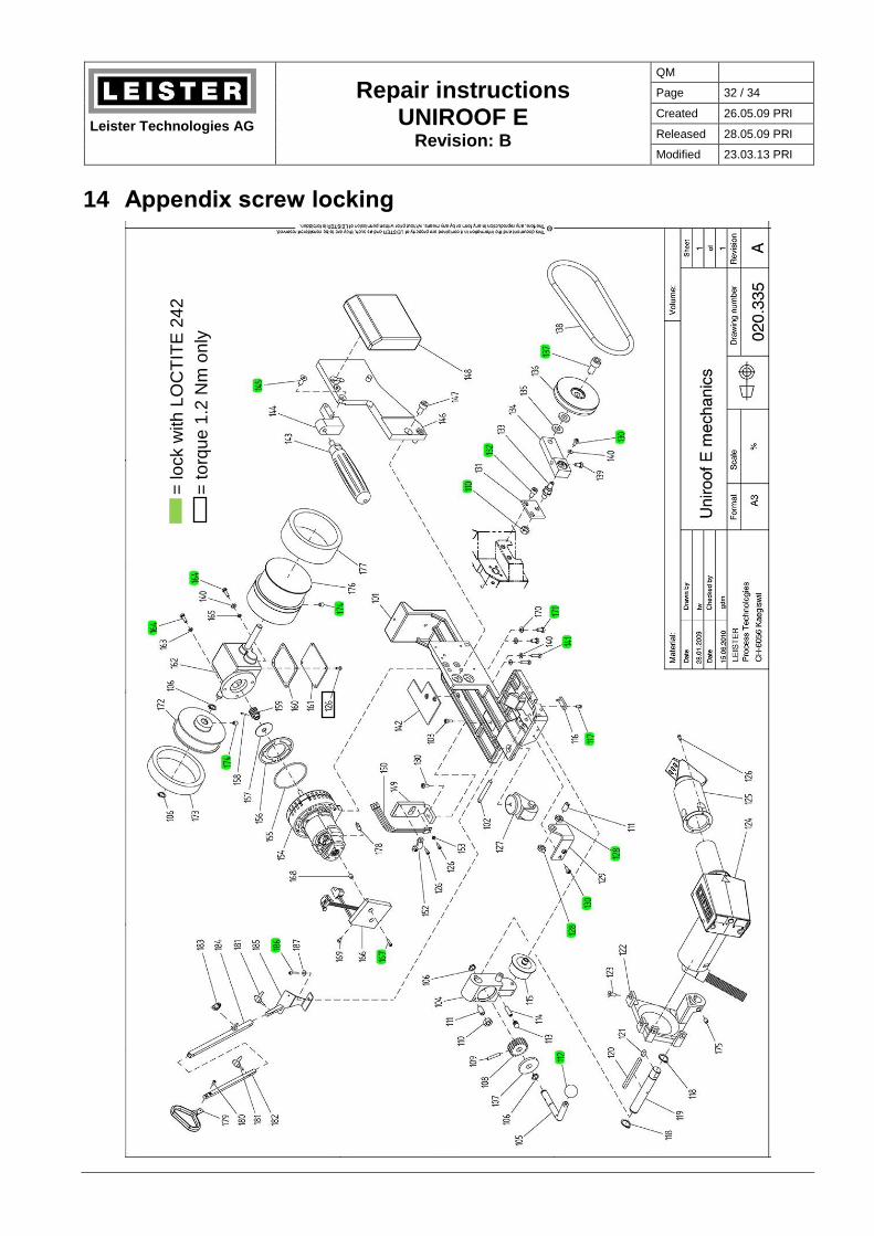
14 Appendix screw locking
= lock w
ith
LO
CT
ITE
24
2
= t
orq
ue
1.2
Nm
on
ly

Leister Technologies AG
Repair instructions
UNIROOF E Revision: B
QM
Page 33 / 34
Created 26.05.09 PRI
Released 28.05.09 PRI
Modified 23.03.13 PRI
= lock w
ith
LO
CT
ITE
24
2
= t
orq
ue
1.2
Nm
on
ly

Leister Technologies AG
Repair instructions
UNIROOF E Revision: B
QM
Page 34 / 34
Created 26.05.09 PRI
Released 28.05.09 PRI
Modified 23.03.13 PRI
= lo
ck w
ith
LO
CT
ITE
24
2