renova vacuum solutions - madan technologies · instructionsor by modifications to the system or...
TRANSCRIPT

--2RV SeriesOperating Instructions
Liquid Ring Vacuum Pumps
EnglishEnglishEnglishEnglish translationtranslationtranslationtranslation ofofofof originaloriginaloriginaloriginal operatingoperatingoperatingoperating instructionsinstructionsinstructionsinstructions
DocumentationIt is imperative to read the operating instructions prior tocommissioning!
This document as well as all documents included in the
appendix is not subject to any update service!
Subject to technical changes
RENOVA VACUUM SOLUTIONS

Operating Instructions
2RV SERIES WATER RING VACUUM PUMP
IndexIndexIndexIndex
1111 ImportantImportantImportantImportant basicbasicbasicbasic information...................................1information...................................1information...................................1information...................................1
1.1 Statement......................................................1
1.2 Warranty and liability......................................1
2222 SafetySafetySafetySafety ......................................................................2......................................................................2......................................................................2......................................................................2
2.1 Staff safety......................................................2
2.2 Working condition safety.................................2
2.3 Safety related terms........................................2
3333 DesignDesignDesignDesign andandandand functioning..........................................3functioning..........................................3functioning..........................................3functioning..........................................3
3.1 General description.........................................3
3.2 Functional principle.........................................3
3.3 Mechanical structure.......................................3
3.3.1 Sectional structure………………………3
3.3.2 2RV2/2RV5 series..........................................4
3.3.3 2RV6 series...................................................4
4444 ScopeScopeScopeScope ofofofof application.............................................5application.............................................5application.............................................5application.............................................5
4.1 Application……….............................................5
4.2 Ultimate vacuum...............................................5
4.3 Maximum discharge pressure...........................5
4.4 Gas and vapor to be pumped............................5
4.5 Operating liquid.................................................5
5555 Set-upSet-upSet-upSet-up andandandand connection.........................................6connection.........................................6connection.........................................6connection.........................................6
5.1 Transport and fixing..........................................6
5.2 Pipe connection................................................6
5.2.1 Discharge port flange……………………………6
5.2.2 Suction port flange………………………………6
5.2.3 Recommended mode of the operating liquid
connection………………………………………..7
5.3 Supply mode of operating liquid…..….......…….7
5.4 Separator………………………...……….………7
5.5 Check valve………………………………………7
5.6 Air ejector…………………………………………8
6666 Operation.................................................................9Operation.................................................................9Operation.................................................................9Operation.................................................................9
6.1 Preparation.......................................................9
6.2 Starting up and shutting down……………..…..9
6.3 Draining
off........................................................9
6.4 Prolonged shutdown period............................9
7777 Maintenance..........................................................10Maintenance..........................................................10Maintenance..........................................................10Maintenance..........................................................10
7.1 Flush the pump.............................................10
7.2 Lubrication....................................................10
7.3 Storage…………………………………………10
7.4 Troubleshooting.………………………...….…10
8888 TechnicalTechnicalTechnicalTechnical data........................................................12data........................................................12data........................................................12data........................................................12
8.1 Technical data (380V 50HZ)……..............12
8.1.1 Technical parameter…………………..……..12
8.1.2 Performance curve……………………...……13
8.1.3 2RV2 series…………………………………...14
8.1.4 2RV5 series…………………………………...15
8.1.5 2RV6 series…………………………………...17
8.2 Technical data (380V 60HZ).....................19
8.2.1 Technical parameter………….……………...19
8.2.2 Performance curve………………………..…20
8.2.3 2RVN-060/061/070/071
(with explosion-proof motor )………….……21
8.2.4 2RVN-110/111/121/131/161.........................22
8.3 Saturated vapor pressure in different
temperature………………………………..…24

2RV Series Water Ring Vacuum Pumps 1
1.21.21.21.2 WarrantyWarrantyWarrantyWarranty andandandand liabilityliabilityliabilityliabilityThe manufacture does not accept liability for damage to
persons, animals, objects or incomplete observance of
the safety precautions included in these operating
instructions or by modifications to the system or use of
improper spare parts.
Warranty and liability claims arising from physical injury
and material damage are excluded if one of the following
conditions applies:
-- improper use of the liquid ring vacuum pump.
-- improper mounting, commissioning, operation and
maintenance of the liquid ring vacuum pump.
-- operation of the liquid ring vacuum pump despite
defective safety devices.
-- non-observance of the notes in the operating
instructions.
-- unauthorized constructional changes the liquid ring
vacuum pump.
-- inadequate maintenance, repair and servicing
measures.
-- catastrophic events caused by foreign bodies or acts
of natural.
Operating Instructions
1 Important basic information1111....1111 SSSSttttaaaatttteeeemmmmeeeennnnttttThese operating instruction form part of the technical
documentation of the system, and are addressed to the
person in charge of the plant, who is obliged to provide
them to the staff responsible for the system set-up,
connection, operation and maintenance.
He must ensure that all information included in the
operating instruction and the enclosed documents have
been read and understood.
The operating instruction is the exclusive copyright of
SSS
Any company or personal can not duplicate, transfer it
to third party, or make illegal business use. Any
operation on the pump should be in accordance with the
instruction.
2 Safety
2.12.12.12.1 StaffStaffStaffStaff safetysafetysafetysafety

Operating Instructions
2RV Series Water Ring Vacuum Pumps 2
-- The operator( including electricians and the pump
operator) must be trained before working on the pump,
and under the supervision of technically qualified staff.
-- The operator must wear protective equipment like
helmet, hairnet and gloves.
-- Independent operating is not allowed.
-- Guards for protection against contact with hot, cold
and moving parts must not be removed during operation.
-- Only operate the pump in a technically flawless
condition and in accordance with the provisions, safety
precautions and warnings included in these operating
instructions.
-- Notes attached to the pump must be observed and
kept legible, e.g. arrows indicating the direction of rotation.
-- The medium to be pumped and operation liquid may
be harmful to environment, in case of which, please
collect and handle them in an environmental friendly way.
-- In case of defects having safety implications: shut
down the aggregate immediately and consult the in
charge to rectify the defect.
2.22.22.22.2 WorkingWorkingWorkingWorking conditionconditionconditioncondition safetysafetysafetysafety-- The pump can be safely applicated in transmitting dry
or wet gases, but the medium to be pumped and
operation liquid are not to be explosive, inflammable,
aggressive or toxic.
-- Pumps for flammable, exposable poisonous or
aggressive media are supplied in accordance with
customer specifications.
-- If the pump is used in gaseous environment like gas
and coal dust , the mating motor must be accorded with
relevant requirements of coal industry safety.
When the pump is used in coal industry, explosion-proof
motor of corresponding degree must be mating adopted.
V-belt should be flaming retarding and antistatic.
Monitoring equipment and gas pump pipeline system
should be installed.
-- Protection and safety facilities must be equipped to
make sure regular working conditions of vacuum pump.
2.32.32.32.3 SafetySafetySafetySafety relatedrelatedrelatedrelated termstermstermsterms
The signal terms WARNING, CAUTION, and NOTE: are
used in this instruction to point out particular dangers or
unusual information which must be particularly noted. It is
equally imperative, however, to comply with other notes
on transport, assembly, operation and maintenance with
technical to avoid faults which, in turn, might directly or
indirectly result in severe personal injury or property
damage.
Owing to their functional characteristics, such equipment
may cause serious personal injury or material damage
when improperly used, wrongly operated, insufficiently
serviced, or in the event of unauthorized interventions by
unqualified individual. This is particularly true of occasions
when transporting hot, high-pressure or harmful media.
Mark of coal industry safety production
NOTENOTENOTENOTE
CAUTIONCAUTIONCAUTIONCAUTION
This symbol is labeled on the pump to indicate
potentially hazardous situation, which may cause
death, physical injury or material damage.
3 Design and functioning3333....1111 GGGGeeeennnneeeerrrraaaallll ddddeeeessssccccrrrriiiippppttttiiiioooonnnnThe pumps of the 2RV series are horizontal, single-stage

2RV Series Water Ring Vacuum Pumps 3
Operating Instructions
liquid ring vacuum pump with radial inlet and outlet.
The electrical drive is modularly screwed to the pump. A
maintenance-free mechanical seal in the shaft sealing
casing is used to seal the shaft.
The 2RV series pump is able to deliver low liquid flow
rates. The discharged operating liquid can be re-used
when using a separator.
3333....2222 FFFFuuuunnnnccccttttiiiioooonnnnaaaallll pppprrrriiiinnnncccciiiipppplllleeee
Fig. 1 Functional principle of liquid ring vacuum pump
1. Pump casing 5. Oval pressure opening
2. Air inlet 6. Liquid ring
3. Impeller 7. Water inlet opening
4. Air outlet
·The pump is operated in accordance with the liquid ring
principle.
The impeller is positioned off-centre in the cylindrical
pump casing, and we name the eccentric distance as “e”
for short, as shown in Fig 1. The impeller transfers the
drive power to a liquid ring, which forms concentrically to
the casing when the pump is started.
The gaseous medium remaining in the casing is
distributed around the impeller due to the lower density in
the hub area. As the impeller is positioned off-centre to
the casing, the available space for the gas between the
surface of the liquid and the hub becomes crescent-
shaped.
This way, the remaining space for the gas between the
blades expands and shrinks during each rotation.
The arrangement of suction and pressure openings in the
separate plate allows for the suction, compression and
discharge of gas. The liquid both serves the sealing
between the individual impeller chambers and the
absorption of heat produced during compression.
·The pump must be permanently supplied with operating
liquid during operation as a portion of the liquid
continuously escapes from the pump together with the
gas. The discharged operating liquid can be separated
from the gas by means of a downstream separator and
re-used.
3.33.33.33.3 MechanicalMechanicalMechanicalMechanical structurestructurestructurestructure3.3.13.3.13.3.13.3.1 SectionalSectionalSectionalSectional structurestructurestructurestructure
Fig. 2 Sectional drawing
1. Pump cover 4. Water ring
2. Air outlet 5. Impeller
3. Air inlet
3333....3333....2222 2222BBBRVVVV2222////2222BBBRVVVV5555 sssseeeerrrriiiieeeessss
Operating Instructions
2RV Series Water Ring Vacuum Pumps 4
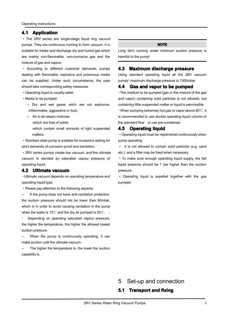
Fig. 3 Mechanical structure of 2RV2/2RV5 series
1. Pump cover
2. Separating plate
3. Flat key
4. Impeller
5. Mechanical seal
6. Pump casing
7. Driving motor
3333....3333....3333 2222BBBRVVVV6666 sssseeeerrrriiiieeeessss
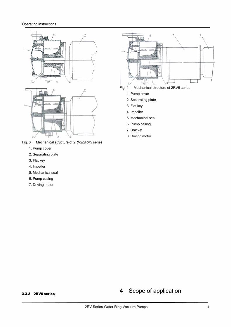
Fig. 4 Mechanical structure of 2RV6 series
1. Pump cover
2. Separating plate
3. Flat key
4. Impeller
5. Mechanical seal
6. Pump casing
7. Bracket
8. Driving motor
4 Scope of application
Operating Instructions
2RV Series Water Ring Vacuum Pumps 5
4.14.14.14.1 ApplicationApplicationApplicationApplication· The 2RV series are single-stage liquid ring vacuum
pumps. They are continuous running to form vacuum. It is
suitable for intake and discharge dry and humid gas which
are mainly non-flammable, non-corrosive gas and the
mixture of gas and vapour.
· According to different customer demands, pumps
dealing with flammable, explosive and poisonous media
can be supplied. Under such circumstance, the user
should take corresponding safety measures.
·Operating liquid is usually water.
·Media to be pumped:
-- Dry and wet gases witch are not explosive,
inflammable, aggressive or toxic
-- Air or air-steam mixtures
-which are free of solids
-which contain small amounts of light suspended
matters.
·Stainless steel pump is suitable for occasions asking for
strict demands of corrosion-proof and sanitation.
·2RV series pumps create low vacuum, and the ultimate
vacuum is decided by saturated vapour pressure of
operating liquid.
4.24.24.24.2 UltimateUltimateUltimateUltimate vacuumvacuumvacuumvacuum·Ultimate vacuum depends on operating temperature and
operating liquid type.
·Please pay attention to the following aspects:
-- If the pump does not have anti-cavitation protection,
the suction pressure should not be lower than 80mbar,
which is in order to avoid causing cavitation in the pump
when the water is 15℃ and the dry air pumped is 20℃. -
- Depending on operating saturated vapour pressure,
the higher the temperature, the higher the allowed lowest
suction pressure.
-- When the pump is continuously operating, it can
make suction until the ultimate vacuum.
-- The higher the temperature is, the lower the suction
capability is.
NOTENOTENOTENOTE
Long term running under minimum suction pressure is
harmful to the pump!
4.34.34.34.3 MaximumMaximumMaximumMaximum dischargedischargedischargedischarge pressurepressurepressurepressureUsing standard operating liquid all the 2BV vacuum
pumps’ maximum discharge pressure is 1300mbar.
4.44.44.44.4 GasGasGasGas andandandand vaporvaporvaporvapor totototo bebebebe pumpedpumpedpumpedpumped·The medium to be pumped (gas or the mixture of the gas
and vapor) containing solid particles is not allowed, but
containing little suspended matter or liquid is permissible.
·When pumping extremely hot gas or vapor above 80℃, it
is recommended to use double operating liquid volume of
the standard flow or use pre-condenser.
4.54.54.54.5 OperatingOperatingOperatingOperating liquidliquidliquidliquid·Operating liquid must be replenished continuously when
pump operating.
· It is not allowed to contain solid particles (e.g. sand
etc.), and a filter may be fixed when necessary.
·To make sure enough operating liquid supply, the fed
liquid pressure should be 1 bar higher than the suction
pressure.
· Operating liquid is expelled together with the gas
pumped.
5 Set-up and connection5.15.15.15.1 TransportTransportTransportTransport andandandand fixingfixingfixingfixing

Operating Instructions
2RV Series Water Ring Vacuum Pumps 6
·2RV vacuum pump is installed horizontally on surface,
and mounted with foundation bolts through bolt holes,
(without base frame).
· When slinging and transporting the pump, it is
recommended to hook both the sling bolt on the motor
and the bolt hole in the suction flange.
Fig. 5 Lifting the pump
WARNINGWARNINGWARNINGWARNING
Risk of death or contusions from falling goods to be
transported!
-- Select lifting gear in accordance with the total weight
to be transported.
-- Transport the pump in horizontal position only.
-- Do not stand under suspended loads.
5.25.25.25.2 PipePipePipePipe connectionconnectionconnectionconnection·To avoid foreign particle entering the pump, protecting
covers are added to all connection openings when
delivery and do not remove them before pipe connection
completed.
·The connection of pipes should not produce stress andsupports should be added on pipes.
5555....2222....1111 DDDDiiiisssscccchhhhaaaarrrrggggeeee ppppoooorrrrtttt ffffllllaaaannnnggggeeee2RV-E161: Flange 80ND 10-DIN
2501, Seal 80ND 6 DIN 2690;
2RV-E131/2RV-E121:
Flange 65ND 10-DIN 2501,
Seal 65ND 6 DIN 2690;
2RV-E110/2RE110:
Flange 50ND 10-DIN 2501,
Seal 50ND 6 DIN 2690;
5555....2222....2222 SSSSuuuuccccttttiiiioooonnnn ppppoooorrrrtttt ffffllllaaaannnnggggeeee
Similar to the discharge port flange, in order to prevent the
fixing residue dropping in, e.g. welding slag, it is
recommended to install a filter to the suction pipe in the
initial 100 hours.
Fig. 6 Pipe connection of cast iron material pump
1. Discharge port
2. Suction port
3. Anti-cavitations connection 3/8
4. Operating liquid connection 3/4
5. Water drainage 3/8
Fig. 7 Pipe connection of stainless steel material pump
1. Discharge port
2. Suction port
3. Anti-cavitation connection
4. Operating liquid connection 3/4
Flange connection DN15
5. Water drainage 3/8
5.2.35.2.35.2.35.2.3 TheTheTheThe recommendedrecommendedrecommendedrecommended modemodemodemode ofofofof thethethethe operatingoperatingoperatingoperating
liquidliquidliquidliquid connectionconnectionconnectionconnection
Operating Instructions
2RV Series Water Ring Vacuum Pumps 7
Fig. 8 Example of operating liquid connection
1. 2RV vacuum pump
15. Flow meter (optional)
16. Control valve
17. Solenoid valve (controlled by driving motor)
(motor starts up-the valve open)
(motor shuts down- valve close)
18. Bypass pipe globe valve
19. Filter (optional)
20. Feed pipe for operating liquid
5555....3333 SSSSuuuuppppppppllllyyyy mmmmooooddddeeee ooooffff ooooppppeeeerrrraaaattttiiiinnnngggg lllliiiiqqqquuuuiiiiddddIt is a connection to make sure enough operating liquid
supply, thus to guarantee minimum suction pressure. The
discharged liquid is expelled completely and meanwhile
flesh operating liquid replenished.
After filled with water in advance, 2RV vacuum pump can
work in the state of automatic water replenishing. Thus,
make sure operating liquid to a certain level when staring
the pump.
A. Operating liquid B. Operating liquid circulating
circulating pipeline pipeline (with separator)
Fig. 9 Supply mode of operating liquid
1. 2RV vacuum pump 2.Suction pipe
3. Vent valve (solenoid valve) 4. Check valve
6. Separator 7. Overflow port
12. Outlet pipe for operating liquid
20. Feed pipe of operating liquid
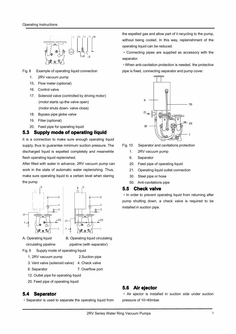
5.45.45.45.4 SeparatorSeparatorSeparatorSeparator·Separator is used to separate the operating liquid from
the expelled gas and allow part of it recycling to the pump,
without being cooled. In this way, replenishment of the
operating liquid can be reduced.
·Connecting pipes are supplied as accessory with the
separator.
·When anti-cavitation protection is needed, the protective
pipe is fixed, connecting separator and pump cover.
Fig. 10 Separator and cavitations protection
1. 2RV vacuum pump
6. Separator
20. Feed pipe of operating liquid
21. Operating liquid outlet connection
30. Steel pipe or hose
50. Anti-cavitations pipe
5.55.55.55.5 CheckCheckCheckCheck valvevalvevalvevalve·In order to prevent operating liquid from returning after
pump shutting down, a check valve is required to be
installed in suction pipe.
5.65.65.65.6 AirAirAirAir ejectorejectorejectorejector· Air ejector is installed in suction side under suction
pressure of 10~40mbar.
Operating Instructions
2RV Series Water Ring Vacuum Pumps 8
· It can obtain 10mbar vacuum by adding an air ejector
and will not increase power consumption.
· The seal gasket should be concentric with the
connection pipe in order to avoid running area reducing.
·The air ejector may function as restriction choke when
pumping container in pressure between 1000 and
100mbar.
NOTENOTENOTENOTE
The ejected gas (20℃, 1013mbar atmosphere) cannot
contain any water drop.
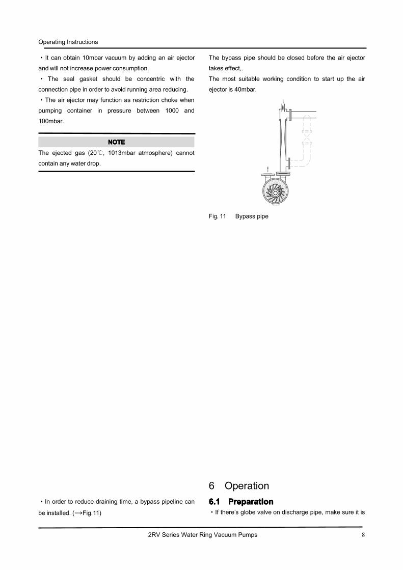
·In order to reduce draining time, a bypass pipeline can
be installed. (→Fig.11)
The bypass pipe should be closed before the air ejector
takes effect,.
The most suitable working condition to start up the air
ejector is 40mbar.
Fig. 11 Bypass pipe
6 Operation6.16.16.16.1 PreparationPreparationPreparationPreparation·If there’s globe valve on discharge pipe, make sure it is

Operating Instructions
2RV Series Water Ring Vacuum Pumps 9
open when pump starting up or shutting down.
WARNINGWARNINGWARNINGWARNING
Risk of material damage caused by dry running!
·Before operating, fill in the pump in advance via suctionport or discharge port.
-- Fill 2RV-E161 with 8 liter operating flow in advance; --
Fill 2RV-E131/121/111/110 with 3 liter operating flow in
advance.
or :
-- open the bypass valve about 20 seconds to ensure
operating liquid flowing into the pump (→ Fig8, Page6). Inspect discharge pipe and operating liquid supply pipe to
make sure the connection in good condition.
·Start up the pump instantly to check its rotating direction.
The gas in and out direction and the pump shaft rotating
direction are labeled as arrows on the pump.
·Compare the rotating direction of the motor fan and the
arrow direction on the back of the pump casing. If
necessary, the rotating direction of the motor can be
changed by changing the two wires.
6.26.26.26.2 StartingStartingStartingStarting upupupup andandandand shuttingshuttingshuttingshutting downdowndowndown·Start up the pump and check operating liquid flow. If
necessary, regulate liquid flow by the control valve
(→Fig8, 16). Volume flow meter (→Fig8.15) is used toobtain standard operating liquid flow.
· If the pump needs to be controlled automatically
(installed as Fig8 showing), the operating liquid flow is
controlled by solenoid valve(→Fig 8.17) which isgoverned by motor.
Pump operating ----valve opens
Pump shutdown ---- valve closes
· If the pump is not automatically controlled, followingsteps should be adopted:
-- Start up: start up the pump and then open the globe
valve (→Fig 8.17) rapidly.
-- Shut down: close globe valve (→Fig 8.17), and stop the pump rapidly.When the 2RV vacuum pump stops operating, the control
valve (→Fig 8.16) is closed.
WARNINGWARNINGWARNINGWARNING
Risk of injuries caused by vacuum or harmful media to be
pumped and operating liquid!
DANGERDANGERDANGERDANGER
Risk of injuries caused by running pump andmotor!
-- Do not touch the running pump
6.36.36.36.3 DrainingDrainingDrainingDraining offoffoffoff
WARNINGWARNINGWARNINGWARNING
If the operating liquid is harmful to human body or
environment, for the sake of safety, the pump needs to be
flushed during operation, before unscrewing the bolt to
drain off.
·To drain off, unscrew the bolt on the pump cover to let
the liquid flow out. Meanwhile, turn round the pump by
twirling the fan by hand until no liquid flow out.·The pump can be drained off by making the pump cover
45℃ inclination. In this way the pump can be kept
shutdown for a long time or in cold climate, without
causing damage to the pump.
7 Maintenance7.17.17.17.1 FlushFlushFlushFlush thethethethe pumppumppumppump
·To avoid impeller and pump casing wearing or impeller
blocking, the dust particle entering the pump chamber
with the gas and operating liquid should be flushed out

Operating Instructions
2RV Series Water Ring Vacuum Pumps 10
via the flushing port in the lower part on the pump cover.
· If hard water is used as operating liquid, it should be
softened, or flush the pump with solvent regularly.
7.27.27.27.2 LubricationLubricationLubricationLubrication· When using 50Hz motor under normal working
conditions:
-- After operating 20000 hours or 3 years at most, clear
off the dirt and the discarded grease near the shaft and
then replenish with fresh grease.
-- The grease replenished should occupy 50% of the
shaft free space and 65% of the bearing cup.
NOTENOTENOTENOTE
Collect contamination and escaping operating liquid and
dispose of in an environmentally-compatible way.
· If the working condition is extremely bad, the
replacement period of the grease should be
correspondingly shortened.
7.37.37.37.3 StorageStorageStorageStorage·If kept shutdown for about 4 weeks, the pump should be
drained off completely in advance. Later it needs to carry
on anticorrosive treatment, that is to pour 1/2 liter
anticorrosive oil into the pump through the suction port or
the discharge port and operate the pump for a short time.
· If the impeller is blocked when keeping prolonged
storage after using hard water, the pump chamber should
be filled with 10% oxalic acid and keeps for about 30
minutes.
· Make sure the storage room meets the following
conditions:
-- dry
-- frost-free
-- protected
-- constant humidity
7.47.47.47.4 TroubleshootingTroubleshootingTroubleshootingTroubleshooting
DefectDefectDefectDefect CauseCauseCauseCause RectificationRectificationRectificationRectification
Insufficient suction
capacity
1. Excessive gap between impeller
and inter casing.
Adjust for a correct gap
2. Air leakage of the packing Tighten or replace the packing, lower the water
supply temperature
3. Hot temperature of the water ring Increase operating liquid flow rate
4. Leakage in pipeline Tighten flange blots, replace gasket, weld the
crackles
5. Excessive flow resistance in
suction pipe
Reduce elbows, replace thick pipes
Insufficient vacuum A. Pipeline
1. Leakage in flange connection Tighten flange blots/replace gaskets
2. Crackle on pipes Weld the crackles/ replace pipe
B. Water ring
1. Air leakage of the packing Tighten or replace the packing
2. Excessive gap size between
impeller and side cap
Replace gasket, adjust the gap
DefectDefectDefectDefect CauseCauseCauseCause RectificationRectificationRectificationRectification
3. Operating liquid to got Cool down the operating liquid

Operating Instructions
2RV Series Water Ring Vacuum Pumps 11
Tab. 1 Defect, cause and solutions
8 Technical data8.18.18.18.1 TechnicalTechnicalTechnicalTechnical datadatadatadata ((((380V380V380V380V 50HZ50HZ50HZ50HZ))))8.1.18.1.18.1.18.1.1 TechnicalTechnicalTechnicalTechnical parameterparameterparameterparameter
4. Insufficient operating liquid flow
rate
Increase operating liquid flow rate
5. Hot operating liquid caused by
components friction
Adjust/ reassemble
Vibration or
strange noise
1. Loose foundation bolts Tighten foundation bolts
2. Foreign body grinds in the pump Shut down the pump and clear the foreign body.
3. Loose impeller Replace the impeller
4. Cavitation Open the valve of suction pipe
5. Bearing damage Replace the bearing
Bearing too hot
1. Insufficient lubrication Grease the bearing
2. Packing too tight Properly loosen the gland cover
3. No or insufficient sealing water
supply
Supply sealing water/Increase
4. Tight joint between bearing, shaft
or bearing bracket lead to small
gap and friction among balls and
inner ring
Readjust the joints between bearing and shaft/
bearing bracket
5. Bearing damage Replace the bearing
Hard startup
1. Rustiness owing to long-term
halt
Rotate the shaft towards the direction of pump
rotation.
2. Packing too tight Properly loosen the gland cover
3. Impeller rubs against the pump
casing.
Disassemble the pump, properly set the gap
size between impeller and pump casing
Leakage of
mechanical seal
1. Worn-out mechanical seal Replace mechanical seal
2. Loose spring of mechanical seal Adjust the elasticity of spring
3. Worn-out “O”-ring Replace the “O”-ring
Sudden shut down 1. Axial rotation of impeller Tighten the impeller
2. Pump is blocked by foreign body Clear the foreign body

Operating Instructions
2RV Series Water Ring Vacuum Pumps 12
Tab. 2 Technical parameter of 380V,50HZ condition
The data above is obtained in condition of:
-- saturated air temperature of media pumped: 20℃,
-- operating liquid temperature: 15℃,
-- discharge pressure: 1013mbar
-- allowance factor ±10%.
8.1.28.1.28.1.28.1.2 PerformancePerformancePerformancePerformance curvecurvecurvecurve
CurveCurveCurveCurve
No.No.No.No.
ModelModelModelModel Max.Max.Max.Max. suctionsuctionsuctionsuction
capacitycapacitycapacitycapacity
UltimateUltimateUltimateUltimate
vacuumvacuumvacuumvacuum
mbar(MPa)
MotorMotorMotorMotor
powerpowerpowerpower
kW
MotorMotorMotorMotor
explosion-proofexplosion-proofexplosion-proofexplosion-proof
gradegradegradegrade
MotorMotorMotorMotor
protectionprotectionprotectionprotection
gradegradegradegrade
SpeedSpeedSpeedSpeed
r.p.m
OperatingOperatingOperatingOperating
liquidliquidliquidliquid
flowflowflowflow raterateraterate
L/min
NoiseNoiseNoiseNoise
dB(A)
WeightWeightWeightWeight
kgm3/min m3/h
60V 2RV2-060 0.45 27
33mbar
(-0.097MPa)
0.81
Non-explosion
proof
IP54
2840 2.5 62 37
61V 2RV2-061 0.86 52 1.45 2840 2.5 65 41
70V 2RV2-070 1.33 80 2.35 2860 3 66 66
71V 2RV2-071 1.83 110 3.85 2880 4.7 72 85
110V 2RV5-110 2.75 165 4
Non-explosion
proof
1440 7.2 63 120
111V 2RV5-111 3.83 230 5.5 1440 8.8 68 150
121V 2RV5-121 4.66 280 7.5 1440 11 69 210
131V 2RV5-131 6.66 400 11 1460 16 73 280
161V 2RV5-161 8.33 500 15 970 22 74 390
110V 2RV6-110 2.75 165 4
dIIBT4 IP55
1440 67 63 150
111V 2RV6-111 3.83 230 5.5 1440 10 68 200
121V 2RV6-121 4.66 280 7.5 1440 12 69 230
131V 2RV6-131 6.66 400 11 1460 17 73 315
161V 2RV6-161 8.33 500 15 970 23 74 426
Operating Instructions
2RV Series Water Ring Vacuum Pumps 13
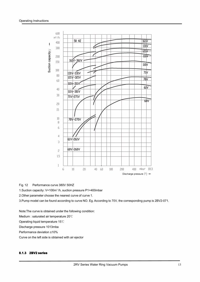
Fig. 12 Performance curve 380V 50HZ
1.Suction capacity: V=100m³/h, suction pressure P1=400mbar
2.Other parameter choose the nearest curve of curve 1.
3.Pump model can be found according to curve NO. Eg. According to 70V, the corresponding pump is 2BV2-071.
Note:The curve is obtained under the following condition:
Medium : saturated air temperature 20℃
Operating liquid temperature 15℃
Discharge pressure 1013mba
Performance deviation ±10%
Curve on the left side is obtained with air ejector
8888....1111....3333 2222BBBRVVVV2222 sssseeeerrrriiiieeeessss

Operating Instructions
2RV Series Water Ring Vacuum Pumps 14
Fig. 13 Dimension of 2RV-2060/2061/2070/2071
N1.0 Suction port
N2.0 Discharge port
N3.0 Operating liquid connection
N4.2 Water outlet
N8.7 Anti-cavitations connection
Tab. 3
8888....1111....4444 2222BBBRVVVV5555 sssseeeerrrriiiieeeessss
A B B1 H1 H2 H3 H4 H6 E P2 P3 R M S2 W1 W2 W3 d N3.0 N4.2 N8.7
2060 455 186 140 90 118 126 195 37.5 100 250 180 217 244 Φ10 110 26 21 G1″ G3/8″ G1/4″ G3/8″
2061 476 186 140 90 118 195 195 37.5 100 250 180 236 263 Φ10 110 26 21 G1″ G3/8″ G1/4″ G3/8″
2070 545 223 160 222 100 128 222 33 140 270 203 252 280 Φ12 110 33 27G1 ″
G3/8″ G1/4″ G3/8″
2071 566 223 234 140 112 140 234 45 190 300 225 278 309 Φ12 110 33 37G1 ″
G3/8″ G1/4″ G3/8″

Operating Instructions
2RV Series Water Ring Vacuum Pumps 15
Fig. 14 Dimension of 2RV-5110/5111/5121/5131/5161
N1.0 Suction port
N2.0 Discharge port
N3.0 Operating liquid connection
N4.2 Water outlet
N8.7 Anti-cavitations connection

Operating Instructions
2RV Series Water Ring Vacuum Pumps 16
Tab. 4
Tab. 5
8888....1111....5555 2222BBBRVVVV6666 sssseeeerrrriiiieeeessss
A B B1 B2 C1 C2 H1 H2 H3 H4 H5 H6 H7 F K L N T S1 S2 d1 d2 d3 d4 d5 W1
5110 637 325 255 190 41 26 140 156 202 361 328 38 57 464 320 130 92 340 Φ12Φ12 19 160 123 97 52 180
5111 672 325 265 290 38 26 150 166 212 371 363 48 68 500 325 130 92 340 Φ12Φ12 19 160 123 97 52 180
5121 771 347 265 290 36 26 150 167 217 385 363 39 60 584 410 147 97 382 Φ12Φ12 19 182 142 113 67 200
5131 840 377 300 335 35 30 175 194 249 427 435 53 76 659 440 147 103 382 Φ12Φ12 19 182 142 113 67 200
5161 1044 479 370 389 52 30 210 225 303 521 485 51 80 808 570 201 138 450 Φ15Φ15 22 200 156 130 80 250
W2 W3 d(N1.0,N2.0) N3.0 N4.2 N8.7
5110 52 27 DN50/2″ G3/4″(length24) G3/8″(length 25) G3/8″(length 11)
5111 52 27 DN50/2″ G3/4″(length 24) G3/8″(length 25) G3/8″(length 11)
5121 57 29 DN65/2″ G3/4″(length 24) G3/8″(length 25) G3/8″(length 11)
5131 63 32 DN65/2″ G3/4″(length 24) G3/8″(length 25) G3/8″(length 11)
5161 81 41 DN80/3″ G3/4″(length 24) G3/8″(length 25) G3/8″(length 11)
Operating Instructions
2RV Series Water Ring Vacuum Pumps 17
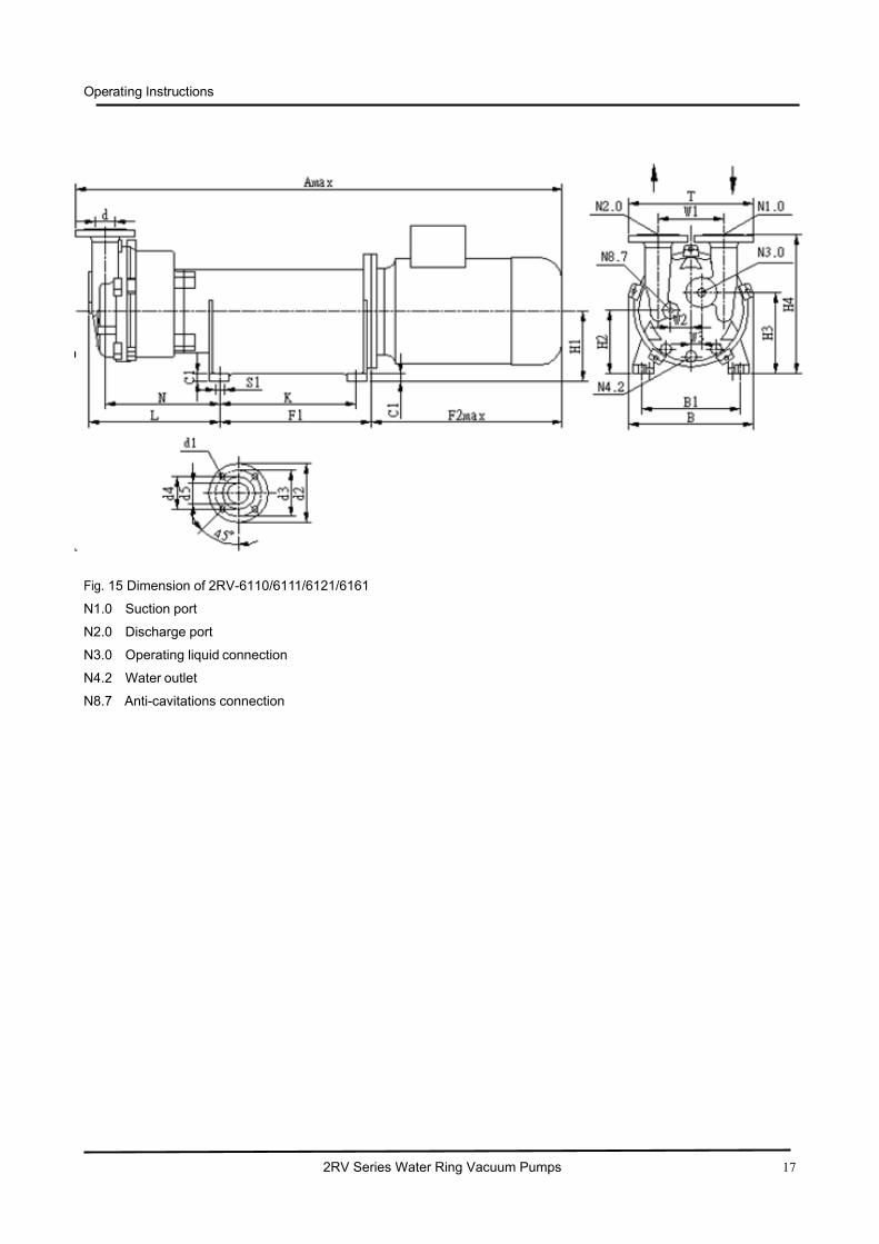
Fig. 15 Dimension of 2RV-6110/6111/6121/6161
N1.0 Suction port
N2.0 Discharge port
N3.0 Operating liquid connection
N4.2 Water outlet
N8.7 Anti-cavitations connection

Operating Instructions
2RV Series Water Ring Vacuum Pumps 18
Tab. 6
8.28.28.28.2 TechnicalTechnicalTechnicalTechnical datadatadatadata (380V380V380V380V 60HZ60HZ60HZ60HZ)
Amax B B1 C1 F1 F2max H1 H2 H3 H4 H6 H7 K L N
6110 1097 330 255 26 291 490 160 173 223 381 58 77 319 319 281
6111 1291 330 279 26 360 550 180 196 242 401 78 97 349 349 311
6121 1332 351 279 26 361 605 180 197 247 415 69 90 384 384 340
6131 1525 382 320 26 461 615 215 234 287 467 93 116 405 405 353
6161 1680 484 320 26 461 705 230 230 310 526 56 85 477 477 413
W1 W2W3 S1 T d1 d2 d3 d4 d5d(N1.0,
N2.0)N3.0 N4.2 N8.7
6110 180 52 27 Φ13×23 340 19 160 123 97 52 DN50/2″″DN15+G3/4″
(length 24)
G3/8″
(length 25)
G3/8″
(length 11)
6110 80 52 27 Φ13×23 340 19 160 123 97 52 DN50/2″″DN15+G3/4″
(length 24)
G3/8″
(length 25)
G3/8″
(length 11)
6121 200 57 29 Φ13×23 382 19 182 142 113 67 DN60/21/2″″DN15+G3/4″
(length24)
G3/8″
(length 25)
G3/8″
(length 11)
6131 200 63 29 Φ13×27 382 19 182 142 113 67 DN60/21/2″″DN15+G3/4″
(length 24)
G3/8″
(length 25)
G3/8″
(length 11)
6161 250 81 41 Φ13×27 450 22 200 156 130 80 DN80/3″″DN15+G3/4″
(length 24)
G3/8″(length
25)
G3/8″
(length 11)

Operating Instructions
2RV Series Water Ring Vacuum Pumps 19
8.2.18.2.18.2.18.2.1 TechnicalTechnicalTechnicalTechnical parameterparameterparameterparameter
Tab. 7
8.2.28.2.28.2.28.2.2 PerformancePerformancePerformancePerformance curvecurvecurvecurve
CurveCurveCurveCurve
No.No.No.No.
ModelModelModelModel Max.Max.Max.Max. suctionsuctionsuctionsuction
capacitycapacitycapacitycapacity
UltimateUltimateUltimateUltimate
vacuumvacuumvacuumvacuum
mbar(MPa)
MotorMotorMotorMotor
powerpowerpowerpower
kW
MotorMotorMotorMotor
explosion-explosion-explosion-explosion-
proofproofproofproof gradegradegradegrade
MotorMotorMotorMotor
protectionprotectionprotectionprotection
gradegradegradegrade
SpeedSpeedSpeedSpeed
r.p.m
OperatingOperatingOperatingOperating
liquidliquidliquidliquid flowflowflowflow
raterateraterate L/min
NoiseNoiseNoiseNoise
dB(A)m3/min m3/h
60V 2RVN-060 0.5 30
33mbar
(-0.097MPa)
1.5Non-explosion
proof /
explosion proof
IP54
3450 4.5 63
61V 2RVN-061 0.97 58 3 3450 4.5 66
70V 2RVN-070 1.46 88 4 3450 5 68
71V 2RVN-071 2.05 123 5.5 3450 6 72
110V 2RVN-110 3.08 185 7.5
Non-explosion
proof /
explosion proof
1745 9 63
111V 2RVN-111 4.3 258 7.5 1745 12 68
121V 2RVN-121 5.23 313 11 1745 15 69
131V 2RVN-131 7.33 440 15 1745 18 73
161V 2RVN-161 9.33 560 18.5 1175 24 74

Operating Instructions
2RV Series Water Ring Vacuum Pumps 20
Fig. 16 Performance curve 380V 60HZ
The curve is obtained in 60HZ motor frequency.
Broadband motor range 30-60HZ
Variable torque speed 30-50HZ
Constant power speed 50-60HZ
8888....2222....3333 2222BBBRVVVVNNNN----000066660000////000066661111////000077770000////000077771111 ((((wwwwiiiitttthhhh eeeexxxxpppplllloooossssiiiioooonnnn----pppprrrrooooooooffff mmmmoooottttoooorrrr ))))
Operating Instructions
2RV Series Water Ring Vacuum Pumps 21
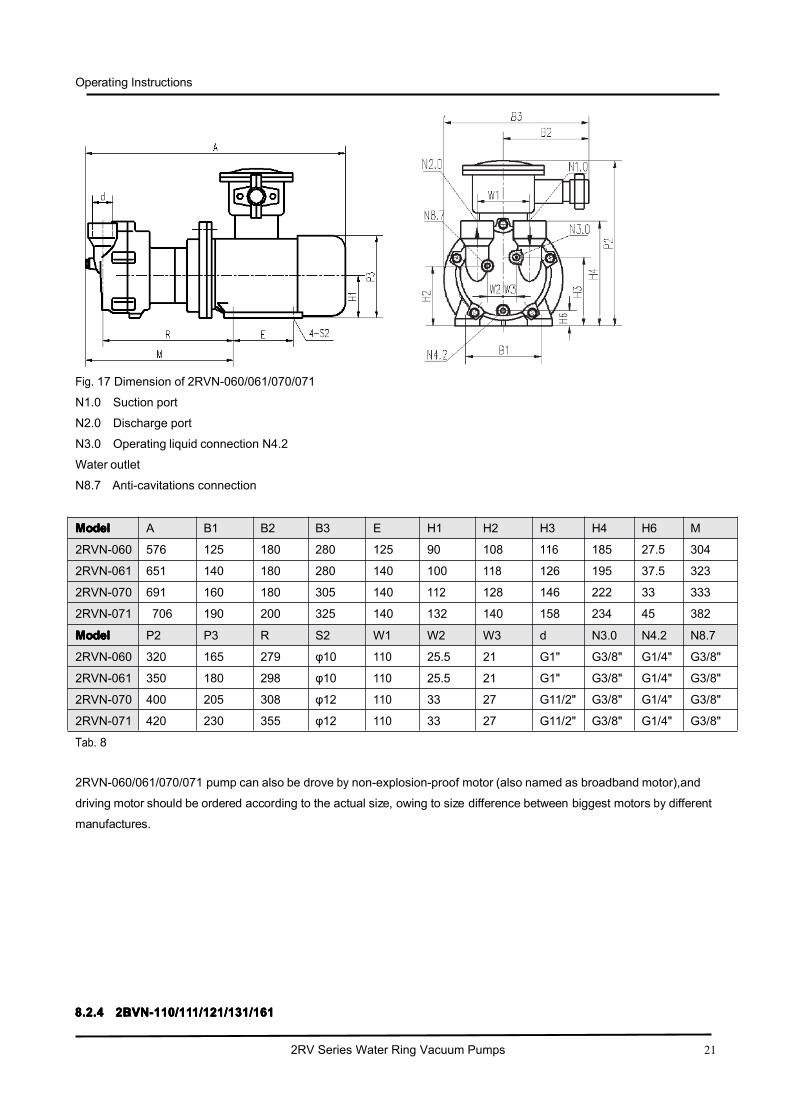
Fig. 17 Dimension of 2RVN-060/061/070/071
N1.0 Suction port
N2.0 Discharge port
N3.0 Operating liquid connection N4.2
Water outlet
N8.7 Anti-cavitations connection
Tab. 8
2RVN-060/061/070/071 pump can also be drove by non-explosion-proof motor (also named as broadband motor),and
driving motor should be ordered according to the actual size, owing to size difference between biggest motors by different
manufactures.
8888....2222....4444 2222BBBRVVVVNNNN----111111110000////111111111111////111122221111////111133331111////111166661111
ModelModelModelModel A B1 B2 B3 E H1 H2 H3 H4 H6 M
2RVN-060 576 125 180 280 125 90 108 116 185 27.5 304
2RVN-061 651 140 180 280 140 100 118 126 195 37.5 323
2RVN-070 691 160 180 305 140 112 128 146 222 33 333
2RVN-071 706 190 200 325 140 132 140 158 234 45 382
ModelModelModelModel P2 P3 R S2 W1 W2 W3 d N3.0 N4.2 N8.7
2RVN-060 320 165 279 φ10 110 25.5 21 G1" G3/8" G1/4" G3/8"
2RVN-061 350 180 298 φ10 110 25.5 21 G1" G3/8" G1/4" G3/8"
2RVN-070 400 205 308 φ12 110 33 27 G11/2" G3/8" G1/4" G3/8"
2RVN-071 420 230 355 φ12 110 33 27 G11/2" G3/8" G1/4" G3/8"
Operating Instructions
2RV Series Water Ring Vacuum Pumps 22
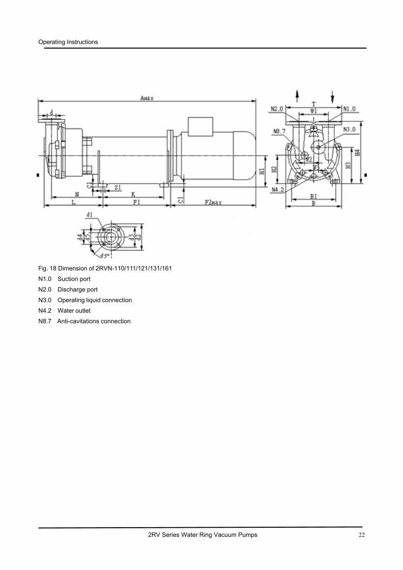
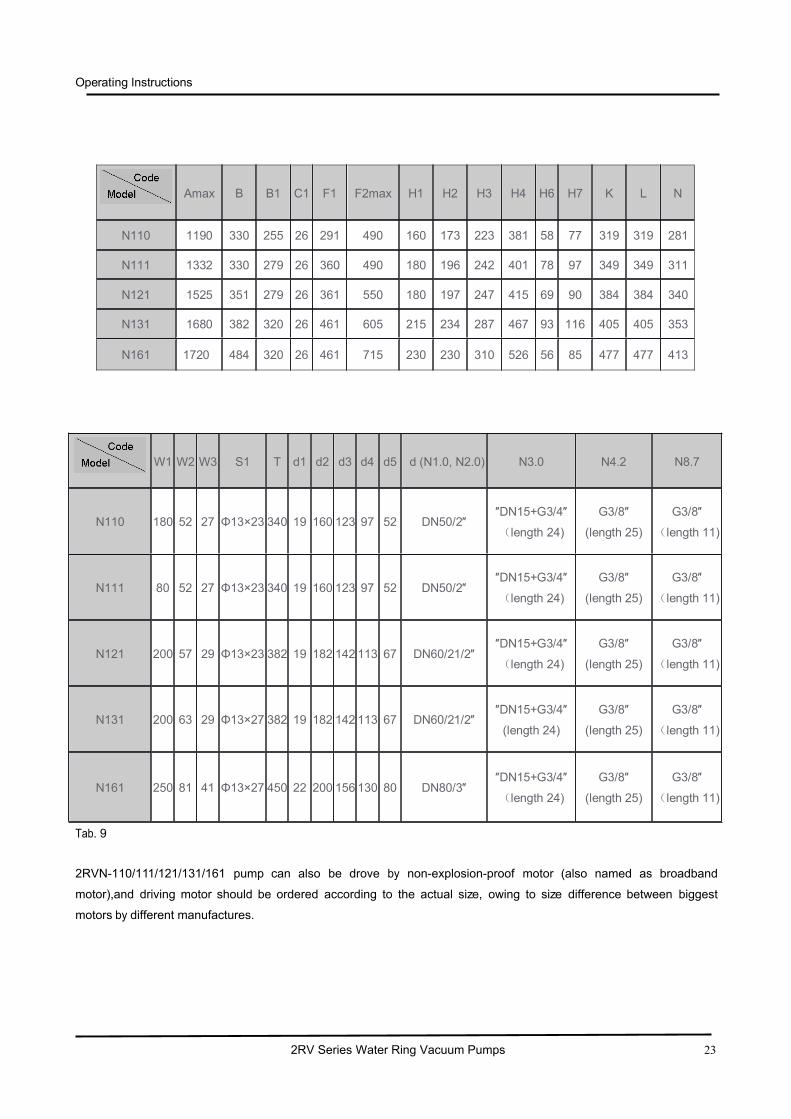
Fig. 18 Dimension of 2RVN-110/111/121/131/161
N1.0 Suction port
N2.0 Discharge port
N3.0 Operating liquid connection
N4.2 Water outlet
N8.7 Anti-cavitations connection
Operating Instructions
2RV Series Water Ring Vacuum Pumps 23
Tab. 9
2RVN-110/111/121/131/161 pump can also be drove by non-explosion-proof motor (also named as broadband
motor),and driving motor should be ordered according to the actual size, owing to size difference between biggest
motors by different manufactures.
Amax B B1 C1 F1 F2max H1 H2 H3 H4 H6 H7 K L N
N110 1190 330 255 26 291 490 160 173 223 381 58 77 319 319 281
N111 1332 330 279 26 360 490 180 196 242 401 78 97 349 349 311
N121 1525 351 279 26 361 550 180 197 247 415 69 90 384 384 340
N131 1680 382 320 26 461 605 215 234 287 467 93 116 405 405 353
N161 1720 484 320 26 461 715 230 230 310 526 56 85 477 477 413
W1 W2 W3 S1 T d1 d2 d3 d4 d5 d (N1.0, N2.0) N3.0 N4.2 N8.7
N110 180 52 27 Φ13×23 340 19 160 123 97 52 DN50/2″″DN15+G3/4″
(length 24)
G3/8″
(length 25)
G3/8″
(length 11)
N111 80 52 27 Φ13×23 340 19 160 123 97 52 DN50/2″″DN15+G3/4″
(length 24)
G3/8″
(length 25)
G3/8″
(length 11)
N121 200 57 29 Φ13×23 382 19 182 142 113 67 DN60/21/2″″DN15+G3/4″
(length 24)
G3/8″
(length 25)
G3/8″
(length 11)
N131 200 63 29 Φ13×27 382 19 182 142 113 67 DN60/21/2″″DN15+G3/4″
(length 24)
G3/8″
(length 25)
G3/8″
(length 11)
N161 250 81 41 Φ13×27 450 22 200 156 130 80 DN80/3″″DN15+G3/4″
(length 24)
G3/8″
(length 25)
G3/8″
(length 11)
Operating Instructions
2RV Series Water Ring Vacuum Pumps 24
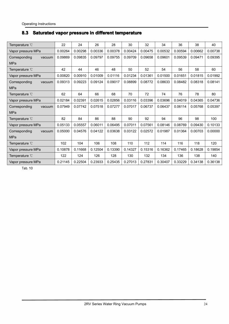
8.38.38.38.3 SaturatedSaturatedSaturatedSaturated vaporvaporvaporvapor pressurepressurepressurepressure inininin differentdifferentdifferentdifferent temperaturetemperaturetemperaturetemperature
Tab. 10
Temperature℃ 22 24 26 28 30 32 34 36 38 40
Vapor pressure MPa 0.00264 0.00298 0.00336 0.00378 0.00424 0.00475 0.00532 0.00594 0.00662 0.00738
Corresponding vacuum
MPa
0.09869 0.09835 0.09797 0.09755 0.09709 0.09658 0.09601 0.09539 0.09471 0.09395
Temperature℃ 42 44 46 48 50 52 54 56 58 60
Vapor pressure MPa 0.00820 0.00910 0.01009 0.01116 0.01234 0.01361 0.01500 0.01651 0.01815 0.01992
Corresponding vacuum
MPa
0.09313 0.09223 0.09124 0.09017 0.08899 0.08772 0.08633 0.08482 0.08318 0.08141
Temperature℃ 62 64 66 68 70 72 74 76 78 80
Vapor pressure MPa 0.02184 0.02391 0.02615 0.02856 0.03116 0.03396 0.03696 0.04019 0.04365 0.04736
Corresponding vacuum
MPa
0.07949 0.07742 0.07518 0.07277 0.07017 0.06737 0.06437 0.06114 0.05768 0.05397
Temperature℃ 82 84 86 88 90 92 94 96 98 100
Vapor pressure MPa 0.05133 0.05557 0.06011 0.06495 0.07011 0.07561 0.08146 0.08769 0.09430 0.10133
Corresponding vacuum
MPa
0.05000 0.04576 0.04122 0.03638 0.03122 0.02572 0.01987 0.01364 0.00703 0.00000
Temperature℃ 102 104 106 108 110 112 114 116 118 120
Vapor pressure MPa 0.10878 0.11668 0.12504 0.13390 0.14327 0.15316 0.16362 0.17465 0.18628 0.19854
Temperature℃ 122 124 126 128 130 132 134 136 138 140
Vapor pressure MPa 0.21145 0.22504 0.23933 0.25435 0.27013 0.27831 0.30407 0.33229 0.34138 0.36138

Operating Instructions
2RV Series Water Ring Vacuum Pumps 25