remedial cutoff walls for dams in the u.s.: 40 years of ... - remedial cut-off walls for... ·...
TRANSCRIPT

– 1 –
Remedial Cutoff Walls for Dams in the U.S.:
40 Years of Case Histories
Donald A. Bruce1
1 Geosystems, L.P., P.O. Box 237, Venetia, PA 15367; e-mail: [email protected]
ABSTRACT
Since 1975, there has been a rich history of embankment dam remediation in the U.S., mostly to
prevent seepage and erosion through and under these structures. The history of these works has
been described by many authors, the compendium of Bruce (2012) being the most recent,
addressing projects completed up to 2010. Since then, a number of extremely large remediations
have been completed, including cutoffs at Clearwater, Wolf Creek, Center Hill, Pine Creek,
Bolivar Dams, and Herbert Hoover Dike. Together these more recent projects greatly exceed the
combined cost of similar works conducted in the prior 35 years. This paper provides an updated
compendium of these projects, and provides detailed references for future researchers to develop.
1. INTRODUCTION
The National Inventory of Dams (NID) has listed over 84,000 dams in the United States which
meet its criteria for inclusion (Ragon, 2011), namely:
1. High hazard classification — loss of one human life is likely if the dam fails.
2. Significant hazard classification — possible loss of human life and likely significant
property or environmental destruction.
3. Low hazard classification — no probable loss of human life and low economic and/or
environmental losses, but the dam:
equals or exceeds 25 feet in height and exceeds 15 acre-feet in storage;
equals or exceeds 50 acre-feet storage and exceeds 5 feet in height.
Almost 14,000 dams meet Criterion 1. Only 4% (3,075) are federally owned, and these
mainly date from the earlier third of the Twentieth Century. Over 87% of the total are primarily
classified as earth embankments, while no other category exceeds 3% of the total. The main
primary purposes are recreation (35%), flood control (17%), fire protection in stock/small fish
ponds (15%) and irrigation (10%), while less than 3% generate power. Many structures are
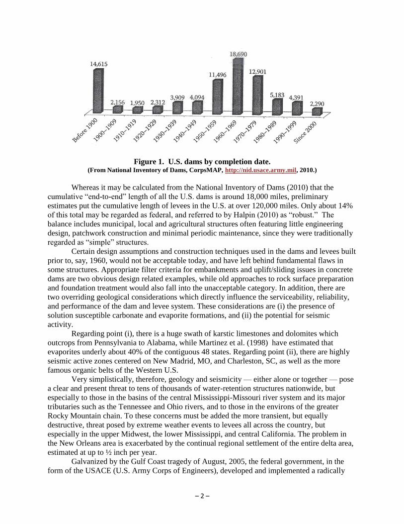
multipurpose. Figure 1 summarizes their completion dates: about 50% were completed between
1950 and 1979, while the median age in the year 2016 is about 65 years.
– 2 –
Figure 1. U.S. dams by completion date. (From National Inventory of Dams, CorpsMAP, http://nid.usace.army.mil, 2010.)
Whereas it may be calculated from the National Inventory of Dams (2010) that the
cumulative “end-to-end” length of all the U.S. dams is around 18,000 miles, preliminary
estimates put the cumulative length of levees in the U.S. at over 120,000 miles. Only about 14%
of this total may be regarded as federal, and referred to by Halpin (2010) as “robust.” The
balance includes municipal, local and agricultural structures often featuring little engineering
design, patchwork construction and minimal periodic maintenance, since they were traditionally
regarded as “simple” structures.
Certain design assumptions and construction techniques used in the dams and levees built
prior to, say, 1960, would not be acceptable today, and have left behind fundamental flaws in
some structures. Appropriate filter criteria for embankments and uplift/sliding issues in concrete
dams are two obvious design related examples, while old approaches to rock surface preparation
and foundation treatment would also fall into the unacceptable category. In addition, there are
two overriding geological considerations which directly influence the serviceability, reliability,
and performance of the dam and levee system. These considerations are (i) the presence of
solution susceptible carbonate and evaporite formations, and (ii) the potential for seismic
activity.
Regarding point (i), there is a huge swath of karstic limestones and dolomites which
outcrops from Pennsylvania to Alabama, while Martinez et al. (1998) have estimated that
evaporites underly about 40% of the contiguous 48 states. Regarding point (ii), there are highly
seismic active zones centered on New Madrid, MO, and Charleston, SC, as well as the more
famous organic belts of the Western U.S.
Very simplistically, therefore, geology and seismicity — either alone or together — pose
a clear and present threat to tens of thousands of water-retention structures nationwide, but
especially to those in the basins of the central Mississippi-Missouri river system and its major
tributaries such as the Tennessee and Ohio rivers, and to those in the environs of the greater
Rocky Mountain chain. To these concerns must be added the more transient, but equally
destructive, threat posed by extreme weather events to levees all across the country, but
especially in the upper Midwest, the lower Mississippi, and central California. The problem in
the New Orleans area is exacerbated by the continual regional settlement of the entire delta area,
estimated at up to ½ inch per year.
Galvanized by the Gulf Coast tragedy of August, 2005, the federal government, in the
form of the USACE (U.S. Army Corps of Engineers), developed and implemented a radically

– 3 –
different approach to dam-remediation prioritization, building on the pioneering expertise and
experience from the Bureau of Reclamation. This “risk-based” or “risk-informed” approach has
since become a model for other bodies with large portfolios of dams, including the Tennessee
Valley Authority and the larger utilities. This new approach has been the catalyst for the
prioritized and expedited repair of many major structures in recent years.
2. BASIC CLASSIFICATION OF CUTOFF WALL TECHNOLOGIES
Cutoff walls for existing structures can be divided fundamentally into two categories (Bruce,
2012):
Category 1 cut-offs involve backfilling of a trench or shaft previously excavated
under bentonite slurry or similar supporting medium. Construction involves the use of
backhoes, grabs, hydromills and/or secant pile rigs.
Category 2 cut-offs involve the mixing of the fill and/or foundation soils in situ.
Examples include conventional (i.e., vertical axis) Deep Mixing Methods (DMM), the
TRD Method and the CSM Method.
The prime subject of this paper is the Category 1 cutoffs, because they have been
employed most frequently in dams, given their undisputable advantages in terms of depth and
geological application. However, it would be remiss not to first acknowledge the rich history of
Category 2 structures in dam and levee remediation.
Traditional, vertical axis Deep Mixing Methods (DMM) have been used since 1987 on
many dam and levee remediation projects throughout the U.S. Most notable have been seepage
cutoffs at Cushman Dam, WA (1992), Sacramento Levees, CA (1990 and 2003), Lewiston Dam,
ID (2001), and seismic remediations at Jackson Lake Dam, WY (1988), Sunset North Basin
Dam, CA (2006), Clemson Diversion Dams, SC (2005), and San Peblo Dam, CA (2009). In
addition, the massive seismic retrofits at Wickiup Dam, OR (2002) and Tuttle Creek Dam, KS
(2007) were undertaken with jet grouting and cement-bentonite walls, respectively, although
both were initially candidates for some type of DMM treatment (Stare, et al., in Bruce, 2012). A
prime area for the use of conventional DMM has been in the New Orleans area, for the
strengthening of very soft foundations prior to rebuilding levees higher than previously existing.
A detailed history of this work is provided by Bruce, et al., 2012, while by far the biggest project
(LPV 111) was completed in 2011 and is described by several authors in the New Orleans
Conference (2012) and in other sources (Schmutzler and Pagliacci, 2012; and Schmutzler and
Leoni, 2013).
The LPV 111 project is likely the largest DMM application completed outside Japan, and
the 5 miles of raised, rebuilt levee are an essential component of the New Orleans Hurricane
Protection System. Two different types of DMM, including the jet-assisted “Turbomix” type,
were used to create columns 5 feet in diameter, overlapping to create panels of soilcrete
orthogonal to the levee axis. These panels were around 70 feet deep, and 60 feet wide, and were
spaced at 16- foot centers for the whole alignment. This involved over 30,000 discrete columns
to treat over 1.6 million cubic yards of soil. The work was conducted from January 2010 to
March 2011, and used 8 DMM rigs and grout plants. Over 460,000 tons of slag-cement binder
was placed. Of particular interest is the fact that the USACE employed the Early Contractor
Involvement (ECI) process to expedite contractor selection and the project schedule, while at the
same time permitting the contractor an intense and meaningful involvement in the design and
specification of the project. Further, much of the DMM return material was found suitable for

– 4 –
use in building the core of the new levee, in lieu of typical clay backfill — a considerable cost
and schedule advantage.
In recent years, considerable use has been made of the two variants of DMM, new to the
U.S. One is the TRD Method (trench remixing and cutting, deep) which, in very simple terms, is
a large and very powerful chain saw which progresses laterally through the ground, cutting and
blending (with grout) to create a continuous soilcrete wall. Developed in Japan in 1993-1994, it
is capable of producing a cutoff from 2 to 3 feet thick, to depths approaching 180 feet, even in
dense and bouldery soils, provided they are “rippable.” There have been several applications in
the U.S. since its introduction in 2006, with the biggest, by far, being at Herbert Hoover Dike,
FL, where 5 miles of wall as deep as 80 feet were constructed. The vertical nature of the cutting
and blending process provides a high degree of homogeneity in the soilcrete, although care must
be taken to compensate for thermally-induced stresses during curing. Production rates have been
found to be extremely high in appropriate conditions, and the environmental impacts are minimal
(Burke, et al. in Bruce, 2012).
The second, newer DMM variant widely seen in levee remediation is CSM (Cutter Soil
Mix). The technique is a joint German-French development, commencing in 2003, and building
on experience with hydromill (trench cutter) and conventional DMM techniques. Kelly-mounted
CSM can comfortably reach depths of 100 feet, while newer cable-suspended cutters are
reportedly capable of over 180 feet depth. Wall thicknesses of 2 to 4.5 feet are feasible and, like
TRD, can provide soilcrete of excellent homogeneity, with high degrees of real time QC. Again
the largest project yet conducted was at Herbert Hoover Dike, FL, where CSM was used to
install about 12 miles of soilcrete cutoff, in several different phases. One of the inherent
advantages of the CSM method is that the cutter itself can be mounted on non-specialized
carriers. Thus, CSM is found to be competitive on quite small projects also, because the costs of
mobilization are moderate (Weidenmann, in Bruce, 2012).
Most recently, and as described in other papers in this Conference, conventional DMM
has been used on the massive seismic retrofit of Perris Dam, CA, and for construction of a cutoff
at Buckeye Lake Dam, OH. In the latter case, there was a rare opportunity to compare the
relative performances of two distinctly different types of Category 2 walls, namely DMM, and
the DeWind “One Pass” system, not dissimilar to TRD in basic concept. The DeWind method
has now been used on several major cutoffs and is quickly gaining both technical reputation and
market share.
Reverting to Category 1 walls for dams, these are built through and under existing
structures by first excavating the in-situ materials, and thereafter filling the excavation with an
engineered “backfill,” typically cement based. During the excavation phase, the trench or panel
must be stabilized against collapse by employing a bentonite or polymer slurry. Only when the
cutoff is being built in rock by the secant pile method, is it not necessary to use such slurry,
although other methods such as full-length, temporary casing are required in extreme conditions.
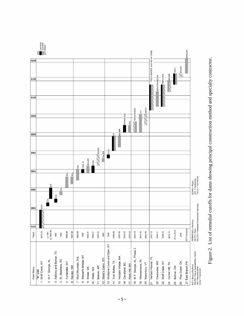
An earlier review by Bruce et al. (2006) detailed 20 North American dams (including one
in Canada) which had been remediated by such diaphragm walls in the period 1975-2005. These
are shown in Figure 2, and represent almost 7,500,000 ft2 of cutoff wall. These walls in dams
were constructed by three methods: clamshell (about 50% total area); hydromill (about 35%);
and secant piles (about 15%). The majority of the projects, and all of the later ones, have used
concrete (conventional or occasionally “plastic”) as the backfill, although one (Addicks and
Barker, TX, 1978-1982) used soil-bentonite, and another (Twin Buttes, TX, 1996-1999) used
soil-cement-bentonite. The deepest clamshell wall (Wells Dam, WA) reached 223 feet, and the
– 5 –
Fig
ure
2. L
ist
of
rem
edia
l cu
toff
s fo
r d
ams
show
ing p
rinci
pal
const
ruct
ion m
ethod a
nd s
pec
ialt
y c
on
trac
tor.
– 6 –
deepest hydromill wall (Mud Mountain, WA) reached over 400 feet. The maximum depth
reached by secant piles is 280 feet (Wolf Creek, KY). These projects have had minimum wall
widths of 1.5 to 3.1 feet, with most being in the range 2 to 3 feet.
Clearly, the intrinsic advantage of Category 1 walls is that the resultant cut-off material
(i.e., the “backfill”) can be engineered to provide an extremely wide range of properties,
independent of the native material through which the cut-off is to be excavated. This ability is so
fundamental that the actual cut-offs are primarily called after the materials themselves, as
opposed to the method of excavation:
conventional concrete walls
plastic concrete walls
cement-bentonite walls (CB)
soil-bentonite walls (SB)
soil-cement-bentonite walls (SCB)
In all cases except CB walls, excavation is conducted under bentonite (or
polymer) slurry which is thereafter displaced out of the trench or panel by the backfill material of
choice. It is generally believed that the concept of excavating under a bentonitic supporting
slurry was first conceived by Veder, in Austria, in 1938, while the first U.S. application was in
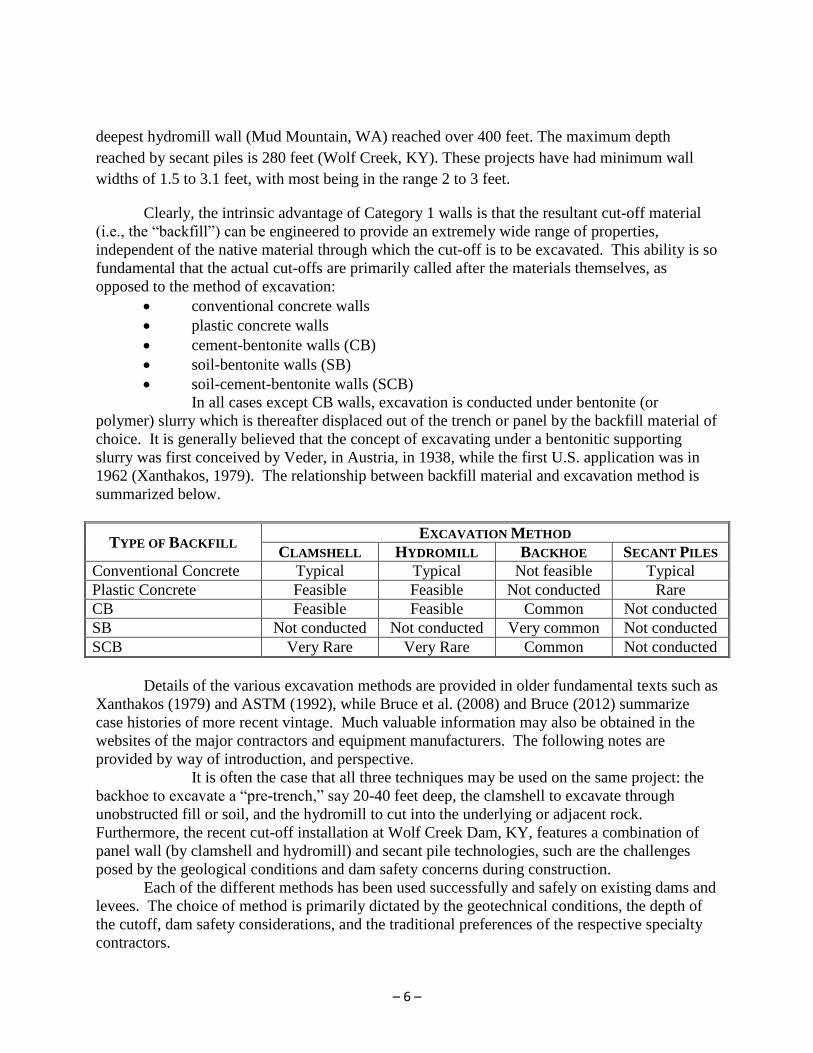
1962 (Xanthakos, 1979). The relationship between backfill material and excavation method is
summarized below.
TYPE OF BACKFILL EXCAVATION METHOD
CLAMSHELL HYDROMILL BACKHOE SECANT PILES
Conventional Concrete Typical Typical Not feasible Typical
Plastic Concrete Feasible Feasible Not conducted Rare
CB Feasible Feasible Common Not conducted
SB Not conducted Not conducted Very common Not conducted
SCB Very Rare Very Rare Common Not conducted
Details of the various excavation methods are provided in older fundamental texts such as
Xanthakos (1979) and ASTM (1992), while Bruce et al. (2008) and Bruce (2012) summarize
case histories of more recent vintage. Much valuable information may also be obtained in the
websites of the major contractors and equipment manufacturers. The following notes are
provided by way of introduction, and perspective.
It is often the case that all three techniques may be used on the same project: the
backhoe to excavate a “pre-trench,” say 20-40 feet deep, the clamshell to excavate through
unobstructed fill or soil, and the hydromill to cut into the underlying or adjacent rock.
Furthermore, the recent cut-off installation at Wolf Creek Dam, KY, features a combination of
panel wall (by clamshell and hydromill) and secant pile technologies, such are the challenges
posed by the geological conditions and dam safety concerns during construction.
Each of the different methods has been used successfully and safely on existing dams and
levees. The choice of method is primarily dictated by the geotechnical conditions, the depth of
the cutoff, dam safety considerations, and the traditional preferences of the respective specialty
contractors.
– 7 –
3. UPDATED LIST OF CASE HISTORIES
Appendix 1 to this paper provides an updated list of Category 1 cutoffs, referred to above in
Figure 2. An enormous amount of work has been conducted for the USACE in the last ten years
or so, to remediate firstly four major DSAC-1 Category Dams (highest risk) and more recently
the most needy of the DSAC-2 Category Dams (slightly lower risk). It may be estimated that the
dollar value of the “new” remediations (i.e., Clearwater, MO, Herbert Hoover, FL, Wolf Creek,
KY, Center Hill, TN, Bolivar, OH, Pine Creek, OK, and East Branch, PA) conducted in the last
ten years is several times that of the combined expenditure (in current dollars) of the preceding
30 years.
4. FINAL REMARKS
It is clear when studying the numerous technical papers on these projects – and having been
involved in one way or another with all of them – that the major technological breakthrough in
recent years was the work conducted at Wolf Creek Dam, KY. This is not to short sell the
innovative construction methods adopted by three different contractors at Herbert Hoover Dike,
FL. However, the standards set in quality control and assurance, in Data Management Systems,
in construction methodologies, and in Dam Safety Management at Wolf Creek truly represented
a “great leap” forward. As one direct consequence, Owners are now being more prescriptive in
their specifications, such is their confidence in the wonderful database of knowledge that has
been forthcoming.
It is highly unlikely that the dam remediation market in the U.S. will ever again see the
sustained levels of activity which characterized the decade from 2007. However, there is
absolutely no doubt that some level of activity will endure, and that, in all likelihood, it will be
characterized by safe and effective solutions in an increasingly competitive commercial
atmosphere.
REFERENCES [in the text and for Case Histories 21-27 in Table 1 only. References for
Case Histories 1-20 may be found in Bruce 2012.]
American Society for Testing and Materials (1992). “Slurry Walls: Design, Construction, and
Quality Control.” ASTM Publication Code Number 04-011290-38. STP 1129. David B.
Paul, Richard R. Davidson and Nicholas J. Cavalli, Editors. September. 425 pp.
Bassola, P., F. Santillan, L. Bedford, M. Zoccola and B. DeBruyn (2013). “State of Art of the
Quality Control at Wolf Creek Dam Remediation Project,” International Conference on
Large Dams, August 12-15, 15 pp.
Bedford, L., F. Santillan, P. Bassola, M. Zoccola and B. DeBruyn (2013). “Wolf Creek Dam
Foundation Remediation - An Innovative Successful Solution,” International Conference
on Large Dams, August 12-15, 19 pp.
Bruce, D.A., A. Ressi di Cervia and J. Amos-Venti. (2006). “Seepage Remediation by Positive
Cut-Off Walls: A Compendium and Analysis of North American Case Histories,”
ASDSO Dam Safety, Boston, MA, September 10-14.

– 8 –
Bruce, D.A., T.L. Dreese, and D.M. Heenan (2008). “Concrete Walls and Grout Curtains in the
Twenty-First Century: The Concept of Composite Cut-Offs for Seepage Control,” USSD
Annual Conference, Portland, OR, April 28-May 2, 35 pp.
Bruce, D.A. (2012). “Specialty Construction Techniques for Dam and Levee Remediation,”
Spon Press an imprint of Taylor and Francis, 304 p.
Bruce, D.A., P.R. Ca`li and M.L. Woodward. (2012). “The History of Deep Mixing in New
Orleans,” Deep Foundations Institute, Fourth International Conference on Grouting and
Deep Mixing, New Orleans, LA, February 15-18.
Bobba, R, H.W. Gault and B.B. Vannoy (2013). “Secant Pile Barrier Wall Overlap, Thickness
and Position at the U.S. Army Corps of Engineers Wolf Creek Dam, Jamestown, KY”
DFI 38th Annual Conference, September 25-28, 10 pp.
Burke, G.K., D.S. Yang, Y. Nishimura, S. Katsukura and U. Weidenmann (2012), “Specialty
Construction Techniques for Dam and Levee Remediation,” Chapter 3, Spon Press, an
imprint of Taylor and Francis, 304 pp.
Greene, B.H., and Sekela, J.E. (2007). "1957 Seepage Case History - East Branch Dam, PA."
Newsletter of the U.S. Society on Dams, Issue No. 143, November 2007.
Greene, B.H., and Sekela, J.E. (2008). "A Case History of a Major Seepage and Internal Erosion
Event at East Branch Dam, Elk County, PA.,"Proceedings of the Conference of the U.S.
Society on Dams, Portland, OR, April-May 2008.
Greene, B.H., Crock, J., Moskovitz, L., and Premozic, J.W. (2010). "Evaluation of Seepage,
Internal Erosion, and Remedial Alternatives for East Branch Dam, Elk County, PA."
Environmental and Engineering Geoscience, Vol. XVI, No. 3, pp. 229-243.
Halpin, E.C. (2010). “Creating a National Levee Safety Program, Recommendations from the
National Committee on Levee Safety,” ASDSO Dam Safety Conference, September 19-
23, Seattle, WA, 22 p.
Martinez, J.D., K.S. Johnson and J.T. Neal. (1998). “Sinkholes in Evaporite Rocks.” American
Scientist, v. 86, no. 1, pp. 38-51.
Mauro, M., C. Morales and J. Taylor. (2012). “Self Hardening Slurry Wall Installation by
Hydromill at the Herbert Hoover Dike - An Innovative Solution,” DFI 37th Annual
Conference on Deep Foundations, October 16-19, 8 pp.
National Inventory of Dams (NID). (2010). http://nid.usace.army.mil.
New Orleans. (2012). Grouting and Deep Mixing, Proceedings of the Fourth International
Conference on Grouting and Deep Mixing, Geotechnical Special Publication No. 228,
Edited by L.F. Johnsen, D.A. Bruce and M.J. Byle, American Society of Civil Engineers,
New Orleans, February 15-18, 2012, 2, 141 p.
Ragon, R. (2011). “National Inventory of Dams Provides Interesting Data and Statistics,” USSD
Newsletter, March, p. 14.
Santillan, F., J. Rosen, R. Bachus and G. Hlepas. (2015). “Collaborative Data Sharing during
Seepage Barrier Wall Construction at Bolivar Dam – Perspectives from Owner,
Contractor and Sub-Contractor,” Deep Foundations Institute, 40th
Annual Conference on
Deep Foundations, October 11-13, Oakland, CA, 10 pp.
Schmutzler, W. and F. Pagliacci (2012). “Digging Deep into the New Orleans Levee Structural
Reinforcement Deep-Soil Mixing Project,” Foundation Drilling Magazine, ADSC: The
International Association of Foundation Drilling, Vol. XXXIII No. 4, May, pp. 18-23.

– 9 –
Schmutzler, W. and F. Leoni (2013). “New Orleans Levee Improvement Project: An OPA
Runner-Up,” Deep Foundations Magazine, The Deep Foundations Institute (DFI),
January/February, pp. 12-15.
Stare, D.P., T.L. Dreese and D.A. Bruce (2012). In “Specialty Construction Techniques for Dam
and Levee Remediation,” Chapter 2, Spon Press an imprint of Taylor and Francis, 304 p.
Weidenmann, U. (2012). In “Specialty Construction Techniques for Dam and Levee
Remediation,” Chapter 3, Spon Press an imprint of Taylor and Francis, 304 p.
Xanthakos, P.P. (1979). “Slurry Walls.” McGraw Hill Book Company, ISBN 0-07-072215-3,
622 p.
– 10 –
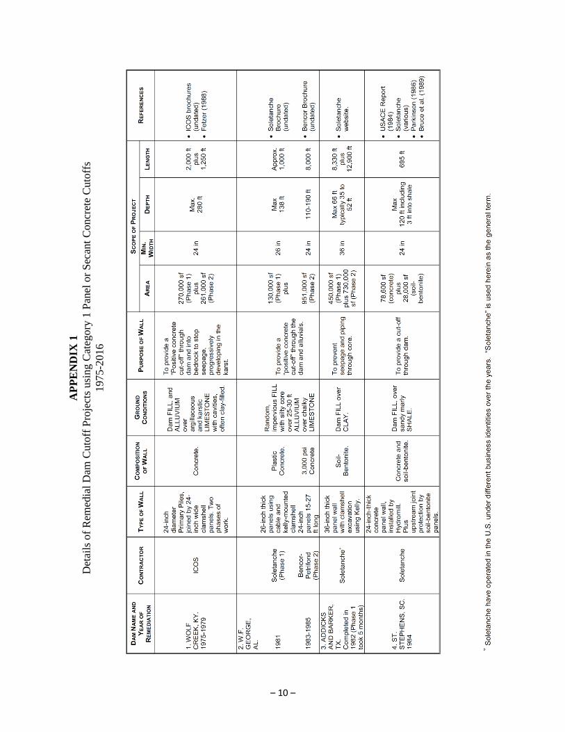
AP
PE
ND
IX 1
Det
ails
of
Rem
edia
l D
am C
uto
ff P
roje
cts
usi
ng
Cat
egory
1 P
anel
or
Sec
ant
Concr
ete
Cuto
ffs
1975-2
016

– 11 –

– 12 –

– 13 –

– 14 –

– 15 –