relio r2 sync server user manual - mesurex.com · sealevel systems, inc. sealevel.com phone...
TRANSCRIPT
Sealevel Systems, Inc. Sealevel.com Phone 864.843.4343
Relio R2 SYNC User Manual
RELIO R2 SYNC

©Sealevel Systems, Inc. R2 SYNC Manual 2 SL9255 7/2015
Contents Introduction .............................................................................................................................................................. 3
Features ..................................................................................................................................................................... 4
COM Express Module/RAM Configuration options ............................................................................................ 4
Before You Get Started ............................................................................................................................................. 5
What’s Included ..................................................................................................................................................... 5
Advisory Conventions ........................................................................................................................................... 5
Optional Items ....................................................................................................................................................... 6
Specifications ............................................................................................................................................................ 8
Mechanical Dimensions ........................................................................................................................................ 8
Environmental Specifications ............................................................................................................................... 8
Operating Temperature Range ............................................................................................................................. 8
Power Supply ......................................................................................................................................................... 9
Power Input .......................................................................................................................................................... 10
Manufacturing ..................................................................................................................................................... 10
System Operation ................................................................................................................................................... 11
Power Button ....................................................................................................................................................... 11
Power States ........................................................................................................................................................ 11
Synchronous Serial Communication Ports ........................................................................................................ 11
Internal Baud Rate Generator ............................................................................................................................. 11
Control and Status Registers Definition ............................................................................................................ 12
Interface Selection ............................................................................................................................................... 14
100-Pin Connector Pin Out ................................................................................................................................. 14
DB-25M Connector Pin Outs ............................................................................................................................... 16
CMOS Battery ....................................................................................................................................................... 21
System Description ................................................................................................................................................. 21
Front Panel I/O Connectors ................................................................................................................................ 21
Rear Panel I/O Connectors ................................................................................................................................. 22
Mechanical Drawings .......................................................................................................................................... 23
Getting Started ........................................................................................................................................................ 28
Where to Get Software ........................................................................................................................................ 28
BIOS Considerations ............................................................................................................................................... 29
Appendix A - Handling Instructions ...................................................................................................................... 30
Appendix B – Electrical Interface ........................................................................................................................... 31
Appendix C – Asynchronous Communications .................................................................................................... 32
Warranty .................................................................................................................................................................. 33

©Sealevel Systems, Inc. R2 SYNC Manual 3 SL9255 7/2015
Introduction The Relio R2 SYNC is an exceptionally rugged embedded controller with integrated synchronous communications ports for operating in harsh environments. The R2 SYNC’s fanless and cableless structure ensures extensive durability for long-term usage. The R2 SYNC differs from traditional industrial computer systems in that it is built using the PICMG COM Express architecture. Sealevel has partnered with the leading COM Express module manufacturers to ensure our customers benefit from the best in the industry. This manual will focus on the higher level features of the R2 SYNC computer system.
The R2 SYNC is compatible with Basic and Compact form factor Type 6 pin out COM Express modules. COM Express is a widely supported implementation of Computer on Module (COM) design. The COM Express architecture reduces the complexity, cost and time required for custom computer system design by combining the processing, memory, video, Ethernet and USB functionality in a small, highly integrated module. COM Express modules install on a carrier board that provides the application specific I/O and external connectors best suited for the system requirements.
Sealevel COM Express carrier boards leverage the company’s years as a leader in I/O and communication products to provide carrier board and full system solutions in the fastest time possible. Common I/O features include serial, analog and digital I/O. Sealevel’s extensive library of proven I/O circuits can be included as required to meet the specific I/O count, voltage ranges, and connector types.
The R2 SYNC is equipped with a four-port RS-232, RS-422, RS-485,EIA-530, EIA-530A, V.35 synchronous serial interface. Designed using the popular Zilog Z85230 Enhanced Serial Communication Controller (ESCC), the board is an ideal solution for military, satellite, radar, banking, and other applications that require robust synchronous communications.
For maximum flexibility, each of the serial ports can be individually configured for RS-232, RS-422, RS-485,EIA-530, EIA-530A, V.35 communications. In RS-232 mode, all common modem control signals are implemented for compatibility with a wide range of peripherals. A digital phase lock loop (DPLL) is included on each port, and the board supports data rates up to 128K bps in burst mode. For easy implementation, a fan-out cable is included that terminates the onboard 100-pin connector to four DB-25M connectors.
Software support, critical for successful synchronous communication development, is provided through Sealevel’s SeaMAC driver. HDLC/SDLC protocols are supported as well as certain configurations of Monosync, Bi-sync, and Raw modes.
The R2 SYNC also utilizes the Exar SP-506 multi-protocol electrical interface chip that allows it to be compliant with EIA/TIA-530/530A, EIA/TIA-232E, EIA/TIA 485, and ITU V.35. Optional cables are available to connect RS-449, RS-530, RS-530A, V.35 and X.21 interfaces.
©Sealevel Systems, Inc. R2 SYNC Manual 4 SL9255 7/2015
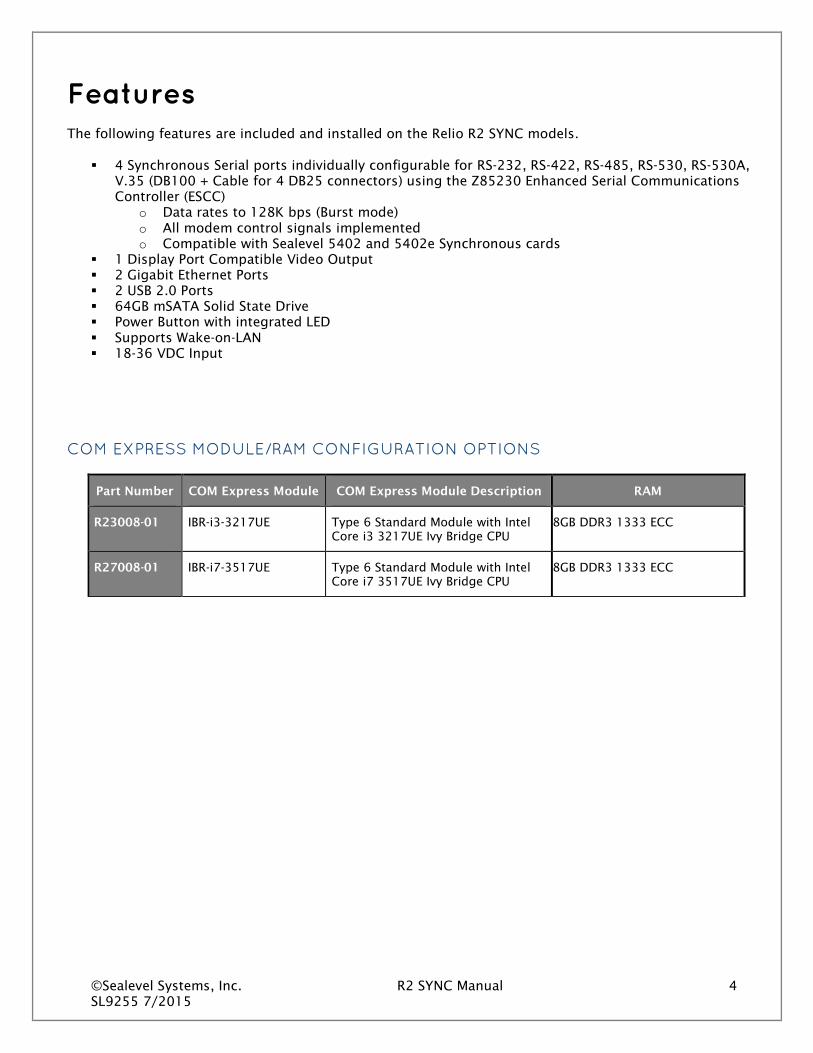
Features The following features are included and installed on the Relio R2 SYNC models.
4 Synchronous Serial ports individually configurable for RS-232, RS-422, RS-485, RS-530, RS-530A, V.35 (DB100 + Cable for 4 DB25 connectors) using the Z85230 Enhanced Serial Communications Controller (ESCC)
o Data rates to 128K bps (Burst mode) o All modem control signals implemented o Compatible with Sealevel 5402 and 5402e Synchronous cards
1 Display Port Compatible Video Output 2 Gigabit Ethernet Ports 2 USB 2.0 Ports 64GB mSATA Solid State Drive Power Button with integrated LED Supports Wake-on-LAN 18-36 VDC Input
COM EXPRESS MODULE/RAM CONFIGURATION OPTIONS
Part Number COM Express Module COM Express Module Description RAM
R23008-01 IBR-i3-3217UE Type 6 Standard Module with Intel Core i3 3217UE Ivy Bridge CPU
8GB DDR3 1333 ECC
R27008-01 IBR-i7-3517UE Type 6 Standard Module with Intel Core i7 3517UE Ivy Bridge CPU
8GB DDR3 1333 ECC

©Sealevel Systems, Inc. R2 SYNC Manual 5 SL9255 7/2015
Before You Get Started WHAT’S INCLUDED
The R2 SYNC is shipped with the following items. If any of these items are missing or damaged, please contact Sealevel at 864.843.4343 for a replacement.
• R2 SYNC Computer System • BK1042 (Wall mount brackets) • CA339 Molex 100-Pin to (4) DB25 Male Cable, 36 inch Length • TR145-US AC/DC Power Supply – Desktop 90-264VAC/47-63Hz 21VDC regulated 3000mA output
with a KPPX-4P connector • Sealevel Software CD with SeaMAC drivers
ADVISORY CONVENTIONS
Warning - The highest level of importance used to stress a condition where damage could result to the product or the user could suffer serious injury.
Important– The middle level of importance used to highlight information that might not seem obvious or a situation that could cause the product to fail.
Note – The lowest level of importance used to provide background information, additional tips, or other non-critical facts that will not affect the use of the product.

©Sealevel Systems, Inc. R2 SYNC Manual 6 SL9255 7/2015
OPTIONAL ITEMS
Depending upon your application, you are likely to find one or more of the following items useful with the R2 SYNC. All items can be purchased from our website (www.sealevel.com) or by calling our sales team at (864) 843-4343.
Cables
CAT5 Patch Cable, 7’ In Length (Part# CA246)
Standard 7' CAT5 Unshielded Twisted Ethernet Pair Patch Cable (RJ45) with blue jacket.
CAT5 Patch Cable, 10' In Length (Part# CA247)
Standard 10’ CAT5 Unshielded Twisted Pair Ethernet Patch Cable (RJ45) with blue jacket.
DB25 Female to DB25 Male Extension Cable, 72 inch Length (Item# CA104)
The CA104 is a standard DB25F to DB25M serial extension cable. Extend a DB25 cable or locate a piece of hardware where it is needed with this six foot (72 inch) cable. The connectors are pinned one-to-one so the cable is compatible with any device or cable with DB25 connectors. The cable is fully shielded against interference and the connectors are molded to provide strain relief. Dual metal thumbscrews secure the cable connections and prevent accidental disconnection. Recommended for applications with data rates less than 1M bps.
DB25 Female (RS-530) to DB37 Male (RS-449 DTE) Cable, 10 inch Length (Item# CA107)
DB25 Female (RS-530) to DB37 Male (RS-449 DTE) Cable, 10 inch Length. RS-530 was designed to replace the bulky DB37 RS-449 connector. The CA107 cable allows any Sealevel RS-530 adapter to be used in an RS-449 application.
DB25 Female (RS-530) to DB15 Male (X.21) Cable, 72 inch Length (Item# CA159)

©Sealevel Systems, Inc. R2 SYNC Manual 7 SL9255 7/2015
DB25 Female (RS-530) to DB15 Male (X.21) Cable, 72 inch Length. Converts the Standard DB25 implementation of RS-530 or RS-422 to the ITU-T X.21 standard pinout.
DB25 Female to DB25 Male (RS-530) Twisted Pair Serial Cable, 72 inch Length (Item# CA174)
DB25 Female to DB25 Male Twisted Pair Serial Cable, 72 inch Length. Twisted Pairs provide increased data integrity in high-speed serial applications. Recommended for RS-530 applications with data rates greater than 1M bps.
DB25 Female (V.35) to ITU-T ISO-2593 Style Connector (V.35) Cable, 72 inch Length (Item# CA178)
DB25 Female (V.35) to ITU-T ISO-2593 Style Connector (V.35) Cable, 72 inch Length. The CA178 converts the Sealevel DB25 implementation of V.35 to the ITU-T V.35 mechanical standard.

©Sealevel Systems, Inc. R2 SYNC Manual 8 SL9255 7/2015
Specifications MECHANICAL DIMENSIONS
Length 7.820 inches (19.86 cm)
Width1 4.744 inches (12.04 cm)
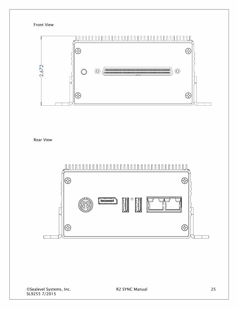
Height 2.672 inches (6.90 cm)
ENVIRONMENTAL SPECIFICATIONS
Specification Operating Storage
Temperature Range 0 to 50 ºC (32 to 185 ºF)
2 -40 to 85 ºC (-40 to 221 ºF)
Humidity Range 10 to 90% R.H. Non-Condensing 10 to 90% R.H. Non-Condensing
OPERATING TEMPERATURE RANGE
Part Number COM Express Module Operating Temperature
Range Comment
R23008-01 IBR-i3-3217UE 0 - 50 °C Requires Industrial Temperature SSD
R27008-01 IBR-i7-3517UE 0 - 50 °C Requires Industrial Temperature SSD
The R2 SYNC7008 can operate with no airflow at 50C as long as the steady-state CPU usage does not exceed 50%. If CPU usage is sustained at a workload greater than 50%, the CPU will throttle itself back to keep its internal temperature in a safe range.
If the application environment requires the computer to operate at 50C with steady state CPU usage greater than 50%, some additional cooling must be used to ensure safe operation of the electronics.
The R2 SYNC computer system is a fan-less, solid state computer that relies on thermal conduction to move heat from internal components to the outside of the enclosure. The lid is designed as a finned heat sink to increase overall surface area. Three main cooling methods can be used to optimize removal of heat from the system.
1 Width listed is for computer without mounting brackets. Total width with brackets is shown in drawings. 2 Operating temperature is dependent on particular model. See the Operating Temperature Range section for model capabilities.

©Sealevel Systems, Inc. R2 SYNC Manual 9 SL9255 7/2015
1. Airflow 2. Thermal conduction through mounting 3. Computer orientation
Airflow over the lid provides the most effective heat removal of these three options. It is optimal to mount the computer in an area that has either natural or forced airflow to constantly remove heat from the enclosure.
Mounting the computer to a large thermally conductive surface (such as an I-Beam, steel cabinet or other large metal surface) allows heat to travel through the enclosure and be dissipated into the large structure.
POWER SUPPLY
The power supply provided has a universal AC input. It provides 21 VDC @ 3.0 A max output to the R2 SYNC system. Typical power consumption varies depending on COM Express Module, memory capacity, OS/software activity and peripheral devices. AC current draw will never exceed 1.4 A.
All necessary system voltages are generated from a single DC input capable of accepting 18 VDC to 36 VDC (fed by above DC power supply).
Acceptable System Input Voltage 18 VDC-36 VDC
DC Current Rating (Dependent on COM Express Module , input voltage and load)
375 mA-2150 mA
©Sealevel Systems, Inc. R2 SYNC Manual 10 SL9255 7/2015
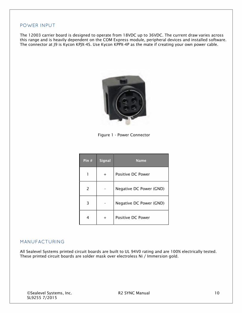
POWER INPUT
The 12003 carrier board is designed to operate from 18VDC up to 36VDC. The current draw varies across this range and is heavily dependent on the COM Express module, peripheral devices and installed software. The connector at J9 is Kycon KPJX-4S. Use Kycon KPPX-4P as the mate if creating your own power cable.
Figure 1 - Power Connector
Pin # Signal Name
1 + Positive DC Power
2 - Negative DC Power (GND)
3 - Negative DC Power (GND)
4 + Positive DC Power
MANUFACTURING
All Sealevel Systems printed circuit boards are built to UL 94V0 rating and are 100% electrically tested. These printed circuit boards are solder mask over electroless Ni / Immersion gold.

©Sealevel Systems, Inc. R2 SYNC Manual 11 SL9255 7/2015
System Operation POWER BUTTON
The power button on the front of the computer can be used to turn the system on, shut the system down or place the computer in sleep states S3 or S4 (depending on OS support and configuration). The power button can also wake the system up from sleep states S3 or S4.
The power button has a 3 second hardware debounce/delay built in so accidental shutdown does not occur. This 3 second delay is present at all times so the power button must be held for 3 seconds before system power up, power down, sleep or wake occurs.
POWER STATES
The R2 SYNC is designed to operate in four Power States as defined by ACPI.
S0 – Fully powered and operational
S3 – Suspended to memory (known as sleep in Windows)
S4 – Suspended to disk (known as Hibernate in Windows)
S5 – Powered down in standby (Windows Shutdown)
The system can transition from S0 to any of the three listed standby states (S3, S4, or S5) by either software command or the Power Button. The system can then be awoken from either listed sleep/standby state by holding the Power Button for 3 seconds. The system can also be awoken from S3 or S4 with a USB input device such as a HID compliant keyboard or mouse.
To be awoken from a standby state with a USB device, the device must be present when the computer enters the sleep state and must remain connected for the duration of the sleep state.
These power states are supported by Windows 8, Windows 7, Windows Vista, and Windows XP.
SYNCHRONOUS SERIAL COMMUNICATION PORTS
The R2 SYNC utilizes the Zilog Z85230 Enhanced Serial Communications Controller (ESCC) and includes a dedicated Z85230 per port. This chip features programmable baud rate, data format and interrupt control. Refer to the ESCC User Manual, available from Zilog, for details on programming the 85230 ESCC chip in the event you are writing your own driver as opposed to using the SeaMAC driver.
INTERNAL BAUD RATE GENERATOR
The baud rate of the ESCC is programmed under software control. The standard oscillator supplied with the board is 7.3728 MHz. However, other oscillator values can be substituted to achieve different baud rates. It should be noted that the Z85230 chip is manufactured in different speed ranges and installation of a different oscillator may also require changing the Z85230.

©Sealevel Systems, Inc. R2 SYNC Manual 12 SL9255 7/2015
CONTROL AND STATUS REGISTERS DEFINITION
The control and status registers occupy 16 consecutive I/O locations. The following tables provide a functional description of the bit positions. This table is provided for users that desire to write their own driver.
X = do not care.
Base
Mode
D7 D6 D5 D4 D3 D2 D1 D0
+4 RD 0 IRQST 0 0 0 0 0 DSRA
+5 RD 485CLK ECHOA SYNCA_RTS SYNCA_CTS AM3 AM2 AM1 AM0
+5 WR 485CLK ECHOA SYNCA_RTS SYNCA_CTS AM3 AM2 AM1 AM0
+6 RD 0 0 0 0 RLA LLA TSETSLA RXCOPTA
+6 WR X X X X RLA LLA TSETSLA RXCOPTA
+7 RD X X X X IRQST4 IRQST3 IRQST2 IRQST1
+14 RD SD7 SD6 SD5 SD4 SD3 SD2 SD1 SD0
+15 RD SD15 SD14 SD13 SD12 SD11 SD10 SD9 SD8

©Sealevel Systems, Inc. R2 SYNC Manual 13 SL9255 7/2015
Field Description
IRQST SCC interrupt status: 1 = No interrupt pending on ESCC 0 = Interrupt pending on ESCC.
DSRA DSRA: 1 = DSRA not active 0 = DSRA active
LLA Local Loopback: 1 = LL set 0 = LL not set
RLA Remote Loopback: 1 = RL set 0 = RL not set
TSETSLA TSET clock source: 1= Received TXC as source 0 = TRXCA as source
RXCOPTA RXCOPTA: 1= Selects SCC PCLK for RTXCA 0 = Selects received RXC for
RTXCA
SYNCA_RTS SYNCA _RTS: 1 = SYNCA connected to RTS 0 = SYNCA is high
SYNCA_CTS SYNCA_CTS: 1 = SYNCA connected to CTS 0 = SYNCA is high
485CLK TSET switches with TXD:
1 = clk switches 0 = no CLK switching
ECHOA ECHO enable: 1 = echo disabled 0 = echo enabled
AM0 – AM3 I/O mode select. See table for valid interface options. 0 = High Impedance
SD0 – SD15 Optional security feature. Unique value per customer or application.
Default value = FFFF

©Sealevel Systems, Inc. R2 SYNC Manual 14 SL9255 7/2015
INTERFACE SELECTION
The R2 SYNC supports a variety of electrical interfaces. Refer to the Control and Status Register Definitions found in the Technical Description section of this manual for this bit description. There is line termination on RXD, RXC and TXC in the following modes: RS-530, RS-530A, RS-485T and V.35. This table is provided for users that desire to write their own driver. By default, at power-up, all signals are high impedance.
HEX M3 M2 M1 M0 Interface Mode
0 0 0 0 0 All signals are high impedance
1 0 0 0 1 * not supported *
2 0 0 1 0 RS-232
3 0 0 1 1 * not supported *
4 0 1 0 0 RS-485T with 120Ω termination
5 0 1 0 1 RS-485 without termination
6,7,8,9 0 1 1 0 * not supported *
A 1 0 1 0 single ended loopback
B 1 0 1 1 differential loopback
C 1 1 0 0 * not supported *
D 1 1 0 1 RS-530
E 1 1 1 0 V.35
F 1 1 1 1 RS-530A
100-PIN CONNECTOR PIN OUT
The R2 SYNC has a 100-pin high-density connector and includes a cable (Item# CA339) that breaks out to four (4) DB25 male connectors. The pin outs for RS-232, RS-485, RS-530, RS-530A and V.35 interfaces on the DB25 connectors are listed on the following pages. For customers designing their own cable, the mating 100-pin connector is AMP Part# 5787169-9. The pin out for the 100-pin connector is listed below.

©Sealevel Systems, Inc. R2 SYNC Manual 15 SL9255 7/2015
100-Pin Connector
Signal Name DB25 Port 1 Port 2 Port 3 Port 4
N/C 1 51 26 76
GND 7 2 52 27 77
TXD- 2 3 53 28 78
TXD+ 14 4 54 29 79
RTS- 4 5 55 30 80
RTS+ 19 6 56 31 81
DTR- 20 7 57 32 82
DTR+ 23 8 58 33 83
TSET- 24 9 59 34 84
TSET+ 11 10 60 35 85
RXD- 3 11 61 36 86
RXD+ 16 12 62 37 87
CTS- 5 13 63 38 88
CTS+ 13 14 64 39 89
DSR- 6 15 65 40 90
DSR+ 22 16 66 41 91
DCD- 8 17 67 42 92
DCD+ 10 18 68 43 93
TXC- 15 19 69 44 94
TXC+ 12 20 70 45 95
RXC- 17 21 71 46 96
RXC+ 9 22 72 47 97
LL- 18 23 73 48 98
RL- 21 24 74 49 99
NC 25 75 50 100
SHIELD Shell Shell Shell Shell Shell

©Sealevel Systems, Inc. R2 SYNC Manual 16 SL9255 7/2015
DB-25M CONNECTOR PIN OUTS
RS-232 SIGNALS
Base+5, M3-M0=2, 0010
Pin # Signal Name Mode
2 TD Transmit Data Output
3 RD Receive Data Input
4 RTS Request To Send Output
5 CTS Clear To Send Input
6 DSR Data Set Ready Input
7 GND Ground
8 DCD Data Carrier Detect Input
15 TXC Transmit Clock Input
17 RXC Receive Clock Input
18 LL Local Loopback Output
20 DTR Data Terminal Ready Output
21 RL Remote Loopback Output
24 TSET Transmit Signal Element Timing Output

©Sealevel Systems, Inc. R2 SYNC Manual 17 SL9255 7/2015
RS-485 OR RS-485T
Base+5, M3-M0=4, 0100 (With termination) Base+5, M3-M0=5, 0101 (Without termination)
Pin # Signal Name Mode
2 TDA TX– Transmit Negative Output
3 RDA RX– Receive Negative Input
7 GND Ground
9 RXCB RXC+ Receive Clock Positive Input
11 TSETB TSET+ Transmit Signal Element Timing + Output
12 TXCB TXC+ Transmit Clock Positive Input
14 TDB TX+ Transmit Positive Output
15 TXCA TXC– Transmit Clock Negative Input
16 RDB RX+ Receive Positive Input
17 RXCA RXC– Receive Clock Negative Input
24 TSETA TSET– Transmit Signal Element Timing – Output

©Sealevel Systems, Inc. R2 SYNC Manual 18 SL9255 7/2015
RS-530 (RS-422)
Base+5, M3-M0=D, 1101
Pin # Signal Name Mode
2 TDA TX– Transmit Negative Output
3 RDA RX– Receive Negative Input
4 RTSA RTS– Request To Send Negative Output
5 CTSA CTS– Clear To Send Negative Input
6 DSRA DSR– Data Set Ready Negative Input
7 GND Ground
8 DCDA DCD– Data Carrier Detect Negative Input
9 RXCB RXC+ Receive Clock Positive Input
10 DCDB DCD+ Data Carrier Detect Positive Input
11 TSETB TSET+ Transmit Signal Element Timing + Output
12 TXCB TXC+ Transmit Clock Positive Input
13 CTSB CTS+ Clear To Send Positive Input
14 TDB TX+ Transmit Positive Output
15 TXCA TXC– Transmit Clock Negative Input
16 RDB RX+ Receive Positive Input
17 RXCA RXC– Receive Clock Negative Input
18 LL Local Loopback Output
19 RTSB RTS+ Request To Send Positive Output
20 DTRA DTR– Data Terminal Ready Negative Output
21 RL Remote Loopback Output
22 DSRB DSR+ Data Set Ready Positive Input
23 DTRB DTR+ Data Terminal Ready Positive Output
24 TSETA TSET– Transmit Signal Element Timing – Output
©Sealevel Systems, Inc. R2 SYNC Manual 19 SL9255 7/2015
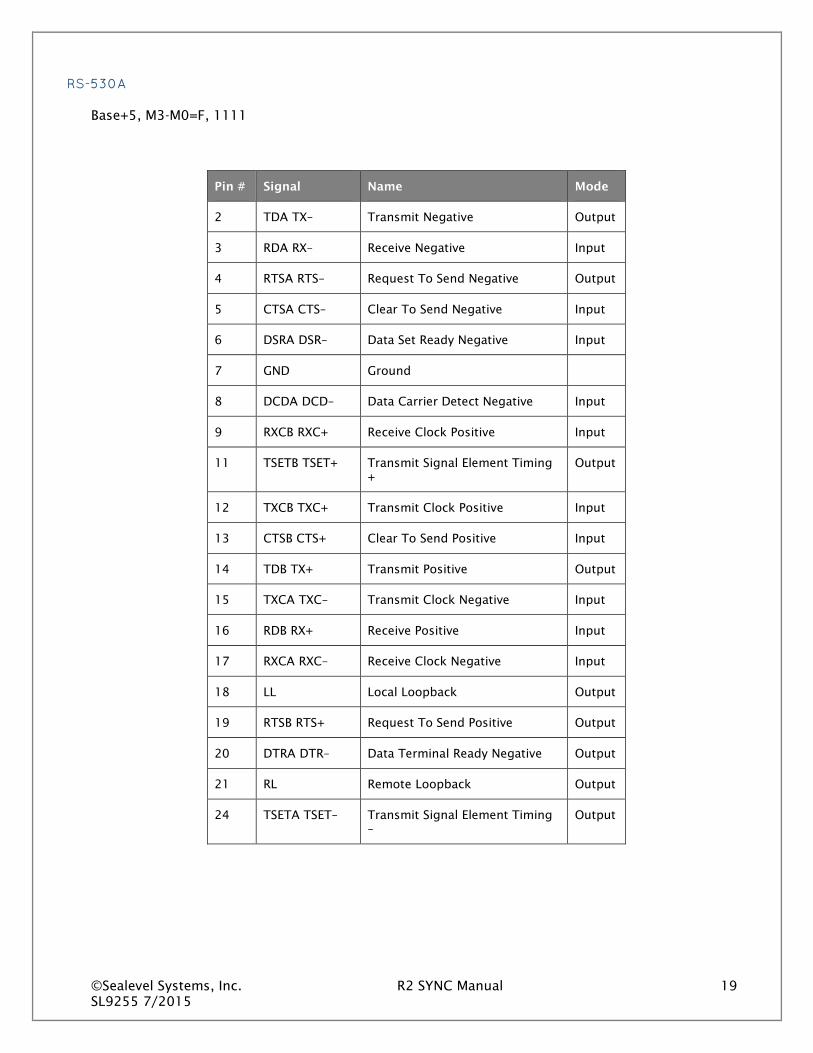
RS-530A
Base+5, M3-M0=F, 1111
Pin # Signal Name Mode
2 TDA TX– Transmit Negative Output
3 RDA RX– Receive Negative Input
4 RTSA RTS– Request To Send Negative Output
5 CTSA CTS– Clear To Send Negative Input
6 DSRA DSR– Data Set Ready Negative Input
7 GND Ground
8 DCDA DCD– Data Carrier Detect Negative Input
9 RXCB RXC+ Receive Clock Positive Input
11 TSETB TSET+ Transmit Signal Element Timing +
Output
12 TXCB TXC+ Transmit Clock Positive Input
13 CTSB CTS+ Clear To Send Positive Input
14 TDB TX+ Transmit Positive Output
15 TXCA TXC– Transmit Clock Negative Input
16 RDB RX+ Receive Positive Input
17 RXCA RXC– Receive Clock Negative Input
18 LL Local Loopback Output
19 RTSB RTS+ Request To Send Positive Output
20 DTRA DTR– Data Terminal Ready Negative Output
21 RL Remote Loopback Output
24 TSETA TSET– Transmit Signal Element Timing –
Output

©Sealevel Systems, Inc. R2 SYNC Manual 20 SL9255 7/2015
V.35 SIGNALS
Base+5, M3-M0=E, 1110
Pin # Signal Name V.35 Mode
2 TDA TX– Transmit Negative P Output
3 RDA RX– Receive Negative R Input
4 RTS Request To Send C Output *
5 CTS Clear To Send D Input *
6 DSR Data Set Ready E Input *
7 GND Ground B
8 DCD Data Carrier Detect F Input *
9 RXCB RXC+ Receive Clock Positive X Input
11 TSETB TSET+ Transmit Signal Element Timing + W Output
12 TXCB TXC+ Transmit Clock Positive AA Input
14 TDB TX+ Transmit Positive S Output
15 TXCA TXC– Transmit Clock Negative Y Input
16 RDB RX+ Receive Positive T Input
17 RXCA RXC– Receive Clock Negative V Input
18 LL Local Loopback Output *
20 DTR Data Terminal Ready H Output *
21 RL Remote Loopback Output *
24 TSETA TSET– Transmit Signal Element Timing – U Output
All modem control signals are single ended (un-balanced) with RS-232 signal levels.

©Sealevel Systems, Inc. R2 SYNC Manual 21 SL9255 7/2015
CMOS BATTERY
The R2 SYNC includes a 3V DC type CR2032 battery that supplies the RTC and CMOS memory of the COM Express CPU module.
Danger of explosion if battery is incorrectly replaced – Replace only with the same or equivalent type recommended by the manufacturer. Dispose of used batteries according to the manufacturer’s instructions.
To fulfill the requirements of EN 60950, the R2 SYNC incorporates two current-limiting devices (resistor and diode) in the battery power supply path.
System Description The following I/O connectors use industry standard pin outs for maximum compatibility.
FRONT PANEL I/O CONNECTORS

©Sealevel Systems, Inc. R2 SYNC Manual 22 SL9255 7/2015
REAR PANEL I/O CONNECTORS

©Sealevel Systems, Inc. R2 SYNC Manual 23 SL9255 7/2015
MECHANICAL DRAWINGS
Top View
©Sealevel Systems, Inc. R2 SYNC Manual 24 SL9255 7/2015
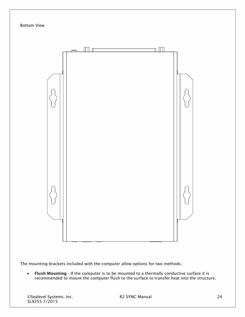
Bottom View
The mounting brackets included with the computer allow options for two methods.
• Flush Mounting - If the computer is to be mounted to a thermally conductive surface it is recommended to mount the computer flush to the surface to transfer heat into the structure.
©Sealevel Systems, Inc. R2 SYNC Manual 25 SL9255 7/2015
Front View
Rear View

©Sealevel Systems, Inc. R2 SYNC Manual 26 SL9255 7/2015
Side View
• Raised Mounting - If the computer is to be mounted to a thermally insulating surface (such as a
plastic or wood surface); it is recommended to use the method that raises the computer 0.5” off the surface. This will allow additional airflow to remove heat from the bottom of the enclosure. Front view (raised)
©Sealevel Systems, Inc. R2 SYNC Manual 27 SL9255 7/2015
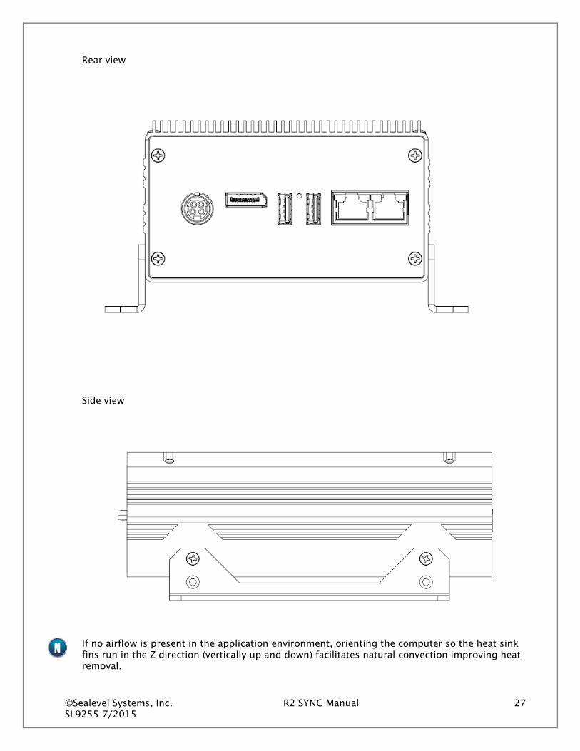
Rear view
Side view
If no airflow is present in the application environment, orienting the computer so the heat sink fins run in the Z direction (vertically up and down) facilitates natural convection improving heat removal.

©Sealevel Systems, Inc. R2 SYNC Manual 28 SL9255 7/2015
Getting Started The Base R2 SYNC computer system includes a 64GB solid state drive. The OS and all necessary software drivers will be preinstalled.
If you wish to install the operating system yourself, you will need to install the applicable drivers. Some drivers apply to the hardware on the COM Express module; some are for devices present on the carrier board. The following table lists the devices that will require drivers.
Device Location Driver Source
Chipset COM Express Module COM Express Module Manufacturer
Integrated Graphics COM Express Module COM Express Module Manufacturer
Network Connection 1 COM Express Module COM Express Module Manufacturer
Network Connection 2 Carrier Board Intel website
WHERE TO GET SOFTWARE
All Sealevel products are shipped with media containing the installers for each software package available. If the media is otherwise unavailable or if desired, the current versions of Sealevel software packages can be obtained from the Sealevel website (see following instructions). If you already have the Sealevel software, proceed to the Windows or Linux installation section.
The following table provides the COM Express module manufacturers for the different models of R2 SYNC computers.
Model Manufacturer Vendor Website Module Family
R23008-01 ADlink www.adlinktech.com Express-IBR R27008-01 ADlink www.adlinktech.com Express-IBR
The network adapter on the carrier board is implemented with an Intel 82574IT NIC on a PCIe x1 lane and provides (1) 10/100/1000Mbps 802.3 compliant Ethernet connection. Install Intel’s “Network Adapter Driver for Windows 7” driver (version 18.4). This can be found at https://downloadcenter.intel.com/
Sealevel software drivers for this computer system can be found at the following link: http://www.sealevel.com/support/article/AA-00584.
The R2 SYNC is compatible with the Sealevel 5402e Synchronous card and uses the same SeaMAC software driver (installed).
©Sealevel Systems, Inc. R2 SYNC Manual 29 SL9255 7/2015
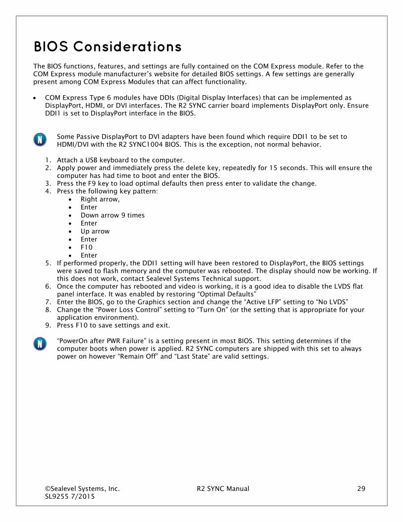
BIOS Considerations The BIOS functions, features, and settings are fully contained on the COM Express module. Refer to the COM Express module manufacturer’s website for detailed BIOS settings. A few settings are generally present among COM Express Modules that can affect functionality.
• COM Express Type 6 modules have DDIs (Digital Display Interfaces) that can be implemented as DisplayPort, HDMI, or DVI interfaces. The R2 SYNC carrier board implements DisplayPort only. Ensure DDI1 is set to DisplayPort interface in the BIOS.
Some Passive DisplayPort to DVI adapters have been found which require DDI1 to be set to HDMI/DVI with the R2 SYNC1004 BIOS. This is the exception, not normal behavior.
1. Attach a USB keyboard to the computer. 2. Apply power and immediately press the delete key, repeatedly for 15 seconds. This will ensure the
computer has had time to boot and enter the BIOS. 3. Press the F9 key to load optimal defaults then press enter to validate the change. 4. Press the following key pattern:
• Right arrow, • Enter • Down arrow 9 times • Enter • Up arrow • Enter • F10 • Enter
5. If performed properly, the DDI1 setting will have been restored to DisplayPort, the BIOS settings were saved to flash memory and the computer was rebooted. The display should now be working. If this does not work, contact Sealevel Systems Technical support.
6. Once the computer has rebooted and video is working, it is a good idea to disable the LVDS flat panel interface. It was enabled by restoring “Optimal Defaults”
7. Enter the BIOS, go to the Graphics section and change the “Active LFP” setting to “No LVDS” 8. Change the “Power Loss Control” setting to “Turn On” (or the setting that is appropriate for your
application environment). 9. Press F10 to save settings and exit.
“PowerOn after PWR Failure” is a setting present in most BIOS. This setting determines if the computer boots when power is applied. R2 SYNC computers are shipped with this set to always power on however “Remain Off” and “Last State” are valid settings.
©Sealevel Systems, Inc. R2 SYNC Manual 30 SL9255 7/2015
Appendix A - Handling Instructions ESD Warnings
Electrostatic Discharges (ESD)
• A sudden electrostatic discharge can destroy sensitive components. Proper packaging and
grounding rules must therefore be observed. Always take the following precautions:
Transport boards and cards in electrostatically secure containers or bags.
• Keep electrostatically sensitive components in their containers, until they arrive at an
electrostatically protected workplace.
• Only touch electrostatically sensitive components when you are properly grounded.
• Store electrostatically sensitive components in protective packaging or on anti-static mats.
Grounding Methods
The following measures help to avoid electrostatic damages to the device:
• Cover workstations with approved antistatic material. Always wear a wrist strap connected to a
properly grounded workplace.
• Use antistatic mats, heel straps, and/or air ionizers for more protection.
• Always handle electrostatically sensitive components by their edge or by their casing.
• Avoid contact with pins, leads, or circuitry.
• Turn off power and input signals before inserting and removing connectors or connecting test
equipment.
• Keep work area free of non-conductive materials such as ordinary plastic assembly aids and
Styrofoam.
• Use field service tools such as cutters, screwdrivers, and vacuum cleaners that are conductive.

©Sealevel Systems, Inc. R2 SYNC Manual 31 SL9255 7/2015
Appendix B --- Electrical Interface RS-232
Quite possibly the most widely used communication standard is RS-232. This implementation has been defined and revised several times and is often referred to as RS-232 or EIA/TIA-232. The IBM PC computer defined the RS-232 port on a 9-pin D-sub connector, and subsequently, the EIA/TIA approved this implementation as the EIA/TIA-574 standard. This standard is defined as the 9-Position Non-Synchronous Interface between Data Terminal Equipment and Data Circuit-Terminating Equipment Employing Serial Binary Data Interchange. Both implementations are in widespread use and will be referred to as RS-232 in this document. RS-232 is capable of operating at data rates up to 20K bps at distances less than 50 ft. The absolute maximum data rate may vary due to line conditions and cable lengths. RS-232 is a single-ended or unbalanced interface, meaning that a single electrical signal is compared to a common signal (ground) to determine binary logic states. The RS-232 and the EIA/TIA-574 specification define two types of interface circuits: Data Terminal Equipment (DTE) and Data Circuit-Terminating Equipment (DCE).
RS-485
RS-485 is backwardly compatible with RS-422; however, it is optimized for partyline or multi-drop applications. The output of the RS-485 driver is capable of being Active (enabled) or Tri-State (disabled). This capability allows multiple ports to be connected in a multi-drop bus and selectively polled. RS-485 allows cable lengths up to 4000 feet and data rates up to 10 Megabits per second. The signal levels for RS-485 are the same as those defined by RS-422. RS-485 has electrical characteristics that allow for 32 drivers and 32 receivers to be connected to one line. This interface is ideal for multi-drop or network environments. RS-485 tri-state driver (not dual-state) will allow the electrical presence of the driver to be removed from the line. Only one driver may be active at a time and the other driver(s) must be tri-stated. RS-485 can be cabled in two ways, two wire and four wire mode. Two wire mode does not allow for full duplex communication, and requires that data be transferred in only one direction at a time. For half-duplex operation, the two transmit pins should be connected to the two receive pins (Tx+ to Rx+ and Tx- to Rx-). Four wire mode allows full duplex data transfers. RS-485 does not define a connector pin-out or a set of modem control signals. RS-485 does not define a physical connector.

©Sealevel Systems, Inc. R2 SYNC Manual 32 SL9255 7/2015
Appendix C --- Asynchronous Communications Serial data communications implies that individual bits of a character are transmitted consecutively to a receiver that assembles the bits back into a character. Data rate, error checking, handshaking, and character framing (start/stop bits) are pre-defined and must correspond at both the transmitting and receiving ends.
Asynchronous communications are the standard means of serial data communication for PC compatible and PS/2 computers. The original PC was equipped with a communication or COM port that was designed around an 8250 Universal Asynchronous Receiver Transmitter (UART). This device allows asynchronous serial data to be transferred through a simple and straightforward programming interface. A starting bit followed by a pre-defined number of data bits (5, 6, 7, or 8) defines character boundaries for asynchronous communications. The end of the character is defined by the transmission of a pre-defined number of stop bits (usually 1, 1.5, or 2). An extra bit used for error detection is often appended before the stop bits. The diagram below demonstrates asynchronous communication bits.
This special bit is called the parity bit. Parity is a simple method of determining if a data bit has been lost or corrupted during transmission. There are several methods for implementing a parity check to guard against data corruption. Common methods are called (E)ven Parity or (O)dd Parity. Sometimes parity is not used to detect errors on the data stream. This is referred to as (N)o parity. Because each bit in asynchronous communications is sent consecutively, it is easy to generalize asynchronous communications by stating that each character is wrapped (framed) by pre-defined bits to mark the beginning and end of the serial transmission of the character. The data rate and communication parameters for asynchronous communications have to be the same at both the transmitting and receiving ends. The communication parameters are baud rate, parity, number of data bits per character, and stop bits (i.e., 9600,N,8,1).
©Sealevel Systems, Inc. R2 SYNC Manual 33 SL9255 7/2015
Warranty Sealevel's commitment to providing the best I/O solutions is reflected in the Lifetime Warranty that is standard on all Sealevel manufactured I/O products. Relio™ industrial computers are warranted for a period of two years and the R9 family is warranted for a five year period from date of purchase. We are able to offer this warranty due to our control of manufacturing quality and the historically high reliability of our products in the field. Sealevel products are designed and manufactured at its Liberty, South Carolina facility, allowing direct control over product development, production, burn-in and testing. Sealevel achieved ISO-9001:2008 certification in 2011.
Warranty Policy
Sealevel Systems, Inc. (hereafter "Sealevel") warrants that the Product shall conform to and perform in accordance with published technical specifications and shall be free of defects in materials and workmanship for the warranty period. In the event of failure, Sealevel will repair or replace the product at Sealevel's sole discretion. Failures resulting from misapplication or misuse of the Product, failure to adhere to any specifications or instructions, or failure resulting from neglect, abuse, accidents, or acts of nature are not covered under this warranty.
Warranty service may be obtained by delivering the Product to Sealevel and providing proof of purchase. Customer agrees to insure the Product or assume the risk of loss or damage in transit, to prepay shipping charges to Sealevel, and to use the original shipping container or equivalent. Warranty is valid only for original purchaser and is not transferable.
This warranty applies to Sealevel manufactured Product. Product purchased through Sealevel but manufactured by a third party will retain the original manufacturer's warranty.
Non-Warranty Repair/Retest
Products returned due to damage or misuse and Products retested with no problem found are subject to repair/retest charges. A purchase order or credit card number and authorization must be provided in order to obtain an RMA (Return Merchandise Authorization) number prior to returning Product.
How to obtain an RMA (Return Merchandise Authorization)
If you need to return a product for warranty or non-warranty repair, you must first obtain an RMA number. Please contact Sealevel Systems, Inc. Technical Support for assistance:
Available Monday – Friday, 8:00AM to 5:00PM EST Phone 864-843-4343 Email [email protected]
Trademarks
Sealevel Systems, Incorporated acknowledges that all trademarks referenced in this manual are the service mark, trademark, or registered trademark of the respective company.