reliance worldwide corporation (uk) ltd thermomix ... · thermomix ufhl the manifold control pack...
TRANSCRIPT

THERMO
MIX
UFHL
The Manifold Control Pack provides temperature controlled mixed water to an underfloor heating system
with a heat output up to 14kW.
Installation and Maintenance Instructions
Thermomix® Underfloor Heating Control Pack
Reliance Worldwide Corporation (UK) LtdWorcester Road,
Evesham,Worcester, WR11 4RA,
UK
Tel: +44 (0)1386 712 400 Fax: +44 (0)1895 712 401
www.rwc.co.uk
Reliance Worldwide Corporation (UK) Ltd reserves the right to make changes to the product which may affect the accuracy of information contained in this leaflet.
ZINS970370_002_09-17
6
Reliance Worldwide Corporation (UK) Ltd
Reliance Worldwide Corporation (UK) Ltd are part of the Australian based group of companies collectively known as Reliance Worldwide Corporation, with the UK brand known as Reliance Water Controls.
Reliance Worldwide Corporation (UK) Ltd is a specialist in the design, distribution and technical support for temperature and flow controls.
With group offices and manufacturing plants throughout the world RWC offers a wealth of knowledge and expertise which is reflected throughout our products. Being part of many specialised trade associations and having our own UKAS accredited laboratory, makes us at the forefront of any new regulations or changes which impact the industry, and allows for continous product development and innovation, within our specialised product area.
Our core product range is related to thermostatic control, with the manufacturing undertaken at our head office in Brisbane Australia, we have an extensive range of thermostatic mixing valves, shower control valves, and taps all which use the same high quality technology to control the temperature of water, within this range we have different valves to suit various applications and working parameters, including both TMV2 and TMV3 approved controls.
RWC, are market leaders of OEM controls with a complete range of safety valves for use in G3 unvented systems and a wide range of Underfloor heating controls (UFH) to allow for safe distribution of hot water, throughout a property. This range includes; thermostatic control valves for safe hot water temperatures, manifolds to enable even distribution, complete UFH kits to allow ease of installation & commisioning, and a range of modern and stylish programmers to complement these controls.
Notes
1
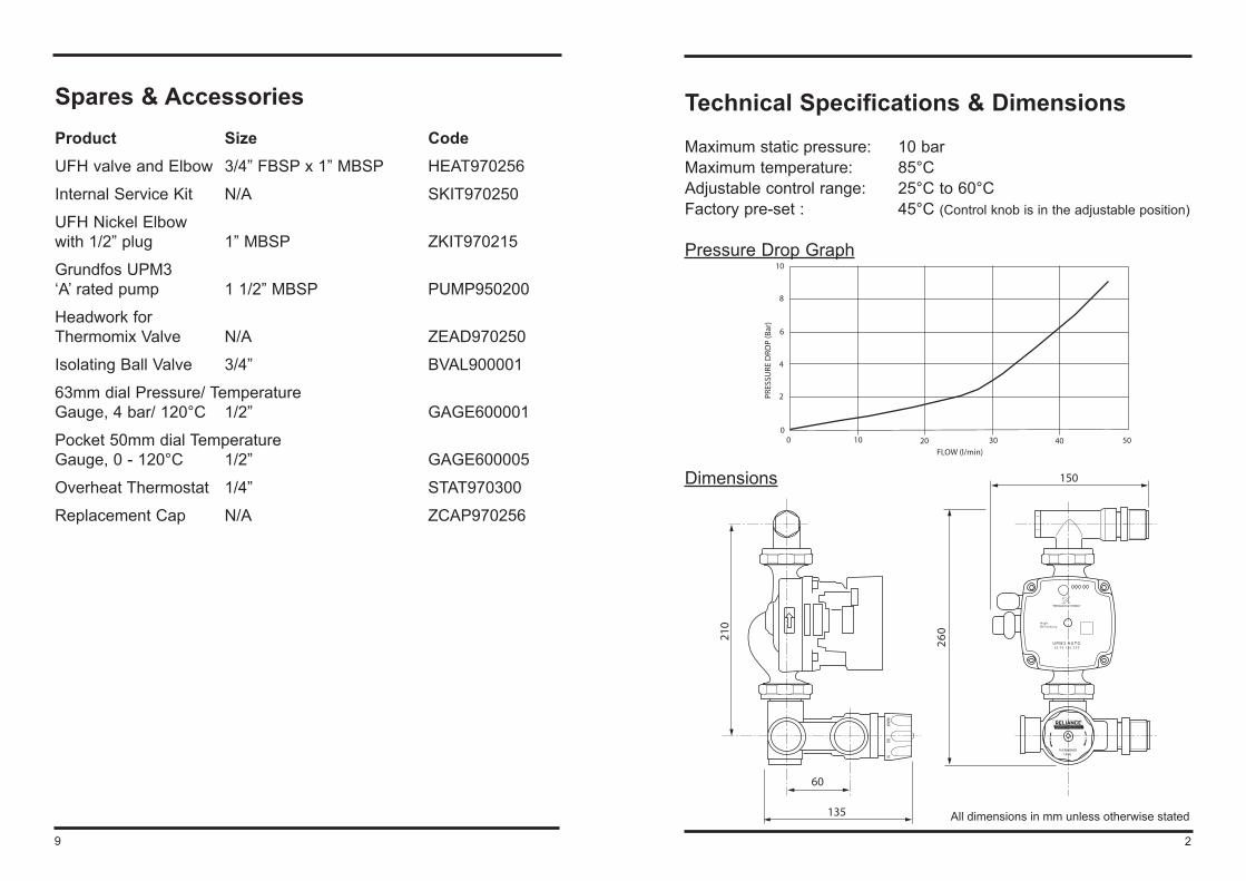
Technical Specifications & Dimensions
Maximum static pressure: 10 barMaximum temperature: 85°CAdjustable control range: 25°C to 60°CFactory pre-set : 45°C (Control knob is in the adjustable position)
Pressure Drop Graph
Dimensions
10 20 30 40 5000
2
4
6
8
10
FLOW (l/min)
PRES
SURE
DRO
P (B
ar)
2
H i g hE f f i c i e n c y
2 5 - 7 0 1 3 0 Z Z ZU P M 3 A U TO
THERMOMIXUFHL
210
150
60
135
260
All dimensions in mm unless otherwise stated
9
Spares & AccessoriesProduct Size CodeUFH valve and Elbow 3/4” FBSP x 1” MBSP HEAT970256
Internal Service Kit N/A SKIT970250
UFH Nickel Elbow with 1/2” plug 1” MBSP ZKIT970215
Grundfos UPM3 ‘A’ rated pump 1 1/2” MBSP PUMP950200
Headwork for Thermomix Valve N/A ZEAD970250
Isolating Ball Valve 3/4” BVAL900001
63mm dial Pressure/ TemperatureGauge, 4 bar/ 120°C 1/2” GAGE600001
Pocket 50mm dial TemperatureGauge, 0 - 120°C 1/2” GAGE600005
Overheat Thermostat 1/4” STAT970300
Replacement Cap N/A ZCAP970256
Pack ContentsPLEASE CHECK CONTENTS OF PACK BEFORE BEGINNING INSTALLATION.
Description, Part Number and Quantity
ThermoMix UFH Valve
Pump including rubber washers and cable
1’’ washers (Qty 2)
Pump nut
Connection elbow
3 8
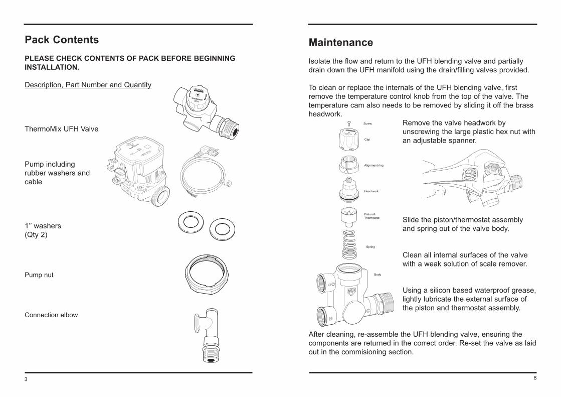
MaintenanceIsolate the flow and return to the UFH blending valve and partially drain down the UFH manifold using the drain/filling valves provided.
To clean or replace the internals of the UFH blending valve, first remove the temperature control knob from the top of the valve. The temperature cam also needs to be removed by sliding it off the brass headwork.
Remove the valve headwork by unscrewing the large plastic hex nut with an adjustable spanner.
Slide the piston/thermostat assembly and spring out of the valve body.
Clean all internal surfaces of the valve with a weak solution of scale remover.
Using a silicon based waterproof grease, lightly lubricate the external surface of the piston and thermostat assembly.
After cleaning, re-assemble the UFH blending valve, ensuring the components are returned in the correct order. Re-set the valve as laid out in the commisioning section.
Screw
Cap
Head work
Alignment ring
Piston &Thermostat
Spring
Body
IntroductionDesigned to work with manifolds of all types, on 210mm centres. The Thermomix Underfloor Heating Control Pack is a bolt on unit providing a quick and simple system to install.
InstallationFirstly firmly fix the distribution manifolds to the wall leaving enough room beside the manifold to fit the control pack (see dimensions on Page 2). Before beginning the installation of the Thermomix Underfloor Heating Control Pack, identify all of the components in the pack.
2.1The Thermomix UFH valve comes complete with a blanking plug, this means if the standard orientation of the kit is not suitable for your application you can unscrew the blanking plug and pump union (left handed thread), and change them around, to reverse the kit.
2.2Connect the Thermomix UFH valve to the pump using the pump nut which is pre-assembled to the thermomix, ensuring the pump washer is inserted. (taking note of the directional arrows on the pump body).
2.3Slip the 1 ½” pump nut over the flange on the flow connection elbow.
LEFTHAND
THREAD
LEFTHAND
THREAD
47
These intial settings can then be adjusted to provide the correct comfort level. A maximum floor surface temperature of 29°C should not be exceeded (with the exception of wet areas such as bathrooms, 35°C) as this may lead to feelings of discomfort.
With timber floor finishes including strip laminate products the maximum floor temperature of 27°C should not be exceeded as this may result in excessive shrinkage of the material. Maximum temperatures can vary so check the floor manufacturers recomendations first.
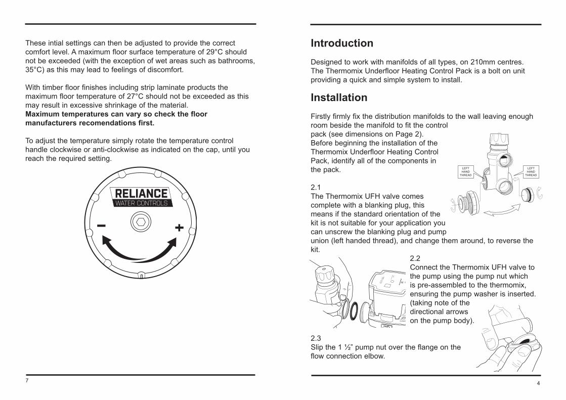
To adjust the temperature simply rotate the temperature control handle clockwise or anti-clockwise as indicated on the cap, until you reach the required setting.
6
WiringA fused spur should be provided adjacent to the manifold to provide power to the pump and two port zone valve if fitted.
To comply with IEE regulations, the pump on the Manifold Control Pack must be provided with an earth. All wiring should be undertaken by a qualified installer and must conform to IEE regulations.
CommissioningThe UFH valve supplied as part of the control pack has a temperature setting range of 25-60°C as indicated on the temperature adjustment cap: Min (25°C) 30ºC 35ºC 40ºC 45ºC 50ºC 55°C Max (60°C) The temperature control is factory set to 45°C with the cap in the adjustable position.
Initial setting of the thermostatic blending valve (after the heat up/screed drying period) should provide the following temperatures:
Screeded floors: 40-45°CTimber floors: 55-60°C
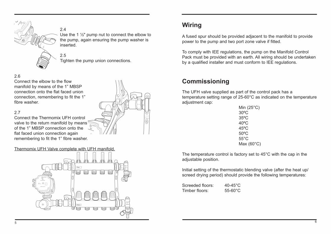
2.4Use the 1 ½" pump nut to connect the elbow to the pump, again ensuring the pump washer is inserted.
2.5Tighten the pump union connections.
2.6Connect the elbow to the flow manifold by means of the 1” MBSP connection onto the flat faced union connection, remembering to fit the 1” fibre washer.
2.7Connect the Thermomix UFH control valve to the return manifold by means of the 1” MBSP connection onto the flat faced union connection again remembering to fit the 1” fibre washer. Thermomix UFH Valve complete with UFH manifold.
H i g hE f f i c i e n c y
U P M 3 A U TO
Return
Flow
5