reliable world class insights your silicon valley partner ... · reliable world class insights your...
TRANSCRIPT

www.ozeninc.com [email protected] (408) 732 4665 1210 E Arques Ave St 207 Sunnyvale, CA 94085
Reliable World Class Insights
Your Silicon Valley Partner in Simulation
ANSYS Sales, Consulting, Training & Support

ELECTRIC VEHICLES
Fast- ChargingBattery Development
A view of internal mechanisms of lithium-ion battery pack used in Chevy Volt
Multiphysics simulation tools power the modeling of thermal management in advanced lithium-ion battery systems for electric vehicles.
© G
M C
ORP
.
ANSYS.COM © 2012 ANSYS, INC. ANSYS ADVANTAGE 11
W hen the electrically pow-ered “horseless carriage” of William Morrison, a Des
Moines, Iowa, chemist and inventor, was brought to widespread attention at the 1893 Chicago World’s fair, it proved to be hugely influential in early automo-tive history. Capitalizing on the new age of electricity that was being introduced, electric-drive vehicles powered by lead-acid storage batteries rose to mar-ket prominence over the next decade. Thousands of these vehicles were used to carry passengers around cities in North America and Europe. However, limitations of the battery technology combined with lack of recharging infra-structure ultimately led to waning popu-larity by the early 1910s.
Over the past century though, battery-specific energy (watt-hours/kilogram) has improved dramatically, with lithium-ion systems becoming the most popular
in recent years. With concern about emis-sions and the volatile price of gasoline, electric vehicles are again emerging as a viable transportation option, and the U.S. Department of Energy (DOE) is helping to sponsor innovative research to support the technology. One of the goals of DOE’s Vehicle Technologies Program for hybrid electric systems is to, by 2014, reduce the production cost of high-power batter-ies 70 percent from 2009 costs. In addi-tion, to encourage widespread adoption of electric vehicles, the industry must reduce the cost of high-energy batter-ies by a factor of three in the next sev-eral years. The use of battery simulation tools to design batteries and predict their performance is one of the strategies for hitting these targets.
To accelerate the production of safe, reliable, high-performance and long- lasting lithium-ion battery packs, the automotive industry requires simulation
tools that accurately represent cell and pack multiphysics phenomena occur-ring across a wide range of scales. In April 2010, the Vehicle Technologies Program launched the Computer-Aided Engineering for Electric Drive Vehicle Batteries (CAEBAT) activity through DOE’s National Renewable Energy Laboratory (NREL). In response to its own urgent demand for this technology as well as to the CAEBAT program championed by DOE/NREL, General Motors has assembled a project team composed of GM researchers and engineers, ANSYS software develop-ers, and the staff of ESim LLC.
The GM CAEBAT project has two main tasks: cell-level and pack-level design tools development. In partnership with NREL, the project team is working to identify end-user needs and establish requirements, integrate and enhance existing submodels, and perform experi-mental testing to validate the tools. In a third task, the team is creating interfaces to enable these new tools to interact with other current and future battery models.
BATTERY CELL MODELThe objective of the cell-level modeling tool is to predict multiphysics responses
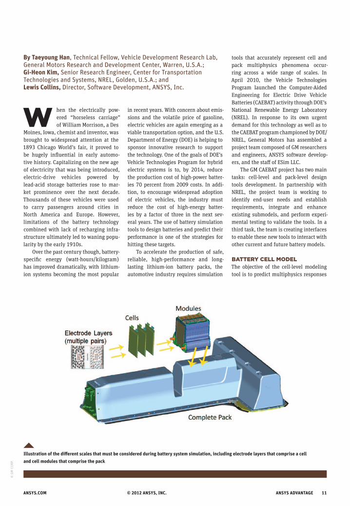
Illustration of the different scales that must be considered during battery system simulation, including electrode layers that comprise a cell and cell modules that comprise the pack.
By Taeyoung Han, Technical Fellow, Vehicle Development Research Lab, General Motors Research and Development Center, Warren, U.S.A.; Gi-Heon Kim, Senior Research Engineer, Center for Transportation Technologies and Systems, NREL, Golden, U.S.A.; and Lewis Collins, Director, Software Development, ANSYS, Inc.
© G
M C
ORP
.

12 ANSYS ADVANTAGE Volume VI | Issue 3 | 2012
of large-format (capacity greater than 5 amp-hours) lithium-ion battery cells. Because temperature greatly affects the performance, safety and life of lithium-ion batteries, automakers and battery suppliers are paying increased attention to thermal management to reduce tem-perature fluctuations. In a battery pack, heating and cooling can create uneven temperature distribution, which in turn leads to electrically unbalanced modules, thus lowering performance and short-ening battery life. For optimal operating conditions, temperature variations need to be minimized across each cell and between cells. If the temperature is too low, the power/energy output is reduced; if too high, cell life is limited.
The proposed cell-level model will provide a seamless connection among electrochemical, thermal and structural responses. The model will demonstrate to engineers how their design changes influence overall cell performance — that is, thermal, electric power, capac-ity, safety, state of charge and life — and internal imbalance within the cell due to spatial variations of current density and temperature. One-dimensional electrode-scale models have proven use-ful to understand the physics — such as electrochemical kinetics, lithium diffu-sion and transport, and charge conser-vation and transport — but a 3-D model is needed for realistic cell geometry that includes cell-level performance. The proj-ect team is collaborating with NREL for the scale coupling between 1-D electrode-scale models with the 3-D cell model.
Battery service life represents one of the greatest uncertainties in the
total lifecycle cost of electric-drive vehi-cles. The complex dependency of the cell capacity on time, temperature, volt-age, number of charge/discharge cycles, electrode microstructure, and depth of discharge is not fully understood and is often neglected in cell models. To simulate cell aging and degradation, the electrode-scale predictions will be enhanced by introducing models that account for capacity fade due to mechan-ical degradation caused by thermal and mechanical stress and loss of active material due to film formation.
BATTERY PACK MODELFrom an automotive OEM perspective, the primary value of battery compu-tational modeling tools is improving the battery pack’s thermal management, which affects many attributes. The goal of a battery thermal management system (TMS) is to maintain a battery pack at an optimum average temperature that oper-ates in surrounding environments rang-ing from -40 C to 50 C (-40 F to 122 F) and to minimize the temperature differ-ence in cells. Lithium-ion batteries oper-ate best at temperatures between 25 C and 35 C (77 F to 95 F), which is currently difficult or expensive to maintain over the wide range of environments expected during normal vehicle operation. Active cooling and heating of the battery pack is a challenge due to constraints on cost, power, weight and volume. Design solu-tions include heat sinks, air jet impinge-ment, micro-channel cooling, heat pipes, immersion cooling and spray cooling, so a simulation tool is needed for trade-off design studies.
At present, though, these concept evaluations and the resulting bat-tery life predictions are based on very time-consuming hardware build-and-test iterations — a process that could be streamlined by using effective pack-level simulation. The fastest way to cre-ate common cell and pack geometries for analysis is to use existing CAD models. For the team’s CAEBAT effort, the geom-etry interfaces capability within ANSYS Workbench is unsurpassed, and the software’s replication and parts-library functions will be helpful when geome-try and properties information must be input manually. The proposed approach is based on the Workbench platform and can handle complex 3-D geometry of
The model will demonstrate how engineering design changes influence overall cell performance.
Contours of velocity on mid-plane of a 20-cell module. In this example, water is being used as a coolant for the module, flowing in through the top channel and out the bottom channel.
ELECTRIC VEHICLES
Example geometry (left) and simulation boundary zones (right) of a generalized automotive battery module with 20 cells

ANSYS.COM © 2012 ANSYS, INC. ANSYS ADVANTAGE 13
The proposed approach is based on ANSYS Workbench and can handle complex 3-D geometry of battery cells.
The pack-level tool will combine field simulation from ANSYS Fluent and ANSYS Mechanical, and systems simulation using ANSYS Simplorer, through straightforward run-time coupling, or cosimulation.
battery cells, including current-collector tabs, encapsulation materials and struc-tural support details.
To solve electrochemical–thermal–fluid behavior at cell or module level, it may be appropriate to fully discretize the cell and coolant channels and per-form field simulation. However, direct scaling to the pack level is rarely prac-tical because it is computationally too demanding, particularly with the fluid dynamic complexity of some micro-chan-nel liquid cooling strategies now being considered. Efficient parallel code imple-mentation — a general strength of ANSYS solvers — is helpful in reducing execution times when high-performance comput-ing hardware is available. However, this strategy alone is insufficient, given the desire for rapid acceleration of battery- pack innovation and the associated number of pack-level simulations using conventional desktops and workstations.
Systems simulation offers a com-putationally inexpensive alternative, but the current state of the art relies on relatively uncoupled and simplistic cell representations, such as equivalent- circuit models. As battery power densi-ties increase and thermal issues become more complex, these system simulations have neither the reliability nor the reso-lution necessary to guide pack design. The pack-level tool will, thus, combine field simulation from ANSYS Fluent and ANSYS Mechanical, and systems simu-lation using ANSYS Simplorer, through straightforward run-time coupling, or cosimulation. Additionally, the team will develop innovative reduced-order models (ROMs) that enable field-simulation mod-els to be automatically distilled into a system model with a controllable balance between fidelity and cost.
OPEN-ARCHITECTURE SOFTWARE (OAS) INTERFACEThe project team will contribute to the OAS efforts, part of CAEBAT activity, led by Oak Ridge National Laboratory, and adopt specifications for input and output file formats and standard communication protocols. This will allow the team’s cell- and pack-level tools to exchange infor-mation with tools developed by other CAEBAT teams. The ANSYS Workbench environment and related solvers have anticipated the adaptive software archi-tecture needs; they have been devel-oped from the ground up with the tools and system services for customization as well as interoperability with other CAE players as diverse as Aspen Plus®, CATIA®, CHEMKIN®, Microsoft® Excel®, GT-POWER, Isight, MATLAB®/Simulink®, modeFRONTIER®, MSC Sinda®, TRASYS and SPICE.
ANSYS Workbench can be the back-bone of the entire battery-modeling workflow, and it can also connect peer to peer with other software environ-ments. The project team anticipates that this flexibility will be an asset as ANSYS develops the CAEBAT OAS interfaces and GM demonstrates the ability to select different battery models with different physics solvers and scales. The flexibil-ity will also be vital as GM integrates the newly developed tools into its proprie-tary process automation (PA) engineer-ing environment.
PROCESS AUTOMATION AND ROBUST ENGINEERINGGiven the complexity of the development process in a large organization like GM, it is important to ensure that the vari-ous models used for evaluation and opti-mization are correct and consistent; they
also must represent the most current design in the product development proc-ess. Complementary PA tools will follow after the project’s conclusion to enable rapid and reliable comparison of design alternatives, design exploration, robust assessments and optimization.
PA tools incorporate process guid-ance, which is useful for implement-ing enterprise-wide standardized work. Components of standardized work typically include following modeling guidelines, applying correct boundary conditions for analysis, post-processing and reporting analysis results. This standardized work is essential to assure decision makers that evaluation and reporting of analysis metrics is consis-tently performed. PA and robust engi-neering are proven methodologies in the automotive industry. GM has established these methodologies for the engineering areas of noise and vibration, crash anal-ysis, and body structural optimization. The battery design modeling tool devel-oped in this project can be coupled with a vehicle simulator to evaluate thermal and electrical responses of a particular battery pack for a given power load pro-file associated with a specified vehicle driving condition.
VERIFICATION AND VALIDATIONThe accuracy and usefulness of the pro-posed cell-level tool will be demonstrated through rigorous verification and vali-dation processes. GM will follow a math model validation process developed by the National Institute of Statistical Sciences (NISS). GM will generate the test database for physical verification of the nominal heat source model as
14 ANSYS ADVANTAGE Volume VI | Issue 3 | 2012
well as cell-level electrical and thermal performance.
The project team will use data from thermal characterization with known heat source and thermal boundary conditions for various battery TMS operation condi-tions. The total heat generated from the pack is calculated from coolant inflow and outflow rates and temperatures, sup-plemented by cell or module calorimetry and heat-generation measurement test-ing. Pack-level–specific heat and thermal conductivities are derived from individ-ual cell thermal properties and other elec-trical and electronic equipment onboard the pack. In addition, temperature sensors are placed at every module to monitor hot spots across the pack. This data is crucial for validating the coolant flow field around the battery pack.
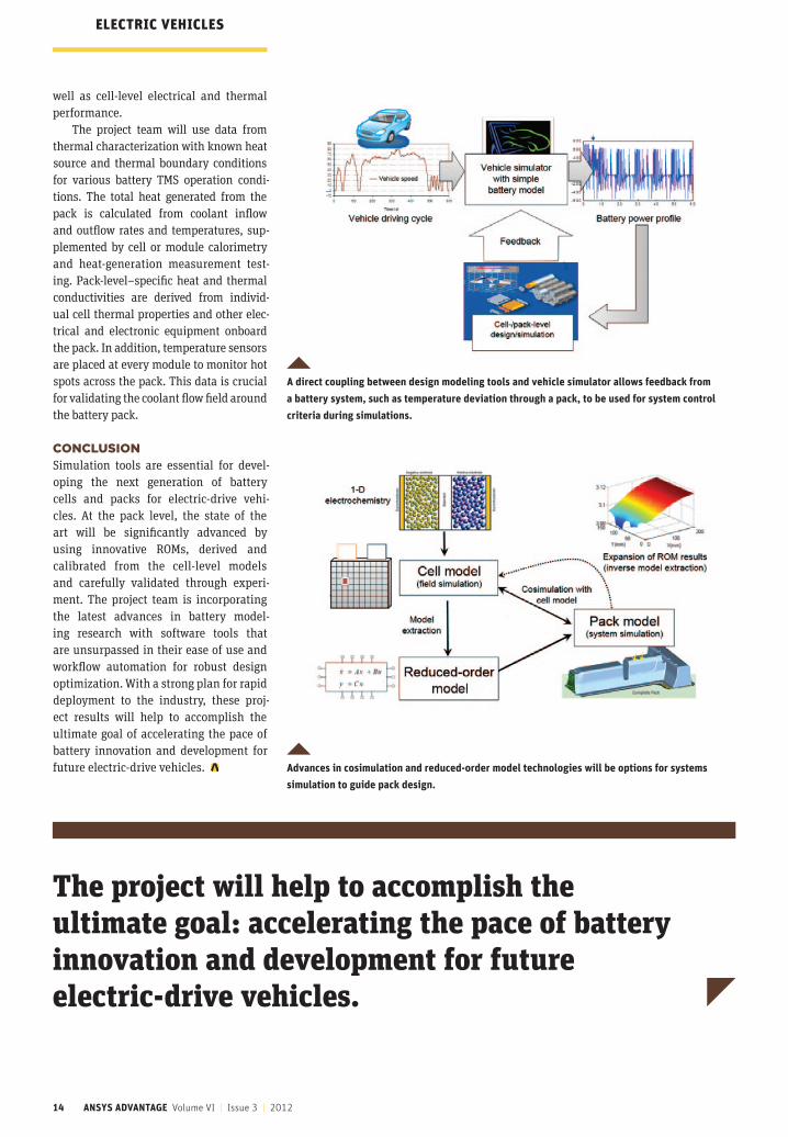
CONCLUSIONSimulation tools are essential for devel-oping the next generation of battery cells and packs for electric-drive vehi-cles. At the pack level, the state of the art will be significantly advanced by using innovative ROMs, derived and calibrated from the cell-level models and carefully validated through experi-ment. The project team is incorporating the latest advances in battery model-ing research with software tools that are unsurpassed in their ease of use and workflow automation for robust design optimization. With a strong plan for rapid deployment to the industry, these proj-ect results will help to accomplish the ultimate goal of accelerating the pace of battery innovation and development for future electric-drive vehicles.
The project will help to accomplish the ultimate goal: accelerating the pace of battery innovation and development for future electric-drive vehicles.
A direct coupling between design modeling tools and vehicle simulator allows feedback from a battery system, such as temperature deviation through a pack, to be used for system control criteria during simulations.
Advances in cosimulation and reduced-order model technologies will be options for systems simulation to guide pack design.
ELECTRIC VEHICLES