reliable symbols: decision-directed learning with quality control - winlab · verticalband...
TRANSCRIPT

VERTICALBAND TECHNOLOGY
Reliable Symbols:Decision-Directed Learning with
Quality ControlEilon Riess and Stuart SchwartzVerticalband Ltd. and Princeton
University

VERTICALBAND TECHNOLOGY
Higher Data Rates
• Higher data rates can be achieved by:– Shorter symbol length - more bandwidth,
more ISI– MIMO– More bits per symbol (higher order
constellation)
• Problem with HOC -- increases the ISI

VERTICALBAND TECHNOLOGY
Proposed Solution
• Use HOC to increase the data rate in conjunction with ‘Reliable Symbols’ to do blind equalization of HOC
• ‘Reliable Symbols’ greatly reduce (maybe eliminate) the need for training samples
• Can then track dynamic channels

VERTICALBAND TECHNOLOGY
HOC and Equalization
Observation: There is no known blind equalizer algorithm that works well with HOC!
J. J. Werner et al, “Blind Equalization for Broadband Access”, IEEECommunication Magazine, pp. 87-93, April 1997
J. R. Treichler et al, “Practical Blind Demodulators for High-Order QAM Signals,” Proceeedings of the IEEE, vol. 86, No. 10, pp. 1907-1926, October 1998
VERTICALBAND TECHNOLOGY
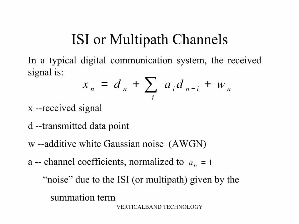
ISI or Multipath ChannelsIn a typical digital communication system, the received signal is:
x --received signal
d --transmitted data point
w --additive white Gaussian noise (AWGN)
a -- channel coefficients, normalized to
“noise” due to the ISI (or multipath) given by the
summation term
∑ ++= −i
nininn wdadx
10 =a

VERTICALBAND TECHNOLOGY
HOC is an ISI Amplifier
222222 )()( ISIadaEnE didiniISI σσ === ∑ ∑−
Look at the summation term:

VERTICALBAND TECHNOLOGY
Std of the ISI noise as a function of the constellation sizeISI= 1
1
3
5
7
9
11
13
15
17
19
2 4 8 16 32Constellation size [PAM]
STD

VERTICALBAND TECHNOLOGY
HOC and ISI
QPSK
16 QAM
64 QAM
256 QAM
VERTICALBAND TECHNOLOGY
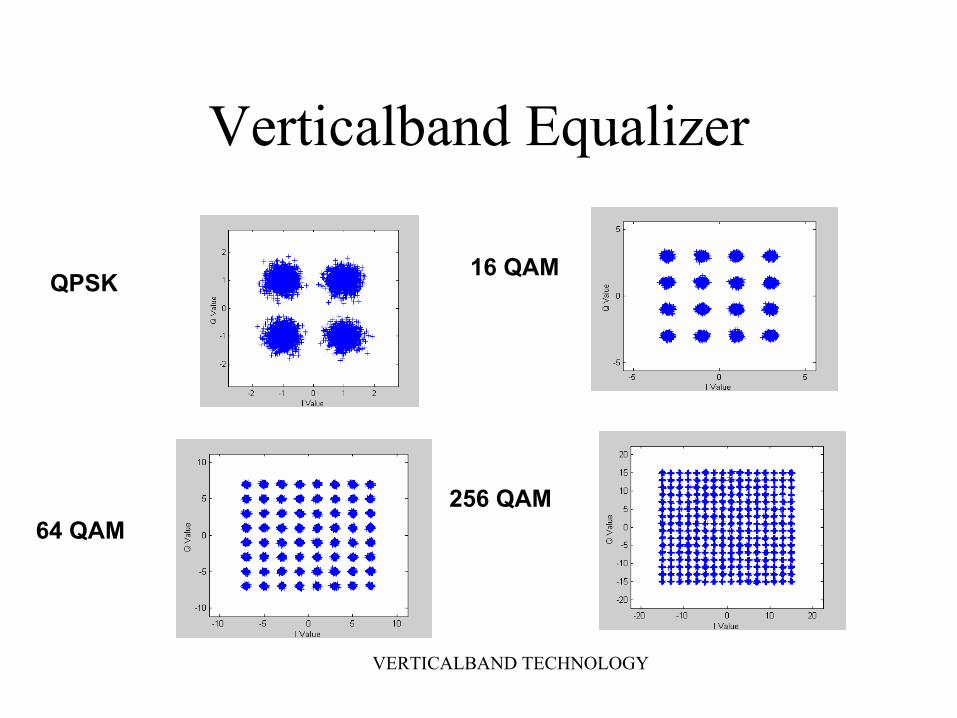
Verticalband Equalizer
QPSK 16 QAM
64 QAM256 QAM
VERTICALBAND TECHNOLOGY
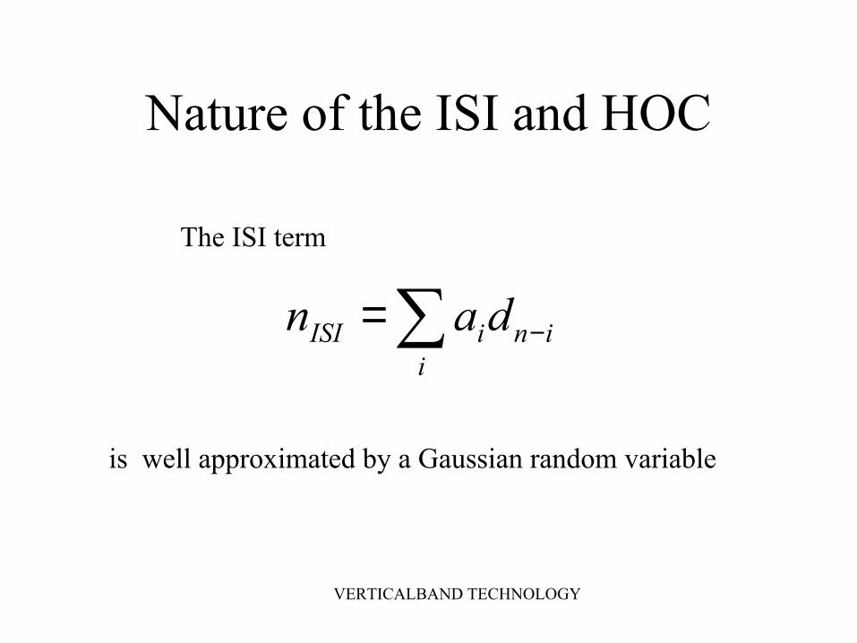
Nature of the ISI and HOC
∑ −=i
iniISI dan
The ISI term
is well approximated by a Gaussian random variable

VERTICALBAND TECHNOLOGY
The Gaussian Approximation
0
0.02
0.04
0.06
0.08
0.1
0.12
-6 -4 -2 0 2 4 6
ISI length 3Gaussian
1-1

VERTICALBAND TECHNOLOGY
True Symbols‘True Symbol’: is a received data point that is still located within its correct decision region despite the effects of ISI and the AWGN
nnn dx υ+=2222wd ISI σσσ
υ+=
Received signal and ‘noise’ variance is:

VERTICALBAND TECHNOLOGY
True Symbols‘True Symbol’: is a received data point that is still located within its correct decision region despite the effects of ISI and the AWGN
nnn dx υ+=2222wd ISI σσσ
υ+=
Received signal and ‘noise” variance is:
{ } ))2/(1(11Pr υσυ erfP nRS =<<−=
Probability of having a TS is:

VERTICALBAND TECHNOLOGY
The Gaussian Approximation
0
0 .0 2
0 .0 4
0 .0 6
0 .0 8
0 .1
0 .1 2
-6 -4 -2 0 2 4 6
IS I le n g th 3G a u ssia n
1-1

VERTICALBAND TECHNOLOGY
• Sometimes the interference is low and the received data point is located within its correct decision region. In this case the received symbol is actually a True Symbol.
Decision region for symbol
Noise effecting the transmitted symbolReceived data point
Problem: The receiver sees onlyxn = dn + noise
Question: Is it possible to determine if a received data point is actually a True Symbol
Answer: YES, with a high probability
Solution: Reliable Symbols
x

VERTICALBAND TECHNOLOGY
Reliable Symbols
‘Reliable Symbol’: is a received data point whose surrounding symbols have energies that are below a pre-defined threshold and are therefore unlikely to contribute a great deal of ISI.
RELIABLE SYMBOLS ARE , THEREFORE, HIGHLY LIKELY TO BE ‘TRUE SYMBOLS’.

VERTICALBAND TECHNOLOGY
Finding Reliable Symbols - 1∑ ++= −
inininn wdadx
∑∑∑ ≤≤= −− iiniiniISI addadan max
We can bound the ISI:
For initial ISI < 1, easy to define low energy signals

VERTICALBAND TECHNOLOGY
Finding Reliable Symbols - 2
KRS MP )/2(=
PAM constellation of order M,with data at +-1, +-3, +-5, ... Define a low energy signal as having magnitude = 1.
With K surrounding symbols (pre-cursors and post cursors) of low energy, probability of such a sequence is:

VERTICALBAND TECHNOLOGY
Finding Reliable Symbols - 3
Define a reliable symbol weight (RSW) which is monotonically decreasing with magnitude of hard decision on surrounding symbols:
−= ∑=
−
N
iinn dC
CRSW
1
^1
Choose C so that 0<RSW<1

VERTICALBAND TECHNOLOGY
Reliable Symbol Simulation - 1
8-PAM constellation
Normalized SNR = 16dB
20,000 received points in the simulation
ISI coefficients: (1, 0.4, 0.2, 0.1)
7,5,3,1 ±±±±=nd

VERTICALBAND TECHNOLOGY
Soft decision error vs. RS weights

VERTICALBAND TECHNOLOGY
Probability of correct decision vs. RS weights
VERTICALBAND TECHNOLOGY
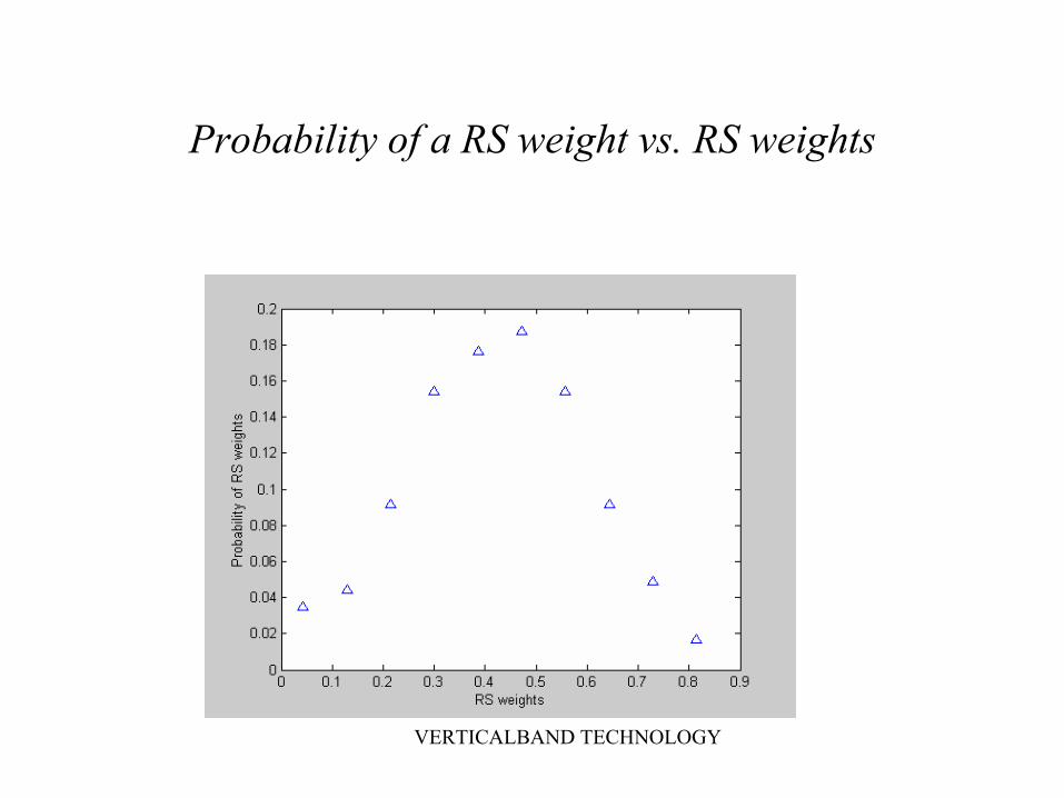
Probability of a RS weight vs. RS weights

VERTICALBAND TECHNOLOGY
Simulation 1--Summary8-PAM constellation
Normalized SNR = 16dB
20,000 received points in the simulation
ISI coefficients: (1, 0.4, 0.2, 0.1)
Note: 1. With a RSW > 0.8, RS can be identified with Prob. =1.
2. One RS can be detected in about every
59 received signals

VERTICALBAND TECHNOLOGY
Reliable Symbol Simulation - 2
32-PAM constellation
Normalized SNR = 16dB
Received signal points = 30,000
ISI coefficients: (1, 0.3, 0.1, 0.05)
31,...,3,1 ±±±=nd

VERTICALBAND TECHNOLOGY
Soft decision error vs. RS weights

VERTICALBAND TECHNOLOGY
Probability of correct decision vs. RS weights

VERTICALBAND TECHNOLOGY
Probability of a RS weight vs. RS weights

VERTICALBAND TECHNOLOGY
Simulation 2 -- Summary32-PAM constellation
SNR = 16dB
Received signal points = 30,000
ISI coefficients: (1, 0.3, 0.1, 0.05)
Note: 1. With a RSW >0.95, a RS can be identified with Prob. = 1.
2. For RSW > 0.95, Prob. 0.00035
One RS in about 3000 received signals
≈

VERTICALBAND TECHNOLOGY
Subtractive Equalizer
Rather than work with received data, we “rescatter” by subtracting our best estimate of the ISI:
ini
inn daxy −∑−=^^
A DFE without a linear feedforward filter

VERTICALBAND TECHNOLOGY
RSD- EqualizerDecision
Device
Subtractive
Equalizer
Channel EstimatorRSD
nx nd^
ny
^
ia

VERTICALBAND TECHNOLOGY
• Express the rescattered data point, yn, in terms of the Tx symbol, estimated Txsymbols, and the estimated channel coefficients:
Error in Tx Symbol
Rescattered Data Point
Estimated Channel Coefficient
Decision errorsDecision errorsChannel estimation errorsChannel estimation errors
Tx Symbols
Channel Coefficients
WGN
∑=
− ++=N
iGininn ndadx
1iii aaa ~ˆ +=iii ddd −=
^~
∑=
−−=N
iininn daxy
1
ˆˆ
∑ ∑= =
−− +−−=N
iG
N
iiniininn ndadady
1 1
~~

VERTICALBAND TECHNOLOGY
RSD in the Subtractive Equalizer
M is m a tc h E q u a l is e rL S E s t im a to r
nx
∑=
−⋅−′=N
iininn dayy
1
ˆ
ny
nd̂
Na 1}ˆ{
1}ˆ{ −− Nd
M e m o r y ( s iz e L )
HW ∆
M e m o r y ( S iz e L )
S in g le e le m e n t
V e c to r
M a t r ix
{ } 1ˆ −
− Nnd
{ }nd
t i o nI n i t i a l i s a
R S D
H a r d D e c is io n
S ig n a l in

VERTICALBAND TECHNOLOGY
LS Channel Estimator
is nxk, rows contain k surrounding signals
W is a weighting matrix
After about 10 reliable symbols:
^
nn dx −=∆
∆= − WDDWDa TT ˆ)ˆˆ( 1^
D̂

VERTICALBAND TECHNOLOGY
LS Channel Estimation(Single Batch Processing)
Constellation Channel Number of surrounding symbols
Sample size
RS min
RS max
aaverage ˆ aStd ˆ
8-PAM 1 2+1 750 8 18 0.301 0.099
0.0044 0.0082
8-PAM 1 2 750 50 57 0.307 0.089
0.019 0.029
8-PAM 1 2 200 7 18 0.3114 0.0969
0.0383 0.0479
16-PAM 1 2+1 6000 7 18 0.301 0.1007
0.0034 0.003
16-PAM 1 2 6000 82 114 0.287 0.0486
0.0314 0.0306
16-PAM 1 2 2000 20 38 0.27 0.069
0.05 0.052
32-PAM 1 2+1 45000 8 18 0.2892 0.0029
0.0811 0.04
32-PAM 1 2+1 30000 5 15 0.344 0.0028
0.07 0.085
8-PAM 2 2+3 20000 18 24 0.474 0.244
0.026 0.017
Simulation results summary table for channel, 1. 1, 0.3, 0.12. 1, 0.5, 0.25

VERTICALBAND TECHNOLOGY
0
0.1
0.2
0.3
0.4
0.5
0.6
0.7
0 10000 20000 30000 40000 50000 60000
Symbols
Estim
ated
taps
Adaptive Batch Estimation and Subtractive Equalization - 1
32 PAM, ISI: 1, 0.6, 0.5Initial Estimate: 0.3, 0.25

VERTICALBAND TECHNOLOGY
0
0.1
0.2
0.3
0.4
0.5
0.6
0.7
0 2000 4000 6000 8000 10000 12000
Symbols
Estim
ated
taps
Adaptive Batch Estimation and Subtractive Equalization - 2
8 PAM, ISI: 1, 0.6, 0.4, 0.3Initial Estimate: 0.4, 0.2, 0.1
VERTICALBAND TECHNOLOGY
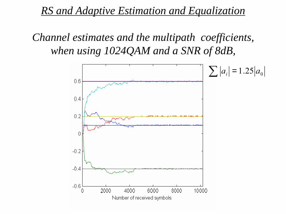
RS and Adaptive Estimation and Equalization
Channel estimates and the multipath coefficients, when using 1024QAM and a SNR of 8dB,
025.1 aai =∑
VERTICALBAND TECHNOLOGY
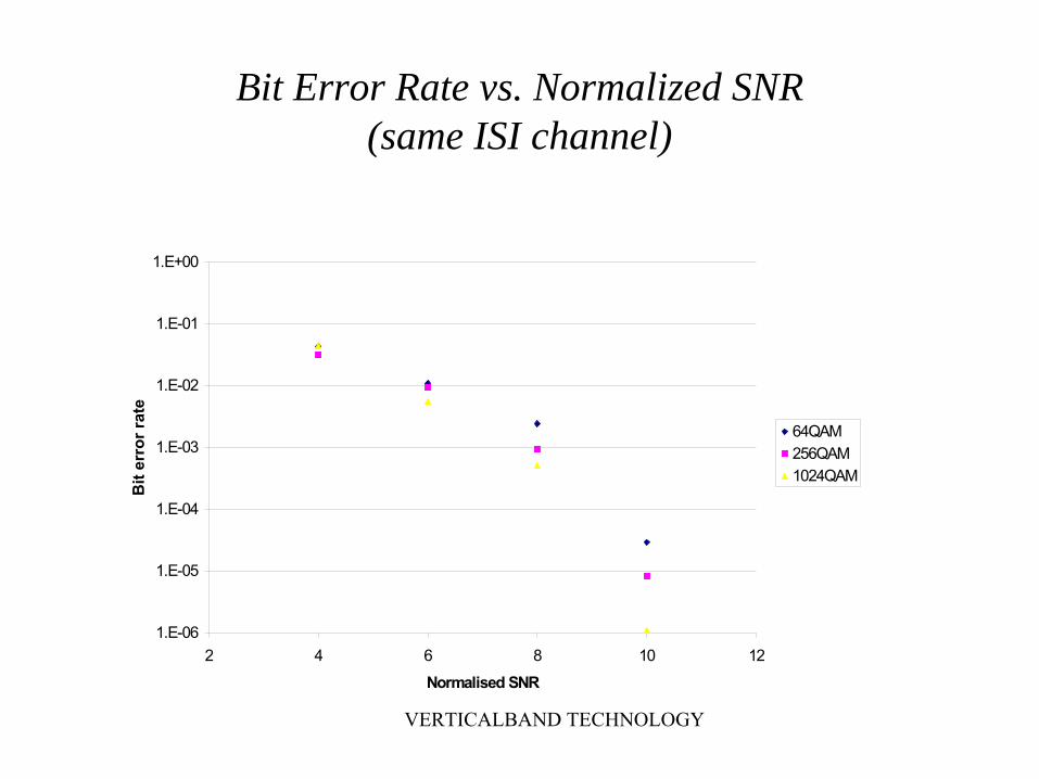
Bit Error Rate vs. Normalized SNR(same ISI channel)
1.E-06
1.E-05
1.E-04
1.E-03
1.E-02
1.E-01
1.E+00
2 4 6 8 10 12Normalised SNR
Bit
erro
r rat
e
64QAM256QAM1024QAM

VERTICALBAND TECHNOLOGY
Channel Estimation
0
8
135.1 aa
ii =∑
=
Randomly selected 8 coefficient multipath channel with closed binary eye:
Normalized SNR = 12dB
Constellation Samples required
to estimate channel
64QAM 3000 symbols
256 5000
1024 12000
4096 20000

VERTICALBAND TECHNOLOGY
Channel estimates of multipath coefficients, for 4096QAM and SNR of 12dB, (35.57 SNR)

VERTICALBAND TECHNOLOGY
The error distance when using 4096QAM and the SNR equals 12 dB
VERTICALBAND TECHNOLOGY
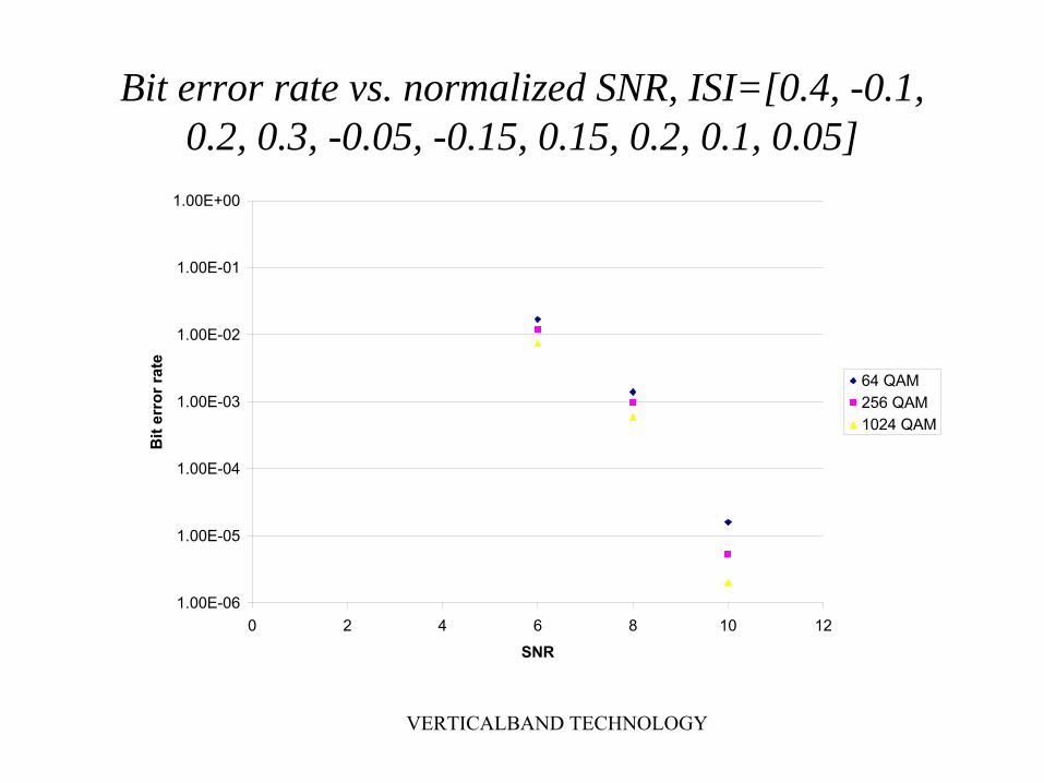
Bit error rate vs. normalized SNR, ISI=[0.4, -0.1, 0.2, 0.3, -0.05, -0.15, 0.15, 0.2, 0.1, 0.05]
1.00E-06
1.00E-05
1.00E-04
1.00E-03
1.00E-02
1.00E-01
1.00E+00
0 2 4 6 8 10 12SNR
Bit
erro
r rat
e
64 QAM256 QAM1024 QAM

VERTICALBAND TECHNOLOGY
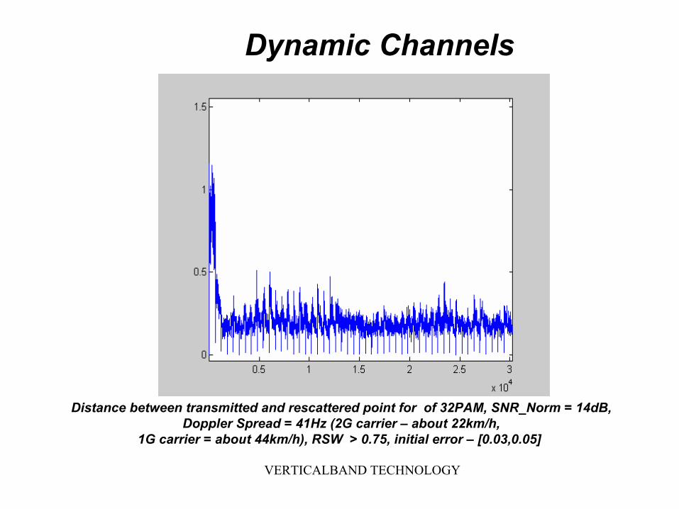
Dynamic Channels
Distance between transmitted and rescattered point for 16 PAM, SNR_Norm = 14dB, Doppler Spread = 125Hz (2G carrier – about 67km/h, 1G carrier = about 134km/h), RSW >
0.6, initial error – [0.05,0.07]
I
VERTICALBAND TECHNOLOGY
Distance between transmitted and rescattered point for of 32PAM, SNR_Norm = 14dB,Doppler Spread = 41Hz (2G carrier – about 22km/h,
1G carrier = about 44km/h), RSW > 0.75, initial error – [0.03,0.05]
Dynamic Channels
VERTICALBAND TECHNOLOGY
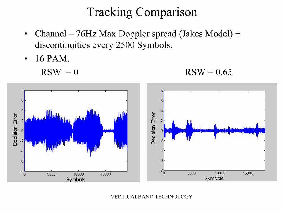
Tracking Comparison• Channel – 76Hz Max Doppler spread (Jakes Model) +
discontinuities every 2500 Symbols.• 16 PAM.
RSW = 0 RSW = 0.65

VERTICALBAND TECHNOLOGY
Application Areas
• Mobile Wireless• Fixed Wireless• Digital TV• DSL

VERTICALBAND TECHNOLOGY
Conclusions
• Reliable symbols – the “next best thing to training samples”
• Subtractive equalizer – accelerates the convergence process
-- Get RS with increasing frequency-- Can track dynamic channels
• Combine the two concepts for a blind equalizer that converges rapidly for HOC

VERTICALBAND TECHNOLOGY
Future Work• Coded systems• PSK modulation• Better channel estimators using RS• Study a variety of RSW• Relationship to turbo-equalization and other
iterative methods that compute and use posterior probabilities
• MIMO and QAM – are they a good fit• Follow up on good suggestions from colleagues in
the audience

VERTICALBAND TECHNOLOGY
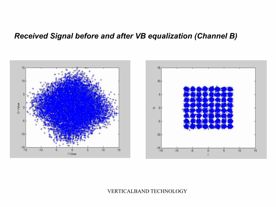
Channel B:
Complex Channel
VERTICALBAND TECHNOLOGY
Received Signal before and after VB equalization (Channel B)

VERTICALBAND TECHNOLOGY
Dynamic Channels - 1• 64 QAM – VB Tracking (SNR=15dB, Doppler Spread =
50Hz, Symbol rate = 1.2288MSym/Sec)
Channel variation and VB tracking. Four real and four imaginary channel coefficients.
I

VERTICALBAND TECHNOLOGY
256 QAM – VB Tracking (SNR=20dB, Doppler = 50Hz, Symbol rate = 1.2288MSym/Sec)
Channel variation and VB tracking. Four real and four imaginary channel coefficients.
I Q
Dynamic Channels -2

VERTICALBAND TECHNOLOGY
Dynamic Channels - 3Variation SNR Constellation Order
ISI= 1.25
0.05/90 samples 10dB 64QAM
0.05/400 10dB 256
0.05/4000 10dB 1024
ISI=.65
0.05/400 14dB 1024
0a
0a

VERTICALBAND TECHNOLOGY
Effect of HOC
4QAM
16QAM
64QAM
256QAM
1024QAM
1
10
100
1000
1 10 100 1000 10000Constellation size [Log]
STD
[Log
]

VERTICALBAND TECHNOLOGY
A generic system with a RSD and channel estimator and decoder.
M E M O R Y
C A P T U R E DS A M P L EB U F F E R
D E M O D U L A T O R
D E C O D E DS Y M B O LB U F F E R
R E L I A B L ES Y M B O L
D E T E C T O R
S Y M B O LD E C O D E R
I S IE S T I M A T O R
x n x n
d̂ n
P R O G R A MI N S T R U C T I O N S
P R O C E S S O R
D a t a o u t

VERTICALBAND TECHNOLOGY
High Data Rates (ISI)MobilityMobility
Today’s voice-enabled networks are transitioning
to 2.5 and 3G data-enabled networks
Today’s voice-enabled networks are transitioning
to 2.5 and 3G data-enabled networks
Broadband AccessBroadband Access
LMDS, MMDS and other broadband access
networks are providing scalable alternatives to
incumbent networks
LMDS, MMDS and other broadband access
networks are providing scalable alternatives to
incumbent networks
Digital Television promises a world of High-Definition video
coupled with High-Fidelity audio
Digital Television promises a world of High-Definition video
coupled with High-Fidelity audio
Digital TelevisionDigital Television
Cable
TerrestrialBroadcast
Satellite