reliable small cell planning using lte test transmitter ... · for such critical areas during the...
TRANSCRIPT

Reliable small cell planning using LTE test transmitter Application Note
Products:
ı R&S®SGT100A
ı R&S®TSME
ı R&S®ROMES4
Reliable small cell planning is essential for important deployments like hospitals, manufacturing facilities,
simply VIP (CxO) office floors or meeting rooms (the list of examples is endless). Often planning tools do
not provide this high reliability and required accuracy.
Rohde & Schwarz offers a solution that helps verifying the indoor small cell planning for such critical areas
during the site survey by using a test transmitter at the planned small cell position and really measuring the
performance (coverage and capacity). The site survey gets more reliable and ensures that the small cell
deployment will deliver the expected performance.
This application note is a simple step-by-step guide that introduces a practical method to perform reliable
small cell planning.
Note:
Please find the most up-to-date document on our homepage http://www.rohde-
schwarz.com/appnote/1MA297.
This document is complemented by software. The software may be updated even if the version of the
document remains unchanged
App
licat
ion
Not
e
Sam
uel T
rette
r
1.20
17 –
1M
A29
7_0e

Table of Contents
1MA297_0e Rohde & Schwarz Reliable small cell planning using LTE test transmitter
2
Table of Contents
1 Introduction ......................................................................................... 3
2 General Procedure .............................................................................. 4
3 Setup .................................................................................................... 5
3.1 Hardware setup ............................................................................................................ 5
3.2 Software setup ............................................................................................................. 6
3.3 Connecting the transmitter ......................................................................................... 6
3.4 Connecting the scanner .............................................................................................. 7
3.5 Transmitting the signal .............................................................................................10
3.6 Starting the measurement ........................................................................................11
4 Analysis of the measurement results ............................................. 13
4.1 Automatic Channel Detection view ..........................................................................13
4.2 LTE scanner view.......................................................................................................13
4.3 Spectrum view ............................................................................................................15
5 Interpretation of measurement results ........................................... 16
6 Ordering Information ........................................................................ 17

Introduction
1MA297_0e Rohde & Schwarz Reliable small cell planning using LTE test transmitter
3
1 Introduction
Mission- or even safety-critical small cell deployments require a highly reliable and
accurate planning. Examples might be hospitals, manufacturing facilities, simply VIP
(CxO) office floors or meeting rooms; the list of examples is endless. Often planning
tools do not provide this high reliability since e.g. floor plans might be outdated or
changes in real deployments are not maintained properly in the plans.
Rohde & Schwarz offers a solution that helps verifying the indoor small cell planning
for such critical areas during the site survey by using a test transmitter at the planned
small cell position and really measuring the performance (coverage and capacity). The
site survey gets more reliable and ensures that the small cell deployment will deliver
the expected performance.
The very compact and lightweight test transmitter R&S®SGT100A is able to generate
all kinds of modulated signals. To measure the resulting performance we offer a
network scanner (out of our scanner family R&S®TSME, R&S
®TSMA, R&S
®TSMW)
that provides the radio parameters with very high accuracy. RSRP and SINR for LTE
will be measured and from SINR the capacity of the new planned small cell can be
derived qualitatively. The interpretation of the measurement results can be found in
chapter 5.
This application note is a simple step-by-step guide that introduces a practical method
to perform reliable small cell planning.
General Procedure
1MA297_0e Rohde & Schwarz Reliable small cell planning using LTE test transmitter
4
2 General Procedure
The planning process of an indoor installation needs a record of the actual situation
without the planned small cell. To get this data simply do a measurement without the
test transmitter (see chapters 3.4, 3.6 and 4). As a result you will typically get signals
with low RSRP (Reference Signal Receive Power) and SINR (Signal to Interference
and Noise Ratio) performance indicators. The RSRP value gives an indication of
coverage at the measurement position, SINR value is a measure of the signal quality in
relation to the interference. With bad coverage and low signal quality only a low data
throughput can be expected.
Now start the test transmitter (see complete chapters 3 and 4) to emulate an LTE
installation. It's important to use the correct band for the intended small cell
deployment. Please be aware that you are transmitting in licensed bands (that might
belong to another operator) even if the test duration is very limited, so ideally use the
frequency that is owned by the operator who intends to install a small cell.
Again measure the band(s) with the scanner to get the performance indicators for the
test transmitter. You will get even with low transmit power much better RSRP and
SINR values.
A more in-depth interpretation of the SINR can be found in chapter 5.

Setup
1MA297_0e Rohde & Schwarz Reliable small cell planning using LTE test transmitter
5
3 Setup
3.1 Hardware setup
For the test setup you need the following parts:
ı 2 notebooks
ı 2 network cables
ı 1 R&S®SGT100A incl. K255 (LTE option), K510 (ARB baseband generator
32Msamples, 60MHz RF bandwidth)
ı 1 R&S®TSME incl. K29 (LTE scanning) (Alternatively TSMA or TSMW)
ı 1 R&S®ROMES4 license USB stick, R&S®ROMES4ACD (Automatic Channel
Detection)
ı 2 antennas with SMA connector for the relevant frequency bands
The demo setup consists of two separate stations. One transmits the LTE-signal into
the air. The other detects and measures the signal to give an idea of the performance
of a planned small cell system.
The transmitter station should be built up this way:
The measurement station should be built up this way:
Notebook R&S®SGT100A Antenna LAN SMA
Notebook Antenna R&S®TSME LAN SMA
Setup
1MA297_0e Rohde & Schwarz Reliable small cell planning using LTE test transmitter
6
3.2 Software setup
For the transmitter station the following software has to be installed on the notebook:
ı R&S®SGMA-GUI
ı R&S®WinIQSIM2
ı R&S®VISA
ı One of the LTE waveform files, which are provided with this application note (One
has 10 MHz bandwidth, the other has 20 MHz. Frequency and transmit power are
set up at chapter 2.5)
The measurement station needs the following software installed on its notebook:
ı R&S®ROMES4
3.3 Connecting the transmitter
After the demo setup is built up and the software is installed the network connections
have to be configured. To avoid errors deactivate all network adapters apart from your
LAN interface.
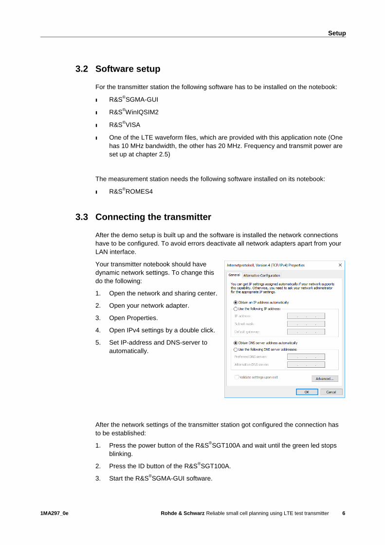
Your transmitter notebook should have
dynamic network settings. To change this
do the following:
1. Open the network and sharing center.
2. Open your network adapter.
3. Open Properties.
4. Open IPv4 settings by a double click.
5. Set IP-address and DNS-server to
automatically.
After the network settings of the transmitter station got configured the connection has
to be established:
1. Press the power button of the R&S®SGT100A and wait until the green led stops
blinking.
2. Press the ID button of the R&S®SGT100A.
3. Start the R&S®SGMA-GUI software.
Setup
1MA297_0e Rohde & Schwarz Reliable small cell planning using LTE test transmitter
7
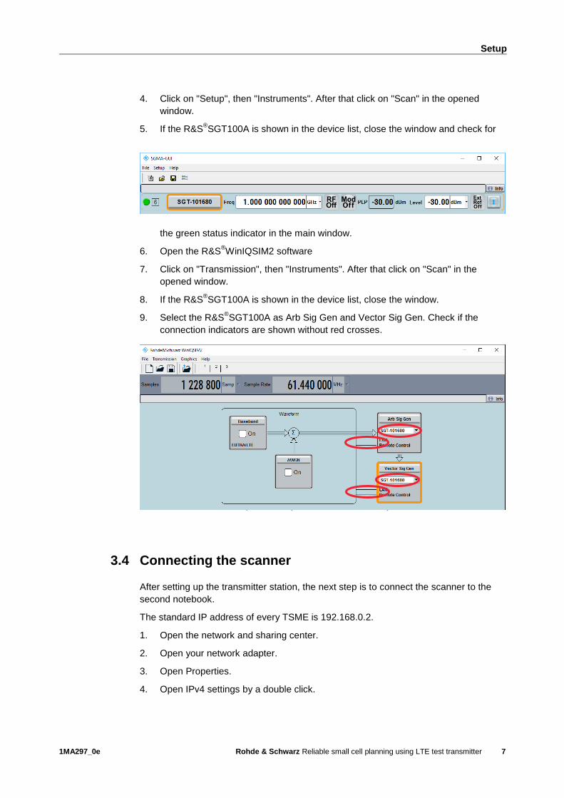
4. Click on "Setup", then "Instruments". After that click on "Scan" in the opened
window.
5. If the R&S®SGT100A is shown in the device list, close the window and check for
the green status indicator in the main window.
6. Open the R&S®WinIQSIM2 software
7. Click on "Transmission", then "Instruments". After that click on "Scan" in the
opened window.
8. If the R&S®SGT100A is shown in the device list, close the window.
9. Select the R&S®SGT100A as Arb Sig Gen and Vector Sig Gen. Check if the
connection indicators are shown without red crosses.
Next step is to configure the network settings of the second notebook for the
measurement station:
1. Open the network and sharing center.
2. Open your network adapter.
3. Open Properties.
4. Open IPv4 settings by a double click.
5. Set IP-address to static and enter 192.168.0.1. Your subnet mask is
255.255.255.0. Select manual DNS-server but don't enter anything. This settings
work if your R&S®TSME is configured with the default network settings (IP
address 192.168.0.2). If not, adjust the IP address for your notebook.
3.4 Connecting the scanner
After setting up the transmitter station, the next step is to connect the scanner to the
second notebook.
The standard IP address of every TSME is 192.168.0.2.
1. Open the network and sharing center.
2. Open your network adapter.
3. Open Properties.
4. Open IPv4 settings by a double click.
Setup
1MA297_0e Rohde & Schwarz Reliable small cell planning using LTE test transmitter
8
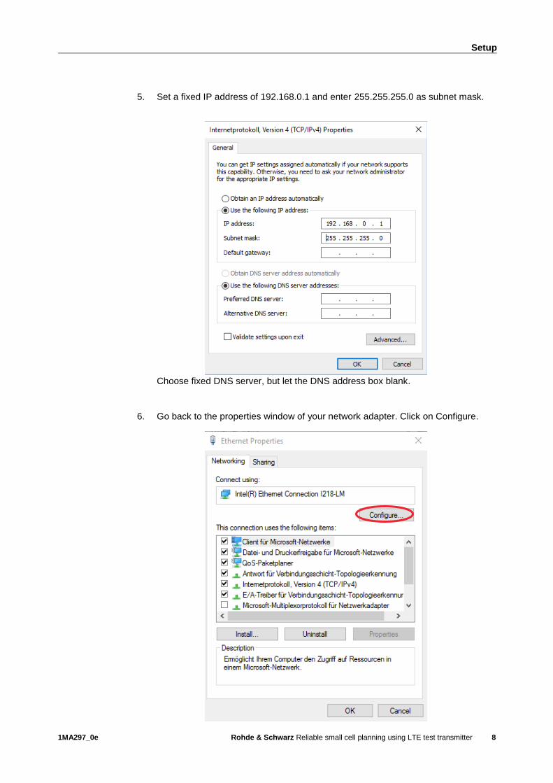
5. Set a fixed IP address of 192.168.0.1 and enter 255.255.255.0 as subnet mask.
Choose fixed DNS server, but let the DNS address box blank.
6. Go back to the properties window of your network adapter. Click on Configure.

Setup
1MA297_0e Rohde & Schwarz Reliable small cell planning using LTE test transmitter
9
7. Go to the Advanced tab. Set the jumbo packets to "9014 Bytes".
8. Close all dialog boxes and start R&S®ROMES4. If the connections works, the
software shows the functions of your TSME at the bottom of the welcome page. If
the connection isn't established correctly, only "Add Device Manually" and "Indoor
Navigation" are visible.
9. If the firewall settings have not been defined to include the R&S TSME
applications (connection for the first time), a Windows Security Alert may appear.
Change the firewall settings to permit access to the R&S TSME applications:
a) In the Windows Control Panel, select "System and Security > Windows Firewall

Setup
1MA297_0e Rohde & Schwarz Reliable small cell planning using LTE test transmitter
10
> Allow programs to communicate through Windows Firewall".
b) Allow the specified application module(s) to communicate on all three network
types (domain, private, public). In particular, select:
- TSME Device Manager Application
- tsmeping
3.5 Transmitting the signal
1. Go to the R&S®WinIQSIM2 main window.
2. Click on "Transmission", then "Transmit". Select "File" as source and open the
provided waveform file. Select "Instrument" as destination and insert a file name
to save it on the internal memory of the R&S®SGT100A.
3. Press "Transmit Waveform".
4. Go to the R&S®SGMA-GUI main window. Expand the settings of the connected

Setup
1MA297_0e Rohde & Schwarz Reliable small cell planning using LTE test transmitter
11
R&S®SGT100A. Check if the at step 2 entered file name is shown.
5. Enter the center frequency and the signal power. Attention: Keep your signal's
power low at a maximum of 10 dBm to avoid interfering real networks outside the
building. Depending on the use case the typical indoor small cell transmit power is
in the range of 10 … 25 dBm. A measurement with 10 dBm transmit power gives
the required reference result (SINR). The targeted SINR can be scaled up with the
transmit power (a 10 dB higher transmit power should result in a 10 dB higher
SINR as a feasible approximation).
6. Switch on the modulation and the RF generator.
3.6 Starting the measurement
1. Click on "Automatic Channel Detection" at the bottom of the main window of
R&S®ROMES4 and click yes, when you get asked to use a new workspace.
Setup
1MA297_0e Rohde & Schwarz Reliable small cell planning using LTE test transmitter
12
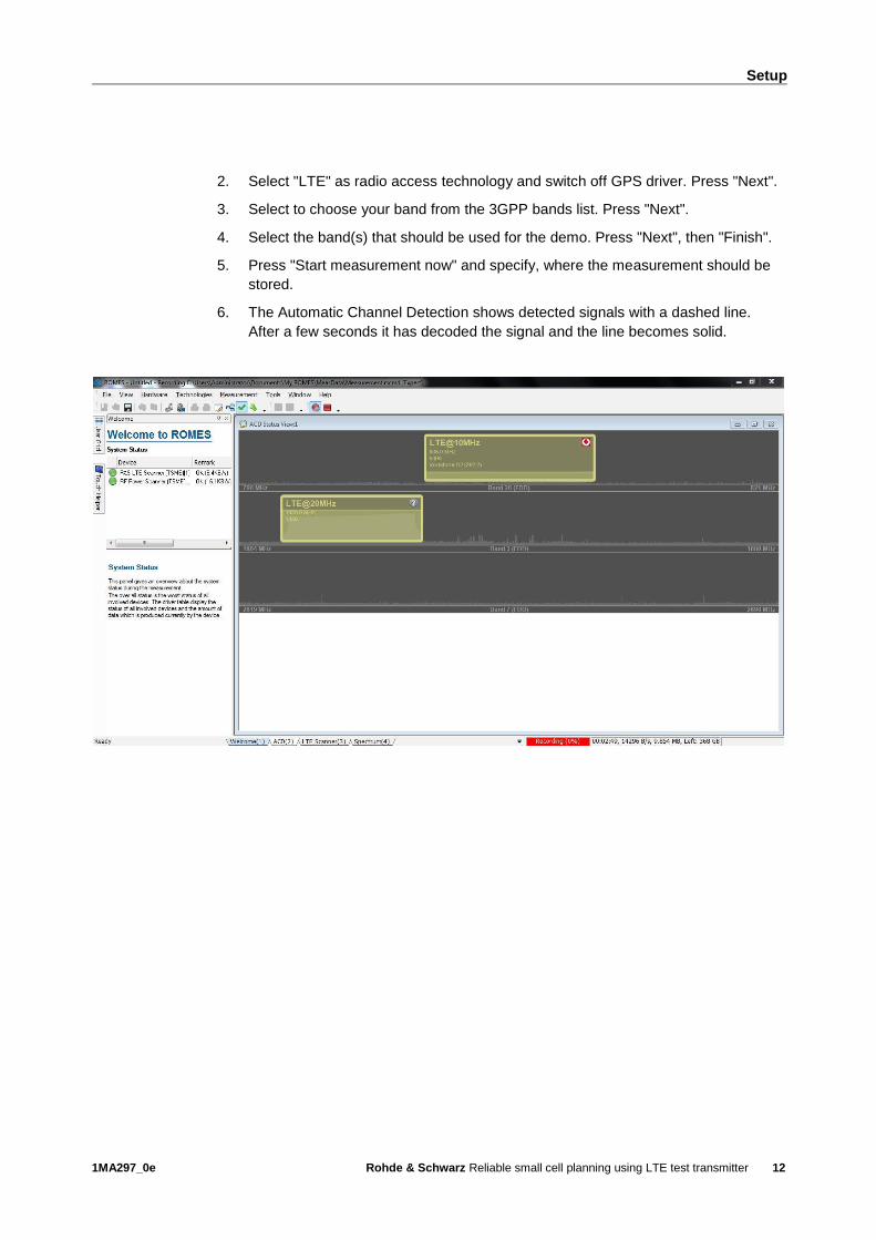
2. Select "LTE" as radio access technology and switch off GPS driver. Press "Next".
3. Select to choose your band from the 3GPP bands list. Press "Next".
4. Select the band(s) that should be used for the demo. Press "Next", then "Finish".
5. Press "Start measurement now" and specify, where the measurement should be
stored.
6. The Automatic Channel Detection shows detected signals with a dashed line.
After a few seconds it has decoded the signal and the line becomes solid.
Analysis of the measurement results
1MA297_0e Rohde & Schwarz Reliable small cell planning using LTE test transmitter
13
4 Analysis of the measurement results
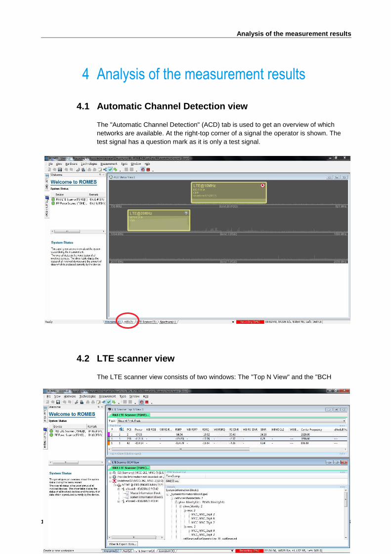
4.1 Automatic Channel Detection view
The "Automatic Channel Detection" (ACD) tab is used to get an overview of which
networks are available. At the right-top corner of a signal the operator is shown. The
test signal has a question mark as it is only a test signal.
4.2 LTE scanner view
The LTE scanner view consists of two windows: The "Top N View" and the "BCH

Analysis of the measurement results
1MA297_0e Rohde & Schwarz Reliable small cell planning using LTE test transmitter
14
View". The windows can be rearranged to suit the personal preferences.
The "Top N View" shows the interesting performance indicators like the RSRP and
SINR. To identify which signal is the test signal use the center frequency. In the
example above the SINR of the test signal is 34.3 dB (1820 MHz center frequency)
compared to 0.3 dB of the networks without indoor installation (adjacent center
frequency 1850 MHz). The SINR improvement by the emulated small cell in this case
is around 34 dB (with only 10 dBm transmit power).
The "BCH View" gives the possibility to have a deeper look into the blocks of the
signals. That's more interesting for analyzing real signals as the transmitted test signal
has only a Master Information Block, but no System Information Block.

Analysis of the measurement results
1MA297_0e Rohde & Schwarz Reliable small cell planning using LTE test transmitter
15
4.3 Spectrum view
The spectrum view consists of three windows. At the top you can choose which band
you want to have a look. In the middle one the spectrum of the chosen band is shown.
At the bottom is a waterfall diagram. This view is good for detecting interferences and
non-continuous signals.

Interpretation of measurement results
1MA297_0e Rohde & Schwarz Reliable small cell planning using LTE test transmitter
16
5 Interpretation of measurement results
For the achievable data throughput at a certain position (or the capacity of a cell as the
sum of all data throughputs of all addressed users) the SINR (Signal to Interference
and Noise Ratio) is crucial. The higher the SINR, the higher is the MCS (Modulation
and Coding Scheme) and consequently the achievable data throughput. The following
graph gives some example information of the MCS vs. SINR relation. This MCS-SINR
relation depends on the specific Base Station vendors' algorithms performance and
scheduler implementation, as well as on the channel fading profile etc.
The measurement example in chapter 4.2 shows an SINR improvement of around 34
dB by the indoor test transmitter (with only 10 dBm transmit power) compared to the
adjacent outdoor signal. With an SINR at the measurement position of 34.3 dB it is
clear that a very high MCS (even in the 256QAM range) could be used and a very high
data throughput can be achieved. So, a small cell in such an environment (with very
low interference and very high SNIR) will offer a huge capacity.
Chapter 2 describes the general procedure for a reliable small cell planning activity.
First we need a record of the actual situation without the planned small cell (SINR-
before). The second step is the measurement with the active test transmitter ideally on
the same operator frequency. This resulting SINR-textTx can be compared with the
SINR-before and the difference is the SINR gain that translates into added throughput
and capacity.
0
100
200
300
400
500
600
700
800
-15 -5 5 15 25 35 45
Re
lative
th
rou
gh
pu
t / %
SINR / dB
Example MCS vs. SINR
64QAM
(MCS 11...19)
256QAM
(MCS 20...27)
16QAM
(MCS 5...10)QPSK (MCS 0...4)
Ordering Information
1MA297_0e Rohde & Schwarz Reliable small cell planning using LTE test transmitter
17
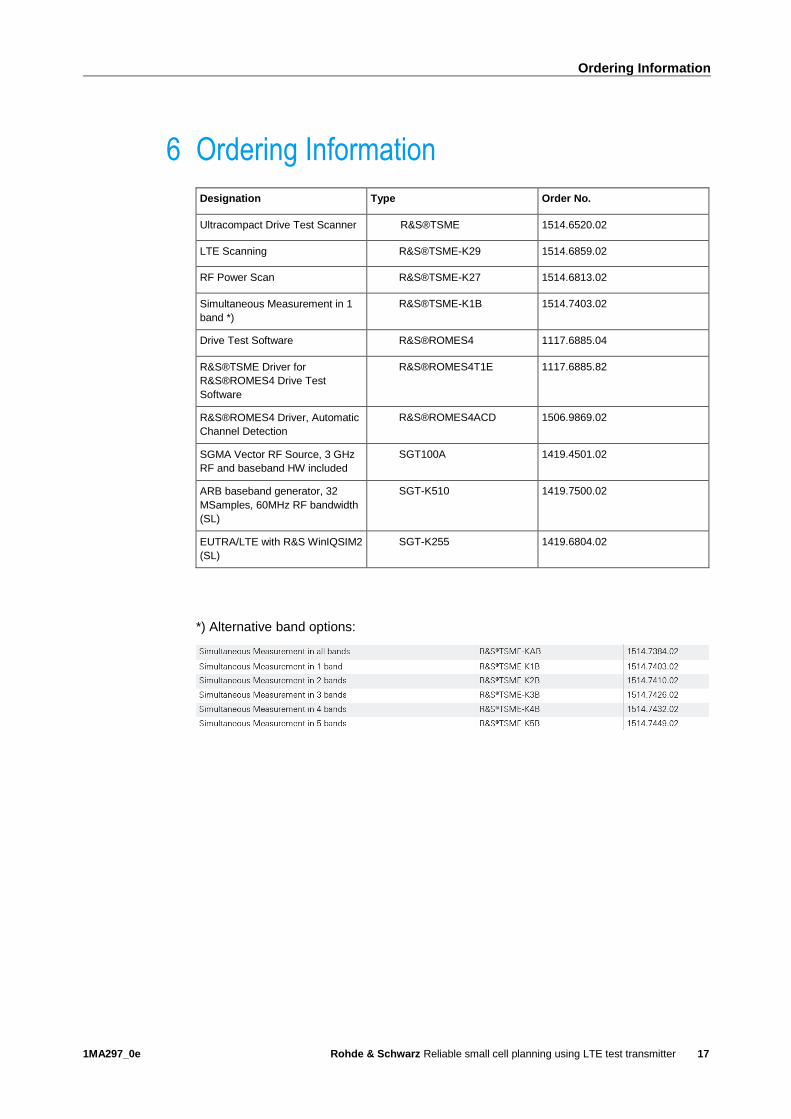
6 Ordering Information
Designation Type Order No.
Ultracompact Drive Test Scanner R&S®TSME 1514.6520.02
LTE Scanning R&S®TSME-K29 1514.6859.02
RF Power Scan R&S®TSME-K27 1514.6813.02
Simultaneous Measurement in 1
band *)
R&S®TSME-K1B 1514.7403.02
Drive Test Software R&S®ROMES4 1117.6885.04
R&S®TSME Driver for
R&S®ROMES4 Drive Test
Software
R&S®ROMES4T1E 1117.6885.82
R&S®ROMES4 Driver, Automatic
Channel Detection
R&S®ROMES4ACD 1506.9869.02
SGMA Vector RF Source, 3 GHz
RF and baseband HW included
SGT100A 1419.4501.02
ARB baseband generator, 32
MSamples, 60MHz RF bandwidth
(SL)
SGT-K510 1419.7500.02
EUTRA/LTE with R&S WinIQSIM2
(SL)
SGT-K255 1419.6804.02
*) Alternative band options:
Rohde & Schwarz
The Rohde & Schwarz electronics group offers
innovative solutions in the following business fields:
test and measurement, broadcast and media, secure
communications, cybersecurity, radiomonitoring and
radiolocation. Founded more than 80 years ago, this
independent company has an extensive sales and
service network and is present in more than 70
countries.
The electronics group is among the world market
leaders in its established business fields. The
company is headquartered in Munich, Germany. It
also has regional headquarters in Singapore and
Columbia, Maryland, USA, to manage its operations
in these regions.
Regional contact
Europe, Africa, Middle East +49 89 4129 12345 [email protected] North America 1 888 TEST RSA (1 888 837 87 72) [email protected] Latin America +1 410 910 79 88 [email protected] Asia Pacific +65 65 13 04 88 [email protected]
China +86 800 810 82 28 |+86 400 650 58 96 [email protected]
Sustainable product design
ı Environmental compatibility and eco-footprint
ı Energy efficiency and low emissions
ı Longevity and optimized total cost of ownership
This application note and the supplied programs
may only be used subject to the conditions of use
set forth in the download area of the Rohde &
Schwarz website.
R&S® is a registered trademark of Rohde & Schwarz GmbH & Co.
KG; Trade names are trademarks of the owners.
Rohde & Schwarz GmbH & Co. KG
Mühldorfstraße 15 | 81671 Munich, Germany
Phone + 49 89 4129 - 0 | Fax + 49 89 4129 – 13777
www.rohde-schwarz.com
PA
D-T
-M:
3573.7
380.0
2/0
2.0
5/E
N/