reliability of freestanding polysilicon microheaters to be ... · pdf filereliability of...
TRANSCRIPT

Rs
DI
A
fsTuapco
K
1
sseracsotelsapc
∗
eliability of freestanding polysilicon microheaters to be used as igniters inolid propellant microthrusters
anick Briand ∗, Phuong Quyen Pham, Nicolaas F. de Rooijnstitute of Microtechnology, University of Neuchatel, Rue Jaquet-Droz 1, P.O. Box 526, CH-2002 Neuchatel, Switzerland
bstract
This paper presents the design, fabrication and characterisation of surface micromachined polysilicon microheaters to be used as microignitersor micropropulsion applications. The microigniters are heated up by Joule effect and the thermal losses through the substrate are minimised byuspending the microheaters above the substrate. The developed process was compatible with the integration of the nozzle part of the microthruster.he electrical, thermal and mechanical characteristics of the microheaters were studied with the aim of evaluating their reliability. Temperaturesp to 470 ◦C could be reached with an electrical power of 45 mW/beam. The current–voltage relation followed a linear characteristic at low power;t high bias voltages, a drift of the electrical resistance was measured after a few I–V cycles at power higher than 40 mW/beam. The elastic and
Published in Sensors and Actuators A: Physical 135, issue 2, 329-336, 2006which should be used for any reference to this work
1
lastic deformation threshold of the microheaters in operation and their maximum deflection before rupture were measured. The microheatersould dissipate relatively high constant powers for a few minutes to hours. The fabricated microheaters are promising candidates for the ignitionf solid propellant microthrusters.
lant; S
s[
mhfielsiboip
eywords: Microheater; Microigniter; Polysilicon; Microthruster; Solid propel
. Introduction
The miniaturisation of huge spacecrafts into micro- or nano-pacecrafts has led to the development of micropropulsionystems. Their integration in microspacecrafts offers consid-rable advantages in terms of downscaling, mass and volumeeduction as well as mission costs lowering. Several solutionsre investigated, such as solid propellant microthrusters [1–4],old-gas microthrusters [5,6], field emission electric propul-ion (FEEP) [7], bi- or mono-propellant microthrusters [8,9]r vaporising liquid microthrusters [10]. By combining MEMSechnology and energetic material science, large quantities ofnergy can be obtained. In this perspective, solid-state propel-ant microthrusters have been developed. Compared to otherolutions, solid propellant microthrusters present the following
dvantages: no liquid fuel leakage due to the use of solid pro-ellant, no moving parts and ignition possible with a low poweronsumption. Their single-shot characteristic can be compen-Corresponding author. Tel.: +41 32 720 5564; fax: +41 32 720 5711.E-mail address: [email protected] (D. Briand).
afppcto
urface micromachining
ated by an array configuration of the micropropulsion system11].
The ignition of the solid propellant is triggered by theicroigniter, which usually consists in a Joule effect micro-
eater. Due to the major role played by the igniter in the deviceunctioning, special attention should be paid to its design and tots characteristics in order to achieve a successful ignition. Jouleffect microheaters as microigniters have been reported in theiterature: polysilicon microheaters thermally insulated from theubstrate by means of a thick dielectric membrane [2], polysil-con heaters on a thin dielectric membrane and fabricated byulk micromachining [11,15], platinum/titanium microheatersn a diaphragm [3] or nickel chromium aluminum copper wirenserted in a slot of the microthruster [4]. All these methodsresent some drawbacks. In [2], the power consumption is rel-tively high to an insufficient thermal insulation of the igniterrom the substrate. In the case of igniters on membranes, low-ower is ensure but filling of the igniter with propellant becomes
roblematic, ignition success rate is an issue and debris arereate due to the breaking of the membrane during the combus-ion [3,11]. Despite that polysilicon exhibits a long term driftf its electrical resistance at relatively high temperatures [21],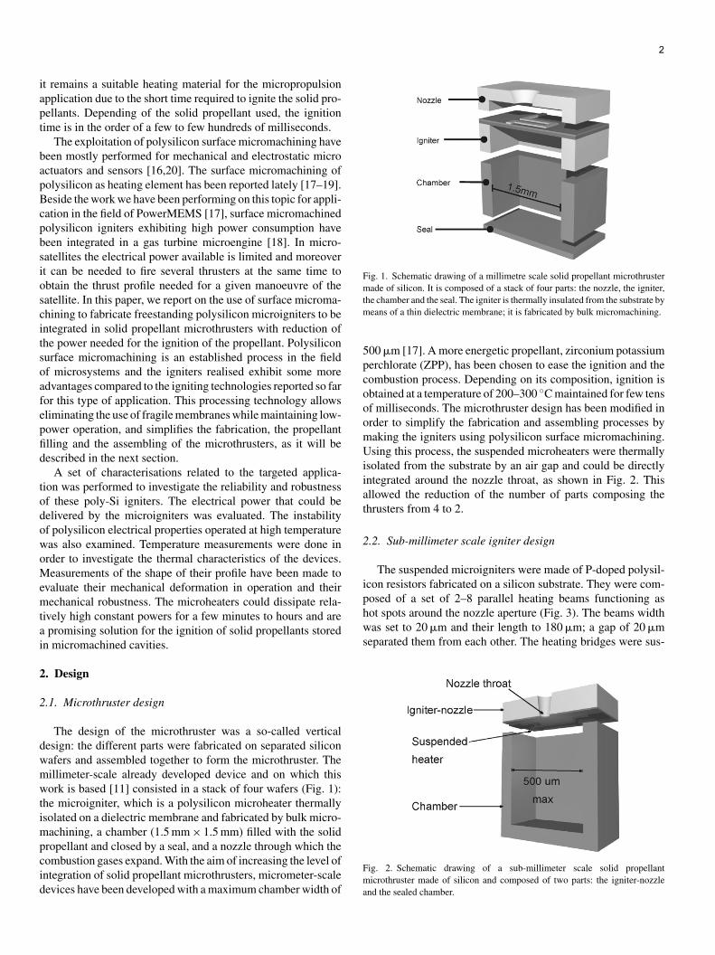
iapt
bapBcpbsioscitsoafepfid
todowoMemtai
2
2
dwmwtimpcid
Fig. 1. Schematic drawing of a millimetre scale solid propellant microthrustermade of silicon. It is composed of a stack of four parts: the nozzle, the igniter,tm
5pcooomUiiat
2
iphot spots around the nozzle aperture (Fig. 3). The beams widthwas set to 20 �m and their length to 180 �m; a gap of 20 �mseparated them from each other. The heating bridges were sus-
2
t remains a suitable heating material for the micropropulsionpplication due to the short time required to ignite the solid pro-ellants. Depending of the solid propellant used, the ignitionime is in the order of a few to few hundreds of milliseconds.
The exploitation of polysilicon surface micromachining haveeen mostly performed for mechanical and electrostatic microctuators and sensors [16,20]. The surface micromachining ofolysilicon as heating element has been reported lately [17–19].eside the work we have been performing on this topic for appli-ation in the field of PowerMEMS [17], surface micromachinedolysilicon igniters exhibiting high power consumption haveeen integrated in a gas turbine microengine [18]. In micro-atellites the electrical power available is limited and moreovert can be needed to fire several thrusters at the same time tobtain the thrust profile needed for a given manoeuvre of theatellite. In this paper, we report on the use of surface microma-hining to fabricate freestanding polysilicon microigniters to bentegrated in solid propellant microthrusters with reduction ofhe power needed for the ignition of the propellant. Polysiliconurface micromachining is an established process in the fieldf microsystems and the igniters realised exhibit some moredvantages compared to the igniting technologies reported so faror this type of application. This processing technology allowsliminating the use of fragile membranes while maintaining low-ower operation, and simplifies the fabrication, the propellantlling and the assembling of the microthrusters, as it will beescribed in the next section.
A set of characterisations related to the targeted applica-ion was performed to investigate the reliability and robustnessf these poly-Si igniters. The electrical power that could beelivered by the microigniters was evaluated. The instabilityf polysilicon electrical properties operated at high temperatureas also examined. Temperature measurements were done inrder to investigate the thermal characteristics of the devices.easurements of the shape of their profile have been made to
valuate their mechanical deformation in operation and theirechanical robustness. The microheaters could dissipate rela-
ively high constant powers for a few minutes to hours and arepromising solution for the ignition of solid propellants stored
n micromachined cavities.
. Design
.1. Microthruster design
The design of the microthruster was a so-called verticalesign: the different parts were fabricated on separated siliconafers and assembled together to form the microthruster. Theillimeter-scale already developed device and on which thisork is based [11] consisted in a stack of four wafers (Fig. 1):
he microigniter, which is a polysilicon microheater thermallysolated on a dielectric membrane and fabricated by bulk micro-
achining, a chamber (1.5 mm × 1.5 mm) filled with the solid
ropellant and closed by a seal, and a nozzle through which theombustion gases expand. With the aim of increasing the level ofntegration of solid propellant microthrusters, micrometer-scaleevices have been developed with a maximum chamber width ofFma
he chamber and the seal. The igniter is thermally insulated from the substrate byeans of a thin dielectric membrane; it is fabricated by bulk micromachining.
00 �m [17]. A more energetic propellant, zirconium potassiumerchlorate (ZPP), has been chosen to ease the ignition and theombustion process. Depending on its composition, ignition isbtained at a temperature of 200–300 ◦C maintained for few tensf milliseconds. The microthruster design has been modified inrder to simplify the fabrication and assembling processes byaking the igniters using polysilicon surface micromachining.sing this process, the suspended microheaters were thermally
solated from the substrate by an air gap and could be directlyntegrated around the nozzle throat, as shown in Fig. 2. Thisllowed the reduction of the number of parts composing thehrusters from 4 to 2.
.2. Sub-millimeter scale igniter design
The suspended microigniters were made of P-doped polysil-con resistors fabricated on a silicon substrate. They were com-osed of a set of 2–8 parallel heating beams functioning as
ig. 2. Schematic drawing of a sub-millimeter scale solid propellanticrothruster made of silicon and composed of two parts: the igniter-nozzle
nd the sealed chamber.

Fig. 3. Schematic drawing of a micrometer-scale microigniter with an integratedntt
ptoe
itoc5
3
pFm
gen atmosphere to form ohmic contacts with the polysilicon.In order to integrate the nozzle during the igniter fabrication,
a few additional process steps can be performed. First the ther-mally grown passivating silicon dioxide would be opened by
ozzle on a silicon substrate. The polysilicon microheaters are suspended abovehe passivated substrate and anchored to the substrate at their extremities, wherehey are electrically connected with aluminum lines.
ended above the passivated substrate. The design as well ashe fabrication process of the igniters allowed the integrationf a divergent nozzle through which the combustion gas can bevacuated.
In order to demonstrate the concept of freestanding polysil-con microigniters, the fabricated structures were designedo fit in a 1.0 mm × 1.0 mm chamber. An appropriate layoutf the microheaters would allow their integration in smallerhambers: one pair of parallel bridges could be arranged in00 �m × 500 �m chambers.
. Fabrication
The igniters were fabricated on 525 �m thick silicon wafers,olished on the topside. The fabrication process is illustrated inig. 4. It started with the passivation of the substrate by a ther-ally grown silicon dioxide and a LPCVD silicon nitride. The
Fig. 4. Fabrication process of the microigniter (cross-section): (a) oxidationand Si3N4 deposition; (b) sacrificial APCVD SiO2 deposition and patterning;(c) Si3N4 and poly-Si deposition, doping and patterning (in dashed lines: nozzleetching if also integrated); (d) sacrificial layer etching; (e) aluminum contactsdeposition.
Fi
sacrificial layer consisting in a 1.2 �m thick layer of APCVDsilicon oxide was then deposited, densified at 625 ◦C for 15 minunder a nitrogen atmosphere and patterned. On top of it wasdeposited a double layer of 200 nm of low stress LPCVD siliconnitride and 700 nm of LPCVD polysilicon. The silicon nitridehad a residual tensile stress whereas the polysilicon had a com-pressive stress. The deposition of polysilicon was performed at600 ◦C and its doping was achieved by the diffusion of phospho-rous from a layer of doped APCVD silicon dioxide. The nextstep consisted in patterning the double layer of silicon nitride andpolysilicon by reactive ion etching (RIE) to form the electricalresistors. The release of the polysilicon resistors was performedby wet etching the sacrificial APCVD silicon dioxide layer ina solution of 50% hydrofluoric acid. Then the aluminum inter-connections were evaporated through a shadow mask in order toprevent the stiction of the microheaters to the substrate. Finally,the aluminum was annealed at 450 ◦C for 30 min under a nitro-
3
ig. 5. Pictures of different designs of polysilicon surface micromachinedgniters composed of (a) 2 × 2 suspended beams and (b) 2 × 4 suspended beams.
Bwraopstoibo
4
bacst
m
Fttp
F2
Up
4
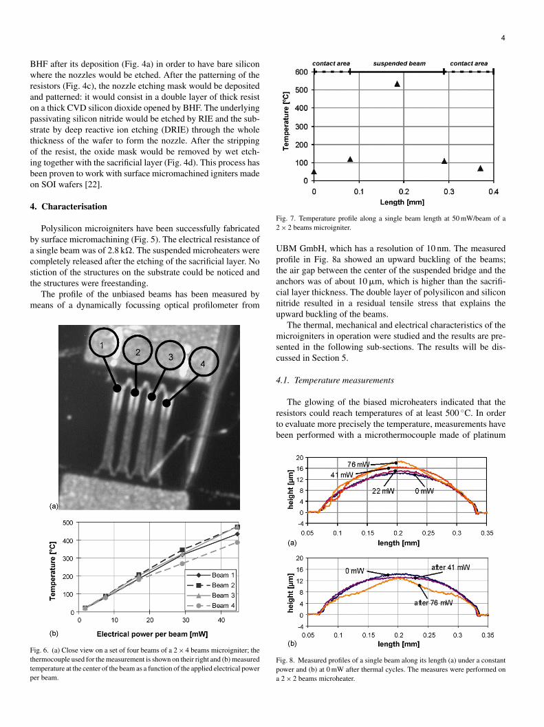
HF after its deposition (Fig. 4a) in order to have bare siliconhere the nozzles would be etched. After the patterning of the
esistors (Fig. 4c), the nozzle etching mask would be depositednd patterned: it would consist in a double layer of thick resistn a thick CVD silicon dioxide opened by BHF. The underlyingassivating silicon nitride would be etched by RIE and the sub-trate by deep reactive ion etching (DRIE) through the wholehickness of the wafer to form the nozzle. After the strippingf the resist, the oxide mask would be removed by wet etch-ng together with the sacrificial layer (Fig. 4d). This process haseen proven to work with surface micromachined igniters maden SOI wafers [22].
. Characterisation
Polysilicon microigniters have been successfully fabricatedy surface micromachining (Fig. 5). The electrical resistance ofsingle beam was of 2.8 k�. The suspended microheaters wereompletely released after the etching of the sacrificial layer. No
tiction of the structures on the substrate could be noticed andhe structures were freestanding.The profile of the unbiased beams has been measured byeans of a dynamically focussing optical profilometer from
ig. 6. (a) Close view on a set of four beams of a 2 × 4 beams microigniter; thehermocouple used for the measurement is shown on their right and (b) measuredemperature at the center of the beam as a function of the applied electrical powerer beam.
tacnu
msc
4
rtb
Fpa
ig. 7. Temperature profile along a single beam length at 50 mW/beam of a× 2 beams microigniter.
BM GmbH, which has a resolution of 10 nm. The measuredrofile in Fig. 8a showed an upward buckling of the beams;he air gap between the center of the suspended bridge and thenchors was of about 10 �m, which is higher than the sacrifi-ial layer thickness. The double layer of polysilicon and siliconitride resulted in a residual tensile stress that explains thepward buckling of the beams.
The thermal, mechanical and electrical characteristics of theicroigniters in operation were studied and the results are pre-
ented in the following sub-sections. The results will be dis-ussed in Section 5.
.1. Temperature measurements
The glowing of the biased microheaters indicated that theesistors could reach temperatures of at least 500 ◦C. In ordero evaluate more precisely the temperature, measurements haveeen performed with a microthermocouple made of platinum
ig. 8. Measured profiles of a single beam along its length (a) under a constantower and (b) at 0 mW after thermal cycles. The measures were performed on2 × 2 beams microheater.

Fig. 9. I–V characteristic of a single beam: the relation is linear until about20 mW/beam; at higher power, the resistance decreases.
Fv
amSm
sttoidmtm
otaialao5
4
aptotp
Ft
ig. 10. Electrical power per beam vs. bias voltage: the decrease of the resistancealue after several I–V cycles results in an electrical power drift.
nd platinum/rhodium wires of 1.3 �m of diameter (S-type ther-ocouple). The measurements were performed at the FEMTO-T laboratory, in the laboratory room environment with aonitoring of the ambient temperature. This laboratory has a
eatc
ig. 11. Pictures showing the rupture of a set of three beams, with a slow voltage swe
0 at 0 V; (b) buckling of the middle beam; (c) rupture of the middle beam; (d) ruptur
trong know-how in the fabrication and the use of such micro-hermocouples [23]. The thermocouple was put in contact withhe beams using an X–Y–Z micromanipulating table under anptical microscope. Precision on the temperature measurementss normally estimated to be 2% over the whole temperature rangeue mainly to the thermal contact resistance. Fig. 6b shows theeasured temperatures as a function of the applied power on
he center of each of the four beams indicated on Fig. 6a. Theeasured structure was a 2 × 4 beams microigniter.Temperatures up to 470 ◦C could be reached with a power
f 45 mW/beam. The measured temperatures were higher onhe inner beams than on the outer ones with a difference ofbout 50–100 ◦C. This was identified to be due to the mutualnfluence of the parallel beams. The temperature profile alongsingle beam at 50 mW/beam (Fig. 7) shows that the thermal
osses through the contacts were very low: the contacts stayedt a temperature close to room temperature whereas the centerf the suspended beams could reach temperatures higher than00 ◦C.
.2. Mechanical deformation
The deformation profile along the beam length was measuredt room temperature—0 mW—and when operating at constantower in laboratory environment, ramping up the power eachime from 0 mW to be able to look at when plastic deformationccurs (Fig. 8a). Power was kept up for few tens of secondshe time to acquire the profile of the beam using the opticalrofilometer.
The Joule heating effect of the electrical beams induced by the
5
lectrical current triggers the thermal expansion of the structuresnd causes their mechanical buckling [24]. The elastic deforma-ion threshold has been measured around 25 mW/beam, whichorresponded to a temperature of about 250 ◦C. As more power
ep starting at 0 V and increasing with a step of 100 mV every 500 ms: (a) timee of the outer beams.
wtd47
4
ii2ai
tdaaaaatbcdm
4
iit8c
itditbttaaa
4
mpwrw
Fca
6
as dissipated, the temperature increased, leading to a higherhermal expansion and deformation of the beams. The plasticeformation threshold of the microheaters occurred at about0 mW/beam (Fig. 8b). A deflection of 4.5 �m was measured at6 mW/beam.
.3. Electrical properties
The electrical properties of the microigniters were also stud-ed. The current to voltage characteristic of a single beams shown on Fig. 9. The I–V relation was linear until about0 mW/beam. A decrease of the electrical resistance was noticedfter 35 mW/beam, resulting in a significant increase of thenjected current.
The decrease of the resistance could be caused by the recrys-allisation of polysilicon at high temperatures, as it has beenescribed in the literature [21,25]. A drift of the electrical powerfter a few cycles above 40 mW/beam was observed (Fig. 10);ccording to the temperature versus power graph of Fig. 6bnd to the temperature profile measurement (Fig. 7), temper-tures higher than 450 ◦C were reached by the suspended beamst that power and could lead to the polysilicon recrystallisa-ion, thus to a change of the electrical resistance. Nonetheless,ecause of the required short ignition time and the one-shotharacteristic of the application, it is assumed that the powerrift of polysilicon does not prevent a good functioning of theicroigniters.
.4. Robustness
The rupture of the microigniters was studied in order tonvestigate their robustness. The experiments consisted in apply-ng a relatively high constant power during a few minuteso a few hours. The microheaters could deliver powers up to0 mW/beam for a few minutes; a lower power of 60 mW/beamould be applied for hours without beam rupture.
As a result of the short time required to ignite the propellant,t was also important to examine the short term robustness ofhe microheaters. Fig. 11 shows a series of video frames takenuring the rupture of the microigniter bridges under an increas-ng voltage sweep starting at 0 V until its breakage. One can seehat the resistive heating of the microheaters caused their self-uckling. As the power and temperature were further increased,he beams broke off: the inner beam broke first, probably due tohe fact that it reached higher temperatures than the outer ones,s explained previously. For a fast voltage sweep, i.e. with a volt-ge increment of 100 mV every 50 ms, beams rupture occurredt a power higher than 80 mW/beam.
.5. Ignition tests
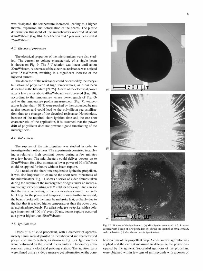
Drops of ZPP solid propellant, with a diameter of approxi-ately 1 mm, were deposited on the fabricated and characterised
olysilicon micro-heaters, as shown in Fig. 12a. Ignition testsere performed on the coated microigniters in laboratory envi-
onment using a electrical probing station. The ignition testsere filmed using a video camera to get information on the com-
basw
ig. 12. Pictures of the ignition test: (a) Microigniter composed of 2x4 beamsovered with a drop of ZPP propellant (b) during the ignition at 80 mW/beamnd combustion (c) after the successful ignition test.
ustion time of the propellant drop. A constant voltage pulse was
pplied and the current measured to determine the power dis-ipated by the igniters. Successful ignitions of the propellantere obtained within few tens of milliseconds with a power of
8d
5
csiflstlotepis
htcwhoTi1gwiieb
dnfaa
6
aassrcwablc
om
A
spUooGSFtUttfmd
R
[
[
0 mW/beam. From the video of the ignition test, it has beeneduced that the combustion time was smaller than 120 ms.
. Discussion
The mechanical characterisation of the microigniters indi-ated that the air gap between the polysilicon and the sub-trate was much higher than the sacrificial layer thickness andncreased with the temperature. The micro-heaters were there-ore perfectly released with no stiction and the large air gapimited the heat losses through the substrate. The filling of thetructures with the solid propellant might cause the rupture ofhe suspended beams because of their buckling; however, it isikely that the propellant would deform the flexible beams with-ut breaking them. Indeed the large air gap could help to avoidhe sticking of the polysilicon beams on the substrate when cov-red with propellant. The ignition tests performed on drops ofropellant showed that these polysilicon heaters could operaten a reliable manner and deliver the required power to achieve auccessful ignition.
The temperature measurements showed that temperaturesigher than the 200–300 ◦C for few tens of milliseconds requiredo ignite the ZPP propellant could be reached by the fabri-ated microheaters. Indeed glowing of the polysilicon beamsas obtained. The power applied during the ignition tests wasigher than the expected ignition power, 80 mW/beam insteadf 20–30 mW/beam measured to reach the required 200–300 ◦C.his can be explained by the additional thermal mass for the
gniters coated with propellant. Nevertheless, with drops ofmm in diameter, the volume of the drops of propellant was big-er than the volume that would be needed to fill up the 500 �mide chambers of the sub-millimetre scale thrusters presented
n Section 2.2. These igniters would be therefore suitable for thegnition of ZPP stored in sub-millimiter scale chambers, consid-ring that for few tens of millisecond even higher power coulde deliver by the polysilicon micro-heaters.
The experiments showed that despite the electrical powerrift of polysilicon at high temperature, due the small timeeeded for the ignition of solid propellant, the microignitersulfil the ignition requirements for ZPP in terms of temperaturend energy as well as the electrical specifications needed for thepplication.
. Conclusion
This communication described the fabrication and the char-cterisation of freestanding polysilicon micro-heaters to be useds microigniters for solid propellant microthrusters. The reali-ation of polysilicon microheaters was successfully achieved byurface micromachining. Temperatures up to 470 ◦C could beeached with an electrical power of 45 mW/beam. The beamsould withstand up to 80 mW for a few seconds before rupture;ith a maximum relative deflection of 4.5 �m. Thermal cycles
t high temperatures resulted in the plastic deformation of theeams as well as in a change of their electrical resistance, whiched to a drift in the power characteristic. These surface microma-hined polysilicon micro-heaters are promising for the ignition
[
f solid propellant. Further work would consist in testing theseicroigniters in a fully assembled micrometer-scale thruster.
cknowledgments
This work has been supported by the European Commis-ion (5th framework IST-99047). The partners involved in theroject were the Angstom Space Technology Centre (ASTC),niversity of Uppsala, Sweden, the Institute of Microtechnol-gy (IMT), University of Neuchatel, Switzerland, the Institutef Microsystem Technology (IMTEK), University of Freiburg,ermany, the Laboratory for Analysis and Architecture ofystems (LAAS), Centre National de Recherche Scientifique,rance, Etienne LACROIX Tous Artifices S.A., France, and
he Instrumentation and Communications Systems group (SIC),niversity of Barcelona, Spain. The authors would like to thank
he IMT-Comlab technical staff for their support in the fabrica-ion of the devices. We are also grateful to Dr. Laurent Thieryrom the FEMTO-ST (CREST), Belfort, France, for the ther-ocouple measurements and to LACROIX for the propellant
eposition.
eferences
[1] C. Rossi, S. Orieux, B. Larangot, T.D. Conto, D. Esteve, Design, fabricationand modeling of solid propellant microrocket—application to micropropul-sion, Sens. Actuators A 99 (2002) 129–133.
[2] D.H. Lewis Jr., S.W. Janson, R.B. Cohen, E.K. Antonsson, Digital micro-propulsion, Sens. Actuators A 80 (2000) 143–154.
[3] S. Tanaka, R. Hosokawa, S. Tokudome, K. Hori, H. Saito, M. Watanabe, M.Esashi, MEMS-based solid propellant rocket array thruster with electricalfeedthroughs, Trans. J. Jpn. Soc. Aeronaut. Space Sci. 46 (151) (2003)47–51.
[4] K.L. Zhang, S.K. Chou, S.S. Ang, Development of a solid propellantmicrothruster with chamber and nozzle etched on a wafer surface, J.Micromech. Microeng. 14 (2004) 785–792.
[5] J. Mueller, Thruster options for microspacecraft—a review andevaluation of existing hardware and emerging technologies, in:AIAA/ASME/SAE/ASEE Joint Propulsion Conference and Exhibit, Seat-tle, Washington, USA, July 6–9, 1997.
[6] J. Kohler, J. Bejhed, H. Kratz, F. Bruhn, U. Lindberg, K. Hjort, L. Stenmark,A hybrid cold gas microthruster system for spacecraft, Sens. Actuators A97–98 (2002) 587–598.
[7] J. Mitterauer, Micropropulsion for small spacecraft: a new challenge forFEEP (field effect electric propulsion) and MILMILS (microstructures liq-uid metal ion sources), in: NanoTech 2002—At the Edge of Revolution,Houston, Texas, USA, September 9–12, 2002.
[8] A.P. London, A.A. Ayon, A.H. Epstein, S.M. Spearing, T. Harrison, Y.Peles, J.L. Kerrebrock, Microfabrication of a high pressure bipropellantrocket engine, Sens. Actuators A 92 (2001) 1–7.
[9] D. Platt, A monopropellant milli-Newton thruster system for attitude con-trol of nanosatellites, in: 16th Annual AIAA/USU Conference on SmallSatellites, Logan, Utah, USA, August 12–15, 2002.
10] E.V. Mukerjee, A.P. Wallace, K.Y. Yan, D.W. Howard, R.L. Smith, S.D.Collins, Vaporizing liquid microthruster, Sens. Actuators A 83 (2000)231–236.
11] B. Larangot, C. Rossi, T. Camps, A. Berthold, P.Q. Pham, D. Briand, N.F. deRooij, M. Puig-Vidal, P. Miribel, E. Montane, E. Lopez, J. Samitier, Solidpropellant micro-rockets—towards a new type of power MEMS, in: Nan-
7
oTech 2002—At the Edge of Revolution, Houston, Texas, USA, September9–12, 2002.
15] C. Rossi, D. Esteve, P. Temple-Boyer, G. Delannoy, Realization, char-acterization of micro pyrotechnic actuators and FEM modelling of thecombustion ignition, Sens. Actuators A 70 (1998) 141–147.

[
[
[
[
[
[
[
[
[
[
B
DfMrf2ieia
NnahSa
16] M.-A. Gretillat, F. Gretillat, N.F. de Rooij, Micromechanical relay withelectrostatic actuation and metallic contacts, J. Micromech. Microeng. 9(1999) 324–331.
17] P.Q. Pham, D. Briand, C. Rossi, N.F. de Rooij, Downscaling of solidpropellant pyrotechnical microsystems, in: Transducers ’03, The 12th Inter-national Conference on Solid State Sensors, Actuators and Microsystems,Boston, Massachusetts, USA, June 8–12, 2003.
18] X. Zhang, A. Mehra, A.A. Ayon, I.A. Waitz, Igniters and temperature sen-sors for a micro-scale combustion system, Sens. Actuators A 103 (2003)253–262.
19] E.S. Kolesar, W.E. Odom, J.A. Jayachandran, M.D. Ru, S.Y. Ko, J.T.Howard, P.B. Allen, J.M. Wilken, N.C. Boydston, J.E. Bosch, R.J. Wilks,J.B. McAllister, Design and performance of an electrothermal MEMSmicroengine capable of bi-directional motion, Thin Solid Films 447–448(2004) 481–488.
20] M. Dumitrescu, C. Cobianu, D. Lungu, D. Dascalu, A. Pascu, S. Kolev,A. van den Berg, Thermal simulation of surface micromachined polysil-icon hot plates of low power consumption, Sens. Actuators A 76 (1999)51–56.
21] M. Ehmann, P. Ruther, M. von Arx, O. Paul, Operation and short-term driftof polysilicon-heated CMOS microstructures at temperature up to 1200 K,J. Micromech. Microeng. 11 (2001) 397–401.
22] P.Q. Pham, D. Domine, D. Briand, N.F. de Rooij, Development of micro-heaters on SOI for microignition applications, in: 15th Micromechan-ics Europe Workshop (MME), Leuven, Belgium, September, 2004, pp.309–312.
23] L. Thiery, D. Briand, A. Odaymat, N.F. de Rooij, Contribution of scan-ning probe temperature measurements to the thermal analysis of micro-hotplates, in: International Workshops on Thermal Investigations of ICsand Systems, Therminic 2004, Sophia Antipolis, France, September, 2004,pp. 23–28.
ath(m
24] M. Chiao, L. Lin, Self-buckling of micromachined beams under resistiveheating, J. Microelectromech. Syst. 9 (1) (2000) 146–151.
25] O. Grudin, R. Marinescu, L. Landsberger, D. Cheeke, M. Kahrizi,Microstructure release and test techniques for high-temperature micro hot-plate, in: Proceedings of the IEEE Canadian Conference on Electrical andComputer Engineering, vol. 3, no. 9, May 12, 1999, pp. 1610–1615.
iographies
anick Briand received his BE degree and MASc degree in Engineering Physicsrom Ecole Polytechnique in Montreal, in collaboration with the Laboratoire des
ateriaux et du Genie Physique (INPG) in Grenoble, France in 1995 and 1997,espectively. He obtained his PhD degree in the field of micro-chemical systemsrom the Institute of Microtechnology, University of Neuchatel, Switzerland in001, where he is currently a project leader. He is in charge of European andndustrial projects and of the supervision of doctoral students. His research inter-sts in the field of microsystems include PowerMEMS, polymeric MEMS, thentegration of nanostructures on microsystems, and the development of micro-nalytical instruments for gas-sensing applications.
icolaas F. de Rooij received his PhD degree from Twente University of Tech-ology, The Netherlands in 1978. From 1978 to 1982, he worked at the Researchnd Development Department of Cordis Europa N.V., The Netherlands. In 1982,e joined the Institute of Microtechnology of the University of Neuchatel,witzerland (IMT UNI-NE), as Professor and head of the Sensors, Actuatorsnd Microsystems Laboratory. Since October 1990 till October 1996, he was
8
cting as Director of the IMT UNI-NE. Since 1987, he has been a Lecturer athe Swiss Federal Institute of Technology, Zurich (ETHZ), and since 1989, heas also been a Professor at the Swiss Federal Institute of Technology, LausanneEPFL). His research activities include microfabricated sensors, actuators andicrosystems.