release notes mt48436 infiniscale iv firmwareie s lo g · pdf filethese are the release notes...
TRANSCRIPT

Mellanox Technologies
Release Notes
Mellan
ox Tech
nologie
sMT48436 InfiniScale® IV Firmware
fw-IS4 Rev 7.2.400

Rev 7.2.400 Mellanox Technologies
2
Mellan
ox Tech
nologie
s
© Copyright 2009. Mellanox Technologies, Inc. All Rights Reserved.
Mellanox Technologies, Inc. 350 Oakmead Parkway, Suite 100 Sunnyvale, CA 94085 U.S.A. www.mellanox.com
Tel: (408) 970-3400 Fax: (408) 970-3403
Mellanox Technologies Ltd PO Box 586 Hermon Building Yokneam 20692 Israel
Tel: +972-4-909-7200 Fax: +972-4-959-3245
NOTE:
THIS INFORMATION IS PROVIDED BY MELLANOX FOR INFORMATIONAL PURPOSES ONLY AND ANY EXPRESS OR IMPLIED WARRANTIES, INCLUDING, BUT NOT LIMITED TO, THE IMPLIED WAR-RANTIES OF MERCHANTABILITY AND FITNESS FOR A PARTICULAR PURPOSE ARE DISCLAIMED. IN NO EVENT SHALL MELLANOX BE LIABLE FOR ANY DIRECT, INDIRECT, INCIDENTAL, SPECIAL, EXEMPLARY, OR CONSEQUENTIAL DAMAGES (INCLUDING, BUT NOT LIMITED TO, PROCUREMENT OF SUBSTITUTE GOODS OR SERVICES; LOSS OF USE, DATA, OR PROFITS; OR BUSINESS INTERRUP-TION) HOWEVER CAUSED AND ON ANY THEORY OF LIABILITY, WHETHER IN CONTRACT, STRICT LIABILITY, OR TORT (INCLUDING NEGLIGENCE OR OTHERWISE) ARISING IN ANY WAY OUT OF THE USE OF THIS HARDWARE, EVEN IF ADVISED OF THE POSSIBILITY OF SUCH DAMAGE.
InfiniScale IV fw-48436 Firmware Release Notes
Mellanox Technologies Rev 7.2.400
3
Mellan
ox Tech
nologie
s
1 Overview
These are the release notes for the MT48436 InfiniScale® IV firmware fw-IS4, Rev 7.2.400. This firmware comple-ments the InfiniScale IV MT48436 silicon architecture with a set of advanced features, allowing easy and remote management of the switch.
Note: After burning new firmware to the InfiniScale IV switch device, reboot the switch so that the new firmware can take effect.
This document includes the following sections:
• “Overview” (page 3)- “Notes on This Release” (page 3)- “Requirements” (page 3)
• “Changes and Major New Features” (page 3)• “Unsupported Features” (page 3)• “Bug Fixes” (page 4)• “Known Issues” (page 4)• “SMA/GSA Attributes” (page 5)• “Firmware Initialization And Configuration (.INI) File” (page 8)• “History of Bug Fixes” (page 20)
1.1 Notes on This Release- This firmware release complies with the InfiniScale IV MT48436 Programmer’s Reference Manual (PRM),
Doc. #2885, Rev 0.23 or later.
1.2 Requirements• One of the following burning tools:
- flint or mlxburn applications (part of MFT ver. 2.5.0 or later)• Burning firmware to the switch can be performed In-Band or via the I2C-compatible interface. Burning via the
I2C-compatible interface requires one of the following I2C cards:- MTUSB-1 (USB to I2C adapter)- ISA Calibre
2 Changes and Major New Features
• Mellanox auto-negotiation:- Enhanced the sweep procedure to yield better eye measurements- Added an optional crosstalk reduction algorithm. Enabling this algorithm multiplies the auto-negotiation
duration by 4.• Command interface:
- Updated the SET_PORT command to allow for changing the node description
3 Unsupported Features
• Baseboard Management Agent (BMA)

Bug Fixes
Rev 7.2.400 Mellanox Technologies
4
Mellan
ox Tech
nologie
s
4 Bug Fixes
None in this release.
5 Known Issues
Table 1 - Known Issues
Index Issue Description
Current Implemented
Workaround in FW
Possible Workaround
Scheduled Release (fix)
1. AUTOCONF_1X4X8X12X setting is not supported
AUTOCONF_1X4X8X12X setting for the [LINK_WIDTH] parameter width_supported_clusterX is not supported
NA NA A future firm-ware release
2. Mellanox auto-negotiation does not support 12X links
NA NA NA
3. LinkWidth in INI file cannot be specified using IB port numbers
LinkWidth INI settings must use HW port numbers
NA NA A future firm-ware release
4. No M_Key check is performed for packets sent by the external SMA
NA NA Next release
5. If IB Port 1 is configured as 1x SDR, the link may be unstable
NA NA Next release
6. Temperature Sensing a. TRAP is not implemented. b. If the over-temperature warning GPIO mode is set (wgm=1), the GPIO cannot be cleared by MAD
NA NA Next release
InfiniScale IV fw-48436 Firmware Release Notes
Mellanox Technologies Rev 7.2.400
5
Mellan
ox Tech
nologie
s
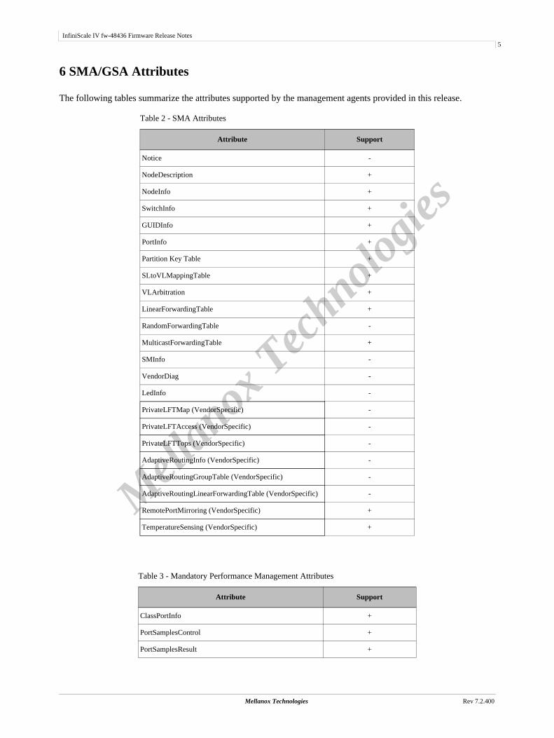
6 SMA/GSA Attributes
The following tables summarize the attributes supported by the management agents provided in this release.
Table 2 - SMA Attributes
Attribute Support
Notice -
NodeDescription +
NodeInfo +
SwitchInfo +
GUIDInfo +
PortInfo +
Partition Key Table +
SLtoVLMappingTable +
VLArbitration +
LinearForwardingTable +
RandomForwardingTable -
MulticastForwardingTable +
SMInfo -
VendorDiag -
LedInfo -
PrivateLFTMap (VendorSpecific) -
PrivateLFTAccess (VendorSpecific) -
PrivateLFTTops (VendorSpecific) -
AdaptiveRoutingInfo (VendorSpecific) -
AdaptiveRoutingGroupTable (VendorSpecific) -
AdaptiveRoutingLinearForwardingTable (VendorSpecific) -
RemotePortMirroring (VendorSpecific) +
TemperatureSensing (VendorSpecific) +
Table 3 - Mandatory Performance Management Attributes
Attribute Support
ClassPortInfo +
PortSamplesControl +
PortSamplesResult +
SMA/GSA Attributes
Rev 7.2.400 Mellanox Technologies
6
Mellan
ox Tech
nologie
s
PortCounters +
PortCountersExtended (for data counters only) +
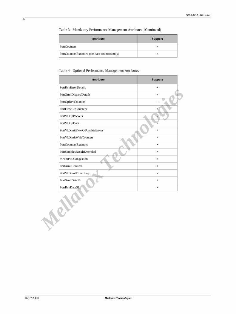
Table 4 - Optional Performance Management Attributes
Attribute Support
PortRcvErrorDetails +
PortXmitDiscardDetails +
PortOpRcvCounters -
PortFlowCtlCounters +
PortVLOpPackets -
PortVLOpData -
PortVLXmitFlowCtlUpdateErrors +
PortVLXmitWaitCounters +
PortCountersExtended +
PortSamplesResultExtended +
SwPortVLCongestion +
PortXmitConCtrl +
PortVLXmitTimeCong -
PortXmitDataSL +
PortRcvDataSL +
Table 3 - Mandatory Performance Management Attributes (Continued)
Attribute Support

InfiniScale IV fw-48436 Firmware Release Notes
Mellanox Technologies Rev 7.2.400
7
Mellan
ox Tech
nologie
s
Table 5 - VendorSpecific MADs
InfiniBand Management Class Management Attribute Supported by Last Release
Supported by New Release
0x0AVendorSpecific class
0x0001 ClassPortInfo - +
0x0011 PortPowerState - -
0x0012 DeviceSoftReset + +
0x0013 ExtPortAccess - +
0x0014 PhyConfig - +
0x0015 MFT - -
0x0017 GeneralInfo - +
0x0050 ConfigSpaceAccess + +
0x0060 PortRcvDataVL - +
0x0061 PortXmitDataVL - +
0x0062 PortRcvPktsVL - +
0x0063 PortXmitPktsVL - +
0x0068 FlowMonitoringCountersInfo - -
0x0069 FlowMonitoringCounter - -
0x0070 CongestionNotificationInfo - -
0x0080 Virtual switch Info - -
0x0090 CounterGroupInfo - +
0x0091 ConfigCounterGroup - +
0x00A0 EnhancedConfigSpaceAccess - -
Firmware Initialization And Configuration (.INI) File
Rev 7.2.400 Mellanox Technologies
8
Mellan
ox Tech
nologie
s
7 Firmware Initialization And Configuration (.INI) File
Note: This section is intended for OEMs only.
The Mellanox firmware burning tools enable setting initialization and configuration attributes to suit a user’s specific system by the use of a special (.INI) file. This section describes this user-supplied initialization and configuration file.
To begin with, the .INI file is a text file composed of several initialization and configuration sections. The user may choose to include all sections and all attribute settings in the final .INI file, and modify some of the attributes as required. Alternatively, the user may choose to keep only the sections with changes to the existing settings, with only those attributes that are to be modified.
This .INI file is described in the following sub-sections:
• “.INI File Format” on page 8• “Description and Usage of .INI File Sections” on page 8
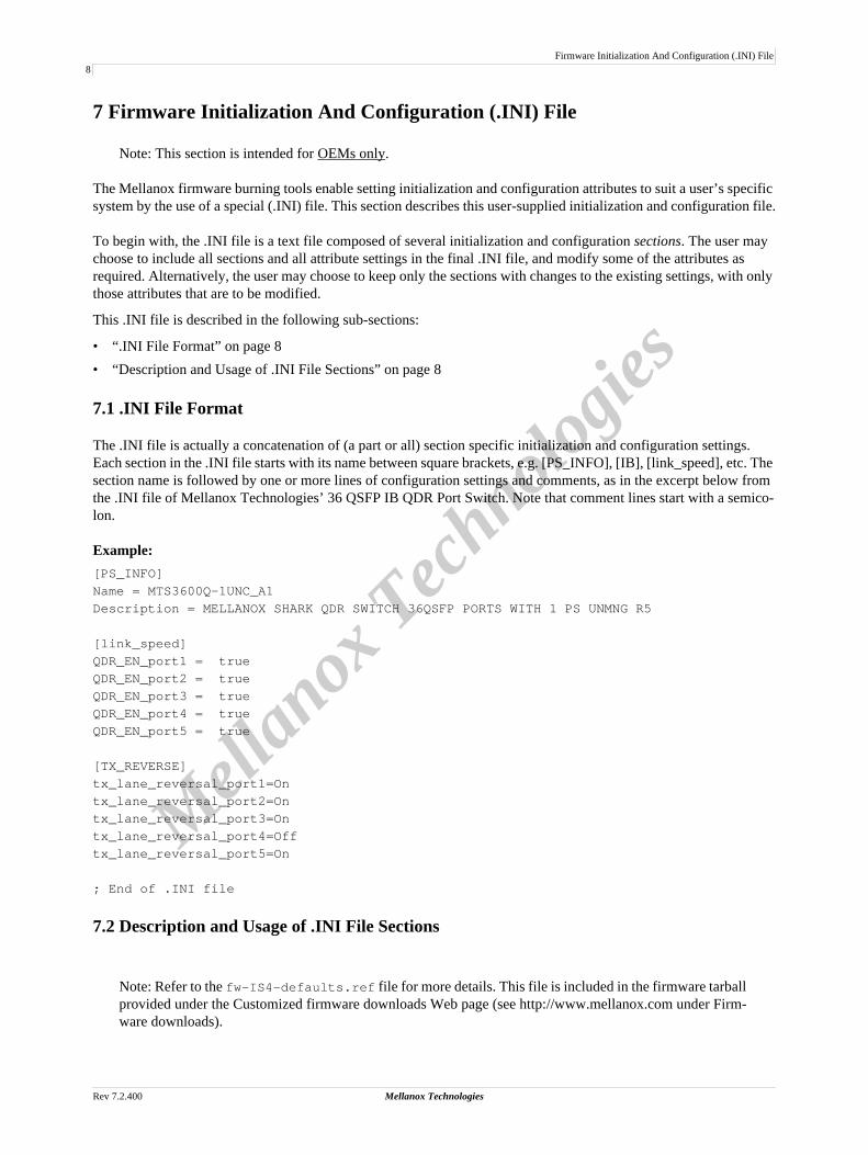
7.1 .INI File Format
The .INI file is actually a concatenation of (a part or all) section specific initialization and configuration settings. Each section in the .INI file starts with its name between square brackets, e.g. [PS_INFO], [IB], [link_speed], etc. The section name is followed by one or more lines of configuration settings and comments, as in the excerpt below from the .INI file of Mellanox Technologies’ 36 QSFP IB QDR Port Switch. Note that comment lines start with a semico-lon.
Example:[PS_INFO]Name = MTS3600Q-1UNC_A1Description = MELLANOX SHARK QDR SWITCH 36QSFP PORTS WITH 1 PS UNMNG R5
[link_speed]QDR_EN_port1 = trueQDR_EN_port2 = trueQDR_EN_port3 = trueQDR_EN_port4 = trueQDR_EN_port5 = true
[TX_REVERSE]tx_lane_reversal_port1=Ontx_lane_reversal_port2=Ontx_lane_reversal_port3=Ontx_lane_reversal_port4=Offtx_lane_reversal_port5=On
; End of .INI file
7.2 Description and Usage of .INI File Sections
Note: Refer to the fw-IS4-defaults.ref file for more details. This file is included in the firmware tarball provided under the Customized firmware downloads Web page (see http://www.mellanox.com under Firm-ware downloads).

InfiniScale IV fw-48436 Firmware Release Notes
Mellanox Technologies Rev 7.2.400
9
Mellan
ox Tech
nologie
s
The .INI file sections are:
1. [PS_INFO] – see Section 7.2.1 on page 92. [ADAPTER] – see Section 7.2.2 on page 93. [NODE_INFO] – see Section 7.2.3 on page 104. [IB] – see Section 7.2.4 on page 105. [SERDES] – see Section 7.2.5 on page 106. [LINK_SPEED] – see Section 7.2.6 on page 117. [LINK_WIDTH] – see Section 7.2.7 on page 128. [IB_TO_HW_MAP] – see Section 7.2.8 on page 149. [VL_CAP] – see Section 7.2.9 on page 1510. [IB_TO_LED_MAP] – see Section 7.2.10 on page 1511. [TX_REVERSE] – see Section 7.2.11 on page 1712. [RX_REVERSE] – see Section 7.2.12 on page 1713. [POLARITY] – see Section 7.2.13 on page 1814. [PORT_DISABLE] – see Section 7.2.14 on page 1815. [UNUSED_PORTS] – see Section 7.2.15 on page 1816. [EKEYING] – see Section 7.2.16 on page 1917. [PLL] – see Section 7.2.17 on page 1918. [GPIO] – see Section 7.2.18 on page 1919. [FW] – see Section 7.2.19 on page 19
7.2.1 [PS_INFO]This section provides firmware configuration (ini) information used by the IB Administration tools. It has no impact on the generated firmware image.
Example:Name = MTS3600Q-1UNC_A1 Description = MELLANOX SHARK QDR SWITCH 36QSFP PORTS WITH 1 PS UNMNG R5
7.2.2 [ADAPTER]This section provides product specific information such the following:
• PSID (parameter: PSID)On-switch adapter’s firmware configuration ID. This attribute can be assigned a string built from up to 16 char-acters of the set: [A-Z,0-9].
• Vendor ID (parameter: adapter_vendor_id)This parameter holds the Vendor ID of Mellanox Technologies: 0x15b3. It is reported to a QUERY_ADAPTER query by the driver.
• PCI Device ID and Revision ID (parameters: adapter_dev_id, adapter_rev_id)Used for identifying the switch over the PCI Express interface. They are reported to a QUERY_ADAPTER query by the driver. Both are integer parameters in the range 0x0 to 0xffff.
Firmware Initialization And Configuration (.INI) File
Rev 7.2.400 Mellanox Technologies
10
Mellan
ox Tech
nologie
s
Example:PSID = MT_0C20110003adapter_vendor_id = 0x15b3adapter_dev_id = 0xbd34adapter_rev_id = 0xa
7.2.3 [NODE_INFO]This section allows programming parameters such as SystemImageGUID, NodeGUID, and PortGUID.
7.2.4 [IB]This section defines InfiniBand specific information of the product such a the Mellanox IB Vendor ID (parameter: nodeinfo_vendor_id), Partition Table size supported by each port (parameter: nodeinfo_log_partition_cap), and others.
Example:
;;;;; Mellanox IB Vendor ID. A part of the Node Information that may be queried by the ;;;;; Subnet Manager (SM)nodeinfo_vendor_id = 0x2c9
;;;;; Log 2 of Partition Table size supported by each port.;;;;; Integer parameter. Values range : 0 - 7.
nodeinfo_log_partition_cap = 7
7.2.5 [SERDES]This section configures the SerDes of all the switch InfiniBand ports. Each port can be set to one of 16 possible con-figurations per port speed (SDR/DDR/QDR). Each configuration is defined by the following parameter types: eye pointer parameters, Tx parameters, and Rx parameters.
Tx parameters:1. ob_preemp_main - Range: 0x0-0x1f2. ob_preemp_post - Range: 0x0-0x1f3. ob_preemp_pre - Range: 0x0-0x1f4. preemp_mode - Range: 0x0-0x3
Rx parameters:1. extra_hs_gain - Range: 0x0-0x72. equal - Range: 0x0-0x7f3. muxmain - Range: 0x0-0x1f4. muxeq - Range: 0x0-0x1f5. main - Range: 0x0-0xf
By default, all ports are configured according to “generic” port parameters. Generic parameters have the following format:
InfiniScale IV fw-48436 Firmware Release Notes
Mellanox Technologies Rev 7.2.400
11
Mellan
ox Tech
nologie
s
{PARAM_NAME}_generic_{SPEED}_config{CONFIG_NUM}
where: {PARAM_NAME} is one of the SerDes parameters listed above; {SPEED} is SDR, DDR, or QDR; and {CONFIG_NUM} is an integer from 1 to 16.
To override the generic port configuration for a specific port, use the port configuration enable parameter en_serdes_conf_IbPortX (possible values: TRUE, FALSE) as follows:
en_serdes_conf_IbPortX=TRUE (X=1,2,...,36)
Port parameters are set using the following format:
{PARAM_NAME}_IbPort{PORT_NUM}_{SPEED}_config{CONFIG_NUM}
Warning: It is not recommended to modify the SerDes parameters without consulting Mellanox Tech-nologies as the parameters are set to standard and operational values by default.
Example:;;;; Enable ports 1-5 for non-generic configurationen_serdes_conf_IbPort1=TRUEen_serdes_conf_IbPort2=TRUEen_serdes_conf_IbPort3=TRUEen_serdes_conf_IbPort4=TRUEen_serdes_conf_IbPort5=TRUE
;;;;; Integer parameter. Values range : 0x0 - 0x7.extra_hs_gain_generic_SDR_config1 = 0x0extra_hs_gain_generic_SDR_config2 = 0x0extra_hs_gain_generic_SDR_config3 = 0x0extra_hs_gain_generic_SDR_config4 = 0x0extra_hs_gain_generic_SDR_config5 = 0x0;;;;; Integer parameter. Values range : 0x0 - 0x1f. muxeq_generic_QDR_config1 = 0x0muxeq_generic_QDR_config2 = 0x0muxeq_generic_QDR_config3 = 0x0muxeq_generic_QDR_config4 = 0x0muxeq_generic_QDR_config5 = 0x0ob_preemp_post_generic_QDR_config1 = 0x4ob_preemp_post_generic_QDR_config2 = 0x4ob_preemp_post_generic_QDR_config3 = 0x4ob_preemp_post_generic_QDR_config4 = 0x4ob_preemp_post_generic_QDR_config5 = 0x4
7.2.6 [LINK_SPEED]This section provides parameters for defining the maximum speed per port, and for enabling auto-negotiation of port speed. Table 7 lists and describes the parameters of this section and their possible configuration values.

Firmware Initialization And Configuration (.INI) File
Rev 7.2.400 Mellanox Technologies
12
Mellan
ox Tech
nologie
s
7.2.7 [LINK_WIDTH]The 36 physical IB ports of the InfiniScale IV are viewed as twelve 3-port clusters. Each such cluster gets a single command line in the [LINK_WIDTH] section to configure the link widths of its 3 ports. The configuration settings in this section determine both the LinkWidthSupported and the LINK_WIDTH attributes of all InfiniScale IV ports dur-ing boot.
The clusters are numbered cluster1 through cluster12, and the ports are assigned to these clusters in an ascending order. Thus, cluster1 groups ports 1, 2, and 3; cluster2 groups ports 4, 5, and 6;..., cluster12 groups ports 34, 35, and 36.
Per cluster, there are two parameters to set in this section: the maximum width in SerDes lanes supported by the Sub-net Manager for a cluster (width_enabled_clusterX, where X=1,2,...,12), and maximum width in SerDes lanes supported by the HW for a cluster (width_supported_clusterX, where X=1,2,...,12).
Table 6 - Link Speed Parameters and Configuration Values
Parameter Possible Configuration Values Resulting Cluster Configuration
SPEC1_2_portX(X=1,2,...,36)
TRUE The PHY is compliant with Release 1.2 of the InfiniBand Architecture Specifi-cation (specifically, the autonegotiation algorithm)
FALSE The PHY is not compliant with Release 1.2 of the InfiniBand Architecture Specification (specifically, the autonegotiation algorithm)
SDR_EN_portX(X=1,2,...,36)
TRUE Sets bit 0 (SDR) of the LinkSpeedEnabled field of Port X. A PortInfo Set() MAD can override this value.
NOTE: This bit must be set to enable the Mellanox speed auto-negotiation algo-rithm for this port.
FALSE Clears bit 0 of the LinkSpeedEnabled field of Port X. This setting disables speed auto-negotiation for this port.
DDR_EN_portX(X=1,2,...,36)
TRUE Sets bit 1 (DDR) of the LinkSpeedEnabled field of Port X. A PortInfo Set() MAD can override this value.
FALSE Clears bit 1 of the LinkSpeedEnabled field of Port X.
QDR_EN_portX(X=1,2,...,36)
TRUE Sets bit 2 (QDR) of the LinkSpeedEnabled field of Port X. A PortInfo Set() MAD can override this value.
FALSE Clears bit 2 of the LinkSpeedEnabled field of Port X.
speed_supported_portX(X=1,2,...,36)
SDR SDR is the only speed supported by HW for this port
SDR_DDR Both SDR and DDR speeds are supported by HW for this port
SDR_DDR_QDR SDR, DDR and QDR speeds are supported by HW for this port

InfiniScale IV fw-48436 Firmware Release Notes
Mellanox Technologies Rev 7.2.400
13
Mellan
ox Tech
nologie
s
Table 7 describes the possible configuration values for the couples of cluster parameters.
Note that in case a cluster is set as AUTOCONF_1X4X12X, then it may rise as a single 12X port or as three 4X ports, depending on the peer cluster capabilities at the time of link bring-up. This may occur in every instance of bring-up. Thus the cluster may start out as three 4X ports prior to link (re)establishment, and turn into a single 12X port after (re)establishment, or vice versa.
Example:width_enabled_cluster1 = LIKE_WIDTH_SUPPORTEDwidth_enabled_cluster2 = LIKE_WIDTH_SUPPORTEDwidth_enabled_cluster3 = LIKE_WIDTH_SUPPORTEDwidth_enabled_cluster4 = LIKE_WIDTH_SUPPORTEDwidth_enabled_cluster5 = LIKE_WIDTH_SUPPORTEDwidth_enabled_cluster6 = LIKE_WIDTH_SUPPORTEDwidth_enabled_cluster7 = LIKE_WIDTH_SUPPORTEDwidth_enabled_cluster8 = LIKE_WIDTH_SUPPORTEDwidth_enabled_cluster9 = LIKE_WIDTH_SUPPORTEDwidth_enabled_cluster10 = LIKE_WIDTH_SUPPORTEDwidth_enabled_cluster11 = LIKE_WIDTH_SUPPORTEDwidth_enabled_cluster12 = LIKE_WIDTH_SUPPORTED
width_supported_cluster1 = TRIO_1X4X
Table 7 - Configuration Values for Cluster Port Link Widths
Parameter Possible Configuration Values Resulting Cluster Configuration
width_enabled_clusterX(X=1,2,...,12)
LIKE_WIDTH_SUPPORTED If the Subnet Manager supports only configurations where all clusters have the same link width, set width_enabled_clusterX to LIKE_WIDTH_SUPPORTED for all the clusters, and choose the same value for width_supported_clusterX for all the clusters.
X4 The Subnet Manager supports a maximum link width of 4 SerDes for clusterX
X8 The Subnet Manager supports a maximum link width of 8 SerDes for clusterX
X12 The Subnet Manager supports a maximum link width of 12 SerDes for clusterX
width_supported_clusterX(X=1,2,...,12)
TRIO_1X The cluster is configured as 3 separate ports, each limited to 1X link width only
TRIO_1X4X The cluster is configured as 3 separate ports, each supporting 1X or 4X link width
TRIO_4X The cluster is configured as 3 separate ports, limited to 4X link width only
SINGLE_1X 1
1. If width_supported_clusterX (X=1,2,...,12) is set to one of the values SINGLE_1X, SINGLE_1X4X, SINGLE_1X4X8X, or SINGLE_1X4X8X12X, then the three HW ports of the cluster must be mapped to the same logical IB port.
The cluster is configured as a single port, limited to 1X link width only
SINGLE_1X4X 1 The cluster is configured as a single port supporting 1X and 4X link width
SINGLE_1X4X8X 1 The cluster is configured as a single port supporting 1X, 4X and 8X link width
SINGLE_1X4X8X12X 1 The cluster is configured as a single port supporting 1X, 4X, 8X, and 12X link widths
AUTOCONF_1X4X8X12X The cluster will auto-configure itself to match the configuration of the (peer) cluster connected to it through the IB cable

Firmware Initialization And Configuration (.INI) File
Rev 7.2.400 Mellanox Technologies
14
Mellan
ox Tech
nologie
s
width_supported_cluster2 = TRIO_1X4Xwidth_supported_cluster3 = TRIO_1X4Xwidth_supported_cluster4 = TRIO_1X4Xwidth_supported_cluster5 = TRIO_1X4Xwidth_supported_cluster6 = TRIO_1X4Xwidth_supported_cluster7 = TRIO_1X4Xwidth_supported_cluster8 = TRIO_1X4Xwidth_supported_cluster9 = TRIO_1X4Xwidth_supported_cluster10 = TRIO_1X4Xwidth_supported_cluster11 = TRIO_1X4Xwidth_supported_cluster12 = TRIO_1X4X
7.2.7.1 Link Width LockupAn IB port in a trio that is enabled for and configured to 4X width (4-SerDes port) by means of the width_enabled_clusterX and width_supported_clusterX parameters above may still be switched by the Subnet Manager to 1X width (1-SerDes port). To prevent this scenario, the user can enable the configuration parame-ter Link_Width_Lockup. This indicates to the Subnet Manager that a device port configured as a 4X port will not reconfigure to a 1X port even if asked to.
Possible values for the Link_Width_Lockup parameter are Disable (the default) and Enable.
Note: This mode of operation, where Link_Width_Lockup is enabled, serves as an extension to the func-tionlities defined in the InfiniBand Architecture Specification (Release 1.2).
Example:Link_Width_Lockup = Disable
7.2.8 [IB_TO_HW_MAP]This section maps the logical IB ports to the InfiniScale IV HW ports. The mapping is performed using the parame-ters PORTX (X=1,2,...,36) that identify the logical ports. Each such port is assigned a HW port that is represented by an integer value in the range 1-36.
Note: If width_supported_clusterX (X=1,2,...,12) is set to one of the values SINGLE_1X, SINGLE_1X4X, SINGLE_1X4X8X, or SINGLE_1X4X8X12X, then the three HW ports of the cluster must be mapped to the same logical IB port.
Example:
InfiniScale IV
Logical IB Port 1on chassis of InfiniScale IV
Chip Port 18 pins HW Port 18
18
Example:
Figure 1: Mapping a Chassis Logical IB Port to a HW Port
InfiniScale IV fw-48436 Firmware Release Notes
Mellanox Technologies Rev 7.2.400
15
Mellan
ox Tech
nologie
s
[IB_TO_HW_MAP]PORT1 = 18PORT2 = ......
7.2.9 [VL_CAP]This section is optionally used to set the
• maximum operational VLs for each port• mode of credit allocation between port VLs
Maximum Operational VLs:
Each port can be configured to operate one of the following maximum number of VLs: max_1_vls (1 VL), max_2_vls (2 VLs), max_4_vls (4 VLs), or max_8_vls (8 VLs). By default, all ports are set to max_8_vls as follows:
PORT1 = max_8_vlsPORT2 = max_8_vls...PORT35 = max_8_vlsPORT36 = max_8_vls
Note that the actual number of Operational VLs per port is set by the Subnet Manager. For more details, see the sec-tion titled “Credit Allocation for Virtual Lanes” in the MT48436 InfiniScale IV Programmer’s Reference Manual, Revision 0.21 or later, Document no. 2849PM.
Credit Allocation Mode:
The mode of credit allocation is set using the parameter Cred_Alloc_Mode. If this parameter is 0 (default), then credit allocation complies with the InfiniBand Architecture Specification: credits for a single MTU (2KB) packet are allo-cated for each VL numbered above 2OperationalVLs-1 up to 2VLCap-1, and the remaining credits are allocated between the Operational VLs according to the InfiniScale IV scheme of credit allocation. For more details, see the section titled “Credit Allocation for Virtual Lanes” in the MT48436 InfiniScale IV Programmer’s Reference Manual, Revi-sion 0.21 or later, Document no. 2849PM.
If Cred_Alloc_Mode is 1, credits are allocated to the Operational VLs only according to the InfiniScale IV scheme of credit allocation. VLs numbered above 2OperationalVLs-1 receive no credits at all.
Note: This mode (Cred_Alloc_Mode=1) is not compliant with the InfiniBand Architecture Specification.
7.2.10 [IB_TO_LED_MAP]The InfiniScale IV implements a built-in link indicator controller. The controller controls the status of 36 Yellow-Green LED pairs assigned to each InfiniBand port of the switch. The Green LED provides an indication on the phys-ical link state. When this LED is lit then the physical link is up. The Yellow LED indicates that the logical link is up, and its blinking rate indicates link activity.
The LEDs status is controlled through the pins LED_DATA[7:0] and LED_CLK[4:0] of the InfiniScale IV. Using the firmware configuration (.INI) file, the user can map each of the InfiniScale IV ports to a pair of consecutive
Firmware Initialization And Configuration (.INI) File
Rev 7.2.400 Mellanox Technologies
16
Mellan
ox Tech
nologie
s
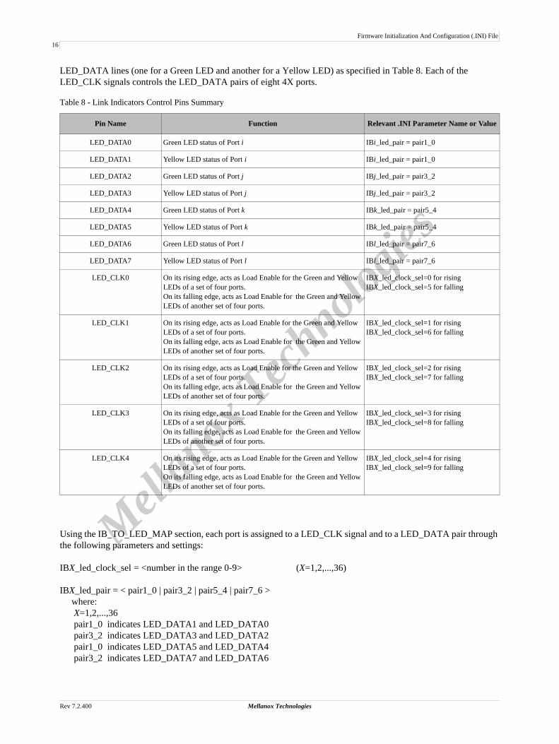
LED_DATA lines (one for a Green LED and another for a Yellow LED) as specified in Table 8. Each of the LED_CLK signals controls the LED_DATA pairs of eight 4X ports.
Using the IB_TO_LED_MAP section, each port is assigned to a LED_CLK signal and to a LED_DATA pair through the following parameters and settings:
IBX_led_clock_sel = <number in the range 0-9> (X=1,2,...,36)
IBX_led_pair = < pair1_0 | pair3_2 | pair5_4 | pair7_6 > where: X=1,2,...,36 pair1_0 indicates LED_DATA1 and LED_DATA0 pair3_2 indicates LED_DATA3 and LED_DATA2 pair1_0 indicates LED_DATA5 and LED_DATA4 pair3_2 indicates LED_DATA7 and LED_DATA6
Table 8 - Link Indicators Control Pins Summary
Pin Name Function Relevant .INI Parameter Name or Value
LED_DATA0 Green LED status of Port i IBi_led_pair = pair1_0
LED_DATA1 Yellow LED status of Port i IBi_led_pair = pair1_0
LED_DATA2 Green LED status of Port j IBj_led_pair = pair3_2
LED_DATA3 Yellow LED status of Port j IBj_led_pair = pair3_2
LED_DATA4 Green LED status of Port k IBk_led_pair = pair5_4
LED_DATA5 Yellow LED status of Port k IBk_led_pair = pair5_4
LED_DATA6 Green LED status of Port l IBl_led_pair = pair7_6
LED_DATA7 Yellow LED status of Port l IBl_led_pair = pair7_6
LED_CLK0 On its rising edge, acts as Load Enable for the Green and Yellow LEDs of a set of four ports.On its falling edge, acts as Load Enable for the Green and Yellow LEDs of another set of four ports.
IBX_led_clock_sel=0 for risingIBX_led_clock_sel=5 for falling
LED_CLK1 On its rising edge, acts as Load Enable for the Green and Yellow LEDs of a set of four ports.On its falling edge, acts as Load Enable for the Green and Yellow LEDs of another set of four ports.
IBX_led_clock_sel=1 for risingIBX_led_clock_sel=6 for falling
LED_CLK2 On its rising edge, acts as Load Enable for the Green and Yellow LEDs of a set of four ports.On its falling edge, acts as Load Enable for the Green and Yellow LEDs of another set of four ports.
IBX_led_clock_sel=2 for risingIBX_led_clock_sel=7 for falling
LED_CLK3 On its rising edge, acts as Load Enable for the Green and Yellow LEDs of a set of four ports.On its falling edge, acts as Load Enable for the Green and Yellow LEDs of another set of four ports.
IBX_led_clock_sel=3 for risingIBX_led_clock_sel=8 for falling
LED_CLK4 On its rising edge, acts as Load Enable for the Green and Yellow LEDs of a set of four ports.On its falling edge, acts as Load Enable for the Green and Yellow LEDs of another set of four ports.
IBX_led_clock_sel=4 for risingIBX_led_clock_sel=9 for falling

InfiniScale IV fw-48436 Firmware Release Notes
Mellanox Technologies Rev 7.2.400
17
Mellan
ox Tech
nologie
s
7.2.11 [TX_REVERSE]The transmit (Tx) SerDes of all IB ports support lane reversal. To configure the transmit SerDes of a port for lane reversal or no reversal, set the tx_lane_reversal_portX (X=1,2,...,36) parameter to on or off, respectively.
Example:tx_lane_reversal_port1 = ontx_lane_reversal_port2 = on
The tx_lane_reversal_autoflag_portX parameters enable or disable dynamic Tx lane reversal, i.e., turning reversal on/off during operation.
Example:tx_lane_reversal_autoflag_port1 = Offtx_lane_reversal_autoflag_port2 = Off
It is also possible to enable or disable Tx lane reversal within a cluster using the tx_rev_lane_IbClusterX parameter (X=1,2,...,36). Possible parameter values are: on for enabling reversal and off for disabling reversal.
Example:tx_rev_lane_IbCluster1 = Offtx_rev_lane_IbCluster2 = Offtx_rev_lane_IbCluster3 = Off
7.2.12 [RX_REVERSE]The receive (Rx) SerDes of all IB ports support lane reversal. To configure the Rx SerDes of a port for lane reversal or no reversal, or for auto-configuration, set the rx_lane_reversal_portX (X=1,2,...,36) parameter to on or off or auto, respectively.
Example:rx_lane_reversal_port1 = autorx_lane_reversal_port2 = autorx_lane_reversal_port3 = autorx_lane_reversal_port4 = offrx_lane_reversal_port5 = offrx_lane_reversal_port6 = off
It is also possible to enable, disable, or allow auto-configuration for Rx lane reversal within a cluster using the rx_rev_lane_IbClusterX parameter (X=1,2,...,36). Possible parameter values are: on for enabling reversal; off for disabling reversal; and auto for allowing auto-configuration.
Example:rx_rev_lane_IbCluster1 = autotx_rev_lane_IbCluster2 = Off

Firmware Initialization And Configuration (.INI) File
Rev 7.2.400 Mellanox Technologies
18
Mellan
ox Tech
nologie
s
tx_rev_lane_IbCluster3 = Off
7.2.13 [POLARITY]The InfiniScale IV hardware supports Tx and Rx SerDes (lane) polarity reversal for both Tx and Rx. By default, Tx and Rx SerDes polarity reversal is disabled.
7.2.13.1 Tx SerDes PolarityUse the tx_lane_polarity_portX (X=1,2,...,36) parameter to set the polarity of the Tx lanes within a 4X port. This paramter takes a 4-bit value between 0x0-0xf (0-15 decimal), with a 1 at bit i (i=0,1,2,3) indicates polarity rever-sal for lane i and a 0 indicates no polarity reversal.
Example:;; No polarity reversal on Port 1 Tx lanestx_lane_polarity_port1=0x0;; Polarity reversal on Tx lanes 0 and 1 of Port 1tx_lane_polarity_port1=0x3
7.2.13.2 Rx SerDes PolarityUse the rx_lane_polarity_portX (X=1,2,...,36) parameter to set the polarity of the Rx lanes within a 4X port. This paramter takes a 4-bit value between 0x0-0xf (0-15 decimal), with a 1 at bit i (i=0,1,2,3) indicates polarity rever-sal for lane i and a 0 indicates no polarity reversal.
Example:;; No polarity reversal on Port 1 Rx lanesrx_lane_polarity_port1=0x0;; Polarity reversal on Rx lanes 0 and 1 of Port 1rx_lane_polarity_port1=0x3
It is also possible to fix the Rx lanes polarity of a port (to prevent dynamic changes to polarity) using the rx_force_polarity_portX (X=1,2,...,36) parameter. By default, Rx lane polarity is not fixed (rx_force_polarity_portX=Disable). To fix the Rx lanes polarity, set the parameter value to Enable.
Example:rx_force_polarity_port1=Enablerx_force_polarity_port2=Disable
7.2.14 [PORT_DISABLE]By default, the initial state of all physical ports is Polling. This section provides the parameter disable_portX (X=1,2,...36) for changing the initial state to Disable. The parameter has two possible values: TRUE or FALSE
Example:disable_port1 = falsedisable_port2 = false
7.2.15 [UNUSED_PORTS]This section allows automatic shutdown of unused ports. This is provided via the hw_portX_not_in_use paramter (X=1,2,...,36). Set hw_portX_not_in_use to TRUE to enable automatic shutdown for an unused port, or set it to FALSE to prevent automatic shutdown for an unused port.

InfiniScale IV fw-48436 Firmware Release Notes
Mellanox Technologies Rev 7.2.400
19
Mellan
ox Tech
nologie
s
Example:hw_port1_not_in_use = falsehw_port2_not_in_use = false
7.2.16 [EKEYING]The InfiniScale IV supports port ekeying. Specifically, it allows electronic keying to shut down a port in case a proto-col other than InfiniBand is attempted on the port connection. Use the hw_port1_support_ekeying parameter to dis-able (FALSE) or enable (TRUE) port ekeying. By default, port ekeying is disbaled.
Example:hw_port1_support_ekeying = truehw_port2_support_ekeying = false
7.2.17 [PLL]This section provides parameters for PLL debug. It is intended for internal use.
7.2.18 [GPIO]This section provides parameters for setting special functionality for select GPIO pins.
By default, all GPIO pins are initially set as inputs. This is equal to setting the gpio_mode paramter to 0. Setting this parameter to 1 configures the GPIO pins as outputs.
Example:gpio_mode = 0x0
7.2.19 [FW]Use this section to set parameters relevant to the on-board Flash devices and their management.
To indicate the size of a single Flash device in bytes, enter its binary logarithm value (in the range 0-24).
Example:;; Flash device size is 2 MByteslog_flashdev_size = 21

History of Bug Fixes
Rev 7.2.400 Mellanox Technologies
20
Mellan
ox Tech
nologie
s
8 History of Bug Fixes
8.1 FW Version 7.1.000 Bug FixesN/A (first release of firmware)
8.2 FW Version 7.2.000 Bug FixesTable 9 - FW Version 7.2.000 Bug Fixes
Index Issue Description
1. Cannot set VL_CAP by ini Fixed (ID: 52924)
2. Non- qp0/qp1 packets to the SMA of an unmanaged switch hang the FW
Fixed (ID: 54031)
3. PKEY: Inbound P_Key Enforcement par-tial bit is set by default instead of cleared
Fixed (ID: 54030)
4. Symbol error counter of IB Port1 is not cleared after boot
Fixed
5. Mellanox auto-negotiation ini parameters ini values of auto-negotiation iteration 15 and 16 were ignored (all values set to zero)
6. PortCounters MAD: Cannot clear PortxM-mitWait counter using set()
Added PortXmitWait bit in the counterselect2 field (As per IBTA comment MGTWG2276-NEW) (ID: 55888)
7. Wrong capability mask in ClassPortInfo of performance management class
Fixed
8. Mellanox auto-negotiation: If NOI/NRI of peer device is higher than InfiniScale IV NOI/NRI values, SerDes parameters may all be set to zero
Fixed
9. Secondary I2C address conflicts with tem-perature sensor I2C address on Shark sys-tem
Changed the default secondary I2C slave address to 0x68 (used to be 0x48)
10. Cannot use MAD to open a port disabled by INI file
It is now possible to use a PortInfo MAD to open a port that was disabled by the port_disable parameter in the INI file

InfiniScale IV fw-48436 Firmware Release Notes
Mellanox Technologies Rev 7.2.400
21
Mellan
ox Tech
nologie
s
8.3 FW Version 7.2.100 Bug Fixes (Intermediate Release)
8.4 FW Version 7.2.200 Bug Fixes (Intermediate Release)
Table 10 - FW Version 7.2.100 Bug Fixes
Index Issue Description
1. command interface - using MAD_IFC causes unexpected behavior
Fixed
2. command interface - QUERY_FW does not support OpMod=0x2
Fixed
3. command interface - INIT_PORT and CLOSE_PORT are not supported
Fixed
4. command interface - bit BM in INIT_MAD_DEMUX is not supported
Fixed
5. HCA driver interface: HW2SW_DQ may post extra CQEs
Fixed
Table 11 - FW Version 7.2.200 Bug Fixes
Index Issue Description
1. Overtemp warning GPIO cannot be set The GPIO indicating the overtemp warning cannot be set because the support bit is miss-ing in the ini file. Status: Fixed

History of Bug Fixes
Rev 7.2.400 Mellanox Technologies
22
Mellan
ox Tech
nologie
s