release info tekla structures 21 - dl.construsoft.net
TRANSCRIPT

WWW.CONSTRUSOFT.COM A U T H O R I Z E DR E S E L L E R
Release Info
Tekla Structures 21.0

All rights reserved. No conclusions can be associated to the representation of the pictures in relation to the
operating systems under which Tekla Structures runs.
No part of the contents of this manual may be reproduced or transmitted in any form or by any means without
the permission of Construsoft B.V.
Construsoft B.V. is not responsible for any consequences as a result of using Tekla Structures.
This work is licensed under the Creative Commons Attribution-NonCommercial-NoDerivatives 4.0 Interna-
tional License. To view a copy of this license, visit http://creativecommons.org/licenses/by-nc-nd/4.0/ or send
a letter to Creative Commons, 444 Castro Street, Suite 900, Mountain View, California, 94041, USA.

© 2015 Tekla Corporation and its licensors. All rights reserved.
This Software Manual has been developed for use with the referenced Software. Use of the Software, and
use of this Software Manual are governed by a License Agreement. Among other provisions, the License
Agreement sets certain warranties for the Software and this Manual, disclaims other warranties, limits recov-
erable damages, defines permitted uses of the Software, and determines whether you are an authorized user
of the Software. All information set forth in this manual is provided with the warranty set forth in the License
Agreement. Please refer to the License Agreement for important obligations and applicable limitations and
restrictions on your rights. Tekla does not guarantee that the text is free of technical inaccuracies or typo-
graphical errors. Tekla reserves the right to make changes and additions to this manual due to changes in the
software or otherwise.
In addition, this Software Manual is protected by copyright law and by international treaties. Unauthorized
reproduction, display, modification, or distribution of this Manual, or any portion of it, may result in severe civil
and criminal penalties, and will be prosecuted to the full extent permitted by law.
Tekla, Tekla Structures, Tekla NIS, Tekla DMS, Tekla Municipality GIS, and Tekla Civil are either registered
trademarks or trademarks of Tekla Corporation in the European Union, the United States, and/or other coun-
tries. Other product and company names mentioned in this Manual are or may be trademarks of their respec-
tive owners. By referring to a thirdparty product or brand, Tekla does not intend to suggest an affiliation with or
endorsement by such third party and disclaims any such affiliation or endorsement, except where otherwise
expressly stated.
Portions of this software:
D-Cubed 2D DCM © 2008 Siemens Industry Software Limited. All rights reserved.
EPM toolkit © 1995-2004 EPM Technology a.s., Oslo, Norway. All rights reserved.
XML parser © 1999 The Apache Software Foundation. All rights reserved.
Project Data Control Library © 2006 - 2007 DlhSoft. All rights reserved.
DWGdirect, DGNdirect and OpenDWG Toolkit/Viewkit libraries © 1998-2005 Open Design Alliance. All rights
reserved.
FlexNet Copyright © 2010 Flexera Software, Inc. and/or InstallShield Co. Inc. All Rights Reserved. This prod-
uct contains proprietary and confidential technology, information and creative works owned by Flexera Soft-
ware, Inc. and/or InstallShield Co. Inc. and their respective licensors, if any. Any use, copying, publication,
distribution, display, modification, or transmission of such technology in whole or in part in any form or by any
means without the prior express written permission of Flexera Software, Inc. and/or InstallShield Co. Inc. is
strictly prohibited. Except where expressly provided by Flexera Software, Inc. and/or InstallShield Co. Inc. in
writing, possession of this technology shall not be construed to confer any license or rights under any Flexera
Software, Inc. and/or InstallShield Co. Inc. intellectual property rights, whether by estoppel, implication, or oth-
erwise.
The software is protected by U.S. Patent Nos. 7,302,368, 7,617,076, 7,765,240, 7,809,533, 8,022,953,
8,041,744 and 8,046, 210. Also elements of the software described in this Manual may be the subject of
pending patent applications in the European Union and/or other countries including U.S. patent applications
2005285881, 20110102463 and 20120022848.


Release Info Tekla Structures 21.0
Release Info Tekla Structures 21.0 ............................................................................ 1
Tekla Online Services ................................................................................................. 1
Tekla User Assistance ....................................................................................... 2
Tekla Warehouse.............................................................................................. 5
General ..................................................................................................................... 7
New notebox .................................................................................................... 7
Compatibility..................................................................................................... 7
Compatibility of Tekla Structures ........................................................................ 8
Tekla Structures 32-bit version ........................................................................... 8
Copying personal settings to a new Tekla Structures version ................................ 9
License Construsoft-developments ................................................................... 10
Speed improvements in Tekla Structures 21.0. .................................................. 10
Tekla multi-user server versus Windows Server 2003......................................... 10
Model templates version updates ..................................................................... 11
Construsoft Extranet........................................................................................ 12
Hexagonal profiles added ................................................................................ 12
Bolt standards added....................................................................................... 12
TeklaTimer ..................................................................................................... 13
Tekla Model Sharing ....................................................................................... 15
Improvements as a result of the User Feedback Program ................................... 17
Semicolons as path separators in folder paths ................................................... 18
Construsoft Auto Surface Replacer ................................................................... 18
Interoperability ......................................................................................................... 19
Export to IFC .................................................................................................. 19
Modeling.................................................................................................................. 22
Modify the shape and the location of objects ..................................................... 22
Snapping in clip planes.................................................................................... 23
Displaying gridline labels ................................................................................. 25
Splitting polybeams ......................................................................................... 26
Clash check between bolts and bolted parts ...................................................... 26
Inquire information about rebar cross sections ................................................... 28
Lambert coordinate information in object information .......................................... 30
Invisible contact planes for concrete parts ......................................................... 31
Improvements in pour breaks ........................................................................... 31
Reference models ........................................................................................... 32
System components ................................................................................................. 38
Updating system component settings................................................................ 38
Finish added................................................................................................... 39
Tensioner (7) .................................................................................................. 40
Windbrace gusset plate (16) ............................................................................ 43
Stiffened end plate (27) and Partial stiff end plate (65)........................................ 44
Stub (28) and Seating (30) ............................................................................... 44
Wood wall (57)................................................................................................ 45
Numbering UDA (73) ....................................................................................... 46
Area filled with slab (61) and Area filled with slab (62) ........................................ 46
Footplate (1029) ............................................................................................. 47
Concrete foundation (1030).............................................................................. 49

Release Info Tekla Structures 21.0
Multiple stiffeners (1064).................................................................................. 49
Custom components ................................................................................................. 50
Adding and moving custom parts in models....................................................... 50
zinkgaten profielen (tabel)................................................................................ 51
Willems Ankers Cross coupler added................................................................ 52
Plugins .................................................................................................................... 54
Help improvements ......................................................................................... 54
Bearingblocks on slabs (m058) ........................................................................ 55
Macros .................................................................................................................... 56
New tool CS_Parts_From_Excel ...................................................................... 56
CS Flip........................................................................................................... 56
Deleted macros............................................................................................... 57
Checking settings............................................................................................ 58
Drawings ................................................................................................................. 59
Defining drawing-view properties ...................................................................... 59
Improvements in the Drawing List ..................................................................... 62
Information from the Drawing List in reports....................................................... 63
Improved drawing settings for roof elements...................................................... 64
Define units in labels ....................................................................................... 65
Hide lines behind the bolt nut ........................................................................... 66
Marking reinforcement bar groups .................................................................... 66
Files in Tekla Structures 21.0 .................................................................................... 68
Updating settings ............................................................................................ 68
Notities .................................................................................................................... 69

Tekla Online Services 1
Release Info Tekla
Structures 21.0
Tekla Online Services
You can now use Tekla Online Services. The following services are included:
You use Tekla Downloads to download Tekla Structures-versions, updates and
also Tekla BIMsight.
Tekla User Assistance provides centralized access where you can find all Tekla
Structures-related information.
You use Tekla Warehouse as a service for sharing content, for example embeds
or profiles. You can download these from the Tekla Warehouse and use them in
Tekla Structures.
Accessing To get access to the Tekla Online Services, you need a Tekla Account and a valid
maintenance contract. This Tekla Account is linked to your company and the
maintenance of your Tekla Structures license(s).
You must activate a main account, for this, go to https://account.tekla.com
If your account (as a main account) is activated, you can also invite your
colleagues and add them to the Tekla Online Services.
You get access to the Tekla Online Services via http://www.tekla.com, next click
the button Tekla websites. You can also log in via Tekla Structures, in that case,
you have direct access to all services:
See also Click here in case you have problems logging in to Tekla User Assistance.

2 Tekla Online Services
Tekla User Assistance
Tekla User Assistance (TUA) has been improved and expanded.
Tekla User Assistance provides centralized access where you can find all Tekla
Structures-related information.
The service is available via https://teklastructures.support.tekla.com and via the
button F1 in Tekla Structures.
Once you are logged in, select the desired language and the desired Tekla
Structures-version in the list boxes before you start searching content.
Besides the Tekla Structures Help, helpdesk-related subjects and videos, the
service also includes many specific subjects, added by Construsoft:
For example all training manuals are available per configuration. You can open the
books on a new tab page or search in the table of contents:
A lot of plugins, macros and tools include an extended Help-file in
which you find a lot of detailed information about the usage and the
possibilities.

Tekla Online Services 3
The service also includes a powerful function for searching:
You can also save the link of a subject and browse to the subject again later on:
4 Tekla Online Services
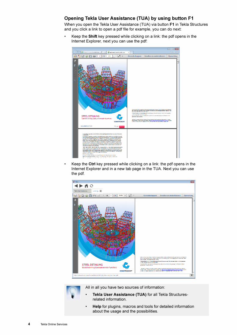
Opening Tekla User Assistance (TUA) by using button F1
When you open the Tekla User Assistance (TUA) via button F1 in Tekla Structures
and you click a link to open a pdf file for example, you can do next:
• Keep the Shift key pressed while clicking on a link: the pdf opens in the
Internet Explorer, next you can use the pdf:
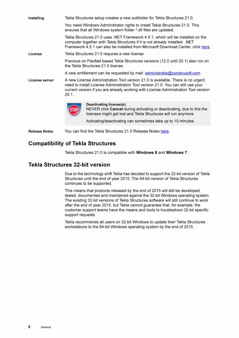
• Keep the Ctrl key pressed while clicking on a link: the pdf opens in the
Internet Explorer and in a new tab page in the TUA. Next you can use
the pdf.
All in all you have two sources of information:
• Tekla User Assistance (TUA) for all Tekla Structures-
related information.
• Help for plugins, macros and tools for detailed information
about the usage and the possibilities.

Tekla Online Services 5
Tekla Warehouse
With Tekla Structures 21.0, you can use Tekla Warehouse for collaboration, and for
storing and sharing Tekla Structures content.
Tekla Warehouse provides centralized access to a wide range of content that you
can use in your Tekla Structures model.
This can be custom components (such as embeds from Halfen or Peikko) or a set
of profiles you download from Tekla Warehouse and use in your model.
You can also add your content to Tekla Warehouse and publish this content for
everybody (online). You can also use the content for private use (local).
You can open Tekla Warehouse in Tekla Structures 21.0 via File > Open Tekla
Warehouse or click the icon.
When you open Tekla Warehouse for the first time, you login with your Tekla
account.
Tekla Warehouse includes many collections containing lots of content:
Tekla Warehouse also includes Tekla Structures collections, such as the collection
Construsoft Netherlands with lots of useful custom components and profiles.

6 Tekla Online Services
You can also search for specific content, the content is divided per
category:
Only by Construsoft added content is supported in Tekla Warehouse.
See also For more information on Tekla Warehouse, open Tekla Warehouse and click
About.

General 7
General
New notebox
In this Release Info will use a type of notebox with a specific picture and a
clarification to indicate that this subject is about settings you might have saved in
earlier Tekla Structures versions. These could be files in your model templates
and/or ts folder. These files have to be updated in Tekla Structures 21.0:
Compatibility
Tekla Structures 21.0 is a main version and contains many new features and fixes.
Tekla Structures 21.0 is compatible with all previous versions.
In case you still open existing models created in an older version in Tekla
Structures 21.0, note the following issues:
• Plugins can be combined causing only Tekla plugins available.
• To avoid conversion problems, always open a model created with an
older version of Tekla Structures as a single-user model first.
• We recommend that you always check that custom components created
in older versions work correctly in the new version of Tekla Structures.
When you open custom components made with an older version of
Tekla Structures in the Custom component editor, and the new version
contains improvements requiring update, Tekla Structures asks whether
you want to update the component. If you do not update the component,
it works in the same manner as in the version where it was originally
made, but you do not gain the benefits of the improvements. If you
choose to update the component, you need to check and sometimes
even recreate dimensions depending on the improvements. When you
delete a dimension and create a new one (even with the same name),
also the equations containing the dimension need to be edited, because
the dependency created by the equation is lost when a dimension is
deleted. You can recreate the dimensions and edit the equations easily
in the Custom component editor.
Clarification
Filename: Name of the file or extension.
You can open and edit existing models in Tekla Structures 21.0 but
we suggest that you complete any models you have started using
your current version.
When you save a model in Tekla Structures 21.0, you cannot open it
in older versions of Tekla Structures.
8 General
Installing Tekla Structures setup creates a new subfolder for Tekla Structures 21.0.
You need Windows Administrator rights to install Tekla Structures 21.0. This
ensures that all Windows system folder *.dll files are updated.
Tekla Structures 21.0 uses .NET Framework 4.5.1, which will be installed on the
computer together with Tekla Structures if it is not already installed. .NET
Framework 4.5.1 can also be installed from Microsoft Download Center, click here.
License Tekla Structures 21.0 requires a new license.
Previous on FlexNet based Tekla Structures versions (12.0 until 20.1) also run on
the Tekla Structures 21.0 license.
A new entitlement can be requested by mail: [email protected].
License server A new License Administration Tool version 21.0 is available. There is no urgent
need to install License Administration Tool version 21.0. You can still use your
current version if you are already working with License Administration Tool version
20.1.
Release Notes You can find the Tekla Structures 21.0 Release Notes here.
Compatibility of Tekla Structures
Tekla Structures 21.0 is compatible with Windows 8 and Windows 7.
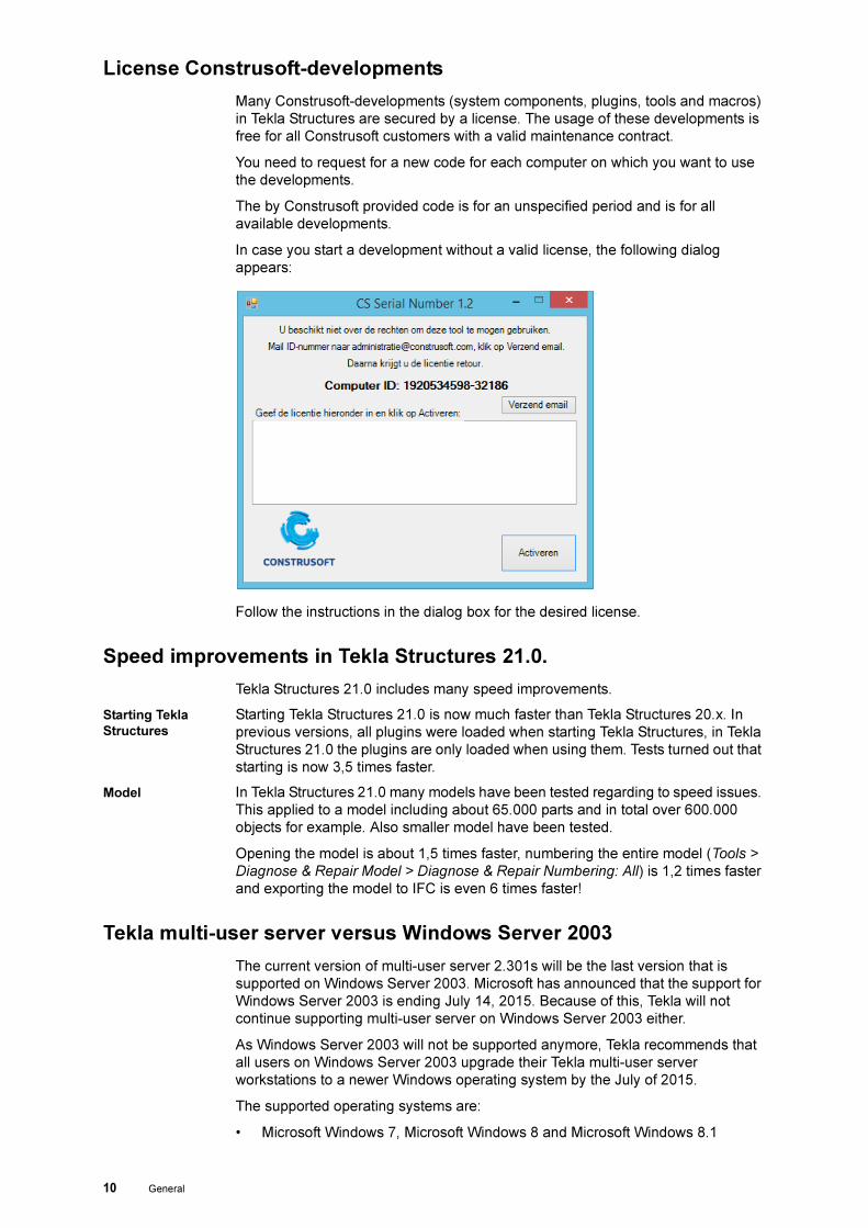
Tekla Structures 32-bit version
Due to the technology shift Tekla has decided to support the 32-bit version of Tekla
Structures until the end of year 2015. The 64-bit version of Tekla Structures
continues to be supported.
This means that products released by the end of 2015 will still be developed,
tested, documented and maintained against the 32-bit Windows operating system.
The existing 32-bit versions of Tekla Structures software will still continue to work
after the end of year 2015, but Tekla cannot guarantee that, for example, the
customer support teams have the means and tools to troubleshoot 32-bit specific
support requests.
Tekla recommends all users on 32-bit Windows to update their Tekla Structures
workstations to the 64-bit Windows operating system by the end of 2015.
Deactivating license(s):
NEVER click Cancel during activating or deactivating, due to this the
licenses might get lost and Tekla Structures will run anymore.
Activating/deactivating can sometimes take up to 10 minutes.

General 9
Copying personal settings to a new Tekla Structures version
You can copy personal settings from a previous Tekla Structures version to Tekla
Structures 21.0 by using the Migration wizard. This wizard opens automatically
when you start Tekla Structures 21.0 for the first time.
In dialog box Tekla Structures Migration wizard you can select which Tekla
Structures version you want to copy your personal setting from and to which Tekla
Structures version you want to copy the setting to.
Next you can select the personal settings, such as the user settings file user.ini
and registry values (e.g. added toolbars) you want to copy.
You can skip copying if you don’t want to copy settings or if you want to copy other
Tekla Structures version settings than the Migration wizard suggests.
Toolbars Recreate toolbars in case that icons appear as a red cross in the bar when copying
these from an earlier version. Red crosses appear if the corresponding command
does not exist anymore.
You can start the Migration wizard manually by double-clicking the
file MigrationWizard.exe in the folder ..\Tekla
Structures\<version>\nt\bin\applications\tekla\Mig
rations if you want to copy the settings later on.
10 General
License Construsoft-developments
Many Construsoft-developments (system components, plugins, tools and macros)
in Tekla Structures are secured by a license. The usage of these developments is
free for all Construsoft customers with a valid maintenance contract.
You need to request for a new code for each computer on which you want to use
the developments.
The by Construsoft provided code is for an unspecified period and is for all
available developments.
In case you start a development without a valid license, the following dialog
appears:
Follow the instructions in the dialog box for the desired license.
Speed improvements in Tekla Structures 21.0.
Tekla Structures 21.0 includes many speed improvements.
Starting Tekla
Structures
Starting Tekla Structures 21.0 is now much faster than Tekla Structures 20.x. In
previous versions, all plugins were loaded when starting Tekla Structures, in Tekla
Structures 21.0 the plugins are only loaded when using them. Tests turned out that
starting is now 3,5 times faster.
Model In Tekla Structures 21.0 many models have been tested regarding to speed issues.
This applied to a model including about 65.000 parts and in total over 600.000
objects for example. Also smaller model have been tested.
Opening the model is about 1,5 times faster, numbering the entire model (Tools >
Diagnose & Repair Model > Diagnose & Repair Numbering: All) is 1,2 times faster
and exporting the model to IFC is even 6 times faster!
Tekla multi-user server versus Windows Server 2003
The current version of multi-user server 2.301s will be the last version that is
supported on Windows Server 2003. Microsoft has announced that the support for
Windows Server 2003 is ending July 14, 2015. Because of this, Tekla will not
continue supporting multi-user server on Windows Server 2003 either.
As Windows Server 2003 will not be supported anymore, Tekla recommends that
all users on Windows Server 2003 upgrade their Tekla multi-user server
workstations to a newer Windows operating system by the July of 2015.
The supported operating systems are:
• Microsoft Windows 7, Microsoft Windows 8 and Microsoft Windows 8.1

General 11
• Microsoft Windows Server 2008 and Microsoft Windows Server 2008
R2
• Microsoft Windows Server 2012 and Microsoft Windows Server 2012
R2
Tekla does not guarantee that the products released after 14th of July 2015 and
later will work correctly on Windows Server 2003 or that Tekla service teams will
have the tools for solving Windows Server 2003 related questions.
Model templates version updates
In case you have created model template in earlier versions, you must update
these to use them hassle-free in Tekla Structures 21.0. Do the following:
1. Open Tekla Structures 21.0
2. Create a new model using an existing model template
3. Give it the same name as in the previous Tekla Structures version
4. Open the 3D model view
5. Diagnose and Repair the model (Tools > Diagnose & Repair Model)
6. Save the model as model template (File > Save as Model Template)
7. Select the required databases, model subfolders, drawing templates and
report templates and click OK:
The *.bak, *.log and xs_user files should be removed automatically from the
model directory
8. Remove all *.db (environment database, options databases) files from the
model directory manually.
The location of the model template is determined by the advanced option
XS_MODEL_TEMPLATE_DIRECTORY in Tools > Options > Advanced
options... > File Locations.

12 General
Construsoft Extranet
On 29 May 2015 the Construsoft Extranet closes.
As we suggested earlier in this document, you can use the Tekla Online Services
to find all Tekla Structures-related information. You use Tekla Downloads to
download Tekla Structures-versions, updates and also Tekla BIMsight. For
uploading models to the Construsoft Helpdesk, go to the pull-down menu Help >
Contact Tekla Support in Tekla Structures. Possibly you can also upload your
model via services such as WeTransfer.
Hexagonal profiles added
A number of hexagonal profiles have been added in Tekla Structures 21.0. As we
explained in Release Info 20.0, for some specific diameters the width across flats
has changed, such as bolt standard 4014: the width across flats for M10, M12,
M14 and M22 differ from standard DIN931:
According to the norm, the anchors are not categorized so far, this means that our
nuts still have the same width across flats and heights in the baseplate component
as it is in the standard 934. In case that the standard requires categorized anchors,
the hexagonal profiles are already available and you already have the necessary
profile cross sections.
Bolt standards added
The following bolt standards including bolts, nuts and washers are added to Tekla
Structures 21.0:
M10 17 to 16 M14 22 to 21
M12 19 to 18 M22 32 to 34
Bolt standard
EN14399-4-10.9 High strength bolts (DIN6914)
EN14399-4-10.9-8% High strength bolts (DIN6914) with square taper washer
UNP
EN14399-4-10.9-14% High strength bolts (DIN6914) with square taper washer
IPE
4017-PA Hexagonal tapping bolt (DIN933)
10642-RVS Countersunk bolts (DIN7991) Stainless steel
10642-8.8-ELVZ Countersunk bolts (DIN7991) zinc plated
10642-8.8-BOUT Countersunk bolts (DIN7991) only bolts
10642-10.9 Countersunk bolts (DIN7991)
4014-8.8-WTD Hexagonal bolt with Wyli Tension Disc
Clarification
Filename: assdb.db and screwdb.db
General 13
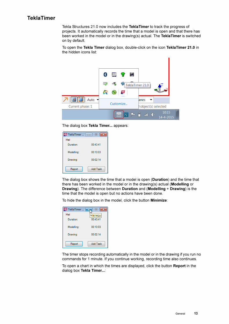
TeklaTimer
Tekla Structures 21.0 now includes the TeklaTimer to track the progress of
projects. It automatically records the time that a model is open and that there has
been worked in the model or in the drawing(s) actual. The TeklaTimer is switched
on by default.
To open the Tekla Timer dialog box, double-click on the icon TeklaTimer 21.0 in
the hidden icons list:
The dialog box Tekla Timer... appears:
The dialog box shows the time that a model is open (Duration) and the time that
there has been worked in the model or in the drawing(s) actual (Modelling or
Drawing). The difference between Duration and (Modelling + Drawing) is the
time that the model is open but no actions have been done.
To hide the dialog box in the model, click the button Minimize:
The timer stops recording automatically in the model or in the drawing if you run no
commands for 1 minute. If you continue working, recording time also continues.
To open a chart in which the times are displayed, click the button Report in the
dialog box Tekla Timer...:
14 General
By pressing the button Add task in the dialog box Tekla Timer..., you can add a
new task (time record), for example for additional work:
When you click in the dialog box Report view on the button Summary, a summary
in an Excel-sheet is displayed:

General 15
This sheet in saved in the model folder in the folder timerecord:
Restart the Tekla
Timer
When you close (unintentional) dialog box Tekla Timer..., the timer is turned off
and no time recording will take place anymore.
To restart the TeklaTimer, double-click the file TeklaTimer.exe in the folder
..:\21.0\nt\bin\applications\Tekla\ApplicationStartup
Remove Tekla
Timer
If you want to remove the TeklaTimer definitive, close Tekla Structures 21.0 and
delete, in the Windows Explorer, the following files from the folder
ApplicationStartup in
.:\TeklaStructures\21.0\nt\bin\applications\Tekla\
Tekla Model Sharing
Tekla Structures 21.0 offers new additional software Tekla Model Sharing. Using
Tekla Model Sharing is restricted. Click here before starting with Tekla Model
Sharing. Tekla Model Sharing enables global collaborative modeling within a Tekla
Structures model: team members now have the freedom to work with the same
model at the same time in different locations and time zones:
New York
London
Singapore

16 General
Benefit The main benefit of Tekla Model Sharing relative to the multi-user modus is the
data traffic. In the multi-user modus the entire workmodel is synchronized with the
mastermodel, in Tekla Model Sharing only changes are synchronized.
With Tekla Model Sharing you can invite other users to your shared model, join
someone else's shared model and share model changes
Tekla Model Sharing service
In Tekla Model Sharing each user has a local version of the model on their
computer or on a network drive, and the model data is shared and synchronized
over the Internet using a Microsoft Azure cloud service that is provided by Tekla.
When a model is shared, it is connected to the cloud-based sharing service. You
can then easily share your changes by writing out them to the sharing service.
When you want to update your model with the changes done by other users, you
do it by reading in the changes from the sharing service.
Even though the changes are shared over the Internet, you do not need to be
connected to the sharing service all the time. You need to be online only when you
want to write out or read in the changes. This enables the offline work if your
Internet connection is not always available.
You need to establish a connection to the Tekla Model Sharing service to perform
any model sharing actions and you also need a valid Tekla Account.
See also Click here for more detailed information about Tekla Model Sharing.
Click here for a video about how Tekla Model Sharing works.
Microsoft Azure
Kantoor 1 Kantoor 2
Lok Lok Lok Lok
Opslag voor
gedeelde
LAN LAN
Tekla Model
Tekla

General 17
Improvements as a result of the User Feedback Program
Tekla Structures includes the Automatic User Feedback Program (Help >
Automatic User Feedback Program).
This program collects information about your usage of Tekla Structures and sends
it back Tekla. This information is collected is used for fixing issues in Tekla
Structures and also to improve the software. The program is set by default, if
desired you can switch off the program if you don’t want to participate in it
anymore:
According to the feedback program, many users wanted to check the welded
main- and secondary part after welding manually. This now runs automatically.
When you now weld parts manually, the colored parts indicate the main (red) and
the secondary part (yellow):
Previous Tekla Structures-versions Tekla Structures 21.0

18 General
According to the feedback program also users very often changed the
representation of concrete parts after reinforcing the part to check the created
reinforcement. This now also runs automatically:
In earlier Tekla Structures-versions the representation of the concrete part
remained the same. This resulted in not showing the reinforcement immediately.
You could use shortkeys Ctrl + 1 till Ctrl + 4 to affect the representation of parts (to
show the reinforcement).
Semicolons as path separators in folder paths
The following environment variables now support semicolon-separated lists of
folder paths.
• DAK_BMPPATH
• XS_INP
• XS_TEMPLATE_DIRECTORY
• XS_TEMPLATE_DIRECTORY_SYSTEM
Earlier they only supported a single folder path.
Example set
XS_TEMPLATE_DIRECTORY_SYSTEM=%XSDATADIR%\environments\netherlands\t
emplate\
---->
set
XS_TEMPLATE_DIRECTORY_SYSTEM=%XSDATADIR%\environments\netherlands\t
emplate\;L:\ts_21\template
Construsoft Auto Surface Replacer
More often Tekla Structures and TeklaBIMsight are used for discussing offers,
meetings, etc.. In Tekla Structures, a model is created (general) and is used for
estimating costs or to clarify the construction.
Principals often cooperate with architects and they got used to work with real
design drafts including shadowing effects in a surrounding with accompanying
reference objects such as cars, humans and trees.
For our customers, the demand for professional illustrations for sales- and
presentation purposes, more and more increases.
To display models realistic, SketchUp now includes the Construsoft Auto
Surface Replacer to adjust the representation of a SketchUp model (exported
form Tekla Structures) fast and easily so that it is represented realistic in
SketchUp.
See also Click here for a document including detailed information, click here for the
SketchUp installation file.

Interoperability 19
Interoperability
Export to IFC
IFC export There are several improvements in IFC export in Tekla Structures 21.0:
• The performance of the IFC export has improved, and it is now much
faster to export to IFC.
• IFC output files and related log files are now saved by default to the \IFC
subfolder under the model folder.
• The Advanced tab of the Export to IFC dialog box has been organized
to three areas: Object types, Property sets and Other.
• The Use current view colors setting has been added on the Advanced
tab:
If you select Use current view colors, the exported objects have the colors that
you have defined using the color and transparency settings of Object groups
defined in the Object Representation dialog box.
In the Tekla
model

20 Interoperability
In TeklaBIMsight
If you do not select Use current view colors, the exported objects use the color
of the classes that are set for the objects in the properties dialog box:
• The View button for viewing the entity type and property set specific
property set file has been moved to the Property sets area on the
Advanced tab.
• You can now to export default property sets (Property sets: Default) or a
minimum amount of property sets (Property sets: Minimum). The Mini-
mum option exports a minimum amount of property sets required by the
buildingSMART IFC standard.
• The Load bearing property has been added on the Parameters tab of
the user-defined attributes dialog box of a part: Set the Load bearing
property to Yes to define the user-defined attribute LOAD_BEARING for
the exported object. Yes is the default value. Set this property to No for
all non-load bearing objects.
• The Accuracy property has been added to the Property Set Defini-
tions dialog box. When you can adjust the accuracy, you are able to
optimize the IFC file size better.

Interoperability 21
• The Positive length and Count options have been added to the Prop-
erty Set Definitions dialog box as measurement types.
• You can now export assemblies and cast units also as IfcRailing,
IfcRamp, IfcRoof and IfcStair, in addition to IfcElementAssembly.
• The IfcPropertySetConfigurations_AISC.xml file now supports the
property sets and the properties defined in the Steel fabrication view
and they are now available in Tekla Structures. Due to the limitations in
Tekla Structures, some properties cannot be provided.
• It is now possible to add property set properties also to IfcDiscreteAc-
cessory type of objects for sub-parts, and IfcOpeningElement type of
objects for bolt holes.
IFC object
converter
A summary of conversion results has been added to the Convert IFC objects
dialog box that shows errors in the conversion:
22 Modeling
Modeling
Modify the shape and the location of objects
Since Tekla Structures 20.0 you can use the command Direct modification to
easily modify model objects by simply dragging handles, without using the object
properties dialog boxes.
When you select an object in a model view, Tekla Structures displays handles and
dimensions that are specific for that model object. You can change the direct
modification dimensions by dragging the dimension arrowheads or by using the
Enter a Numeric Location dialog box.
You can see the result of direct modification immediately so you can model more
efficiently.
You can move handles of a contour plate by dragging the reference point handles:
To switch the command Direct modification on and off, click the icon in the
toolbar Selecting, use the shortkey Ctrl + D or go to Tools > Options > Direct
Modification.
In Tekla Structures 21.0 you can now modify construction points, construction
lines, construction circles and construction planes using direct modification.
By dragging direct modification handles and dimension arrowheads you can
easily:
• Move construction objects
• Change the length and direction of construction lines
• Change the radius of construction circles
• Change the dimensions and rotation of construction planes

Modeling 23
The command Direct modification is switched on in Tekla Structures 21.0 by
default.
When you switch of the command, the setting is stored in the model folder in the
file xs_user.username. If you are logged in as administrator, the name of this file
will be xs_user.administrator.
This file contains several settings. By renaming this file in the model folder to
xs_user.default and copying it to the folder ts, these settings will be taken into
account when creating new models.
Snapping in clip planes
When you use clip planes in model views in Tekla Structures 21.0, you can now
snap to points and lines in the clipped cross sections of model objects. The snap
symbol is bluish gray.
The work plane is set and you can snap now to create a dimension line, for
example:
You can also model objects.
In reference models, you can only snap to the corner points, not along the lines.

24 Modeling
The following example shows how you can easily model objects on sloped parts:

Modeling 25
Displaying gridline labels
You can now use quotation marks (" ") when defining gridline labels. Due to this
you can leave specific labels empty if this is required or you can use a name for a
label that consists of two separate names. See the following examples:
26 Modeling
Splitting polybeams
In Tekla Structures 21.0 you can split polybeams in models. You can split
polybeams in the same way as straight and curved parts by using the Edit > Split
command.
Due to this, the macro CS_Split_Polybeam (Tools > Macros) is not available
anymore.
After splitting, we recommend that you check that the position and orientation
settings of the split polybeams re correct: components related to the split
polybeams are deleted as they also were deleted in macro CS_Split_Polybeam.
Clash check between bolts and bolted parts
You can have Tekla Structures 21.0 search models for clashes that occur between
a bolt and the bolted parts. To do this, modify the clash check settings before you
use the Clash Check Manager to find clashes:
1. Click Tools > Options > Options.
2. In the Options dialog box, go to the Clash check page.
3. In the Clash check between bolt and bolted part list, select Yes.
4. Click OK.
Tekla Structures will check the bolts against the real geometry of the bolted part
profiles including roundings, and using the real bolt dimensions.

Modeling 27
Clarification
Filename: standard.opt.
28 Modeling
To highlight a clash in the model, select a row in the list of clashes. The related
model objects are selected.
You can also use the arrow up and down-buttons on your keyboard to go through
the list of the clashes in the Clash Check Manager to select the related model
objects in Tekla Structures.
To zoom the active view so that the selected objects are shown in the center of the
view, double-click a row:
Inquire information about rebar cross sections
If you now inquire information about reinforcing bars or a reinforcing bar group,
also the information about the cross section of the bars is displayed.
1. Click Tools > Inquire > Object or click the icon.
2. Select the reinforcing bars or reinforcing bar groups.

Modeling 29
You can also use the command Custom Inquiry (Tool > Inquire > Custom Inquiry)
to inquire information about one or more reinforcing bars or reinforcing bar groups
in the dialog box Custom Inquiry.
You can open the dialog box Custom Inquiry and drag it to any random position.
Every time you select reinforcement in the model, the information about the
selected part is displayed.
To display the reinforcement properties, you do the following:
1. Click Tools > Inquire > Custom Inquiry.
Dialog box Custom Inquiry opens.
2. Load the setting Wapening and select one or more reinforcing bars or
reinforcing bar groups.
Tekla Structures displays the information about the reinforcement:
If you select multiple reinforcing bars or reinforcing bar groups, the dialog box
displays the information about the counted square millimeters of the cross sections
(also for different diameters):

30 Modeling
To manage the content of the displayed information, click Manage contents... in
the dialog box.
See also For more information about managing the content of the dialog box, see the Tekla
User Assistance (F1).
Lambert coordinate information in object information
When you inquire object information in the model, the dialog box Inquire Object
now also displays the information about the Lambert coordinates.
You can define the values for the Lambert coordinates referencepoint in the tab
page Lambert coordinates (via File > Project Properties):
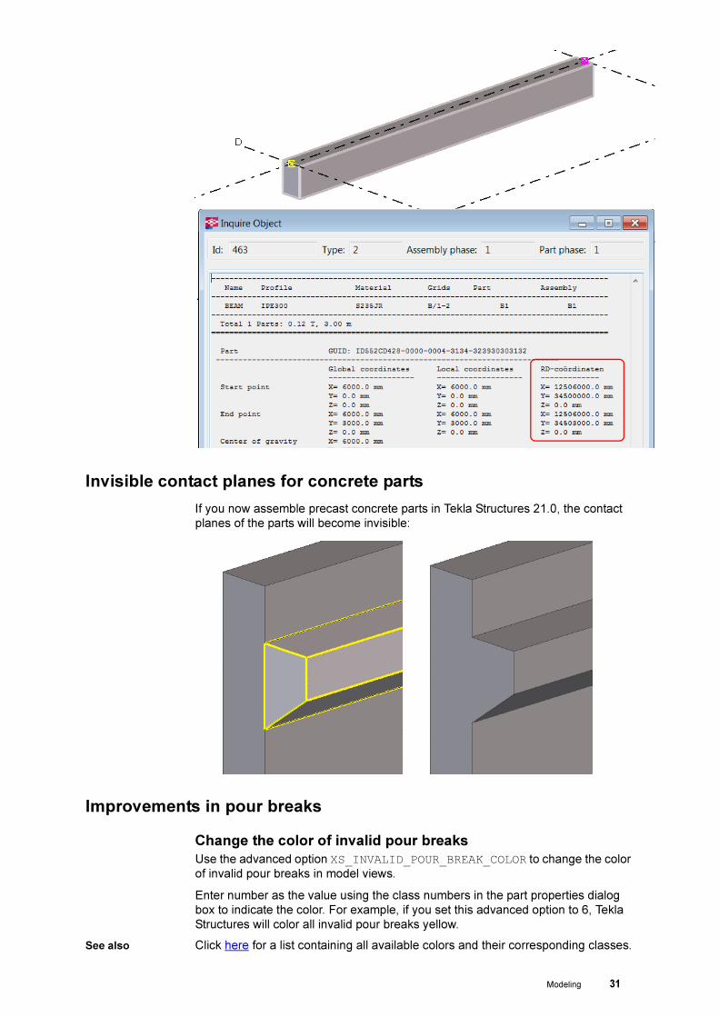
Modeling 31
Invisible contact planes for concrete parts
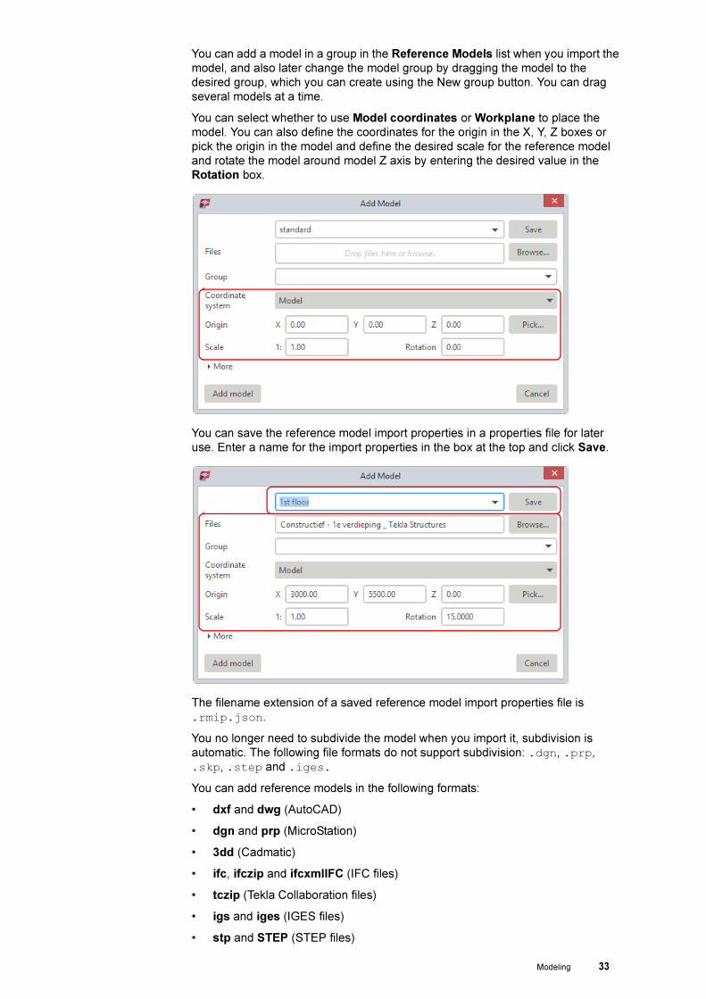
If you now assemble precast concrete parts in Tekla Structures 21.0, the contact
planes of the parts will become invisible:
Improvements in pour breaks
Change the color of invalid pour breaks
Use the advanced option XS_INVALID_POUR_BREAK_COLOR to change the color
of invalid pour breaks in model views.
Enter number as the value using the class numbers in the part properties dialog
box to indicate the color. For example, if you set this advanced option to 6, Tekla
Structures will color all invalid pour breaks yellow.
See also Click here for a list containing all available colors and their corresponding classes.

32 Modeling
Change the color of pour breaks
Use the advanced option XS_POUR_BREAK_COLOR (Tools > Options >
Advanced options category Concrete Detailling) to change the color of pour
breaks in model views.
Enter number as the value using the class numbers in the part properties dialog
box to indicate the color. For example, if you set this advanced option to 6, Tekla
Structures will color all pour breaks yellow. The default value is 59. In the exported
IFC models, pour breaks are black.
Change the color of pour objects
Use the advanced option XS_POUR_OBJECT_COLOR to change the default color of
pour objects in model views. Enter number as the value using the class numbers in
the part properties dialog box to indicate the color. For example, if you set this
advanced option to 6, Tekla Structures will color all pour objects yellow. The default
value is 110.
In the exported models, pour objects have the default value (110) and color (pink).
See also Click here for more information about the improvements regarding to pour objects
and pour breaks.
Reference models
Tekla Structures 21.0 offers a completely new approach for handling the reference
model import: the new Reference Models list is located in the new side pane, and
the renewed reference model management is easier and simpler.
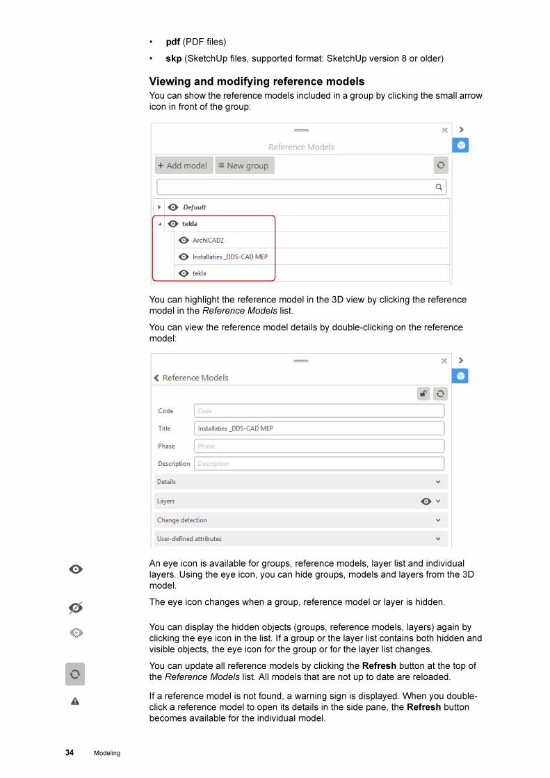
Adding a new reference model
You can add a new reference model by clicking the button Add model in the
Reference Models list.
You can load predefined import properties by entering or selecting the name of the
file in the box at the top.
You can browse for the reference model file or drag models from Windows
Explorer. It is possible to drag several models at a time.
Modeling 33
You can add a model in a group in the Reference Models list when you import the
model, and also later change the model group by dragging the model to the
desired group, which you can create using the New group button. You can drag
several models at a time.
You can select whether to use Model coordinates or Workplane to place the
model. You can also define the coordinates for the origin in the X, Y, Z boxes or
pick the origin in the model and define the desired scale for the reference model
and rotate the model around model Z axis by entering the desired value in the
Rotation box.
You can save the reference model import properties in a properties file for later
use. Enter a name for the import properties in the box at the top and click Save.
The filename extension of a saved reference model import properties file is
.rmip.json.
You no longer need to subdivide the model when you import it, subdivision is
automatic. The following file formats do not support subdivision: .dgn, .prp,
.skp, .step and .iges.
You can add reference models in the following formats:
• dxf and dwg (AutoCAD)
• dgn and prp (MicroStation)
• 3dd (Cadmatic)
• ifc, ifczip and ifcxmlIFC (IFC files)
• tczip (Tekla Collaboration files)
• igs and iges (IGES files)
• stp and STEP (STEP files)
34 Modeling
• pdf (PDF files)
• skp (SketchUp files, supported format: SketchUp version 8 or older)
Viewing and modifying reference models
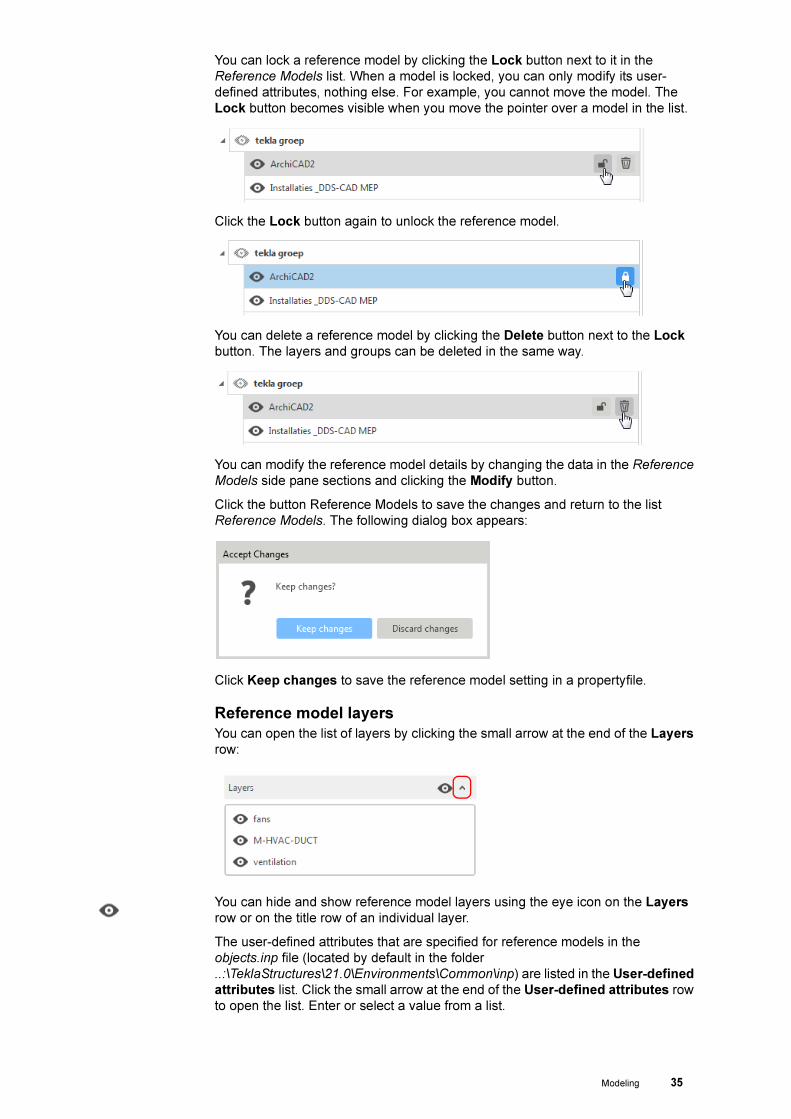
You can show the reference models included in a group by clicking the small arrow
icon in front of the group:
You can highlight the reference model in the 3D view by clicking the reference
model in the Reference Models list.
You can view the reference model details by double-clicking on the reference
model:
An eye icon is available for groups, reference models, layer list and individual
layers. Using the eye icon, you can hide groups, models and layers from the 3D
model.
The eye icon changes when a group, reference model or layer is hidden.
You can display the hidden objects (groups, reference models, layers) again by
clicking the eye icon in the list. If a group or the layer list contains both hidden and
visible objects, the eye icon for the group or for the layer list changes.
You can update all reference models by clicking the Refresh button at the top of
the Reference Models list. All models that are not up to date are reloaded.
If a reference model is not found, a warning sign is displayed. When you double-
click a reference model to open its details in the side pane, the Refresh button
becomes available for the individual model.
Modeling 35
You can lock a reference model by clicking the Lock button next to it in the
Reference Models list. When a model is locked, you can only modify its user-
defined attributes, nothing else. For example, you cannot move the model. The
Lock button becomes visible when you move the pointer over a model in the list.
Click the Lock button again to unlock the reference model.
You can delete a reference model by clicking the Delete button next to the Lock
button. The layers and groups can be deleted in the same way.
You can modify the reference model details by changing the data in the Reference
Models side pane sections and clicking the Modify button.
Click the button Reference Models to save the changes and return to the list
Reference Models. The following dialog box appears:
Click Keep changes to save the reference model setting in a propertyfile.
Reference model layers
You can open the list of layers by clicking the small arrow at the end of the Layers
row:
You can hide and show reference model layers using the eye icon on the Layers
row or on the title row of an individual layer.
The user-defined attributes that are specified for reference models in the
objects.inp file (located by default in the folder
..:\TeklaStructures\21.0\Environments\Common\inp) are listed in the User-defined
attributes list. Click the small arrow at the end of the User-defined attributes row
to open the list. Enter or select a value from a list.

36 Modeling
Detecting changes between reference models
You can check the changes between the old and the new reference model in Tekla
Structures by using the Change detection feature.
1. Open a model that contains a newer version of a reference model, and double-
click the reference model in the Reference Models list to open the details.
2. Go to the Change detection section and import a newer version of the same
reference model.
3. Click one or all of the options Changed , Inserted , Unchanged or Deleted and
then click Update view to show the changes in the model.
4. In the example below, one column has been deleted in the newer version of
the model, and it has been marked in red.

Modeling 37
Organizing models with the new Organizer
Tekla Structures includes the Organizer for managing model information and
classifying object properties.
1 = Object Browser
2 = Categories
You can use the Organizer for grouping model objects and classify them for
different purposes to instantly view the object properties from the model. The
Organizer consists of two tools:
Object Browser To instantly inquire and view the information (such as material, profiles, weights or
volumes) of one or more objects, phases, lots. You can determine the needed
information to be displayed. You can also export the inquired information to
Microsoft Excel.
Tekla Structures 21.0 includes the new setting Merkenposlijst:
Categories For classifying and grouping model objects for specific purposes. By using
categories, it is easy to track for example (to) heavy prefab- or steel elements, (to)
long reinforcing bars and trace the status information automatically. The
information in the Organizer is always up-to-date as you can synchronize it with
the model. In Categories you define building locations to automatically arrange
model objects and visualize the locations in the model.
See also Click here for more information about the Organizer.

38 System components
System components
Updating system component settings
Several system components from Construsoft are taken over by Tekla:
Concrete
segment
• Embedded anchors (8)
• Anchor (10)
• Wall wall teeth (12)
• Column - beam (14)
• Export Unitechnik (79)
• Parts at beam (82)
• Electric box in wall (84)
• Braced girder creation (88)
• Braced girder creation (89)
• Concrete console (110)
• Concrete console (111)
• Concrete beam - beam (112)
• Embed (1008)
• Precast found block (1028)
• Concrete foundation (1030)
Steel segment • Offshore (9)
• Column - 2 beam (14)
• Rectangle to circle (17)
• Triangles generation (19)
• Unfold surface (21)
• Generation of purlins (50)
• Squeezed tube bolted (102)
• Squeezed tube (103)
Due to this, the file extensions are changed so that all by Construsoft supplied
default settings now include the correct file extensions in Tekla Structures 21.0:
When you copy your personal settings from the mentioned system components
above, from an earlier Tekla Structures-version to Tekla Structures 21.0, you will
have to update these settings.
To update (rename) these file extensions fast and faultless to the new valid file
extensions, you can use the batch file
RenameConstrusoft2TeklaComponentAttributeSettings.bat.

System components 39
This file is located in the folder
..:\TeklaStructures\21.0\Environments\netherlands\system
Copy this batch file to the folder in which your personal settings are stored (the
folder ts, local on a workstation or somewhere on a server) and double-click on
the file: the file extensions are now renamed.
Next start Tekla Structures 21.0 and you will have the correct settings for the
mentioned system components.
Finish added
The following system components now include the option Finish:
• Bolted gusset (11)
• Joining plates (14)
• Stiffened end plate (27)
• Haunch (40)
• Cranked beam (41)
• Area filled with slabs (61)
• Area filled with slabs (62)
• Partial stiff end plate (65)
• Clip angle (141)
• Two sided end plate (142)
• Two sided clip angles (143)
• End plate detail (1002)
• Multiple stiffeners (1064)

40 System components
Tensioner (7)
System component Tensioner (7) now includes the new tab page UDA to define
the user-defined attributes (additional information about the parts) for the plate and
the fork:
For the fork, there is also template gaffel_merk.tpl available in which the
mentioned user-defined attributes of the fork are displayed in the drawing. This
template only appears in drawings in which the name GAFFEL has been used for
the part.
The template is listed in the table layout gaffel as a part of the new single part
drawing setting willems_anker_gaffel.

System components 41
The single part drawing of the fork looks as follows:
The fork is not dimensioned in the drawing because it concerns a purchase article!

42 System components
The single part drawing setting willems_anker_gaffel makes the name of the fork
looks as follows:
This makes it easy to filter the forks in the drawing list.
Halfen System component Tensioner (7) now also includes a new list box with Halfen
plates. These plates are part of the DETAN Rod System from Halfen:

System components 43
See also Click here for more information about the DETAN Rod System from Halfen.
Windbrace gusset plate (16)
Tekla Structures 21.0 now includes the new system component Windbrace
gusset plate (16) to model gusset plates including a specific slotted hole.
44 System components
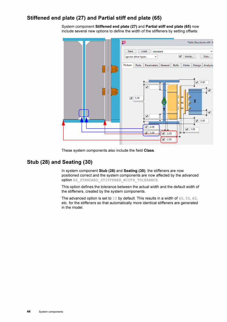
Stiffened end plate (27) and Partial stiff end plate (65)
System component Stiffened end plate (27) and Partial stiff end plate (65) now
include several new options to define the width of the stiffeners by setting offsets:
These system components also include the field Class.
Stub (28) and Seating (30)
In system component Stub (28) and Seating (30), the stiffeners are now
positioned correct and the system components are now affected by the advanced
option XS_STANDARD_STIFFENER_WIDTH_TOLERANCE.
This option defines the tolerance between the actual width and the default width of
the stiffeners, created by the system components.
The advanced option is set to 10 by default. This results in a width of 40, 50, 60,
etc. for the stiffeners so that automatically more identical stiffeners are generated
in the model.

System components 45
Wood wall (57)
System component Wood wall (57) now includes several new options.
In tab Picture you can define more layers (3 on each side of the frame):
You can use the listboxes to define the parts you want to create.
Previously, a truss (column) was created at the end of the frame. This is now fixed
and a triangular frame is created:

46 System components
Numbering UDA (73)
System component Numbering UDA (73) by which you can set the numbering of
parts has been deleted from Tekla Structures.
If this component was used, curved beams became straight and if there was
defined a finish in the profile properties, the information was deleted.
You can now use the tool CS_Write_Numbering_Results_Into_UDA (Tools >
Macros) for this.
This tool includes the same options as in system component Numbering UDA
(73) and includes a number of default settings:
See also Click the Help button in the dialog box of the tool for more detailed information
about how to use this tool and its possibilities.
Area filled with slab (61) and Area filled with slab (62)
System component Area filled with slab (61) and Area filled with slab (62) now
includes an option to create a specific recess.
For this, you can use the field Cutout Z gap in tab Plate geometry:

System components 47
Both system components now also include the option Finish on tab 1st Layer:
Footplate (1029)
The layout in tab Bolts for system component Footplate (1029) has been
corrected:

48 System components
Using Custom
parts
In tab page Anchor bolts you have a new option to use a Custom part, if required
with bolts or anchors.
When you select the new options Custom part, Bolts and custom part or
Anchors with custom comp. part, the fields for Partname component will
become visible automatically. Here you can define the custom components name
and the desired setting. You can also define the position:

System components 49
Concrete foundation (1030)
System component Concrete foundation (1030) now includes a new listbox in
which you can define the dimensions for the bended bars:
Multiple stiffeners (1064)
System component Multiple stiffeners (1064) now only includes the settings
standard and multiple. In earlier Tekla Structures versions the component
included a huge number of settings.
These settings are not required anymore, system component Multiple stiffeners
(1064) is now affected by the advanced option
XS_STANDARD_STIFFENER_WIDTH_TOLERANCE. The advanced option is set to
10 by default. This means that the width of the created stiffeners is 40,50, 60, etc.
This means that there is no need for the old settings anymore.
Use the advanced option XS_STANDARD_STIFFENER_WIDTH_TOLERANCE to
define the tolerance between the actual and standard widths of stiffener plates by
Haunch (40), Stiffeners (1003) and Multiple stiffeners (1064).

50 Custom components
Custom components
Adding and moving custom parts in models
In Tekla Structures 21.0, you can use the command Direct modification to add
custom parts from the Component Catalog to the model, and to move and rotate
the existing custom parts in the model.
You must switch the command Direct modification on.
The custom parts that you add can have one or two input points. The custom parts
may be created in Tekla Structures, or imported or downloaded, for example, from
Tekla Warehouse.
In direct modification of custom parts, you can easily drag coordinate axes,
rotation handles, and location dimensions to new locations, and in that way modify
and fine-tune the location and rotation of custom parts.
Positioning a
lifting anchor
Rotating a gain

Custom components 51
zinkgaten profielen (tabel)
Besides custom component zinkgaten profielen you can also use custom
component zinkgaten profielen (tabel):
Custom component zinkgaten profielen (tabel) makes use of a table (the file
sinkholes.dat). The file is located in the folder:
..:\TeklaStructures\21.0\Environments\netherlands\profil
The table includes profiles (HEA-, HEB- and HEM) and the corresponding sinkhole
diameter and centre to centre distance.
The holes (and the corresponding diameter and and centre to centre distance) are
created on base of the selected profile.
If desired, you can extend or modify the content of the table.
Ø 14
HEA140

52 Custom components
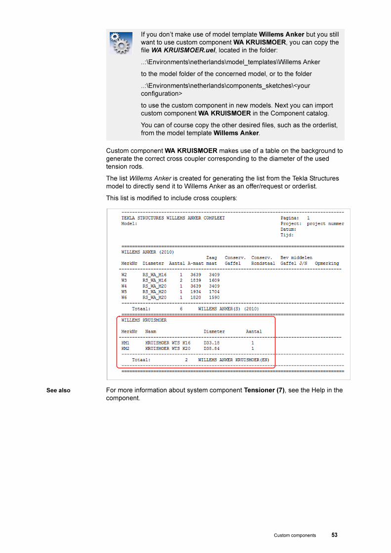
Willems Ankers Cross coupler added
Tekla Structures 21.0 now includes custom component WA KRUISMOER to model
cross couplers in Tekla Structures. The component creates a cross coupler
between the tension rods:
Custom component WA KRUISMOER is available when creating a new model
based on model template Willems Anker:
Because of this, your new model will include some specific setting files and a list to
order the Tensioner parts. These files are not includes in the default installation!
The Component Catalog includes the group Willems Anker. Inhere you can find
custom component KRUISMOER and some more Willems Anker related
components:
Custom components 53
Custom component WA KRUISMOER makes use of a table on the background to
generate the correct cross coupler corresponding to the diameter of the used
tension rods.
The list Willems Anker is created for generating the list from the Tekla Structures
model to directly send it to Willems Anker as an offer/request or orderlist.
This list is modified to include cross couplers:
See also For more information about system component Tensioner (7), see the Help in the
component.
If you don’t make use of model template Willems Anker but you still
want to use custom component WA KRUISMOER, you can copy the
file WA KRUISMOER.uel, located in the folder:
..:\Environments\netherlands\model_templates\Willems Anker
to the model folder of the concerned model, or to the folder
..:\Environments\netherlands\components_sketches\<your
configuration>
to use the custom component in new models. Next you can import
custom component WA KRUISMOER in the Component catalog.
You can of course copy the other desired files, such as the orderlist,
from the model template Willems Anker.

54 Plugins
Plugins
Help improvements
A large number of plugins, macros and tools now include an extended Help-file in
which you can find detailed information about the usage and the possibilities:

Plugins 55
Bearingblocks on slabs (m058)
Tekla Structures 21.0 includes a new plugin Bearingblocks on slabs (m058) to
model bearingblocks under hollow core slabs:

56 Macros
Macros
New tool CS_Parts_From_Excel
Tekla Structures 21.0 now includes the new tool CS_Parts_From_Excel to import
profiles from an Excel-file which is generated in software for analysis.
You can write the start and endpoints for profiles in the Excel-file and next import
the profiles in Tekla Structures by using this macro.
The most common analysis software programs, such as Rstab from Dlubal, are
able to generate such Excel-files including these profile points (and sections).
CS Flip
Tekla Structures includes the tool CS_Flip to modify the position, the direction and/
or the orientation for parts.
The tool has been improved in Tekla Structures 21.0 and you can now use the tool
for items as well.

Macros 57
Items You can use items in Tekla Structures to model objects that would be difficult to
model using basic Tekla Structures parts and commands, such as complex 3D
objects, for example anchors, clips or roofing tiles:
Items are similar to other parts in Tekla Structures, such as beams and columns.
The main difference between items and other types of parts is that a 3D shape
defines the geometry of an item, whereas a part has a 2D profile that is extruded to
create the length of the part.
Deleted macros
The macros CS_Assembly_sequencer and CS_Autosequencer, for assigning
control numbers, are deleted from Tekla Structures.
You can use macro CS_Sequence Tool for this, this macro includes many more
options.
See also Click on the button Help in the dialog box in the macro.

58 Macros
Checking settings
The tools CS_Write_Numbering_Results_Into_UDA, CS_Phase_Copy_Tool
and CS_Fill_UDA_From_Excel are rewritten to make the corresponding Help-
files working.
Because of this, all settings had to be saved again:
Update your personal settings!
Filename tool CS_Write_Numbering_Results_Into_UDA:
*.CS_Write_Numbering_Results_Into_UDA_ML006.MainForm.xml
Filename tool CS_Phase_Copy_Tool:
*.PhaseCopyTool.Form1.xml
Filename tool CS_Fill_UDA_From_Excel:
*.CS_Fill_UDA_From_Excel.MainDialog.xml
Drawings 59
Drawings
Defining drawing-view properties
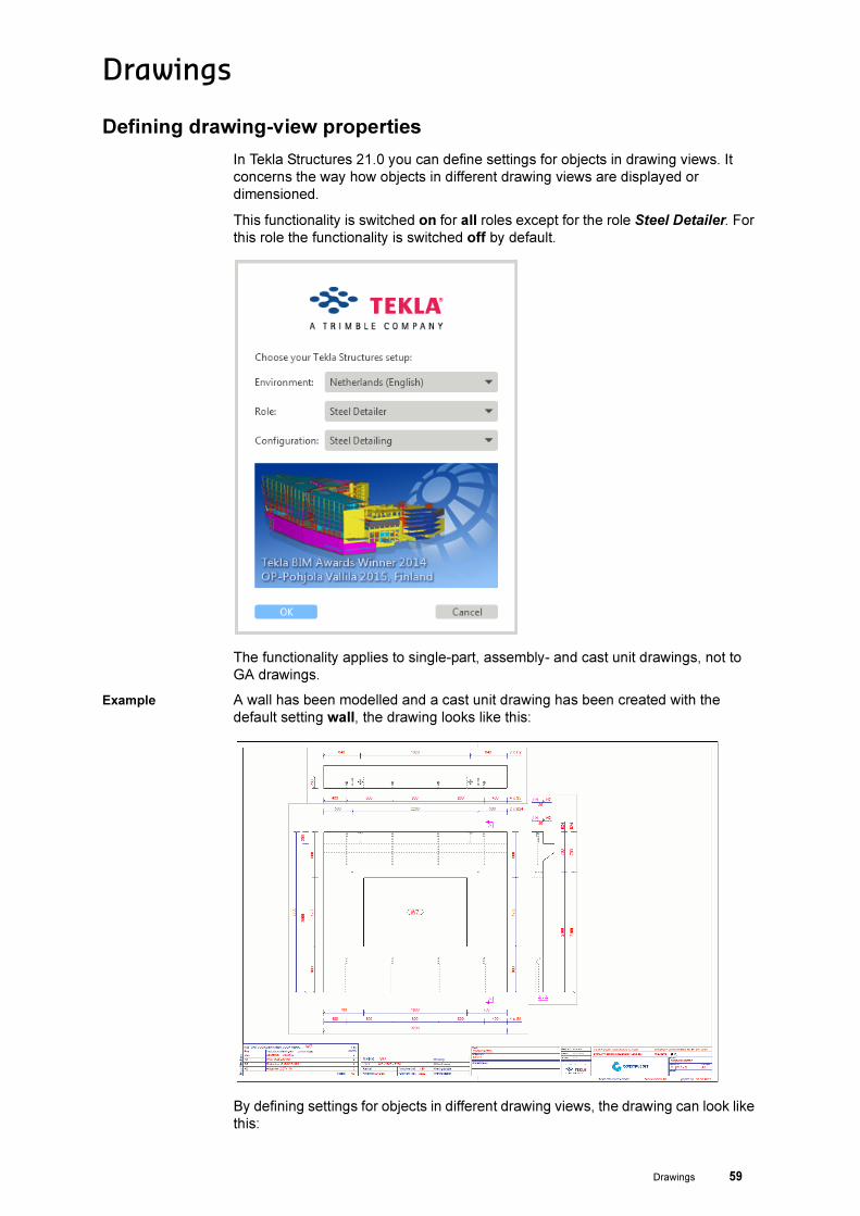
In Tekla Structures 21.0 you can define settings for objects in drawing views. It
concerns the way how objects in different drawing views are displayed or
dimensioned.
This functionality is switched on for all roles except for the role Steel Detailer. For
this role the functionality is switched off by default.
The functionality applies to single-part, assembly- and cast unit drawings, not to
GA drawings.
Example A wall has been modelled and a cast unit drawing has been created with the
default setting wall, the drawing looks like this:
By defining settings for objects in different drawing views, the drawing can look like
this:

60 Drawings
By defining settings for objects in different drawing views, you are very flexible: you
can define where you want to dimension what, so where the dimension lines are
positioned, in which order they are created/positioned and which settings you want
to use for each dimension line. The same counts for the representation of parts.
Due to this, the single-part, assembly- and cast unit drawings properties dialog
boxes have been improved and renewed to easily find and modify settings:

Drawings 61
Steel Detailer When you make use of the role Steel Detailer and you want to use this
functionality in Tekla Structures 21.0, delete the text rem in the following two
indicated lines in the file role_Steel_Detailer.ini in the folder
..:\TeklaStructures\21.0\Environments\netherlands:

62 Drawings
Improvements in the Drawing List
The Drawing List now includes the column Locked by. This option is available in
the single- and multi-user modus and in Tekla Model Sharing.
The column shows who has locked the drawing(s). If the user is logged in with his
Tekla account, this name will be showed. If not, the username by wich is logged in
on the computer, is showed.
Use the buttons Lock - On and Lock - Off to lock and unlock drawings:

Drawings 63
Information from the Drawing List in reports
Yu can now use the following new attributes to display information from the
Drawing List in reports:
• CHANGES
• LOCKED_BY
• IS_LOCKED
• IS_FROZEN
• IS_ISSUED
The attributes CHANGES and LOCKED_BY are textfields.
The attributes IS_LOCKED, IS_FROZEN and IS_ISSUED show the value 0 if
nothing is entered and the value 1 if some has entered.
In the Drawing
List
In a list

64 Drawings
Improved drawing settings for roof elements
Tekla Structures 21.0 now includes improved drawing settings for roof elements
and a corresponding wizard:
Also a number of extra assembly drawing settings available to generate the roof
element drawings per zone, including corresponding the dimensioning settings:

Drawings 65
Define units in labels
In Tekla Structures 21.0 the file MarkDimensionFormat.dim has been modified to
represent the units in millimeters by default instead of meters.
Example The toplevel of the assembly (value field ASSEMBLY_TOP_LEVEL) is added to the
mark as user-defined attribute:
66 Drawings
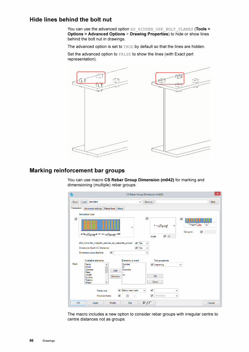
Hide lines behind the bolt nut
You can use the advanced option XS_HIDDEN_USE_BOLT_PLANES (Tools >
Options > Advanced Options > Drawing Properties) to hide or show lines
behind the bolt nut in drawings.
The advanced option is set to TRUE by default so that the lines are hidden.
Set the advanced option to FALSE to show the lines (with Exact part
representation).
Marking reinforcement bar groups
You can use macro CS Rebar Group Dimension (m042) for marking and
dimensioning (multiple) rebar groups:
The macro includes a new option to consider rebar groups with irregular centre to
centre distances not as groups:

Drawings 67
To use the macro, you first must add the macro to a new or existing toolbar in the
Model Editor in Tekla Structures via Tools > Customize:
In the Model
Editor
In the Drawing
Editor
Next, open a cast unit- or GA drawing and select the rebar group(s) to be marked.
68 Files in Tekla Structures 21.0
Files in Tekla Structures 21.0
Updating settings
As you know, you can "cut and paste" all personal settings (saved by default in the
model folder) from the model folder to the folder ts.
Because of this, your personal settings are only located in the folder ts and they
are available in all models after restarting Tekla Structures. This goes for all files
except the file dim_planes_table.txt.
During the installation of a new Tekla Structures-version, all folders except the
folder ts are updated by Construsoft. Construsoft always includes the most actual
files in these folders per version.
Our advice is not to modify these by Construsoft updated folders (such as the
folders profil and system) but only in the folder ts.
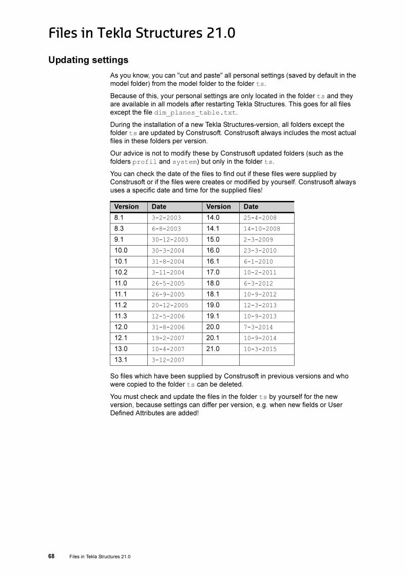
You can check the date of the files to find out if these files were supplied by
Construsoft or if the files were creates or modified by yourself. Construsoft always
uses a specific date and time for the supplied files!
So files which have been supplied by Construsoft in previous versions and who
were copied to the folder ts can be deleted.
You must check and update the files in the folder ts by yourself for the new
version, because settings can differ per version, e.g. when new fields or User
Defined Attributes are added!
Version Date Version Date
8.1 3-2-2003 14.0 25-4-2008
8.3 6-8-2003 14.1 14-10-2008
9.1 30-12-2003 15.0 2-3-2009
10.0 30-3-2004 16.0 23-3-2010
10.1 31-8-2004 16.1 6-1-2010
10.2 3-11-2004 17.0 10-2-2011
11.0 26-5-2005 18.0 6-3-2012
11.1 26-9-2005 18.1 10-9-2012
11.2 20-12-2005 19.0 12-3-2013
11.3 12-5-2006 19.1 10-9-2013
12.0 31-8-2006 20.0 7-3-2014
12.1 19-2-2007 20.1 10-9-2014
13.0 10-4-2007 21.0 10-3-2015
13.1 3-12-2007

Notities 69
Notities

70 Notities