release date : march. 2016 product ver. : civil 2016...
TRANSCRIPT

DESIGN OF CIVIL STRUCTURESI n t e g r a t e d S o l u t i o n S y s t e m f o r B r i d g e a n d C i v i l E n g i n e e r i n g
Release WebinarRelease Date : March. 2016
Product Ver. : Civil 2016 (v2.1)

Enhancements
1) Material Nonlinear Analysis available for Beam and Plate elements
2) Improvements on Moving Load Analysis
3) Triple Friction Pendulum Isolator
4) Improvement on PSC Composite Tendon property
5) Improvements on Euro Code Composite Design
6) Improvement on AASHTO Code Composite Design
7) Improvements on IRC Code Design
Analysis & Design 3
Pre & Post-Processing1) Nodal Coordinate Table in UCS
2) Improvement on Plate Local Axis
3) New Section and Material Database for Cold-formed Steel
4) Improvement on the calculation of Section Properties
5) Improvement on Soil Pressure
6) Von-Mises & Maximum Shear Stress Contour in Model View
7) Different Unit Setting for Tables and Graphs in Dynamic Report
23

Analysis & Design

4 / 35
Civil 2016 (v2.1) Release NoteCivil 2016 Analysis & Design
Stress resultant beam model is introduced to apply beam elements in the material nonlinear analysis. In cases of nonlinear stabilityanalysis for U-frame steel bridges, both beam elements and plate elements were used to represent cross beams and main girders,and previous version could not analyze this type of model
Feature availability
‒ Non-composite steel section is only supported. (Channel, I-Section, T-Section, Box, Pipe, Rectangle, Round section only.)
‒ Von Mises material property only
‒ Linear elastic / perfectly plastic (Zero hardening) stress-strain curve
‒ Plastic axial force and bending moment about minor axis only calculated
‒ Coupled effect between axial force and moment not considered
1. Material Nonlinear Analysis available for Beam elements
Material Nonlinear Analysis available for Plate elements Algorithm of material nonlinear analysis of a layer of plate element is updated from 3-dimensional condition base to plane stress
condition base. Assumption of previous algorithm had some restrain on the in-plane deformation in a layer, which stiffness of a layer was overestimated in the previous version.
Due to this change, the results of material nonlinear analysis in this version may be a bit different from the previous versionsdepending on the model.
Previous version : 3-dimensional base
2
1
1
16
2 51 1 0, 0
2
1
2
xx xx
yy yy
xy xy
zz zzxz xz
yz yz
Plate
E
, 0xx yy xy xz yz zz zz
Updated version : plane stress base
, 0, 0xx yy xy zz zz
2
1
11
1
2
xx xx
yy xx
xy xy
Plane Stress condition
E
5 / 35
Civil 2016 (v2.1) Release NoteCivil 2016 Analysis & Design
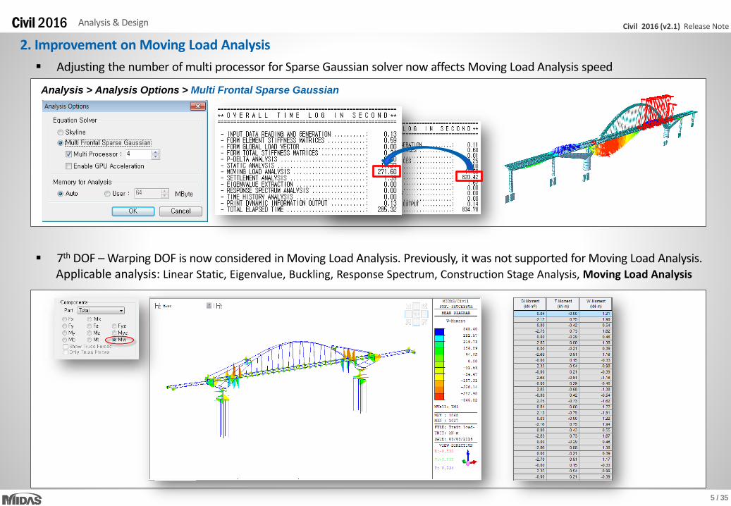
Adjusting the number of multi processor for Sparse Gaussian solver now affects Moving Load Analysis speed
2. Improvement on Moving Load Analysis
7th DOF – Warping DOF is now considered in Moving Load Analysis. Previously, it was not supported for Moving Load Analysis.Applicable analysis: Linear Static, Eigenvalue, Buckling, Response Spectrum, Construction Stage Analysis, Moving Load Analysis
Analysis > Analysis Options > Multi Frontal Sparse Gaussian
6 / 35
Civil 2016 (v2.1) Release NoteCivil 2016 Analysis & Design
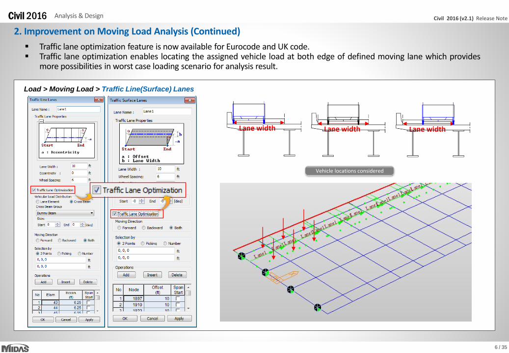
Traffic lane optimization feature is now available for Eurocode and UK code. Traffic lane optimization enables locating the assigned vehicle load at both edge of defined moving lane which provides
more possibilities in worst case loading scenario for analysis result.
2. Improvement on Moving Load Analysis (Continued)
Vehicle locations considered
Load > Moving Load > Traffic Line(Surface) Lanes

7 / 35
Civil 2016 (v2.1) Release NoteCivil 2016 Analysis & Design
3. Triple Friction Pendulum Isolator
Boundary > Link > General Link > General Link Properties
Triple Pendulum Bearing
The Triple Friction Pendulum Isolator (TFPI) is newly introduced. Correct replication of unique characteristic of TFPI in software willbroaden ouruser’sprogram application boundary and modeling ability against seismic load cases.
Here are special properties of TFPI‒ Bearing properties of three pendulums are sequentially active at different earthquake strengths‒ Stronger ground motion leads to increase in bearing displacement.
Greater bearing displacement increases effective length and damping, which reduces seismic force and total displacement.
8 / 35
Civil 2016 (v2.1) Release NoteCivil 2016 Analysis & Design
3. Triple Friction Pendulum Isolator (continued)
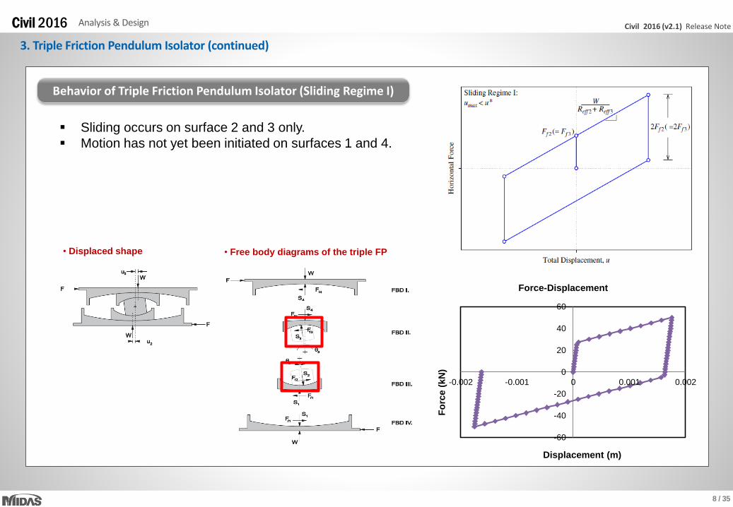
Behavior of Triple Friction Pendulum Isolator (Sliding Regime I)
• Displaced shape • Free body diagrams of the triple FP
Sliding occurs on surface 2 and 3 only.
Motion has not yet been initiated on surfaces 1 and 4.
-60
-40
-20
0
20
40
60
-0.002 -0.001 0 0.001 0.002
Fo
rce (
kN
)
Displacement (m)
Force-Displacement

9 / 35
Civil 2016 (v2.1) Release NoteCivil 2016 Analysis & Design
3. Triple Friction Pendulum Isolator (continued)
• Displaced shape • Free body diagrams of the triple FP
Sliding occurs on surface 1 and 3.
Motion has not yet been initiated on surface 4,
and there is constant displacement on surface 2.
-150
-100
-50
0
50
100
150
-0.03 -0.02 -0.01 0 0.01 0.02 0.03
Fo
rce
(k
N)
Displacement (m)
Force-Displacement
F=50 F=100
Behavior of Triple Friction Pendulum Isolator (Sliding Regime II)

10 / 35
Civil 2016 (v2.1) Release NoteCivil 2016 Analysis & Design
3. Triple Friction Pendulum Isolator (continued)
Sliding stop on surface 3 and starts on surface 4.
Sliding on surface 1 and 4.
-250
-200
-150
-100
-50
0
50
100
150
200
250
-0.12 -0.08 -0.04 0 0.04 0.08 0.12
Fo
rce (
kN
)
Displacement (m)
Force-Displacement
F=50 F=100 F=200
• Displaced shape • Free body diagrams of the triple FP
Behavior of Triple Friction Pendulum Isolator (Sliding Regime III)

11 / 35
Civil 2016 (v2.1) Release NoteCivil 2016 Analysis & Design
3. Triple Friction Pendulum Isolator (continued)
-300
-200
-100
0
100
200
300
-0.15 -0.1 -0.05 0 0.05 0.1 0.15
Fo
rce (
kN
)
Displacement (m)
Force-Displacement
F=50 F=100 F=200 F=250
The slider is on the displacement restrainer on surface 1.
Sliding occurs on surface 2 and 4, and the displacement
on surface 3 remains constant.
• Displaced shape • Free body diagrams of the triple FP
Behavior of Triple Friction Pendulum Isolator (Sliding Regime IV)

12 / 35
Civil 2016 (v2.1) Release NoteCivil 2016 Analysis & Design
3. Triple Friction Pendulum Isolator (continued)
• Displaced shape • Free body diagrams of the triple FP
-500
-400
-300
-200
-100
0
100
200
300
400
500
-0.15 -0.1 -0.05 0 0.05 0.1 0.15
Fo
rce(k
N)
Displacement (m)
Force-Displacement
F=50 F=100 F=200
The slider is on the displacement restrainer on surface 4.
Sliding occurs on surface 2 and 3, and the displacement
on surface 4 remains constant.
Behavior of Triple Friction Pendulum Isolator (Sliding Regime V)

13 / 35
Civil 2016 (v2.1) Release NoteCivil 2016 Analysis & Design
3. Triple Friction Pendulum Isolator (continued)
TFP Shear Force-Displacement history under ground acceleration
14 / 35
Civil 2016 (v2.1) Release NoteCivil 2016 Analysis & Design
3. Triple Friction Pendulum Isolator (continued)
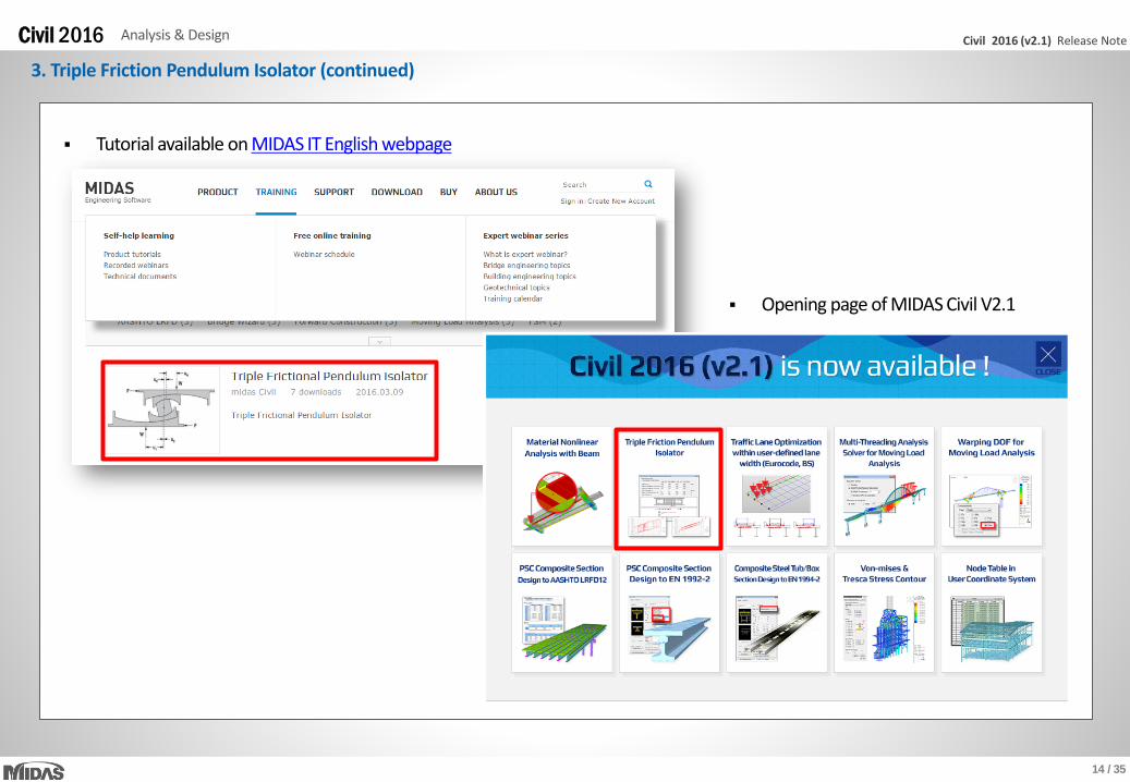
Tutorial available on MIDAS IT English webpage
Opening page of MIDAS Civil V2.1

15 / 35
Civil 2016 (v2.1) Release NoteCivil 2016 Analysis & Design
In previous definition of section property for prestressed composite girders, program automatically assumed that tendons arelocated at Part 1, girder, of Composite section, which was not always true depending on the design codes. In new version, option isadded for users to specify the part of composite section where tendon profile is passing.
If nothing is specified, program will assume that tendon profiles pass through Part 1, which is the general case for pretensionedgirders.
4. Tendon Location for Composite Section
Load > Prestress Loads > Tendon Profile > Tendon Location for Composite Section
Tendon Location for Composite Section Prestressed Composite Section

16 / 35
Civil 2016 (v2.1) Release NoteCivil 2016 Analysis & Design
5. Improvement on Euro Code Composite Design (Concrete)
PSC > Design Parameter > Eurocode 2-2:05
In previous version, only general type generated using SPC was available for design check for EN 1992-2. In new
version, Composite I, T, and PSC section properties became available. User can easily define / modify Concrete
composite sections for design check.
Applicable section type: Composite-I, Composite-T, Composite-PSC
17 / 35
Civil 2016 (v2.1) Release NoteCivil 2016 Analysis & Design
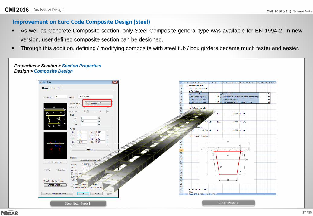
Improvement on Euro Code Composite Design (Steel)
Properties > Section > Section Properties
Design > Composite Design
As well as Concrete Composite section, only Steel Composite general type was available for EN 1994-2. In new
version, user defined composite section can be designed.
Through this addition, defining / modifying composite with steel tub / box girders became much faster and easier.
Steel Box (Type 1)
18 / 35
Civil 2016 (v2.1) Release NoteCivil 2016 Analysis & Design
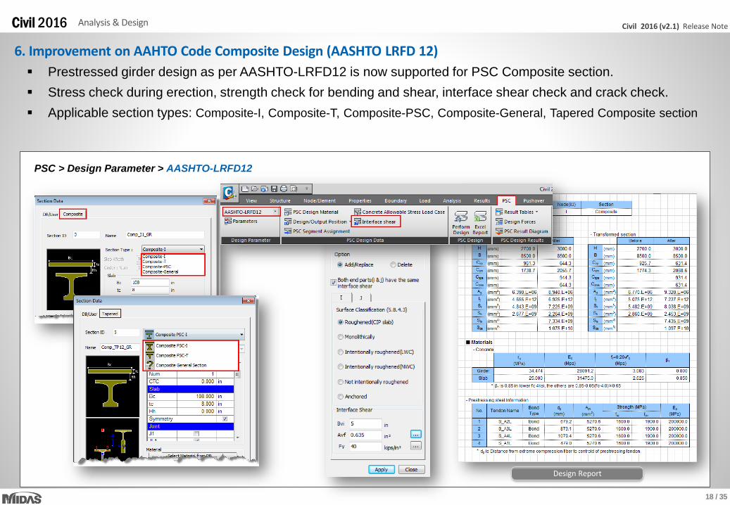
6. Improvement on AAHTO Code Composite Design (AASHTO LRFD 12)
PSC > Design Parameter > AASHTO-LRFD12
Prestressed girder design as per AASHTO-LRFD12 is now supported for PSC Composite section.
Stress check during erection, strength check for bending and shear, interface shear check and crack check.
Applicable section types: Composite-I, Composite-T, Composite-PSC, Composite-General, Tapered Composite section
Design Report
19 / 35
Civil 2016 (v2.1) Release NoteCivil 2016 Analysis & Design
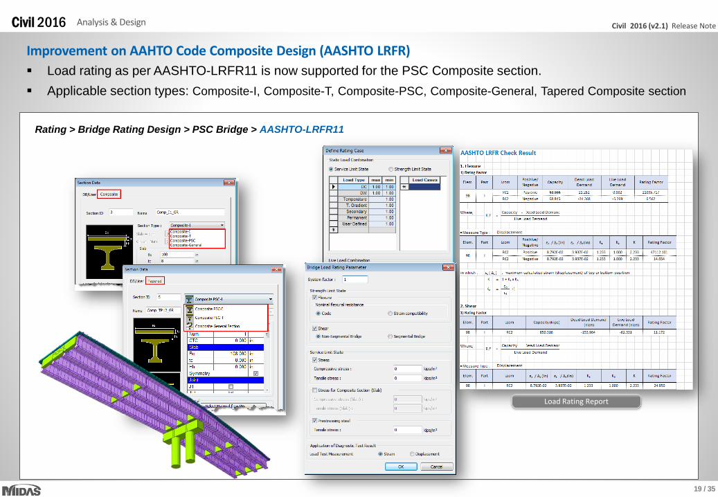
Rating > Bridge Rating Design > PSC Bridge > AASHTO-LRFR11
Load rating as per AASHTO-LRFR11 is now supported for the PSC Composite section.
Applicable section types: Composite-I, Composite-T, Composite-PSC, Composite-General, Tapered Composite section
Load Rating Report
Improvement on AAHTO Code Composite Design (AASHTO LRFR)

20 / 35
Civil 2016 (v2.1) Release NoteCivil 2016 Analysis & Design
7. Improvements on IRC Code Design (IRC 112-2012)
PSC > IRC 112-2012
PSC Composite-General section type can now be designed as per IRC 112-2012 as well as composite typical section types.
This new feature will be useful for the design of composite sections with irregular section shape.
PSC Design Parameters
SPC Composite Section Design Report

21 / 35
Civil 2016 (v2.1) Release NoteCivil 2016 Analysis & Design
PSC > RC Design > IRC 112-2011
Reinforced concrete section can now be designed as per IRC 112-2011.
Design Result Table Design Summary Report
Improvements on IRC Code Design (IRC 112-2011)
22 / 35
Civil 2016 (v2.1) Release NoteCivil 2016 Analysis & Design
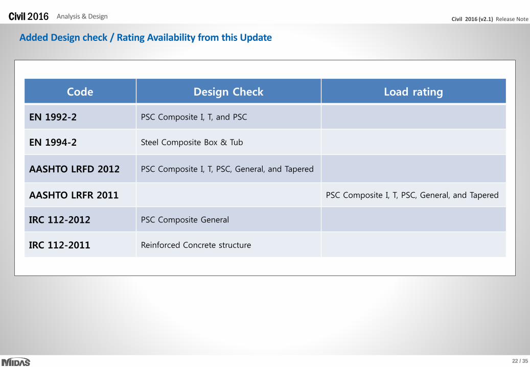
Added Design check / Rating Availability from this Update
Code Design Check Load rating
EN 1992-2 PSC Composite I, T, and PSC
EN 1994-2 Steel Composite Box & Tub
AASHTO LRFD 2012 PSC Composite I, T, PSC, General, and Tapered
AASHTO LRFR 2011 PSC Composite I, T, PSC, General, and Tapered
IRC 112-2012 PSC Composite General
IRC 112-2011 Reinforced Concrete structure

Pre & Post-Processing

24 / 35
Civil 2016 (v2.1) Release NoteCivil 2016 Pre & Post-Processing
1. Nodal Coordinate Table in UCS
Node/Element > Nodes Table
User Coordinate System for Inclined PlaneNode Table in User Coordinate System
In previous version, nodal coordinates were only available in Global Coordinate System. Starting from new version, Nodalcoordinates can be checked and modified in User Coordinate System.
Spreadsheet format node table is compatible with MS Excel to copy, paste and modify the data. The table can be insertedinto Dynamic Report.

25 / 35
Civil 2016 (v2.1) Release NoteCivil 2016 Pre & Post-Processing
In previous version, aligning plate local axis for result check was available. However, it was limited to modify once it was defined.From this update, user can Add / Replace or Delete aligned local axis of plate elements.
This function is useful for unstructured meshes or cylindrical structure.
2. Improvement on Plate Local Axis
Results > Detail > Plate Local Axis
Plate Local Axis Plate Local Axis for Round Shape Slab

26 / 35
Civil 2016 (v2.1) Release NoteCivil 2016 Pre & Post-Processing
3. New Section and Material Database for Cold-formed Steel Cold-formed Channel, Pipe, Box and Upright section DB as per UNI (Italian standard) and SS (Singaporean Standard) has
been newly implemented.
Steel section DB as per ICHA (Chilean standard) has been added for Angle, Double Angle, Star Battened Angle, I-shape,Channel, Double Channel and Lipped channel.
Cold-formed material DB as per EN10326, EN 10149-2 and EN 10149-3 has been newly implemented.
Properties > Section Properties
Properties > Material Properties
UNI Upright Section SS Cold Formed Channel ICHA Double Angle
27 / 35
Civil 2016 (v2.1) Release NoteCivil 2016 Pre & Post-Processing
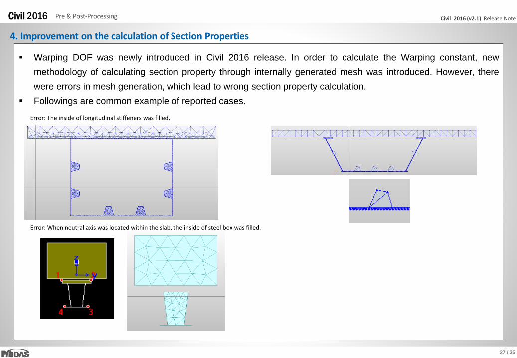
4. Improvement on the calculation of Section Properties
Error: The inside of longitudinal stiffeners was filled.
Error: When neutral axis was located within the slab, the inside of steel box was filled.
Warping DOF was newly introduced in Civil 2016 release. In order to calculate the Warping constant, new
methodology of calculating section property through internally generated mesh was introduced. However, there
were errors in mesh generation, which lead to wrong section property calculation.
Followings are common example of reported cases.
28 / 35
Civil 2016 (v2.1) Release NoteCivil 2016 Pre & Post-Processing
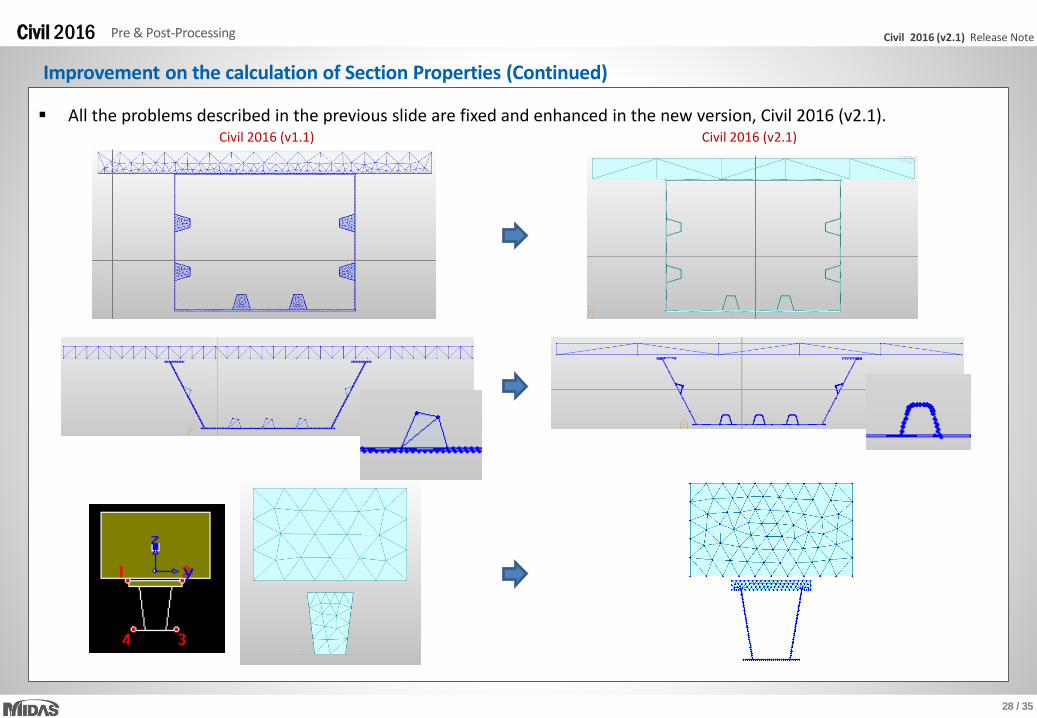
Improvement on the calculation of Section Properties (Continued)
All the problems described in the previous slide are fixed and enhanced in the new version, Civil 2016 (v2.1).Civil 2016 (v1.1) Civil 2016 (v2.1)

29 / 35
Civil 2016 (v2.1) Release NoteCivil 2016 Pre & Post-Processing
Improvement on the calculation of Section Properties (Continued)
Also, mesh quality is improved in the new version, Civil 2016 (v2.1), which will increase the accuracy of shear area.
Civil 2016 (v1.1) Civil 2016 (v2.1)

30 / 35
Civil 2016 (v2.1) Release NoteCivil 2016 Pre & Post-Processing
Improvement on the calculation of Section Properties (Continued)
• Test model 1
– Steel Composite Girder Bridge
– Tapered Section Group
– 1901 elements
Running time Improvement
Civil 2016 (v1.1) 2 hours
Civil 2016 (v2.1) 1 min. 16 sec. 95 times faster
• Comparison
Model running time is much reduced in the new version, Civil 2016 (v2.1).
• Test model 2
– Steel Composite Girder Bridge
– Tapered Section Group
– 4281 elements
Running time Improvement
Civil 2016 (v1.1) 1 hour 19 min.
Civil 2016 (v2.1) 46 sec. 103 times faster
• Comparison
31 / 35
Civil 2016 (v2.1) Release NoteCivil 2016 Pre & Post-Processing
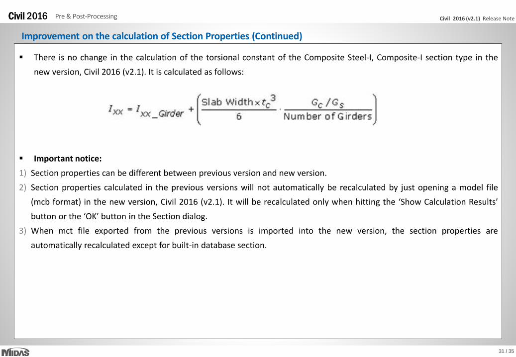
Improvement on the calculation of Section Properties (Continued)
There is no change in the calculation of the torsional constant of the Composite Steel-I, Composite-I section type in the
new version, Civil 2016 (v2.1). It is calculated as follows:
Important notice:
1) Section properties can be different between previous version and new version.
2) Section properties calculated in the previous versions will not automatically be recalculated by just opening a model file
(mcb format) in the new version, Civil 2016 (v2.1). It will be recalculated only when hitting the ‘Show Calculation Results’
button or the ‘OK’ button in the Section dialog.
3) When mct file exported from the previous versions is imported into the new version, the section properties are
automatically recalculated except for built-in database section.

32 / 35
Civil 2016 (v2.1) Release NoteCivil 2016 Pre & Post-Processing
5. Improvement on Soil Pressure
Results > Reactions > Soil Pressure
Soil Pressure Soil Pressure Contour
Surface Spring Support Table
Point Spring Support Table
Soil pressure contours were provided on the beam, plate or solid elements representing subgrade beam, mat foundation orretaining wall. In the new version, following improvements have been made:
For inclined foundation,projection area is accurately calculated Incorrectly calculated soil pressures at nodes where horizontal and vertical springs were simultaneously applied are now correctly calculated and saved
separately.Effective area to calculate soil pressurewas initialized as zero when soil stiffness was modified in Point Spring Support Table. It is now corrected.Modulus of Subgradevalues can be checked and modified in Surface Spring Support table for compression-only type springs.

33 / 35
Civil 2016 (v2.1) Release NoteCivil 2016 Pre & Post-Processing
In previous version, Von-Mises or Tresca stress result was only available in Beam Detail Analysis per element.In new version, equivalent stress distribution enabled reviewing stress contour of entire model.
Available section types and considered stress points are displayed in ‘Guide’ Option.
Result > Stresses > Beam Stresses (Equivalent)
Beam Stresses (Equivalent) Contour and Table
Main Control Data
Applicable Section Shape and Stress Points
6. Von-Mises & Maximum Shear Stress Contour in Model View
34 / 35
Civil 2016 (v2.1) Release NoteCivil 2016 Pre & Post-Processing
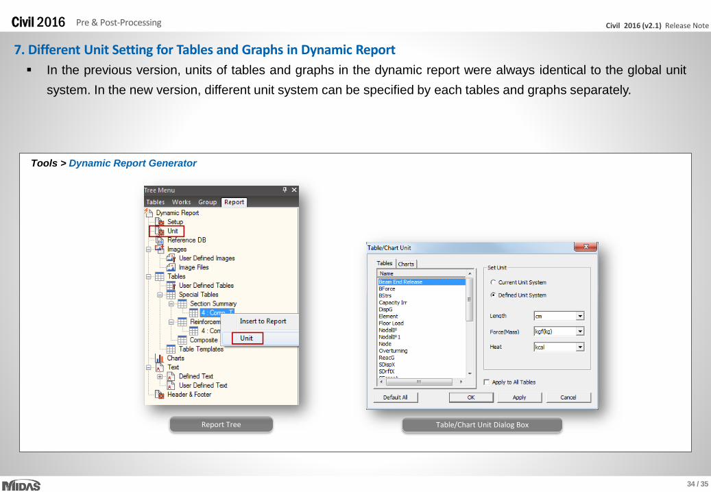
Report Tree
7. Different Unit Setting for Tables and Graphs in Dynamic Report
Tools > Dynamic Report Generator
In the previous version, units of tables and graphs in the dynamic report were always identical to the global unit
system. In the new version, different unit system can be specified by each tables and graphs separately.
Table/Chart Unit Dialog Box

Thank you