relay - the mechanicthemechanic.weebly.com/uploads/4/3/5/7/4357357/relay.pdf · other operating...
TRANSCRIPT

Relay 1
Relay
Automotive-style miniature relay, dust cover istaken off
A relay is an electrically operated switch. Many relays use anelectromagnet to operate a switching mechanism mechanically, butother operating principles are also used. Relays are used where it isnecessary to control a circuit by a low-power signal (with completeelectrical isolation between control and controlled circuits), or whereseveral circuits must be controlled by one signal. The first relays wereused in long distance telegraph circuits, repeating the signal coming infrom one circuit and re-transmitting it to another. Relays were usedextensively in telephone exchanges and early computers to performlogical operations.
A type of relay that can handle the high power required to directlydrive an electric motor is called a contactor. Solid-state relays controlpower circuits with no moving parts, instead using a semiconductordevice to perform switching. Relays with calibrated operatingcharacteristics and sometimes multiple operating coils are used toprotect electrical circuits from overload or faults; in modern electricpower systems these functions are performed by digital instrumentsstill called "protective relays".
Basic design and operation
Simple electromechanical relay
A simple electromagnetic relay consists of a coil of wire surrounding asoft iron core, an iron yoke which provides a low reluctance path formagnetic flux, a movable iron armature, and one or more sets ofcontacts (there are two in the relay pictured). The armature is hinged tothe yoke and mechanically linked to one or more sets of movingcontacts. It is held in place by a spring so that when the relay isde-energized there is an air gap in the magnetic circuit. In thiscondition, one of the two sets of contacts in the relay pictured is closed,and the other set is open. Other relays may have more or fewer sets ofcontacts depending on their function. The relay in the picture also has awire connecting the armature to the yoke. This ensures continuity of the circuit between the moving contacts on thearmature, and the circuit track on the printed circuit board (PCB) via the yoke, which is soldered to the PCB.
When an electric current is passed through the coil it generates a magnetic field that attracts the armature, and theconsequent movement of the movable contact(s) either makes or breaks (depending upon construction) a connectionwith a fixed contact. If the set of contacts was closed when the relay was de-energized, then the movement opens thecontacts and breaks the connection, and vice versa if the contacts were open. When the current to the coil is switchedoff, the armature is

Relay 2
Small relay as used in electronics
returned by a force, approximately half as strong as the magnetic force,to its relaxed position. Usually this force is provided by a spring, butgravity is also used commonly in industrial motor starters. Most relaysare manufactured to operate quickly. In a low-voltage application thisreduces noise; in a high voltage or current application it reduces arcing.
When the coil is energized with direct current, a diode is often placed across the coil to dissipate the energy from thecollapsing magnetic field at deactivation, which would otherwise generate a voltage spike dangerous tosemiconductor circuit components. Some automotive relays include a diode inside the relay case. Alternatively, acontact protection network consisting of a capacitor and resistor in series (snubber circuit) may absorb the surge. Ifthe coil is designed to be energized with alternating current (AC), a small copper "shading ring" can be crimped tothe end of the solenoid, creating a small out-of-phase current which increases the minimum pull on the armatureduring the AC cycle.[1]
A solid-state relay uses a thyristor or other solid-state switching device, activated by the control signal, to switch thecontrolled load, instead of a solenoid. An optocoupler (a light-emitting diode (LED) coupled with a photo transistor)can be used to isolate control and controlled circuits.
Types
Latching relay
Latching relay, dust cover removed, showingpawl and ratchet mechanism. The ratchet operates
a cam, which raises and lowers the movingcontact arm, seen edge-on just below it. The
moving and fixed contacts are visible at the leftside of the image.
A latching relay has two relaxed states (bistable). These are also called"impulse", "keep", or "stay" relays. When the current is switched off,the relay remains in its last state. This is achieved with a solenoidoperating a ratchet and cam mechanism, or by having two opposingcoils with an over-center spring or permanent magnet to hold thearmature and contacts in position while the coil is relaxed, or with aremanent core. In the ratchet and cam example, the first pulse to thecoil turns the relay on and the second pulse turns it off. In the two coilexample, a pulse to one coil turns the relay on and a pulse to theopposite coil turns the relay off. This type of relay has the advantagethat it consumes power only for an instant, while it is being switched,and it retains its last setting across a power outage. A remanent corelatching relay requires a current pulse of opposite polarity to make itchange state.

Relay 3
Reed relayA reed relay is a reed switch enclosed in a solenoid. The switch has a set of contacts inside an evacuated or inertgas-filled glass tube which protects the contacts against atmospheric corrosion; the contacts are made of magneticmaterial that makes them move under the influence of the field of the enclosing solenoid. Reed relays can switchfaster than larger relays, require only little power from the control circuit, but have low switching current and voltageratings.
Top, middle: reed switches, bottom: reed relay
Mercury-wetted relay
A mercury-wetted reed relay is a form of reed relay in which thecontacts are wetted with mercury. Such relays are used to switchlow-voltage signals (one volt or less) where the mercury reduces thecontact resistance and associated voltage drop, for low-current signalswhere surface contamination may make for a poor contact, or forhigh-speed applications where the mercury eliminates contact bounce.Mercury wetted relays are position-sensitive and must be mountedvertically to work properly. Because of the toxicity and expense ofliquid mercury, these relays are now rarely used. See also mercury switch.
Polarized relayA polarized relay placed the armature between the poles of a permanent magnet to increase sensitivity. Polarizedrelays were used in middle 20th Century telephone exchanges to detect faint pulses and correct telegraphicdistortion. The poles were on screws, so a technician could first adjust them for maximum sensitivity and then applya bias spring to set the critical current that would operate the relay.
Machine tool relayA machine tool relay is a type standardized for industrial control of machine tools, transfer machines, and othersequential control. They are characterized by a large number of contacts (sometimes extendable in the field) whichare easily converted from normally-open to normally-closed status, easily replaceable coils, and a form factor thatallows compactly installing many relays in a control panel. Although such relays once were the backbone ofautomation in such industries as automobile assembly, the programmable logic controller (PLC) mostly displaced themachine tool relay from sequential control applications.
Contactor relayA contactor is a very heavy-duty relay used for switching electric motors and lighting loads, although contactors arenot generally called relays. Continuous current ratings for common contactors range from 10 amps to severalhundred amps. High-current contacts are made with alloys containing silver. The unavoidable arcing causes thecontacts to oxidize; however, silver oxide is still a good conductor.[2] Such devices are often used for motor starters.A motor starter is a contactor with overload protection devices attached. The overload sensing devices are a form ofheat operated relay where a coil heats a bi-metal strip, or where a solder pot melts, releasing a spring to operateauxiliary contacts. These auxiliary contacts are in series with the coil. If the overload senses excess current in theload, the coil is de-energized. Contactor relays can be extremely loud to operate, making them unfit for use wherenoise is a chief concern.

Relay 4
Solid-state relay
Solid state relay, which has no moving parts
25 A or 40 A solid state contactors
A solid state relay (SSR) is a solid state electronic component thatprovides a similar function to an electromechanical relay but does nothave any moving components, increasing long-term reliability. Withearly SSR's, the tradeoff came from the fact that every transistor has asmall voltage drop across it. This voltage drop limited the amount ofcurrent a given SSR could handle. As transistors improved, highercurrent SSR's, able to handle 100 to 1,200 Amperes, have becomecommercially available. Compared to electromagnetic relays, they maybe falsely triggered by transients.
Solid state contactor relay
A solid state contactor is a heavy-duty solid state relay, including thenecessary heat sink, used for switching electric heaters, small electricmotors and lighting loads; where frequent on/off cycles are required.There are no moving parts to wear out and there is no contact bouncedue to vibration. They are activated by AC control signals or DCcontrol signals from Programmable logic controller (PLCs), PCs,Transistor-transistor logic (TTL) sources, or other microprocessor andmicrocontroller controls.
Buchholz relay
A Buchholz relay is a safety device sensing the accumulation of gas inlarge oil-filled transformers, which will alarm on slow accumulation of gas or shut down the transformer if gas isproduced rapidly in the transformer oil.
Forced-guided contacts relayA forced-guided contacts relay has relay contacts that are mechanically linked together, so that when the relay coilis energized or de-energized, all of the linked contacts move together. If one set of contacts in the relay becomesimmobilized, no other contact of the same relay will be able to move. The function of forced-guided contacts is toenable the safety circuit to check the status of the relay. Forced-guided contacts are also known as "positive-guidedcontacts", "captive contacts", "locked contacts", or "safety relays".
Overload protection relayElectric motors need overcurrent protection to prevent damage from over-loading the motor, or to protect againstshort circuits in connecting cables or internal faults in the motor windings.[3] One type of electric motor overloadprotection relay is operated by a heating element in series with the electric motor. The heat generated by the motorcurrent heats a bimetallic strip or melts solder, releasing a spring to operate contacts. Where the overload relay isexposed to the same environment as the motor, a useful though crude compensation for motor ambient temperatureis provided.

Relay 5
Pole and throw
Circuit symbols of relays. (C denotes the commonterminal in SPDT and DPDT types.)
Since relays are switches, the terminology applied to switches isalso applied to relays. A relay will switch one or more poles, eachof whose contacts can be thrown by energizing the coil in one ofthree ways:
• Normally-open (NO) contacts connect the circuit when therelay is activated; the circuit is disconnected when the relay isinactive. It is also called a Form A contact or "make" contact.
• Normally-closed (NC) contacts disconnect the circuit when therelay is activated; the circuit is connected when the relay isinactive. It is also called a Form B contact or "break" contact.
• Change-over (CO), or double-throw (DT), contacts control twocircuits: one normally-open contact and one normally-closedcontact with a common terminal. It is also called a Form Ccontact or "transfer" contact ("break before make"). If this typeof contact utilizes a "make before break" functionality, then it iscalled a Form D contact.
The following designations are commonly encountered:• SPST – Single Pole Single Throw. These have two terminals
which can be connected or disconnected. Including two for thecoil, such a relay has four terminals in total. It is ambiguouswhether the pole is normally open or normally closed. The terminology "SPNO" and "SPNC" is sometimes usedto resolve the ambiguity.
• SPDT – Single Pole Double Throw. A common terminal connects to either of two others. Including two for thecoil, such a relay has five terminals in total.
• DPST – Double Pole Single Throw. These have two pairs of terminals. Equivalent to two SPST switches orrelays actuated by a single coil. Including two for the coil, such a relay has six terminals in total. The poles maybe Form A or Form B (or one of each).
• DPDT – Double Pole Double Throw. These have two rows of change-over terminals. Equivalent to two SPDTswitches or relays actuated by a single coil. Such a relay has eight terminals, including the coil.
The "S" or "D" may be replaced with a number, indicating multiple switches connected to a single actuator. Forexample 4PDT indicates a four pole double throw relay (with 14 terminals).EN 50005 are among applicable standards for relay terminal numbering; a typical EN 50005-compliant SPDT relay'sterminals would be numbered 11, 12, 14, A1 and A2 for the C, NC, NO, and coil connections, respectively.
ApplicationsRelays are used to and for:• Control a high-voltage circuit with a low-voltage signal, as in some types of modems or audio amplifiers,• Control a high-current circuit with a low-current signal, as in the starter solenoid of an automobile,• Detect and isolate faults on transmission and distribution lines by opening and closing circuit breakers (protection
relays),

Relay 6
A DPDT AC coil relay with "ice cube"packaging
• Isolate the controlling circuit from the controlled circuit when the two areat different potentials, for example when controlling a mains-powereddevice from a low-voltage switch. The latter is often applied to controloffice lighting as the low voltage wires are easily installed in partitions,which may be often moved as needs change. They may also be controlledby room occupancy detectors in an effort to conserve energy,
• Logic functions. For example, the boolean AND function is realised byconnecting normally open relay contacts in series, the OR function byconnecting normally open contacts in parallel. The change-over or Form Ccontacts perform the XOR (exclusive or) function. Similar functions forNAND and NOR are accomplished using normally closed contacts. TheLadder programming language is often used for designing relay logicnetworks.
• Early computing. Before vacuum tubes and transistors, relays were usedas logical elements in digital computers. See ARRA (computer), Harvard Mark II, Zuse Z2, and Zuse Z3.
• Safety-critical logic. Because relays are much more resistant than semiconductors to nuclear radiation, they arewidely used in safety-critical logic, such as the control panels of radioactive waste-handling machinery.
• Time delay functions. Relays can be modified to delay opening or delay closing a set of contacts. A very short (afraction of a second) delay would use a copper disk between the armature and moving blade assembly. Currentflowing in the disk maintains magnetic field for a short time, lengthening release time. For a slightly longer (up toa minute) delay, a dashpot is used. A dashpot is a piston filled with fluid that is allowed to escape slowly. Thetime period can be varied by increasing or decreasing the flow rate. For longer time periods, a mechanicalclockwork timer is installed.
Relay application considerations
A large relay with two coils and many sets ofcontacts, used in an old telephone switching
system.
Selection of an appropriate relay for a particular application requiresevaluation of many different factors:• Number and type of contacts – normally open, normally closed,
(double-throw)• Contact sequence – "Make before Break" or "Break before Make".
For example, the old style telephone exchanges requiredMake-before-break so that the connection didn't get dropped whiledialling the number.
• Rating of contacts – small relays switch a few amperes, largecontactors are rated for up to 3000 amperes, alternating or directcurrent
• Voltage rating of contacts – typical control relays rated 300 VAC or600 VAC, automotive types to 50 VDC, special high-voltage relaysto about 15 000 V
• Coil voltage – machine-tool relays usually 24 VAC, 120 or 250 VAC, relays for switchgear may have 125 V or250 VDC coils, "sensitive" relays operate on a few milliamperes
• Coil current
Relay 7
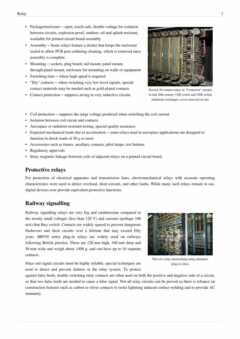
Several 30-contact relays in "Connector" circuitsin mid 20th century 1XB switch and 5XB switch
telephone exchanges; cover removed on one
• Package/enclosure – open, touch-safe, double-voltage for isolationbetween circuits, explosion proof, outdoor, oil and splash resistant,washable for printed circuit board assembly
• Assembly – Some relays feature a sticker that keeps the enclosuresealed to allow PCB post soldering cleaning, which is removed onceassembly is complete.
• Mounting – sockets, plug board, rail mount, panel mount,through-panel mount, enclosure for mounting on walls or equipment
• Switching time – where high speed is required• "Dry" contacts – when switching very low level signals, special
contact materials may be needed such as gold-plated contacts• Contact protection – suppress arcing in very inductive circuits
• Coil protection – suppress the surge voltage produced when switching the coil current• Isolation between coil circuit and contacts• Aerospace or radiation-resistant testing, special quality assurance• Expected mechanical loads due to acceleration – some relays used in aerospace applications are designed to
function in shock loads of 50 g or more• Accessories such as timers, auxiliary contacts, pilot lamps, test buttons• Regulatory approvals• Stray magnetic linkage between coils of adjacent relays on a printed circuit board.
Protective relaysFor protection of electrical apparatus and transmission lines, electromechanical relays with accurate operatingcharacteristics were used to detect overload, short-circuits, and other faults. While many such relays remain in use,digital devices now provide equivalent protective functions.
Railway signalling
Part of a relay interlocking using miniatureplug-in relays
Railway signalling relays are very big and cumbersome compared tothe mostly small voltages (less than 120 V) and currents (perhaps 100mA) that they switch. Contacts are widely spaced to prevent dangerousflashovers and short circuits over a lifetime that may exceed fiftyyears. BR930 series plug-in relays are widely used on railwaysfollowing British practice. These are 120 mm high, 180 mm deep and56 mm wide and weigh about 1400 g, and can have up to 16 separatecontacts.
Since rail signal circuits must be highly reliable, special techniques areused to detect and prevent failures in the relay system. To protectagainst false feeds, double switching relay contacts are often used on both the positive and negative side of a circuit,so that two false feeds are needed to cause a false signal. Not all relay circuits can be proved so there is reliance onconstruction features such as carbon to silver contacts to resist lightning induced contact welding and to provide ACimmunity.

Relay 8
UK Q-style signalling relay and base
See also
• Contactor• Digital protective relay
• Dry contact• Race condition• Wire spring relay
References[1] Mason, C. R., Art & Science of Protective Relaying, Chapter 2, GE Consumer & Electrical (http:/ / www. geindustrial. com/ Multilin/ notes/
artsci/ index. htm)[2] Kenneth B. Rexford and Peter R. Giuliani (2002). Electrical control for machines (http:/ / books. google. com/ books?id=5RkbwbYq1joC&
pg=PA58& lpg=PA58& dq=silver-oxide+ relay+ contact& source=bl& ots=P4QvEFgf8M& sig=XcF_4ed6DvucJvwck6Q4fxIKjEM&hl=en& ei=8yHlSqH5H4SsswOM6rmwBA& sa=X& oi=book_result& ct=result& resnum=2& ved=0CBAQ6AEwAQ#v=onepage&q=silver-oxide relay contact& f=false) (6th ed.). Cengage Learning. p. 58. ISBN 9780766861985. .
[3] Zocholl, Stan (2003). AC Motor Protection. Schweitzer Engineering Laboratories, Inc.. ISBN 0972502610, 978-0972502610.
• Gurevich, Vladimir (2005). Electrical Relays: Principles and Applications. London - New York: CRC Press.• Westinghouse Corporation (1976). Applied Protective Relaying. Westinghouse Corporation. Library of Congress
card no. 76-8060.• Terrell Croft and Wilford Summers (ed) (1987). American Electricians' Handbook, Eleventh Edition. New York:
McGraw Hill. ISBN 0-07-013932-6.• Walter A. Elmore. Protective Relaying Theory and Applications. Marcel Dekker, Inc.. ISBN 0-8247-9152-5.• Vladimir Gurevich (2008). Electronic Devices on Discrete Components for Industrial and Power Engineering.
London - New York: CRC Press. pp. 418.• Vladimir Gurevich (2003). Protection Devices and Systems for High-Voltage Applications. London - New York:
CRC Press. pp. 292.
External links• Information about relays and the Latching Relay circuit (http:/ / www. eleinmec. com/ article. asp?24)• "Harry Porter's Relay Computer", a computer made out of relays. (http:/ / web. cecs. pdx. edu/ ~harry/ Relay/
index. html)• "Relay Computer Two", by Jon Stanley. (http:/ / www. electronixandmore. com/ project/ relaycomputertwo/
index. html)• Interfacing Relay To Microcontroller. (http:/ / www. dnatechindia. com/ index. php/ Tutorials/ 8051-Tutorial/
Relay-Interfacing. html)• A Relay General Application Guidelines (http:/ / www. tai-shing. com. tw/ technical/ relay. htm)