relay loadability challenges … loadability...relay loadability challenges experienced in long...
TRANSCRIPT

RELAY LOADABILITY CHALLENGES EXPERIENCED IN LONG LINES
Authors:
Seunghwa Lee P.E., SynchroGrid, College Station, Texas 77845
Joe Perez P.E., SynchroGrid, College Station, Texas 77802
Presented before the 69th Annual
Texas A&M Protective Relay Conference College Station, Texas
April 4th – April 7th, 2016

RELAY LOADABILITY CHALLENGES IN LONG LINES
Seunghwa Lee P.E., SynchroGrid, College Station, Texas, [email protected] Joe Perez P.E., SynchroGrid, College Station, Texas, [email protected]
I. Introduction Ever since the blackout in the Northeast in 2003, a variety of relay setting methods have been employed with the express purpose of avoiding unnecessary trips caused by power swings and overloads. Protection engineers have used the load encroachment and out-of-step functions to mitigate the overload and swing events. The updated NERC PRC-023-3 R1 states that transmission line relays cannot operate at or below 150% of the highest seasonal facility rating of a circuit. Additionally, R2 states that out-of-step blocking elements should allow tripping of phase protective relays for faults that occur during the loading conditions used to verify transmission line relay loadability per requirement R1. Many microprocessor relays installed today use inner and outer blinders for out-of-step functions. When the standard is applied to very long lines, the loadability point can be located inside Zone 1. If the load is high enough that it encroaches into Zone 1, the out-of-step function will no longer work since the inner and outer blinder will be located outside Zone 2. This paper presents the problems and their solutions to the NERC loadability requirements experienced in long lines. In addition, this paper will provide the derivatives of load encroachment calculations using the mho circle and simulations for an overall better understanding.
II. NERC PRC-023-3 This section presents information and justification for NERC PRC-023-3 Transmission Relay Loadability which show standards regarding loadability setting and out-of-step setting. Transmission relay loadability verification was performed for requirement R1, criteria 1 and 4 and requirement R2. R1verifies the maximum loadability setting and R2 verifies the out-of-step requirement of the standard. Requirement R1.1 and R1.4 Compliance Definitions R1. Each Transmission Owner, Generator Owner, and Distribution Provider shall use any one of the following criteria (Requirement R1, criteria 1 through 13) for any specific circuit terminal to prevent its phase protective relay settings from limiting transmission system loadability while maintaining reliable protection of the BES for all fault conditions. Each Transmission Owner, Generator Owner, and Distribution Provider shall evaluate relay loadability at 0.85 per unit voltage and a power factor angle of 30 degrees. Criteria: R1.1 Set transmission line relays so they do not operate at or below 150% of the highest seasonal Facility Rating of a circuit, for the available defined loading duration nearest 4 hours (expressed in amperes).
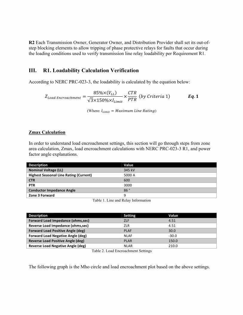
R2 Each Transmission Owner, Generator Owner, and Distribution Provider shall set its out-of-step blocking elements to allow tripping of phase protective relays for faults that occur during the loading conditions used to verify transmission line relay loadability per Requirement R1. III. R1. Loadability Calculation Verification According to NERC PRC-023-3, the loadability is calculated by the equation below:
𝑍"#$%'()*#$)+,-(. =85%× 𝑉""3×150%×𝐼"9,9.
×𝐶𝑇𝑅𝑃𝑇𝑅 𝑏𝑦𝐶𝑟𝑖𝑡𝑒𝑟𝑖𝑎1 𝑬𝒒. 𝟏
(Where: 𝐼"9,9. = 𝑀𝑎𝑥𝑖𝑚𝑢𝑚𝐿𝑖𝑛𝑒𝑅𝑎𝑡𝑖𝑛𝑔)
Zmax Calculation In order to understand load encroachment settings, this section will go through steps from zone area calculation, Zmax, load encroachment calculations with NERC PRC-023-3 R1, and power factor angle explanations. Description ValueNominalVoltage(LL) 345kVHighestSeasonalLineRating(Current) 5000ACTR 600PTR 3000ConductorImpedanceAngle 86°Zone3Forward 9
Table 1. Line and Relay Information Description Setting ValueForwardLoadImpedance(ohms,sec) ZLF 4.51ReverseLoadImpedance(ohms,sec) ZLR 4.51ForwardLoadPositiveAngle(deg) PLAF 30.0ForwardLoadNegativeAngle(deg) NLAF -30.0ReverseLoadPositiveAngle(deg) PLAR 150.0ReverseLoadNegativeAngle(deg) NLAR 210.0
Table 2. Load Encroachment Settings The following graph is the Mho circle and load encroachment plot based on the above settings.

Figure 1. Load Encroachment and mho circle plot
Z3F is used in this example but this can be applied to any zone. NERC PRC-023-3 R1 says “Each Transmission Owner, Generator Owner, and Distribution Provider shall evaluate relay loadability at 0.85 per unit voltage and a power factor angle of 30 degrees”. The relay loadability is done to check whether Z3F trips under maximum load conditions. For this, Zmax should be calculated, which is the maximum reach that Z3F needs to be set to before it trips under load conditions. In other words, Zmax is the impendence based on the conductor current limit and it is necessary for Z3F settings when the load encroachment is not used. If load encroachment settings do not exist, Z3F will be set to Zmax. The magnitude of Zmax is calculated below:
𝑍,$P =85%×𝑉""
3×150%×𝐼Q9,9.#R)#(%S).#*×𝑐𝑜𝑠𝑎×𝐶𝑇𝑅𝑃𝑇𝑅 𝑬𝒒. 𝟐
=0.85×345𝑘𝑉
3×150%×5000𝐴× 𝑐𝑜𝑠 86° − 30°×6003000
= 8.07
Relationship Between Zmax and Zload The equation above uses 85% of nominal voltage recommendation and power factor angle. Zmax has the same angle as the protected line impedance angle. Therefore, Zmax vector is 𝑍,$P =8.07∠86°. The reason the margins of 85% and 150 % exist in the above equations is due to the NERC standard Criteria 1. Notice that Z3F will trip during maximum load conditions. Therefore, Z3F has to be set to Zmax in this given example case.

Figure 2. Zone 3 forward and Zmax
The power factor that was mentioned in NERC standard does not have to be considered when we calculate ZLF and ZLR because the equation is only to get the magnitude of the load. The angle is manually set to PLAF, NLAF, PLAR and NLAR. In this example, the power factor is set to 30 degrees, which complies with the NERC standard. Load Encroachment (Zload) Calculation The above procedure has helped us to determine the maximum loadability reach, but we also need to evaluate it from the point of view of the power factor angle of 30 degrees. This is done by calculating the load encroachment vector and Zload. Load encroachment setting can be easily calculated if we know Zmax value as follows:
𝑍Q#$% = 𝑍,$P × 𝑐𝑜𝑠 𝑎 𝑬𝒒. 𝟑 In order to track how the power factor was applied, it is necessary to understand the relationship between Zload and Zmax. Zmax is the maximum impedance of the line conductor, based on the line rating of the conductor. This impedance also has the same angle as the conductor impedance, 86 degrees. Zload is load impedance based on line rating, however this has a different angle from the line conductor. The angle was given as 30 degrees in this example. The angle between Zmax and Zload is 𝒂 = (86° − 30°) as shown below.
𝑍,$Pddddddddddd⃗ = 8.07∠86°
𝑍3𝐹dddddddd⃗ = 9∠86°

a30
Figure 3. Relationship between Zmax and Zload
According to Eq.2, 𝑍,$P = 8.07∠86°. By using trigonometry, the Zload vector can be calculated:
𝑐𝑜𝑠 𝑎 =𝑍Q#$%𝑍,$P
𝑍Q#$% = 𝑍,$P × cos 𝑎 (Power factor is applied here)
𝑍Q#$% = 8.07× 𝑐𝑜𝑠 86° − 30° = 4.51
∴ 𝑍Q#$% = 4.51∠30°
𝑍Q#$% =85%×𝑉""
3×150%×𝐼Q9,9.#R)#(%S).#*×𝐶𝑇𝑅𝑃𝑇𝑅
=0.85×345𝑘𝑉3×150%×5000𝐴
×6003000
= 4.51𝑂ℎ𝑚𝑠
The same result will be shown as when the angle was considered. It can be proven no matter what angle is chosen because the magnitude of Zload is the same. This is why we use the load encroachment setting to calculate the maximum MVA. ZLF and ZLR indicate the magnitude of load encroachment. This magnitude is set to 85% of the minimum load impedance based on 150% of the line limit based on NERC PRC-023-3, as
𝑍,$Pddddddddddd⃗ = 8.07∠86°
𝑍𝑙𝑜𝑎𝑑dddddddddddd⃗ = 4.51∠30°

mentioned before. The angle of the load encroachment was set by PLAF, NLAF, PLAR and NLAR setting based on standards, not the power factor calculation. The magnitude of load encroachment can only affect the MVA of load no matter what the angle is. This is because all points on the load encroachment magnitude circle, which is the orange line below, have the same MVA magnitude. This is proven by the following formula:
(0.85×𝑉"")p
(𝑍"#$%'()*#$)+,-(.)∗×𝐶𝑇𝑅𝑃𝑇𝑅 ∗∶ 𝑐𝑜𝑛𝑗𝑢𝑔𝑎𝑡𝑒 𝑬𝒒. 𝟔
=(0.85×345𝑘𝑉)p
4.51∠ − α° ×6003000 = 3820.05∠α°MVA
As load encroachment angle is changing, the loadability MVA is moving on the orange circle. In this example, since the angle is 30°, the MVA will be 3820.05∠30°. However, the magnitude is always 3820.05 MVA no matter what the angle is. In order to help in understanding this concept, some important points are indicated in Figure 4.
Figure 4. MVA of Loadability
(0.85×345𝑘𝑉)p
4.51∠ − 210°×6003000
= 3820.05∠210°MVA
(0.85×345𝑘𝑉)p
4.51∠ − 150°×6003000
= 3820.05∠150°MVA
(0.85×345𝑘𝑉)p
4.51∠30°×6003000
= 3820.05∠ − 30°MVA
(0.85×345𝑘𝑉)p
4.51∠ − 30°×6003000
= 3820.05∠30°MVA

IV. R2. Out-of-Step (OOS) Calculation Verification Based on R2, the OOS blocking function should allow the distance relay to trip for faults that occur during the loading condition to comply with R1. The microprocessor relay literature states that “The relay disables out-of-step blocking automatically when a fault occurs during a power swing”. (2) This is true for unsymmetrical faults, but for symmetrical faults, the OOS functions is not disabled. The loadability limit of the relay is usually located outside the OOS outer blinder which allows the OOS block function to work properly. If the maximum load as described in R1 is located between the inner and outer blinder of the OOS function, the OOS function will block the phase distance elements until the OOS function resets. Also, if the maximum load of the line has passed the inner and outer blinder and is within the load encroachment area, the OOS function will block the phase distance element until the OOS function resets. Even after the function resets and the load encroachment has traveled beyond the inner blinder, the OOS function will no longer work. This is a problem encountered in very long lines when applying load encroachment limits. This can be shown in Figure 5 below.
-50 -40 -30 -20 -10 10 20 30 40 50
60
50
40
30
20
10
-10
-20
-30
-40
Figure 5. Load Encroachment and OOS Setting for a Long Line

The OOS function can be used to block Zone 1, Zone 2, and Zone 3 Forward. The OOS settings are done for a given slip frequency, typically 5 Hz. The span between inner and outer blinders need to be long enough to allow the relay to detect the power swing condition at a minimum 0.5 cycle. Typically, the inner blinder is placed outside zone 2, and the outer blinder is placed inside the load impedance to avoid overlapping between OOS region and load encroachment. Case I: OOS Setting Blinder Calculation and Load Encroachment Limit Inside Outer Blinder Let us now review an OOS example where the blinders are not set properly and where the load encroachment limit is located slightly passed the outer blinder. This will be used to calculate the OOS setting based on compliance with both PRC-023-3 R1 and R2. By showing how to fix the OOS setting calculation based on coordination with zone 2 and load encroachment region, the calculations for OOS will be verified. The load encroachment values have been previously calculated based on maximum rating capabilities. The basic system and relay information is as follows: Description ValueZL1(Protectedlineimpedance,secondary,positivesequence) 2.03Ω∠86°Z1MAG(Magnitudeofprotectedline,secondary) 2.03ΩZ1ANG(Angleofprotectedline,secondary): 86°Z1P(Zone1pickup,secondary) 1.63ΩZ2P(Zone2pickup,secondary 3.5ΩZLoad(Loadimpedance,secondary) 4.29Ω∠35°PTR(PTratio) 3000CTR(CTratio) 600ZSrc1(Localsourceimpedance,secondary,positivesequence) 2.87Ω∠86°ZSrc2(Remotesourceimpedance,secondary,positivesequence) 3.13Ω∠86°Fnom(nominalpowersystemfrequency) 60HzFslip(Slipfrequency) 5Hz
Table 3. OOS Setting Information Table 4 shows the list of the current setting values of the example. Description Setting CurrentValueEnableOut-of-StepElements EOOS YBlockZone1 OOSB1 YBlockZone2 OOSB2 YBlockZone3 OOSB3 NBlockZone4 OOSB4 NOut-of-StepBlockTimeDelay OSBD 1.00EnableOut-of-StepTripping EOOST NOut-of-StepZone6Reactive-Top X1T6 6.7Out-of-StepZone5Reactive-Top X1T5 5.5Out-of-StepZone6Resistive-Right R1R6 3.9Out-of-StepZone5Resistive-Right R1R5 1.8Out-of-StepPositiveSequenceCurrentSupervision(Amp 50ABCP 1.00

secondary)Neq.-Seq.CurrentUnblockDelay UBD 0.50
Table 4. Existing Setting Values The plot in figure 6 shows the example out-of-step characteristics that present a challenge to the loadability standard. The inner blinder is inside the zone 2 area and the outer blinder overlaps with the load encroachment limit. If the load has crossed the outer blinder and a symmetrical fault develops before the OOS reset timer, the OOS function will block the phase distance elements. This presents a challenge to the standard requirement. Therefore, the inner and outer blinders need to be modified so that the inner blinder is outside zone 2 and the outer blinder does not overlap with the load encroachment limit point.
-8 -6 -4 -2 2 4 6 8
-8
-6
-4
-2
2
4
6
8
Figure 6. Example of an Incorrect Setting of OOS and Load Encroachment By showing how to fix the OOS setting calculation of the relay based on coordination with load encroachment, the calculations for OOS will be verified as below:
𝑅1𝑅5 𝐼𝑛𝑛𝑒𝑟𝑟𝑖𝑔ℎ𝑡𝑏𝑙𝑖𝑛𝑑𝑒𝑟 = 120% ∗𝑍2𝑃2 𝑬𝒒. 𝟕
= 2.1𝛺
𝑅1𝑅6 𝑂𝑢𝑡𝑒𝑟𝑟𝑖𝑔ℎ𝑡𝑏𝑙𝑖𝑛𝑑𝑒𝑟 = 90% ∗ |𝑍𝐿𝑜𝑎𝑑| ∗ 𝑐𝑜𝑠(35° + 90° − 86°)𝑬𝒒. 𝟖
= 3.0𝛺

𝑋1𝑇5 𝐼𝑛𝑛𝑒𝑟𝑡𝑜𝑝𝑏𝑙𝑖𝑛𝑑𝑒𝑟 = 120% ∗ 𝑍2𝑃𝑬𝒒. 𝟗
= 4.2𝛺
𝑋1𝑇6 𝑂𝑢𝑡𝑒𝑟𝑡𝑜𝑝𝑏𝑙𝑖𝑛𝑑𝑒𝑟 = 𝑋1𝑇5 + (𝑅1𝑇6 − 𝑅1𝑇5)𝑬𝒒. 𝟏𝟎
= 4.2 + 3.0 − 2.1 = 5.1𝛺
𝑍𝑡 𝑇𝑟𝑎𝑛𝑠𝑓𝑒𝑟𝑖𝑚𝑝𝑒𝑑𝑎𝑛𝑐𝑒, 𝑠𝑒𝑐𝑜𝑛𝑑𝑎𝑟𝑦, 𝑝𝑜𝑠𝑖𝑡𝑖𝑣𝑒𝑠𝑒𝑞𝑢𝑒𝑛𝑐𝑒= 𝑍𝑆𝑟𝑐1 + 𝑍𝐿1 + 𝑍𝑆𝑟𝑐2𝑬𝒒. 𝟏𝟏
= 2.87Ω∠86° + 2.03Ω∠86° + 3.13Ω∠86° = 8.03Ω∠86°
𝐴𝑛𝑔�� 𝐴𝑛𝑔𝑙𝑒𝑜𝑓𝑅5 = 2 ∗ 𝑡𝑎𝑛��(|𝑍𝑡|
2 ∗ 𝑅1𝑅5) 𝑬𝒒. 𝟏𝟐
= 2 ∗ 𝑡𝑎𝑛��8.032 ∗ 2.1 = 124.78°
𝐴𝑛𝑔�� 𝐴𝑛𝑔𝑙𝑒𝑜𝑓𝑅6 = 2 ∗ 𝑡𝑎𝑛��(|𝑍𝑡|
2 ∗ 𝑅1𝑅6) 𝑬𝒒. 𝟏𝟑
= 2 ∗ 𝑡𝑎𝑛��8.032 ∗ 3 = 106.46°
𝑂𝑆𝐵𝐷 𝑂𝑂𝑆𝑏𝑙𝑜𝑐𝑘𝑡𝑖𝑚𝑒𝑑𝑒𝑙𝑎𝑦 =𝐴𝑛𝑔�� − 𝐴𝑛𝑔�� ∗ 𝐹(#,𝐹�Q9� ∗ 360°/cycles
𝑬𝒒. 𝟏𝟒
=124.78 − 106.46 ∗ 60
5 ∗ 360 = 0.69 = 0.75Cycles(inincrementsof0.25cyclces) Finally, the setting of the relay needs to be fixed as in Table 5. Description Setting CurrentValue FixedValueEnableOut-of-StepElements EOOS Y -BlockZone1 OOSB1 Y -BlockZone2 OOSB2 Y -BlockZone3 OOSB3 N -

BlockZone4 OOSB4 N -Out-of-StepBlockTimeDelay OSBD 1.00 0.75EnableOut-of-StepTripping EOOST N -Out-of-StepZone6Reactive-Top X1T6 6.7 5.1Out-of-StepZone5Reactive-Top X1T5 5.5 4.2Out-of-StepZone6Resistive-Right R1R6 3.9 3.0Out-of-StepZone5Resistive-Right R1R5 1.8 2.1Out-of-StepPositiveSequenceCurrentSupervision(Ampsecondary) 50ABCP 1.00 -
Neq.-Seq.CurrentUnblockDelay UBD 0.50 -Table 5. Fixed OSS Setting Values
The corrected inner blinder is out of zone 2 and the corrected outer blinder does not overlap the load encroachment setting anymore as shown in figure 7. This is an acceptable setting and a common way of having load encroachment and blinder settings. However, if a three phase symmetrical fault evolves from the maximum load conditions, the relay cannot detect the fault since the OOS function will block the differential relay.
-10 10
-10
10
Figure 7. Corrected OOS setting plot
Case II: OOS Setting Calculation and Load Encroachment Limit Beyond Inner Blinder There are cases in long line applications where the loadability limit can encroach into the zone 1 mho circle and the OOS blinders are not outside the load encroachment zone as in case I. This presents a problem since the standard requires that the relay still trip when the OOS settings are applied. Since the maximum load has passed the OOS blinders and a symmetrical fault evolves before the OOS timer is reset, the fault won’t be cleared.

Below are the settings for the load encroachment and OOS where this case is observed.
𝐷𝑒𝑙𝑎𝑦1𝑃𝑖𝑐𝑘𝑢𝑝 𝑃𝑆𝐵𝐷, 𝑂𝑂𝑆𝑏𝑙𝑜𝑐𝑘𝑡𝑖𝑚𝑒𝑑𝑒𝑙𝑎𝑦 := 1.0𝐶𝑦𝑐𝑙𝑒𝑠𝑬𝒒. 𝟏𝟓
𝑍𝑡 𝑇𝑟𝑎𝑛𝑠𝑓𝑒𝑟𝑖𝑚𝑝𝑒𝑑𝑎𝑛𝑐𝑒, 𝑠𝑒𝑐𝑜𝑛𝑑𝑎𝑟𝑦, 𝑝𝑜𝑠𝑖𝑡𝑖𝑣𝑒𝑠𝑒𝑞𝑢𝑒𝑛𝑐𝑒= 𝑍𝑆𝑟𝑐1 + 𝑍𝐿1 + ZSrc2𝑬𝒒. 𝟏𝟔
= 2.65𝛺∠86° + 10.81𝛺∠86° + 1.85𝛺∠86° = 15.31𝛺∠86°
𝐼𝑛𝑛𝑒𝑟𝑅𝑔𝑡𝐵𝑙𝑑 𝐼𝑁𝐵𝑆, 𝐼𝑛𝑛𝑒𝑟𝑟𝑖𝑔ℎ𝑡𝑏𝑙𝑖𝑛𝑑𝑒𝑟 = 120% ∗𝑍2𝑃2 𝑬𝒒. 𝟏𝟕
= 14.6𝛺
𝐴𝑛𝑔9( 𝐴𝑛𝑔𝑙𝑒𝑜𝑓𝐼𝑛𝑛𝑒𝑟𝐵𝑙𝑖𝑛𝑑𝑒𝑟 = 2 ∗ 𝑡𝑎𝑛��(|𝑍𝑡|
2 ∗ 𝐼𝑁𝐵𝑆) 𝑬𝒒. 𝟏𝟖
= 2 ∗ 𝑡𝑎𝑛��15.31
2 ∗ 14.58 = 55.4°
𝐴𝑛𝑔#S. 𝐴𝑛𝑔𝑙𝑒𝑜𝑓𝑂𝑢𝑡𝑒𝑟𝐵𝑙𝑖𝑛𝑑𝑒𝑟 = 𝐴𝑛𝑔9( − 𝑃𝑆𝐵𝐷 ∗𝐹�Q9� ∗ 360𝐹(#,
(𝑏𝑦𝐸𝑞. 14)𝑬𝒒. 𝟏𝟗
= 55.4 − 1 ∗5 ∗ 36060 = 25.4°
𝑂𝑢𝑡𝑒𝑟𝑅𝑔𝑡𝐵𝑙𝑑 𝑂𝑇𝐵𝑆, 𝑂𝑢𝑡𝑒𝑟𝑟𝑖𝑔ℎ𝑡𝑏𝑙𝑖𝑛𝑑𝑒𝑟 =|𝑍𝑡|
2 ∗ tan(𝐴𝑛𝑔#S./2)𝑬𝒒. 𝟐𝟎
= 34.0𝛺
Outer line blinder was calculated from blocking time delay and inner blinder angle. Middle blinders do not have to be set because this setting is a two-step mode which matters only for the outer and inner lines. Left blinders are same as right blinders.
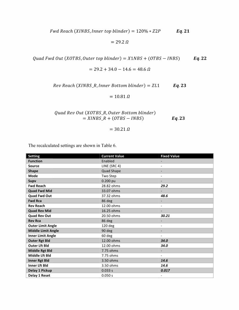
𝐹𝑤𝑑𝑅𝑒𝑎𝑐ℎ 𝑋𝐼𝑁𝐵𝑆, 𝐼𝑛𝑛𝑒𝑟𝑡𝑜𝑝𝑏𝑙𝑖𝑛𝑑𝑒𝑟 = 120% ∗ 𝑍2𝑃𝑬𝒒. 𝟐𝟏
= 29.2𝛺 𝑄𝑢𝑎𝑑𝐹𝑤𝑑𝑂𝑢𝑡 𝑋𝑂𝑇𝐵𝑆, 𝑂𝑢𝑡𝑒𝑟𝑡𝑜𝑝𝑏𝑙𝑖𝑛𝑑𝑒𝑟 = 𝑋1𝑁𝐵𝑆 + (𝑂𝑇𝐵𝑆 − 𝐼𝑁𝐵𝑆)𝑬𝒒. 𝟐𝟐
= 29.2 + 34.0 − 14.6 = 48.6𝛺
𝑅𝑒𝑣𝑅𝑒𝑎𝑐ℎ 𝑋𝐼𝑁𝐵𝑆_𝑅, 𝐼𝑛𝑛𝑒𝑟𝐵𝑜𝑡𝑡𝑜𝑚𝑏𝑙𝑖𝑛𝑑𝑒𝑟 = 𝑍𝐿1𝑬𝒒. 𝟐𝟑
= 10.81𝛺
𝑄𝑢𝑎𝑑𝑅𝑒𝑣𝑂𝑢𝑡 𝑋𝑂𝑇𝐵𝑆_𝑅, 𝑂𝑢𝑡𝑒𝑟𝐵𝑜𝑡𝑡𝑜𝑚𝑏𝑙𝑖𝑛𝑑𝑒𝑟= 𝑋𝐼𝑁𝐵𝑆_𝑅 + 𝑂𝑇𝐵𝑆 − 𝐼𝑁𝐵𝑆 𝑬𝒒. 𝟐𝟑
= 30.21𝛺
The recalculated settings are shown in Table 6. Setting CurrentValue FixedValueFunction Enabled -Source LINE(SRC4) -Shape QuadShape -Mode TwoStep -Supv 0.200pu -FwdReach 28.82ohms 29.2QuadFwdMid 33.07ohms -QuadFwdOut 37.32ohms 48.6FwdRca 86deg -RevReach 12.00ohms -QuadRevMid 16.25ohms -QuadRevOut 20.50ohms 30.21RevRca 86deg -OuterLimitAngle 120deg -MiddleLimitAngle 90deg -InnerLimitAngle 60deg -OuterRgtBld 12.00ohms 34.0OuterLftBld 12.00ohms 34.0MiddleRgtBld 7.75ohms -MiddleLftBld 7.75ohms -InnerRgtBld 3.50ohms 14.6InnerLftBld 3.50ohms 14.6Delay1Pickup 0.033s 0.017Delay1Reset 0.050s -

Delay2Pickup 0.017s -Delay3Pickup 0.009s -Delay4Pickup 0.017s -Seal-InDelay 0.400s -TripMode Delayed -Block OFF -Target Self-reset -Event Enabled -
Table 6. Recalculated Setting Values The corrected inner blinder is out of zone 2. The corrected inner and outer blinders still overlap the load encroachment region but there is no way around this. The new out-of-step is shown in figure 8.
-50 -40 -30 -20 -10 10 20 30 40 50
60
50
40
30
20
10
-10
-20
-30
-40 Figure 8. Plots of Recalculated Setting
Since the load impedance is smaller than that of zone 2, it is impossible to set the outer blinder with the philosophy that the outer line should be smaller than load impedance with margin. For this case, “If the load region encroaches into the distance element and one wants to block under swings, then it is impossible to place the PSB characteristics between the load and distance regions, and one cannot apply the conventional PSB blocking function. A more modern relaying system with ‘load encroachment’ capabilities could be required.” (4) Since there is no guaranteed that the relay will operate correctly for this type of case, we need to rely on other types of algorithms to ensure that the relays will trip for faults at maximum load conditions and when the OOS function is set. Most terminals are designed with complete isolated and redundant systems that include a line current differential and a step distance relay with high speed communications. “At the same time, the differential scheme is unaffected by external effects such as faults, load and power swings”. (3) Even if the OOS function blocks during

loadability limit conditions, the line differential will still trip during faults. In addition, the OOS function can be disabled based on the best engineer judgment.
V. Conclusion As discussed throughout this paper, the employment of load encroachment and OOS blinders make it difficult to ensure that the relay will operate for symmetrical faults when these two functions are enabled and still comply with the standard. The use of current differential relays solves this issue when these type of relays are available. The relay engineer can also decide to disable the OOS function based on the utility engineer best judgment. VI. References [1] System Protection and Control Task Force of the North American Electric Reliability
Council, “Increase Loadability by Enabling Load Encroachment Functions of Digital Relays,” December 2005.
[2] Schweitzer Engineering Laboratories, 421 Instructional Manual. [3] “Guide for Application of Digital 2 Line Current Differential Relays 3 Using Digital
ommunication.” IEEE Power En gineering Society Power System Relay Committee Special Report, New York, NY; 2015.
[4] “Power Swing and Out-of-Step Considerations on transmission” IEEE Power Engineering Society Power System Relay Committee Special Report, New York, NY; 2005.
VII. Author Biographies Seunghwa Lee holds a Bachelor’s of Science degree in Electrical Engineering from Seoul National University, in South Korea. He also received a Masters of Engineering degree in Electrical Engineering from Texas A&M University with concentration in Power Systems. In 2014, Seunghwa became a registered professional engineer in the State of Texas (License No.118682). He is currently working on all projects related to power protection.
Joe Perez received his B.S. degree in Electrical Engineering from Texas A&M University in 2003. Joe is the author of many relay application notes and has presented technical papers at WPRC, Texas A&M and Georgia Tech Relay Conferences. Joe is the owner of SynchroGrid, a registered professional engineer in the state of Texas and a member of PSRC, IEEE, and PES. Joe resides in the Bryan/College Station area. He can be contacted at [email protected].